-
Contents
-
Table of Contents
-
Bookmarks
Quick Links
INTEGRATED MONITORING SYSTEM
Installation Manual
www.opwglobal.com
Part Number:
M1600, Revision — 7
Central Technical Support Number:
1-877-OPW-TECH (877-679-8324)
Issue
Date: 1/15/20
Calls outside US and Canada:
1-708-485-4200
Fax:
1 (800) 421-3297
Supersedes:
1/9/2015
Hours:
Monday through Friday, 7:00 am to 6:00 pm, US CST
Related Manuals for Dover OPW SiteSentinel iSite
Summary of Contents for Dover OPW SiteSentinel iSite
-
Page 1
INTEGRATED MONITORING SYSTEM Installation Manual www.opwglobal.com Part Number: M1600, Revision — 7 Central Technical Support Number: 1-877-OPW-TECH (877-679-8324) Issue Date: 1/15/20 Calls outside US and Canada: 1-708-485-4200 Fax: 1 (800) 421-3297 Supersedes: 1/9/2015 Hours: Monday through Friday, 7:00 am to 6:00 pm, US CST… -
Page 2
Page 2 of 145 2013 Delaware Capital Formation, Inc. All Rights Reserved. DOVER and the DOVER logo are registered trademarks of Delaware Capital Formation, Inc., a wholly owned subsidiary of Dover Corporation. OPW Fuel Management Systems’ System and Replacement Parts Warranty Statement OPW Fuel Management Systems warrants that all OPW Tank Gauge and Petro Vend Fuel Control systems supplied by OPW Fuel Management Systems to the Original Purchaser will be free from defects in material and/or workmanship under normal use and service for a period of 12 months from the date of installation or 18 months from the date of shipment from OPW. -
Page 3: Table Of Contents
Page 3 of 145 Table of Contents Contents Before You Begin ……………………………………..10 Installer Safety ………………………………………. 10 Precision Leak Test ……………………………………..10 Initial Inspection ……………………………………..10 Manifolded Tanks ……………………………………..10 System Overview ……………………………………..11 SiteSentinel® iSite™ Console ………………………………….11 2.1.1 Blank Door Unit ………………………………………
-
Page 4
Page 4 of 145 Probe Placement ……………………………………..29 Probe Installation in Underground Tanks ………………………………. 30 3.2.1 Calculating Product Offset ………………………………….31 Probe Installation ……………………………………..32 Adaptor Collar & Riser Cap …………………………………… 32 Probe Floats ……………………………………….32 Model 924B Probes ……………………………………..35 Flex Probe Installation …………………………………… -
Page 5
Page 5 of 145 5.7.1 Installation ……………………………………… 46 Discriminating STP Sump Sensor …………………………………. 47 5.8.1 Installation ……………………………………… 47 Hydrocarbon Vapor Sensor …………………………………… 48 5.9.1 Installation ……………………………………… 48 5.10 Discriminating Interstitial Sensor ………………………………….49 5.10.1 Installation ……………………………………… 49 5.11 Interstitial Hydrocarbon Liquid Sensor with Water Indicator …………………………… 50 5.12 Hydrocarbon Liquid Sensor with Water Indicator ……………………………. -
Page 6
Page 6 of 145 6.1.2 Installation ……………………………………… 64 Line Interface Module (LIM) ………………………………….. 65 7.1.1 Installation Overview……………………………………66 Conduit & Cabinet Installation ………………………………….68 Console Installation ……………………………………..68 VSmart Module Installation …………………………………… 69 Line Interface Module (LIM) Installation ………………………………… 69 Probe &… -
Page 7
Page 7 of 145 13.1 Prior to Installation ……………………………………..86 13.2 Installation Procedure ……………………………………. 86 13.2.1 ACR/RIM Hardware Installation ………………………………..87 13.2.2 ACR/RIM Board Jumper Setup ………………………………..89 Appendix A: Model 924B Probe Part Numbers ………………………………..91 Appendix B: Output Relay Installation Report ………………………………..92 Appendix C: Sensor Labels …………………………………….. -
Page 8
Page 8 of 145 Interstitial Level Sensors ……………………………………..131 Hydrocarbon Liquid Sump Sensor ………………………………….132 Interstitial Optical Liquid Sensor ……………………………………. 133 Appendix J: Console Boards …………………………………….. 134 Appendix K: System Functional Testing ………………………………….137 Appendix L: Annual Inspection Checklist ………………………………….140 Declaration of Conformity …………………………………….. -
Page 9
Page 9 of 145 Applicable Warnings The inside of the SiteSentinel→ iSite Console contains no useable parts and operates on high-voltage circuitry; therefore, ONLY certified technicians should be allowed to access the console. However, the internal printer (if installed) may be accessed by the user for regular maintenance including paper replacement. -
Page 10: Before You Begin
Page 10 of 145 Most regulatory agencies will accept the ATG tank test as the Before You Begin acceptance test on new tank installations. 1.3 Initial Inspection Improper installation may endanger installers and users of this equipment! Read these instructions CAREFULLY. The console Data Sheet, which can be downloaded from the OPW 1.1 Installer Safety Global website at www.opwglobal.com, provides specific details about…
-
Page 11: System Overview
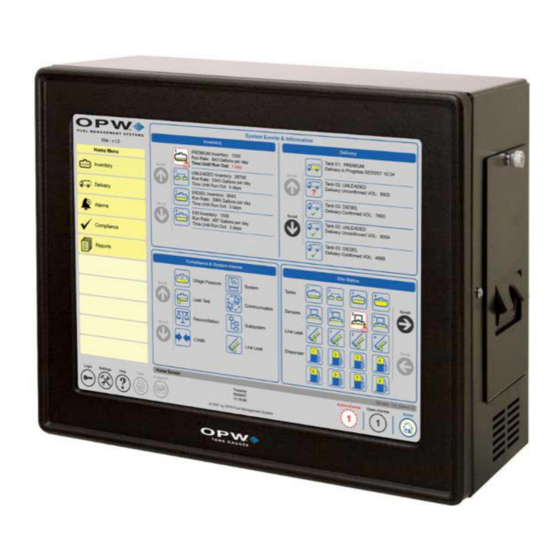
Page 11 of 145 System Overview SiteSentinel® iSite™ Console Specifications 2.1 SiteSentinel® iSite™ Console Width: 15” (38.1 cm) Height: 12” (30.5 cm) Dimensions: The SiteSentinel® iSite™ console (Figure 1-1 SiteSentinel® iSite™ Depth: 7” (17.8 cm) Console) monitors up to 256 probes, 64 AST (Flex) probes, 1,024 sensors or combination of each.
-
Page 12: Network Connections
Page 12 of 145 2.2 Network Connections 2.2.1 DHCP and Static IP Connections When a PC logs onto a network, it obtains an Internet Protocol (IP) address in one of two ways by Dynamic Host Configuration Protocol (DHCP) (Figure 2-1 Dynamic Host Configuration Protocol (DHCP)) or by Static IP (Figure 2-2).
-
Page 13: Direct Connections
Page 13 of 145 2.2.2 Direct Connections To establish a direct, wired connection between the SiteSentinel® iSite™ Console and a PC, a CAT5 crossover cable is required. Follow these steps to connect: 1. Connect one end of the CAT5 crossover cable to the console’s Ethernet port, and the other end to an available Ethernet port on the PC.
-
Page 14: Peripheral Connections
Page 14 of 145 2.3 Peripheral Connections 2.3.2 Wireless Connections Wireless connections can also be used for communications between the 2.3.1 Petro-Net™ Connections VSmart Module and the SiteSentinel® iSite™ console. For this type of Wired RS-485 Petro-Net™ connections can be used for communications connection, a wireless modem is connected to the VSmart Module, and a second modem is wired to the console’s RS-485 port.
-
Page 15
Page 15 of 145 Figure 2-4 Console Connectivity www.opwglobal.com… -
Page 16
Page 16 of 145 Antenna Ethernet Modem Ports USB Ports Serial Ports Port Ports Figure 2-5 Port Connections www.opwglobal.com… -
Page 17
Page 17 of 145 Figure 2-6 Wiring Connections www.opwglobal.com… -
Page 18: The Vsmart Module
Page 18 of 145 Up to eight (8) VSmart Modules can be connected to the SiteSentinel® 2.4 The VSmart Module iSite™ console via Petro-Net™ (twisted pair), Ethernet, or wireless connections for a total of 1,024 devices per system. The VSmart Module is where all monitored devices (probes, sensors, and line-leak detectors) are physically connected to the system through Intrinsically Safe (IS) barriers.
-
Page 19
Page 19 of 145 VSmart Module Specifications Width: 11.3” (28.7 cm) Height: 5.6” (14.2 cm) Dimensions: Depth: 5.8” (14.7 cm) Standard Voltage Supply: 105 to 265 VAC, 50-60 Hz Power Consumption: 60 watts maximum Figure 2-8 VSmart Module (Internal) Temperature Range: -40F to 158F (-40°C to 70°C) For site upgrades from an earlier version of a onsole in which the… -
Page 20: Vsmart Module Connections
Page 20 of 145 2.4.2 VSmart & I/O Module AC Wiring 2.4.1 VSmart Module Connections 1. Pull two AC power wires from the circuit breaker to each You must remove the Intrinsically Safe barrier panel to attach wiring. module; you may “daisy chain” the wires from module to VSmart power must be off while connecting wires! Connect the probe module, not to exceed the circuit-breaker rating (see Figure 2-9).
-
Page 21
Page 21 of 145 Figure 2-10 Petro-Net and A/C Wiring To maintain intrinsic safety, a separate and completely independent ground connection MUST be run from the I.S. GND terminal on each VSmart Module directly back to the main panel. www.opwglobal.com… -
Page 22
Page 22 of 145 Figure 2-11 Standard Twisted-Pair Petro-Net Installation www.opwglobal.com… -
Page 23
Page 23 of 145 Note 2 It is highly recommended that all wireless Petro-Net installations are subjected to a site survey prior to installation to identify potential interference problems. Figure 2-12 Wireless Petro-Net with VSmart in a Building www.opwglobal.com… -
Page 24
Page 24 of 145 Note 2 It is highly recommended that all wireless Petro-Net installations are subjected to a site survey prior to installation to identify potential interference problems. Figure 2-13 Wireless Petro-Net with VSmart Pole-Mounted Outside www.opwglobal.com… -
Page 25
Page 25 of 145 Figure 2-14 Petro-Net Over Ethernet Option www.opwglobal.com… -
Page 26: Tank Alert Modules
Page 26 of 145 2.5 Tank Alert Modules The SiteSentinel® iSite™ console has the ability to trigger an overfill alarm using the Tank Alert module (Figure 2-16). This module has an audible buzzer and an external light to warn the users in an event of overfill or high-product alarm.
-
Page 27
Page 27 of 145 Figure 2-17 Petro-Net Conduit Installation Wireless or Ethernet connections can be substituted during Petro-Net™ installation. www.opwglobal.com… -
Page 28: Internal Printer
Page 28 of 145 2.6 Internal Printer An internal thermal printer option is available for the SiteSentinel® iSite™ Console. The printer will install inside the cabinet. The printer will be used for printing the various reports the SiteSentinel® iSite™ has available.
-
Page 29: Tank Preparation
Page 29 of 145 Tank Preparation 3.1 Probe Placement The ideal location for a probe is in the center of the tank (Figure 3-1). The probe should be located at least 3 feet (91.4 cm) from the tank fill pipe. If this distance is less than 3 feet (91.4 cm), the force of the product entering the tank can cause the water float to rise up the shaft of the probe.
-
Page 30: Probe Installation In Underground Tanks
Page 30 of 145 3.2 Probe Installation in Underground Tanks 1. Refer to Figure 3-2. Install a manhole of at least 18 inches (45.7 cm) diameter around an unused fitting in the top of the tank. This manhole must be large enough to accommodate a weatherproof junction box.
-
Page 31: Calculating Product Offset
Page 31 of 145 3.2.1 Calculating Product Offset You can calculate product offset for a probe that is not installed in the center of a «pitched» tank. Pitch is the tilt of a tank along its horizontal axis. Some tanks are intentionally installed with one end lower than the other to allow water and sediment to collect at the low end, while clear product is drawn from the high end.
-
Page 32: Probe Installation
Page 32 of 145 Probe Installation Probe Floats 4.1 Adaptor Collar & Riser Cap Probe Type/Float Style: Float Kits A modified adaptor collar and riser cap is required for each probe. These Gas: 30-1508-02 collar and riser cap kits are available from OPW Fuel Management 924 and 924B 4”…
-
Page 33
Page 33 of 145 www.opwglobal.com… -
Page 34
Page 34 of 145 Figure 4-1 924B Probe Installation www.opwglobal.com… -
Page 35: Model 924B Probes
Page 35 of 145 4.3 Model 924B Probes Model 924B Probe Specifications The 924B Probe (Figure 4-2) is OPW’s latest probe model. This probe comes standard in stainless steel and can be used in a variety of Power Requirements: Nominal 12+ VDC from VSmart I.S. Module liquids, including gasoline, diesel and water.
-
Page 36
Page 36 of 145 The 7100V Flex Probe (Figure 4-3) utilizes the same magnetostrictive Model 7100V Flex Probe technology for above ground tanks up to 50 feet (15.2 m) in height. It is important to follow the handling instructions to avoid damaging the probe and voiding the warranty. -
Page 37: Flex Probe Installation
Page 37 of 145 4.5 Flex Probe Installation 4.5.2 Installation Preparations Proper operation of the SiteSentinel® iSite™ system using the flex Measure the product level in the tank. Keep tank out of probe depends on the correct sizing of the probe. If the probe is too service to prevent product level from changing.
-
Page 38: Installing Adaptor, Float, Weight On The Probe
Page 38 of 145 4.5.4 Installing Adaptor, Float, Weight on the Probe 4.5.5 Installing the Flex Probe 12. Carry the probe to the top of the tank in its rolled-up state. 19. Position the coiled probe over your shoulder so that the coil 13.
-
Page 39: Finishing The Flex Probe Installation
Page 39 of 145 4.5.6 Finishing the Flex Probe Installation 25. Connect the probe wiring bushing ½-inch NPT to the junction box using a short length [18 inches (45.7 cm) max] of flex conduit. 26. Connect the probe to the cable in the junction box and console as below.
-
Page 40: Flex Probe Specifications
Page 40 of 145 4.5.7 Flex Probe Specifications Dead Zone Multiple RTD Thermistor Location Overall Length Dead Band Clearance Probe Type Overall Probe Length Thermistor Location 51”-144” (130-366 cm) 6” (15.2 cm) 1” (2.5 cm) Shorter than 144” (366 cm) (Temp Span +7”…
-
Page 41: Sensors
Page 41 of 145 Sensors The new smart sensors have the ability to monitor all contained areas of the fuel-storage system: tank interstice, piping sumps, STP containment sumps, dispenser sumps/pans and monitoring wells. Sensors connected to the VSmart Module are automatically detected and identified by the console.
-
Page 42: Interstitial Level Sensor Float Switch
Page 42 of 145 This technology allows the SiteSentinel® iSite™ and VSmart Module to 5.3 Interstitial Level Sensor Float Switch automatically detect sensor connection, sensor type and sensor status, Part No. 30-0231-S will minimize user entry error and identify hardware issues with minimal troubleshooting.
-
Page 43: Single-Level Sump Sensor
Page 43 of 145 Maximum Wiring Length is the maximum length of cable to be used to 5.4 Single-Level Sump Sensor connect all sensors on an individual channel. This length includes run Part No. 30-0231-L of cable from VSmart to each sensor board in the string. The Single-Level Sump Sensor (Figure 5-4) is designed to detect the 5.4.1 Installation presence of liquid in sumps, dispenser pans and other locations where…
-
Page 44: Universal Sump Sensor
Page 44 of 145 5.5 Universal Sump Sensor The Universal Sump Sensor (Figure 5-5) is used in an attached manway riser, double-wall piping, or an attached collar riser. A sump sensor detects the presence of any liquid in a piping sump. When enough liquid enters the sump riser, it activates the sump sensor.
-
Page 45: Liquid-Only Float Sensor
Page 45 of 145 5.6 Liquid-Only Float Sensor *Maximum Wiring Length is the maximum length of cable to be used to connect all sensors on an individual channel. This length includes Part No. 30-0230-S run of cable from VSmart to each sensor board in the string. Designed to detect the presence of fluid in the interstitial space of a steel 5.6.1 Installation double-walled tank or a containment sump.
-
Page 46: Discriminating Dispenser Pan Sensor
Page 46 of 145 5.7 Discriminating Dispenser Pan Sensor *Maximum Wiring Length is the maximum length of cable to be used Part No. 30-0232-DH-10 to connect all sensors on an individual channel. This length includes The Discriminating Dispenser Pan Sensor (Figure 5-7) detects run of cable from VSmart to each sensor board in the string.
-
Page 47: Discriminating Stp Sump Sensor
Page 47 of 145 *Maximum Wiring Length is the maximum length of cable to be used 5.8 Discriminating STP Sump Sensor to connect all sensors on an individual channel. This length includes Part No. 30-0232-DH-20 run of cable from VSmart to each sensor board in the string. The Discriminating STP Sump Sensor (Figure 5-8) detects abnormally 5.8.1 Installation high or low liquid levels and distinguishes liquid type (water or…
-
Page 48: Hydrocarbon Vapor Sensor
Page 48 of 145 5.9 Hydrocarbon Vapor Sensor Depending on saturation factor, the sensor may require up to 30 minutes to return to normal after vapors have dissipated. Part No. 30-0235-V *Maximum Wiring Length is the maximum length of cable to be used The Hydrocarbon Vapor Sensor (Figure 5-9) detects hydrocarbon to connect all sensors on an individual channel.
-
Page 49: Discriminating Interstitial Sensor
Page 49 of 145 *Maximum Wiring Length is the maximum length of cable to be used 5.10 Discriminating Interstitial Sensor to connect all sensors on an individual channel. This length includes Part No. 30-0236-LW run of cable from VSmart to each sensor board in the string. The Discriminating Interstitial Sensor (Figure 5-10) utilizes a solid-state 5.10.1 Installation optical technology to detect the presence of fluid in the annular space of…
-
Page 50: Interstitial Hydrocarbon Liquid Sensor With Water Indicator
Page 50 of 145 *Maximum Wiring Length is the maximum length of cable to be used 5.11 Interstitial Hydrocarbon Liquid Sensor with to connect all sensors on an individual channel. This length includes Water Indicator run of cable from VSmart to each sensor board in the string. Part No.
-
Page 51: Hydrocarbon Liquid Sensor With Water Indicator
Page 51 of 145 5.12 Hydrocarbon Liquid Sensor with Water Hydrocarbon Liquid/Water Sensor Specifications Indicator Part Nos.: 6 feet: 30-0234-HW-06; 15 feet: 30-0234-HW-15; Primary Use(s): Monitoring wells 20 feet: 30-0234-HW-20 Detects: Liquid hydrocarbons and water The Hydrocarbon Liquid/Water Sensor (Figure 5-12), which is available in lengths of 6 feet (1.8 m), 15 feet (4.6 m) and 20 feet (6.1 Operating Temperature: -40°F to 158°F (-40°C to +70°C)
-
Page 52: Interstitial Sensor
Page 52 of 145 5.13 Interstitial Sensor Interstitial Sensors can be installed around the inside perimeter of the retaining wall or “snaked” under the length of an above ground storage tank within the retaining wall area (Figure 5-13 and Figure 5-14). Interstitial Sensors can also be installed in manways (Figure 5-14), in trenches or inside a sump.
-
Page 53: Dual-Float Dispenser Sump Sensor
Page 53 of 145 5.14 Dual-Float Dispenser Sump Sensor Maximum Wiring Length is the maximum length of cable to be used to connect all sensors on an individual channel. This length includes Part No. 30-0232-D-10 run of cable from VSmart to each sensor board in the string. This Dual-Float Sensor is the same as a Discriminating Dispenser Pan ®…
-
Page 54: Dual-Float Stp Sump Sensor
Page 54 of 145 Maximum Wiring Length is the maximum length of cable to be used 5.15 Dual-Float STP Sump Sensor to connect all sensors on an individual channel. This length includes Part No. 30-0232-D-20 run of cable from VSmart to each sensor board in the string. This Dual-Float Sensor is the same as a Discriminating STP Sump ®…
-
Page 55: Dual-Float Brine Sensors
Page 55 of 145 Maximum Wiring Length is the maximum length of cable to be used 5.16 Dual-Float Brine Sensors to connect all sensors on an individual channel. This length includes run of cable from VSmart to each sensor board in the string. 5.16.1 Dual-Float Brine Sensor (D-10) Part No.
-
Page 56: Dual-Float Brine Sensor (D-20B)
Page 56 of 145 Maximum Wiring Length is the maximum length of cable to be used 5.16.2 Dual-Float Brine Sensor (D-20B) to connect all sensors on an individual channel. This length includes run of cable from VSmart to each sensor board in the string. Part No.
-
Page 57: Reservoir Sensor Installation
Page 57 of 145 5.17 Reservoir Sensor Installation Use a Universal Reservoir Sensor with hydrostatically monitored tanks. The Reservoir Sensor monitors the level of the liquid in the reservoir of a double-walled tank (Figure 5-19). The sensor has a single float that detects abnormally high or low liquid levels within the reservoir.
-
Page 58: Density Measurement Sensor (Dms)
Page 58 of 145 5.18 Density Measurement Sensor (DMS) Part No. 30-3232 The Density Measurement Sensor (DMS) (Figure 5-20) installs on the pre-existing probe and continuously measures the average density of the fuel in the tank. This provides a measure of even the smallest change in product density within the API density range.
-
Page 59: Dms Installation
Page 59 of 145 “Density Probe” option to be flagged in the Section of “Integrated 5.18.1 DMS Installation Density Sensor,” which is shown below. For density probes, three As density sensing is no longer an option in the system, the sensor density sensors are allowed.
-
Page 60
Page 60 of 145 12. To check current density readings from the system, click “Verify Density Device.” The system will start calculating the density readings and then display the information in the window for verification, as shown below: Figure 5-21 Current Density Values www.opwglobal.com… -
Page 61
Page 61 of 145 Figure 5-22 In-Tank Probe Setup www.opwglobal.com… -
Page 62: Tank Thresholds
Page 62 of 145 3. Click “Verify Density Device Values,” take the difference of 5.18.3 Tank Thresholds the density results from steps 19 and 20 (Density from step 19 minus the density from step 20). 1. As the Density Sensor is installed between the water and 4.
-
Page 63: Leak Detection
Page 63 of 145 *Maximum Wiring Length is the maximum length of cable to be used Leak Detection to connect all sensors on an individual channel. The length includes run of cable from VSmart to each sensor board in the string. 6.1 Volumetric Line Leak Detector (VLLD) Sensor Part No.
-
Page 64: Installation
Page 64 of 145 6.1.2 Installation Remove all pressure from the product piping. 2. Remove the current mechanical leak detector. CAUTION: Be sure to prevent any debris or scaling from entering system through the leak detector opening. 3. Use the fuel-absorbent cloths to soak up fuel within the work area and around the dry pipe threads.
-
Page 65: Line Interface Module (Lim)
Page 65 of 145 Line Interface Module (LIM) The LIM device is a magnetic contactor that supplies line/tank activity Line Leak Interface Module by monitoring input/output status of nozzle signals and Submersible Turbine Pump (STP) contactors. Monitors: Nozzle Signal and STP Contactors Each Line Interface Module (LIM) interface (maximum of four (4) per system) will monitor up to four (4) pressurized lines (for a total of 16 6”…
-
Page 66: Installation Overview
Page 66 of 145 7.1.1 Installation Overview Installation vary depending your submersible pump manufacturer; therefore, installation overview may vary from site to site. Figure 7-2 LIM System Overview Typical FE Petro Connection Figure 7-2 Variable Speed Control Wiring for FE Petro Figure 7-4 Typical FE Petro Wiring Connections www.opwglobal.com…
-
Page 67
Page 67 of 145 Typical Red Jacket Connection Figure 7-6 Typical Red Jacket Wiring Connections Figure 7-5 Variable Speed Control Wiring for Red Jacket www.opwglobal.com… -
Page 68: Conduit & Cabinet Installation
Page 68 of 145 Conduit & Cabinet Installation 8.1 Console Installation Mount the SiteSentinel® iSite™ console on a wall in a secure indoor location using the mounting holes provided, or use the rubber feet included and place on any flat surface for easy access. If possible, align the console so the display is easily visible and at a comfortable eye level (approximately 5 to 6 feet (1.5 to 1.9 m) above ground if mounted on a wall).
-
Page 69: Vsmart Module Installation
Page 69 of 145 8.3 Line Interface Module (LIM) Installation 8.2 VSmart Module Installation The Line Interface Module must be mounted on a wall using ONLY the The VSmart Modules must be mounted on a wall using ONLY the mounting tabs provided. Knockout locations are shown below. LIMs mounting tabs provided.
-
Page 70: Probe & Sensor Conduits
Page 70 of 145 8.4.2 RS-232 Communications Conduits 8.4 Probe & Sensor Conduits If a terminal or PC located more than 6 feet (1.8 m) from the console is All installations must be carried out in accordance with local regulations. to be connected, conduit must be installed to accommodate the RS- Rigid steel conduit, which may or may not be required, should be used 232 cable.
-
Page 71: I/O Device Conduits
Page 71 of 145 To prevent interference, all wiring to and from the VSmart Module must 8.5 I/O Device Conduits be protected by rigid steel conduit. Probe and sensor wires must be Rigid steel conduit should be used for wiring runs to all I/O devices, alone in their conduits.
-
Page 72: Sensor Installation
Page 72 of 145 Due to the variety of surface and soil conditions, a person familiar with Sensor Installation local conditions and codes should determine the placement of monitoring wells. For best results, a groundwater survey should also 9.1 Introduction be completed.
-
Page 73: Dry-Well Monitoring, Single-Wall Tank
Page 73 of 145 9.2 Dry-Well Monitoring, Single-Wall Tank Error! Reference source not found. represents a typical dry-well monitoring layout for a single-wall tank. Monitoring wells are placed around the perimeter of the tanks, and are dug as close as possible to the tanks or product lines for optimal sensor response.
-
Page 74
Page 74 of 145 Figure 9-3 Dry-Well Monitoring, Single-Wall Tank www.opwglobal.com… -
Page 75: Wet-Well Monitoring, Single-Wall Tank
Page 75 of 145 9.3 Wet-Well Monitoring, Single-Wall Tank Error! Reference source not found. shows a typical wet-monitoring ell layout for a single-wall tank. The sensors are placed around the perimeter of the tanks. The monitoring wells are dug as close as possible to the tanks or product lines for optimal sensor response.
-
Page 76: Well Monitoring, Double-Wall Tank
Page 76 of 145 9.4 No-Well Monitoring, Double-Wall Tank The space between the walls of a double-wall tank is the interstitial space, and it is an ideal location for liquid sensors. If the outside tank wall develops a leak, groundwater enters the interstitial space liquid…
-
Page 77: Double-Wall Tank With Well Monitoring
Page 77 of 145 9.5 Double-Wall Tank with Well Monitoring A monitoring well is used with a double-wall tank only if the local water table reaches tank level. Because of the danger of water-table contamination, install the well with a Liquid Phase Sensor. Error! Reference source not found.
-
Page 78
Page 78 of 145 Figure 9-7 Double-Wall Tank with Well Monitoring www.opwglobal.com… -
Page 79: Probe-Cable Seal-Offs
Page 79 of 145 10 Probe-Cable Seal-Offs Seal-off probe cables before they enter the VSmart Module! This prevents explosive vapors from entering the module. Remove enough of the jacket to allow approximately 3 inches (7.6 cm) of wire leads to extend past each seal-off.
-
Page 80: Other System Parameters
Page 80 of 145 Follow these steps to set the Petro-Net™ Address: 11 Other System Parameters Turn the module power OFF. 11.1 VSmart Module Petro-Net™ Addressing 2. Use a ¼-inch (6 mm) blade screwdriver to gently rotate the small white screw inside the rotary switch to the VSmart Modules and I/O Modules must each be assigned a unique desired location.
-
Page 81: Installation With Existing Opw/Eeco Equipment
Page 81 of 145 Five temperature sensors reside in the probe shaft for measuring 12 Installation with Existing OPW/EECO product temperature at different levels in the tank. They are located at positions of approximately 20%, 40%, 60% and 80% of the tank’s Equipment volume.
-
Page 82: Model Eeco Probes
Page 82 of 145 Five temperature sensors reside in the probe shaft for measuring 12.2 Model EECO Probes product temperature at different levels in the tank. They are located at positions of approximately 20%, 40%, 60% and 80% of the tank’s CANNOT BE MULTI-DROPPED ON VSmart.
-
Page 83: Sitesentinel® Isite™ Smart Module
Page 83 of 145 12.3 SiteSentinel® iSite™ Smart Module Smart Module Specifications The Smart Module gathers probe and sensor data. Up to four devices Electrical Requirements can be connected to the Intrinsically Safe (I.S.) barrier in the Smart Standard Voltage Supply: 105 to 125 VAC, 60 Hz Module.
-
Page 84: Waterproof Field Electrical Connections
Page 84 of 145 12.4 Waterproof Field Electrical Connections It is VERY important to seal all probe and sensor connections in the junction box to prevent corrosion of the wires. Twist bare ends of wires together. Secure the connection with a wire nut. DO NOT use electrical tape on any connections! Tape prevents proper sealing of the epoxy.
-
Page 85: Acr/Rim
Page 85 of 145 13 ACR/RIM The ACR/RIM collects pump transaction data from electronic pumps to provide the OPW tank gauges required data for auto-recalibration and reconcile transactions against tank inventories. • ACR — Automatic Calibration and Reconciliation • RIM — Reconciliation Interface Module Due to the flexibility of the system and the unique nature of every site, it is not possible to show every possible installation scenario.
-
Page 86: Prior To Installation
Page 86 of 145 13.2 Installation Procedure 13.1 Prior to Installation All dispensers and controller are installed according to manufacturer’s Check the following: specifications and should be tested for proper operation. 1. Enclosure Mounting: OPW Tank Gauge is installed to specifications Knockouts and mounting means are provided for all cabinetry.
-
Page 87: Acr/Rim Hardware Installation
Page 87 of 145 3. Mount the ACR/RIM board on the left-side stand-offs in the 13.2.1 ACR/RIM Hardware Installation enclosure. Installing ACR/RIM Interface: Attach the enclosure to a wall with fasteners (not-supplied) within 5 feet (1.5 m) of the SiteSentinel® iSite™ controller. Enclosure needs to be in a non-hazardous location.
-
Page 88
Page 88 of 145 5. Locate Wayne Distribution box and wire from CN9 connector to an unused pump position in the D-Box. • Set Jumpers on RIM interface for Wayne • Locate Wayne/Dresser distribution box and wire the other end into an unused pump position in the D-Box. In the event that the D-Box board is full, wire in “series”… -
Page 89: Acr/Rim Board Jumper Setup
Page 89 of 145 13.2.2 ACR/RIM Board Jumper Setup Jumper # Pins Function Pump Type Setup jumpers to match pump type being connected. When a jumper is set as ON, this means the jumper will tie both pins Gilbarco Wayne together.
-
Page 90
Page 90 of 145 Figure 13-7 ACR/RIM Jumper Board www.opwglobal.com… -
Page 91: Appendix A: Model 924B Probe Part Numbers
Page 91 of 145 Appendix A: Model 924B Probe Part Numbers Model 924B Probe Part Numbers Probe Length Length (cm) Part Number 53” Probe for 4’ (122 cm) Diameter/Height Tank 134.6 cm 30-B053 69” Probe for 5’ (152 cm) Diameter/Height Double-Wall Tank 175.3 cm 30-B069 77”…
-
Page 92: Appendix B: Output Relay Installation Report
Page 92 of 145 Appendix B: Output Relay Installation Report Output Relay Installation Records Output Location: Output Controls: Normally Open/Normally Closed I/O Module Number (Internal/External OM4) (External Alarm, Dispenser etc.) SiteSentinel® iSite™ Internal Relay Output 1 SiteSentinel® iSite™ Internal Relay Output 2 External Output 1 Position 1 External Output 1 Position 2 External Output 1 Position 3…
-
Page 93
Page 93 of 145 Appendix B (cont.) Output Relay Installation Records Output Location Output Controls: Normally Open/Normally Closed I/O Module Number (Internal/External OM4) (External Alarm, Dispenser etc.) External Output 3 Position 3 External Output 3 Position 4 External Output 4 Position 1 External Output 4 Position 2 External Output 4 Position 3 External Output 4 Position 4… -
Page 94: Appendix C: Sensor Labels
Page 94 of 145 Appendix C: Sensor Labels Installed Sensor Labels Description (Location, e.g. Sump, Sensor #) Place Label Here Place Label Here www.opwglobal.com…
-
Page 95
Page 95 of 145 Appendix C (continued) Installed Sensor Labels Description (Location, e.g. Sump, Sensor #) Place Label Here Place Label Here www.opwglobal.com… -
Page 96: Appendix D: 7100V Flex Probe Installation Records
Page 96 of 145 Appendix D: 7100V Flex Probe Installation Records 7100V Flex Probe Installation Records Probe Serial Number Probe Part Number (Catalog #) Tank # Product in Tank VSmart Module Number 1–8 Barrier Position 0–3 www.opwglobal.com…
-
Page 97
Page 97 of 145 Appendix D (continued) 7100V Flex Probe Installation Records Probe Serial Number Probe Part Number (Catalog #) Tank # Product in Tank VSmart Module Number 1–8 Barrier Position 0–3 www.opwglobal.com… -
Page 98: Appendix E: Model 924B Probe Installation Records
Page 98 of 145 Appendix E: Model 924B Probe Installation Records Model 924 Probe Installation Records Probe Serial Number Tank Number Product in Tank VSmart Module Number (1-8) Barrier Position (1-4) (Number in chain, if applicable, 1-4) www.opwglobal.com…
-
Page 99
Page 99 of 145 Appendix E (continued) Model 924 Probe Installation Records Probe Serial Number Tank Number Product in Tank VSmart Module Number (1-8) Barrier Position (1-4) (Number in chain, if applicable, 1-4) www.opwglobal.com… -
Page 100: Appendix F: Icon Glossary
Page 100 of 145 Appendix F: Icon Glossary Sensor Alarms in the Alarm Calendar Alarm Ended But Alarm Condition Description Normal Alarm Acknowledged Unavailable Ended Acknowledged Part numbers and description that would be Icon only seen during Icon outlined with Icon outlined in Icon outlined in Icon completely…
-
Page 101
Page 101 of 145 Appendix F – Icon Glossary (cont.) Sensor Alarms in the Alarm Calendar Alarm Ended But Alarm Condition Description Normal Alarm Acknowledged Unavailable Not Acknowledged Ended Icon outlined in blue Icon completely Icon outlined with a Icon outlined in blue and triangle is blue. -
Page 102
Page 102 of 145 Appendix F- Icon Glossary (cont.) Sensor Alarms in the Alarm Calendar Alarm Ended But Alarm Condition Description Normal Alarm Acknowledged Unavailable Not Acknowledged Ended Icon outlined in blue Icon completely gray. Displayed when Icon outlined with a Icon outlined in blue Icon only seen and triangle is blue. -
Page 103
Page 103 of 145 Appendix F- Icon Glossary (cont.) Sensor Alarms in the Alarm Calendar Alarm Ended But Alarm Condition Description Normal Alarm Acknowledged Unavailable Not Acknowledged Ended Icon only seen during Icon outlined with a Icon outlined in blue Icon outlined in blue Icon completely gray. -
Page 104
Page 104 of 145 Appendix F- Icon Glossary (cont.) Sensor Alarms in the Alarm Calendar Alarm Ended But Alarm Condition Description Normal Alarm Acknowledged Unavailable Not Acknowledged Ended Icon outlined in blue Icon completely Icon outlined with a Icon outlined in blue and triangle is blue. -
Page 105
Page 105 of 145 Appendix F — Icon Glossary (cont.) Sensor Alarms in the Alarm Calendar Alarm Ended But Alarm Condition Description Normal Alarm Acknowledged Unavailable Not Acknowledged Ended Icon outlined in blue Icon completely gray. Icon outlined with a Icon outlined in blue Icon only seen during and triangle is blue. -
Page 106
Page 106 of 145 Appendix F- Icon Glossary (cont.) Sensor Alarms in the Alarm Calendar Alarm Ended But Alarm Condition Description Normal Alarm Acknowledged Unavailable Not Acknowledged Ended Icon outlined in blue Icon completely gray. Icon outlined with a Icon outlined in blue Icon only seen during and triangle is blue. -
Page 107
Page 107 of 145 Appendix F- Icon Glossary (cont.) Sensor Alarms in the Alarm Calendar Alarm Ended But Alarm Condition Description Normal Alarm Acknowledged Unavailable Not Acknowledged Ended Icon outlined in blue Icon completely gray. Icon outlined with a Icon outlined in blue Icon only seen during and triangle is blue. -
Page 108
Page 108 of 145 Appendix F- Icon Glossary (cont.) Probe/Tank Alarms Alarm Ended But Alarm Condition Description Normal Alarm Acknowledged Unavailable Not Acknowledged Ended Icon outlined in blue Icon completely gray. Icon outlined with a Icon outlined in blue Icon only seen during and triangle is blue. -
Page 109
Page 109 of 145 Appendix F- Icon Glossary (cont.) Probe/Tank Alarms Alarm Ended But Alarm Condition Description Normal Alarm Acknowledged Unavailable Ended Not Acknowledged Icon outlined in blue Icon completely Icon outlined with a Icon outlined in blue Icon only seen and triangle is blue. -
Page 110
Page 110 of 145 Appendix F- Icon Glossary (cont.) Probe/Tank Alarms Alarm Ended But Alarm Condition Description Normal Alarm Acknowledged Unavailable Not Acknowledged Ended Icon outlined in blue Icon completely Icon outlined with a Icon outlined in blue Icon only seen and triangle is blue. -
Page 111
Page 111 of 145 Appendix F- Icon Glossary (cont.) Probe/Tank Alarms Alarm Ended But Alarm Condition Description Normal Alarm Acknowledged Unavailable Ended Not Acknowledged Icon outlined in blue Icon completely gray. Icon outlined with a Icon outlined in blue Icon only seen during and triangle is blue. -
Page 112
Page 112 of 145 Appendix F- Icon Glossary (cont.) Probe/Tank Alarms Alarm Ended But Alarm Condition Description Normal Alarm Acknowledged Unavailable Not Acknowledged Ended Icon outlined in blue Icon completely gray. Icon outlined with a Icon outlined in blue Icon only seen during and triangle is blue. -
Page 113
Page 113 of 145 Appendix F- Icon Glossary (cont.) System Alarms Alarm Ended But Alarm Condition Description Normal Alarm Acknowledged Unavailable Not Acknowledged Ended Icon outlined in blue Icon completely gray. Icon outlined with a Icon outlined in blue Icon only seen during and triangle is blue. -
Page 114
Page 114 of 145 Appendix F- Icon Glossary (cont.) System Alarms Alarm Ended But Alarm Condition Description Normal Alarm Acknowledged Unavailable Not Acknowledged Ended Icon outlined in blue Icon completely gray. Icon outlined with a Icon outlined in blue Icon only seen during and triangle is blue. -
Page 115
Page 115 of 145 Appendix F- Icon Glossary (cont.) Communication Ports Port Available Unavailable Icon Available Unavailable Displayed when the port is Displayed when the item is Displayed when the port is Displayed when the item is available for selection. Icon currently unavailable. -
Page 116
Page 116 of 145 Appendix F- Icon Glossary (cont.) Miscellaneous Icons Icon Available Unavailable Icon Available Unavailable Displayed when the port is Displayed when the item is Displayed when the port is Displayed when the item is available for selection. Icon currently unavailable. -
Page 117
Page 117 of 145 Appendix F- Icon Glossary (cont.) Miscellaneous Icons Icon Available Unavailable Icon Available Unavailable Displayed when the port is Displayed when the item is Displayed when the port is Displayed when the item is available for selection. Icon currently unavailable. -
Page 118
Page 118 of 145 Appendix F- Icon Glossary (cont.) Miscellaneous Icons Alarm Ended But Not Description Normal Alarm Acknowledged Alarm Condition Ended Acknowledged Device icon in normal state. Part numbers and Icon outlined with a dotted Icon outlined in blue with red Icon outlined in blue and Icon completely gray. -
Page 119
Page 119 of 145 Appendix F- Icon Glossary (cont.) Miscellaneous Icons Alarm Ended But Not Description Normal Alarm Acknowledged Alarm Condition Ended Acknowledged Part numbers and Icon only seen during auto- Icon outlined with a dotted Icon outlined in blue with red Icon outlined in blue and Icon completely gray. -
Page 120: Appendix G: Maintenance Functions
Page 120 of 145 The USB key contains a file (from the factory) that will be used to Appendix G: Maintenance Functions access the Windows®-side of the console, view log files or transfer files to and from the console. This key will temporarily shut down the Use of Maintenance Kit user interface (not causing anything to stop running).
-
Page 121: Backup And Restore Of Configuration & Backup Database
Page 121 of 145 Restore Configuration Backup and Restore of Configuration & Backup Database Through the user interface, users have the ability to backup the configuration and the database. To do this, log into the Console and go to Settings>Utilities. On this screen, you will see the options Backup Configuration and Restore Configuration.
-
Page 122: Connecting Directly Via Crossover Cable
Page 122 of 145 Once the IP address is found and recorded, enter this IP address into Connecting Directly via Crossover Cable the address bar on Internet Explorer and press Enter to access the To connect to the console directly using a crossover cable, connect a page.
-
Page 123: Appendix H: Om4 Output Module For Sitesentinel Isite
Page 123 of 145 OM4 Output Module Appendix H: OM4 Output Module for ® SiteSentinel iSite Part # 20-8312-iSite The OM4 Output Module (see image on right) expands your SiteSentinel® iSite capabilities by allowing you to connect as many as 16-relay activated output devices to the SiteSentinel®…
-
Page 124: Codes
Page 124 of 145 When installing two or more OM4 Output Module boxes, place the Codes address jumpers on the OM4 circuit boards as shown below. To do this, take off the four nuts securing the aluminum cover and remove it, Relay wiring is classified Class 1 wiring.
-
Page 125: Appendix I: Sitesentinel And Emco Sensors Without Intellisense™ Board
Page 125 of 145 ® Appendix I: SiteSentinel and EMCO Sensors Hydrocarbon Liquid/Water Sensor without IntelliSense™ Board Typical Uses: Monitoring Wells Hydrocarbon Liquid/Water Sensor Part # 30-3210-nn Substances Detected: Hydrocarbon and Water The hydrocarbon liquid/water sensor is used primarily in monitoring wells with fluctuating groundwater tables, or in the containment areas 6’–20’…
-
Page 126: Hydrocarbon Vapor Sensor
Page 126 of 145 Hydrocarbon Vapor Sensor Hydrocarbon Vapor Sensor Part No. 30-3222 Operating Temperature: -40°F to 158° F (-40°C to 70°C) The Hydrocarbon Vapor Sensor is designed to detect hydrocarbon vapors in dry monitoring wells. The presence of these vapors could indicate a potentially dangerous leak that could lead to safety and D= 0.9“…
-
Page 127: Combo Single Level / Hydrocarbon Liquid Sump Sensor
Page 127 of 145 Combo Single Level/Hydrocarbon Liquid Sump Sensor Combo Single Level / Hydrocarbon Liquid Sump Sensor Substances Detected: Liquid Hydrocarbon and Water Part #30-3224 Operating Temperature: -4°F to 122°F (-20°C to +50°C) This sensor is made from the Hydrocarbon Liquid Sump Sensor (30- 3219-12) with an Interstitial Level Sensor (30-3221-1A) clipped to its Dimensions: side.
-
Page 128: Combo Dual Level/ Hydrocarbon Liquid Sump Sensor
Page 128 of 145 Combo Dual Level/ Hydrocarbon Liquid Sump Combo Dual Level/Hydrocarbon Liquid Sump Sensor Sensor Part #30-3225 Substances Detected: Liquid Hydrocarbon and Water This sensor is made from the Hydrocarbon Liquid Sump Sensor (30- 3219-12) with a Dual-Level Reservoir Sensor (30-3221-2) clipped to its side.
-
Page 129: Single Level Sump Sensor
Page 129 of 145 Single Level Sump Sensor Single Level Sump Sensor Part #30-3221-1 The Single Level Sump Sensor is designed to detect the presence of Substance Detected: Liquid liquid in sumps, dispenser pans and other locations where the presence of a liquid could indicate that a leak has occurred. Operating Temperature: -4°F to 122°F (-20°C to +50°C) This sensor can also be used to monitor wet wells to ensure that a…
-
Page 130: Dual Level Reservoir Sensor
Page 130 of 145 Dual Level Reservoir Sensor *Maximum Wiring Length is the maximum length of cable to be used Part # 30-3221-2 to connect all sensors on an individual channel. The length includes The Dual Level Reservoir Sensor is designed for use in the brine-filled run of cable from VSmart to each sensor board in the string.
-
Page 131: Interstitial Level Sensors
Page 131 of 145 Interstitial Level Sensors Interstitial Level Sensor Part #30-3221-1A, 30-3221-1B The Interstitial Level Sensors are used primarily in the interstitial area Substance Detected: Liquid of a double-walled tank. The sensor contains a float switch that activates in the presence of a liquid. The Interstitial Level Sensor is Operating Temperature: -4°F to 122°F (-20°C to +50°C) available in two configurations.
-
Page 132: Hydrocarbon Liquid Sump Sensor
Page 132 of 145 Hydrocarbon Liquid Sump Sensor Hydrocarbon Liquid Sump Sensor Part #30-3219-12 Substance Detected: Liquid Hydrocarbon The Hydrocarbon Liquid Sump Sensor is designed to detect the presence of liquid hydrocarbons in sumps, dispenser pans and other locations where the presence of a hydrocarbon liquid could indicate Operating Temperature: -4°F to 122°F (-20°C to +50°C) that a leak has occurred.
-
Page 133: Interstitial Optical Liquid Sensor
Page 133 of 145 Interstitial Optical Liquid Sensor Interstitial Optical Liquid Sensor Part #30-3223 The Interstitial Optical Liquid Sensor is used primarily to monitor the Substance Detected: Liquid interstitial area of double-walled tanks. This sensor incorporates a long-life optical prism and can also be used in sumps, dispenser pans Operating Temperature: -4°F to 122°F (-20°C to +50°C) and other locations where the presence of a liquid could indicate that a…
-
Page 134: Appendix J: Console Boards
Page 134 of 145 Appendix J: Console Boards NOTE: For COM 5 (RS-485 Petro-Net Port • Position 3 − Position 2 on VSmart • Position 4 − Position 1 on VSmart Flash Card Socket Ethernet Port (x2) COM 10 (Internal Modem Port) Serial Printer COM 11 (Internal Modem Port) COM 12 (Internal Modem Port)
-
Page 135
Page 135 of 145 All CLOSED Petro-Net (ON) for Address 1-8 (only Normal 0 and 9 used for Reset Barrier #1 Barrier #2 Operation factory test) Button Channels 1-4 Channels 5-8 1 – Top Status LED 2 – ON when collecting data from flex probe or other analog device 3 –… -
Page 136
Page 136 of 145 Disc Ethernet Activity Activity External Reset External LEDs PS2 Port Button VGA Port Port www.opwglobal.com… -
Page 137: Appendix K: System Functional Testing
Page 137 of 145 Appendix K: System Functional Testing 1) Tank-Level Monitor Functions a) Confirm Probe reading correct product level: b) Print inventory report, measure product level at or near Probe riser and confirm probes reading correctly: 2) Leak-Sensor Functions a) Sensor Function Tests: b) Sensor Model(s) 30-0231-S, 30-0230-S, 30-0232-D-10 &30-0232-D-20 &30-0232-D-10B, 30-0232-D-20B: c) Individually remove sensor from mounting bracket/riser, then place sensor upside down (on sensor models 20 -0232-D-XX- remove sensor…
-
Page 138
Page 138 of 145 monitoring the site. Must be last function performed for checklist verification! All event History printed and reviewed for proper operation and verification: 5) Attach all required printouts and reports. 6) Document all “No” answers, actions taken to correct those items, and/or comments. www.opwglobal.com… -
Page 139
Page 139 of 145 7) Include site drawing with layout and approximate distances (use space provided below): This checklist is for annual verification of the OPW Fuel Management Systems’ SiteSentinel® iSite™ Tank Gauge System and must be performed by an OPW Fuel Management Systems’ Authorized Service Contractor. The compilation of this checklist and any subsequent work or parts required to address any non-conformity is the sole responsibility of the equipment owner. -
Page 140: Appendix L: Annual Inspection Checklist
Page 140 of 145 Appendix L: Annual Inspection Checklist Facility ID#: Facility Name/Address: Qualified Technician Signature: Date: If any problem is found, Contact contact: information: Console Description Tank 1 Tank 2 Tank 3 Tank 4 Tank 5 Alarm is functional External Alarm Alarm sounds at the proper product level Leak Detection…
-
Page 141
Page 141 of 145 Soil Vapor Sensing device calibrated and tested Monitoring Groundwater Sensing device tested Monitoring Verify that no line sensors have been disabled and electrically by-passed Electronic Line- Leak Detection Evaluate the leak-test history for information indicating that the system is successfully performing the desired tests Evaluate the alarm history for a pattern of leak-test failures or system problems… -
Page 142: Declaration Of Conformity
Page 142 of 145 Declaration of Conformity www.opwglobal.com…
-
Page 143
Page 143 of 145 www.opwglobal.com… -
Page 144: Index
Page 144 of 145 Index ACR ……………….. 84, 85, 86, 87, 88 Hazardous Areas ………………..84 Adapter Collar & Riser Cap …………….32 Hydrocarbon Liquid with Water Indicator …………50 Alpha 55371 ………………..19, 34, 45 Hydrocarbon Vapor Sensor……………. 47, 125 Applicable Warnings …………………
-
Page 145
Page 145 of 145 Petro-Net ………………14, 19, 69, 70, 82 Single-Wall Tank—Dry Well Monitoring …………72 Precision Leak Test ……………….. 10 Single-Wall Tank—Wet Well Monitoring …………74 Printer ………………..11, 28, 118 SITE SURVEY ………………..14 Probe & Sensor Conduit ………………69 Smart Module………………19, 20, 82, 100 Probe &… -
Page 146: Notes
Page 146 of 145 NOTES: www.opwglobal.com…
Количество загрузок:241 (1 за последнюю неделю)
Операционная система:Windows XP/7/8/10/11
Последняя версия:8.7.0.22
Сообщить о неточности
Описание

Cкриншот
Версия 8.7.0.22 SiteConnect предоставлена бесплатно на нашем архиве. Эта бесплатная программа устанавливается на Windows XP/7/8/10/11, 32-бит версию.
Файл последней версии установочного пакета 18.3 MB. Эта бесплатная программа была разработана OPW Fuel Managment Systems.
SiteConnect принадлежит к категории Системные утилиты, а точнее к подкатегории Помощники устройств.
Наиболее часто используемое название файла установки программы: SSIConnect.exe. Наш встроенный антивирус просканировал эту загрузку и признал ее как 100% безопасную. Версии 8.7, 8.6 и 8.2 наиболее популярны среди пользователей.
От разработчика:
SiteConnect is a PC software used to configure your SiteSentinel iTouch / SiteSentinel1 Automatic Tank Gauge. You can configure various parameters, such as the product reference table, IS module setup, site configuration,alarm setup, iTouch port parameters, TCP IP and e-mail configuration, the controller LCD display volume and density, and more.
Мы предлагаем оценить другие программы, такие как Epson Connect Printer Setup или Atomic Email Hunter, которые часто используются вместе с SiteConnect.
Назначение
Системы измерений уровня и контроля утечек SiteSentinel (далее — система SiteSentinel или система) предназначены для непрерывных измерений уровня, температуры и плотности нефтепродуктов, уровня и температуры подтоварной воды в резервуарах автозаправочных станций (далее — АЗС) и нефтебаз, вычислений объёма и массы нефтепродуктов при хранении, отпущенных и полученных в резервуары АЗС и нефтебаз, а также для индикации утечек нефтепродуктов из резервуаров.
Описание
В системах реализован косвенный метод статических измерений массы светлых нефтепродуктов по ГОСТ Р 8.595-2004. В соответствии с ГОСТ Р 8.596-2002 системы относятся к типу ИС-2.
Системы состоят из каналов измерений количества нефтепродуктов, число которых равно числу резервуаров на объекте (АЗС или нефтебаза), а также блоков индикации утечек нефтепродуктов.
Каждый из каналов измерений количества нефтепродуктов состоит из следующих функциональных элементов (рисунок 1):
— магнитострикционный зонд уровнемера (модели 924Х и 7100, далее — зонд) с закрепленными на стержне зонда измерительными преобразователями температуры пятиточечными YSI 44006 и электронным преобразователем измеренных сигналов в цифровые значения уровня и температуры;
— контроллер (модели SiteSentinel iTouch , SiteSentinel iSite или SiteSentinel Integra, показаны на рисунках 3.1 — 3.3);
— устройство для определения плотности нефтепродукта (далее — плотномер, показан на рисунке 4); плотномером комплектуются только зонды модели 924Х;
— блок сопряжения модели VSmart Module (рисунок 5) выполняет и функции блока искрозащиты.
В зависимости от типа резервуара зонды выпускаются в двух модификациях:
— 924Х — для установки в горизонтальные цилиндрические резервуары и резервуары других типов с базовой высотой до 6,0 м (рисунок 2.1);
— 7100 — для установки в вертикальные резервуары с базовой высотой до 20,0 м, рисунок 2.2.
В верхней части зонда имеется магнитострикционный преобразователь с излучателем и приемником; вниз отходит стержень из нержавеющей стали с расположенными на нем двумя поплавками (верхний — для измерений уровня нефтепродуктов, нижний — для измерений уровня подтоварной воды); внутри стержня проходит магнитопровод, состоящий из алюминиево-магниевого стержня специального профиля и струны из никелевого сплава. Зонд 7100 имеет гибкое исполнение.
В поплавках находятся кольцевые магниты. Волна, пришедшая от магнитострикци-онного преобразователя-излучателя, взаимодействует с полем магнитов и возбуждает в струне акустический сигнал, распространяющийся по струне вверх и вниз. Сигнал, пришедший в головку зонда, регистрируется и обрабатывается в магнитострикционном преобразователе-приёмнике (при этом значение сигнала пропорционально уровню жидкости) и передается в контроллер по интерфейсу. Контроллер подключается к компьютеру по интерфейсу RS232.
Имеется 3 вида поплавков для разных групп нефтепродуктов (бензины, дизельное топливо и СУГ).
Измерительные преобразователи температуры (термисторы), закреплённые равномерно в пяти точках по длине стержня зонда вырабатывают сигналы, соответствующие температуре жидкости. В электронном преобразователе зонда формируются сигналы в цифровом формате, соответствующие значениям уровней и температуры, а также плотности нефтепродукта при использовании зонда с плотномером.
Плотномер состоит из корпуса и поплавка, соединённых пружиной. Корпус закрепляется неподвижно на стержне зонда, поплавок — на пружине и может перемещаться. При этом его перемещение зависит от плотности нефтепродукта. Плотномер устанавливается на стержне зонда в зоне нижнего уровня нефтепродукта над поплавком для измерения уровня подтоварной воды.
Если зонд, установленный в резервуаре, не имеет плотномера, то плотность нефтепродукта определяется в лаборатории согласно рекомендациям Р 50.2.075-2010 и Р 50.2.076-2010 на пробе, отобранной из резервуара в соответствии с требованиями ГОСТ 2517-85, и результаты измерений вводятся в контроллер с персонального компьютера по интерфейсу RS232.
К контроллеру можно подключать одновременно до 16 зондов. К контроллеру возможно подключение до восьми блоков сопряжения. Также возможно подключение к контроллеру до 512 датчиков утечки.
Система имеет возможность вычислять массу светлых нефтепродуктов в резервуаре и объём нефтепродуктов при рабочей температуре, а также объём приведенный к 20 оС или к 15 оС.
Зонд:
-датчики уровня;
— преобразователь температуры YSI;
— вторичный электронный преобразователь.
Блок
сопряжения
Блок подачи аварийных сигналов
Контроллер с ПО
|
Персональный |
|
|
-N |
компьютер |
|
-^ |
Устройство
определения
плотности
Индикаторы
утечки
Рисунок 1 — Блок-схема системы измерений уровня и контроля утечек SiteSentinel для одного резервуара.
Пунктиром обозначены опциональные блоки и устройства.
Уровнемер позволяет обнаружить утечку нефтепродуктов из резервуаров при расходе от 0,378 л/ч на резервуар.
Для обнаружения утечек возможна также комплектация системы следующими моделями индикаторов утечки:
— Vapor Sensor 30-3222 (индикация наличия паров нефтепродуктов в приямках или межстенном пространстве резервуаров).
— Liquid Sensor 30-3223 (индикация наличия нефтепродуктов в земле, приямках или межстенном пространстве резервуаров).
— Sump Sensor 30-3221-1 (индикация наличия нефтепродуктов в приямках и технологических шахтах).
— Reservoir Sensor 30-3221-2 (индикация наличия утечки нефтепродуктов в межстен-ном пространстве резервуаров, заполненных тосолом).
— Liquid Phase Sensor 30-3207 (индикация наличия жидкости (нефтепродуктов или воды).
— Interstitial Sensor 30-3206 (индикация наличия жидкости (нефтепродукта или воды) в межстенном пространстве резервуаров).
Метрологические характеристики индикаторов утечки не нормируются.
Комплектация системы блоком Output Module OM4 20-8309 обеспечивает подачу аварийных сигналов при возникновении нештатных ситуаций.
Вся информация о функционировании системы, результатах измерений и индикации утечек выводится на дисплей компьютера и принтер.
В минимальную базовую комплектацию систем входит зонд моделей 924Х или 7100 и контроллер.
Комплектация систем зондами и контроллерами конкретных моделей, устройством для определения плотности жидкости, индикаторами утечки и модулем подачи аварийных сигналов осуществляется в соответствии с условиями договора поставки.
Для защиты компонентов систем от несанкционированного доступа в местах, указанных на рисунках 2, 3 и 5, размещают пломбы.
Рисунок 3.2 — Контроллер SiteSentinel iSite
Рисунок 3.3 — Контроллер SiteSentinel Integra
Программное обеспечение
Программное обеспечение (ПО) системы позволяет выполнять следующие функции:
— вычислять массу нефтепродукта в резервуарах косвенным методом статических измерений и объём нефтепродукта при рабочей температуре, а также объём приведенный к 20 оС или к 15 оС;
— выполнять сверку остатков в целях обнаружения не идентифицированных потерь;
— формировать отчеты по приёмке и отпуску нефтепродуктов;
— формировать журнал событий;
— обнаруживать утечки жидкости из резервуаров;
— формировать сменные отчеты и балансы;
— вырабатывать сигналы тревоги.
Влияние ПО учтено при нормировании метрологических характеристик системы.
Идентификационные данные ПО приведены в таблице 1.
Внутреннее программное обеспечение систем SiteSentinel разработано специально для решения задач непрерывного преобразования значений измеряемых параметров — уровня нефтепродукта и подтоварной воды, температуры и плотности нефтепродукта в электрические выходные сигналы. Программное обеспечение не может быть изменено потребителем.
Системы SiteSentinel имеют защиту встроенного программного обеспечения от преднамеренных или непреднамеренных изменений, реализованную изготовителем на этапе производства путем установки системы защиты от чтения и записи.
Класс защиты встроенного программного обеспечения от непреднамеренных и преднамеренных изменений соответствует уровню «А» по МИ 3286.
Внешнее программное обеспечение SiteConnect, устанавливаемое в персональный компьютер под управлением операционной системы MS Windows, используют для просмотра и изменения настроечных параметров первичных измерительных преобразователей уровня, температуры и плотности, отображения результатов измерений и результатов расчетов объёма и массы нефтепродуктов в реальном времени на дисплее персонального компьютера при проведении технического обслуживания и просмотра памяти данных.
Таблица 1
|
Наименование программного обеспечения |
Идентификаци онное наименование программного обеспечения |
Номер версии (иден-тификаци-онный номер) программного обеспечения |
Цифровой идентификатор программного обеспечения (контрольная сумма исполняемого кода) |
Алгоритм вычисления цифрового идентификатора программного обеспечения |
|
Внутреннее ПО: OPW для контроллера SiteSentinel iTouch |
SS1_804H.bin SS1_902B.bin |
8.XXY 9.XXY |
50604452b430d78afbf17 4bd3061a6d9a037ff0e d3d671d664c97164a4f89 844e9e09385190d0e38 |
MD5 MD5 |
|
OPW для контроллеров SiteSentinel iSite, SiteSentinel Integra |
OPWFMS_ iSite-core.cab |
1.X.XX.XXX (1.1.00.115) |
0297513afa24365d57820 9be481f35c9821642c1 |
MD5 |
|
Внешнее ПО: SiteConnect |
SSIConnect.exe |
8.X.X.XX (8.7.0.15) |
53227e1ecce8e9959afe1 980bdd9348efb6708b2 |
MD5 |
|
Примечание — контрольная сумма исполняемого файла программного обеспечения рассчитана с применением свободно распространяемой по лицензии GPL утилиты md5summer (http://www.md5summer.org) |
Внешнее программное обеспечение поставляется в комплекте с системой на CD-диске. Работа с данным ПО защищена системой паролей. Класс защиты внешнего программного обеспечения SiteConnect от непреднамеренных и преднамеренных изменений соответствует уровню «С» по МИ 3286.
Технические характеристики
Диапазон измерений массы нефтепродукта в резервуаре, кг
Диапазон измерений объёма нефтепродукта в резервуаре, м
Диапазон измерений уровня нефтепродукта, мм:
— зонд 924Х без плотномера
— зонд 924Х с плотномером
— зонд 7100
Диапазон измерений уровня подтоварной воды, мм Диапазон измерений температуры рабочей среды в резер-
о/~’
вуарах, С
Диапазон измерений плотности нефтепродукта в резервуарах, кг/м3
Пределы допускаемой относительной погрешности измерений массы нефтепродукта в резервуаре или массы партии нефтепродукта, принятой в резервуар или отпущенной из резервуара, %
— масса продукта от 120 т и более
— массы продукта до 120 т
по вместимости резервуара. по вместимости резервуара.
от 50 до 6000; от 300 до 6000; от 350 до 20000. от 15 до 1000.
от минус 40 до плюс 60.
от 500 до 1000.
± 0,50; ± 0,65.
Пределы допускаемой абсолютной погрешности измерений уровня нефтепродукта, мм:
— от 50 до 1000 мм
— свыше 1000 мм
Пределы допускаемой абсолютной погрешности измерений уровня подтоварной воды, мм
Вариация показаний при измерении уровня жидкости, мм, не более
Пределы допускаемой абсолютной погрешности измерений температуры рабочей среды в резервуарах, оС
Пределы допускаемой абсолютной погрешности измерений плотности нефтепродукта в резервуаре, кг/м3 Параметры рабочей среды:
— температура, С
— избыточное рабочее давление, МПа Рабочие условия эксплуатации:
— температура окружающей среды, °С:
— для контроллеров SiteSentinel iTouch,
— для контроллеров SiteSentinel iSite
— для контроллеров SiteSentinel Integra
— для устройства сопряжения VSmart Module
— для блока Output Module OM4 20-8309
— для индикаторов утечки
— относительная влажность при 25 °С, %
— атмосферное давление, кПа
Напряжение электропитания от сети переменного тока с частотой (50±1) Гц, В
Потребляемая мощность (базовый комплект), В-А, не
более
Длина зондов, мм:
— зонд 924Х
— зонд 7100
Г абаритные размеры (высота, длина, ширина), мм, не более:
— контроллер SiteSentinel iTouch
— контроллер SiteSentinel iSite
— контроллер SiteSentinel Integra
— блок сопряжения VSmart Module Масса, кг, не более:
— зонд 924Х
— зонд 7100
— контроллер SiteSentinel iTouch
— контроллер SiteSentinel iSite
— контроллер SiteSentinel Integra
— блок сопряжения VSmart Module Средняя наработка на отказ, ч, не менее Средний срок службы, лет
±1,0;
± [ 1 +0,15 (L-1)]1.
±1,5. ±1,0. ± 0,5. ±1,0.
от минус 40 до плюс 60;
до 16.
от 0 до плюс 50; от 0 до плюс 50; от 0 до плюс 40; от минус 40 до плюс 70;
от 0 до плюс 50; от — 40 до +60; до 95, без конденсации;
от 84 до 106,7.
+22 220 -33.
60.
от 1220 до 6060; от 610 до 19940.
235 x 311 x 133; 330 x 406 x 152; 305 x 381 x 191; 147 x 287 x 142.
12;
25;
7,0;
9,0;
8,0;
6,0.
80000.
12.
Знак утверждения типа
наносится на титульные листы эксплуатационной документации (руководство по эксплуатации системы) типографским способом и наклейками на боковые поверхности корпусов контроллера и блока сопряжения.
Комплектность
Таблица 2
|
Наименование и условное обозначение |
Количество |
|
Зонд модели 924Х |
Количество определяется условиями договора поставки |
|
Зонд модели 7100 |
|
|
Блок сопряжения VSmart Module |
|
|
Контроллер SiteSentinel iTouch |
|
|
Контроллер SiteSentinel iSite |
|
|
Контроллер SiteSentinel Integra |
|
|
Устройство для определения плотности для зонда 924X |
|
|
Индикаторы утечки |
|
|
Блок Output Module OM4 20-8309 |
|
|
Руководство по эксплуатации |
1 экз. |
|
Методика поверки МЦКЛ.0047.МП |
1 экз. |
Поверка
осуществляется в соответствии с документом «Системы измерений уровня и контроля утечек SiteSentinel. Методика поверки», МЦКЛ.0047.МП, утвержденным ГЦИ СИ ЗАО КИП «МЦЭ» 29.06.2012 г.
Основные средства поверки:
— установка поверочная уровнемерная с диапазоном измерений от 10 до 20000 мм и пределами допускаемой погрешности ±0,3 мм;
— рулетка измерительная металлическая с лотом 2 класса точности по ГОСТ 7502-98, длина измерительной ленты в зависимости от базовой высоты резервуара, ц. д. 1 мм, пределы допускаемой абсолютной погрешности Д = ± 0,3+0,15 • (L-1) мм, где L — уровень в м;
— термометр цифровой малогабаритный типа ТЦМ 9410 Ex/M1 в комплекте с термопреобразователем ТТЦ 01 (и) -180, номер в Госреестре СИ РФ 32156-06, диапазон измерений, °С, от минус 50 до плюс 200, цена деления 0,1 °С, пределы абсолютной погрешности А = ±(0,05+0,0005 • |t|+0,1) °С, где t-измеряемая температура, °С;
— плотномер лабораторный автоматический типа ВИП2-МР, номер в Госреестре СИ РФ 27163-09, диапазон измерений плотности от 500 до 1600 кг/м2, пределы абсолютной погрешности А = ± 0,1 кг/м .
Сведения о методах измерений
изложены в документе «Масса нефтепродуктов. Методика измерений с использованием системы измерений уровня и контроля утечек SiteSentinel», МЦКЛ.0092М-2012, и в эксплуатационном документе «Системы измерений уровня и контроля утечек SiteSentinel. Руководство пользователя».
Нормативные и технические документы, устанавливающие требования к системам измерений уровня и контроля утечек SiteSentinel
3 ГОСТ 8.024-2002. ГСИ. Государственная поверочная схема для средств измерений плотности.
4 ГОСТ Р 8.595-2004. ГСИ. Масса нефти и нефтепродуктов. Общие требования к методикам выполнения измерений.
5 ГОСТ Р 8.596-2002. ГСИ. Метрологическое обеспечение измерительных систем. Основные положения.
6 Техническая документация изготовителя.
Рекомендации к применению
при осуществлении торговли и товарообменных операций.
-
Contents
-
Table of Contents
-
Bookmarks
Quick Links
Part Number: M2010-EU, Rev. 13
Issue Date: February 19, 2020
Supersedes: January 15, 2020
M2010-EU — SiteSentinel
Tank Gauge System
Installation Guide
3.71.56.3 Bld 61.1
®
®
Nano
Summary of Contents for OPW SiteSentinel Nano
-
Page 1
Part Number: M2010-EU, Rev. 13 Issue Date: February 19, 2020 Supersedes: January 15, 2020 ® ® M2010-EU — SiteSentinel Nano Tank Gauge System Installation Guide 3.71.56.3 Bld 61.1… -
Page 2
. Download the latest revision if necessary. OPW Fuel Management Systems is a part of Dover Fueling Solutions. Copyright Information Copyright © 2019 Delaware Capital Formation, Inc. All Rights Reserved. DOVER, the DOVER logo are registered trademarks of Delaware Capital Formation, Inc., a wholly-owned subsidiary of Dover Corporation. -
Page 3: Table Of Contents
Doc. No.: M2010-EU Rev.: 13 Page 3 of 149 Table of Contents Section 1 Get Started: Safety 1.1 Safety Warnings 1.2 Information Panels 1.3 Applicable Warnings 1.4 Hazardous Areas 1.5 I.S. Barriers — Special Conditions for Safe Use 1.6 Installer Safety 1.7 Precision Leak Test 1.7.1 Before Initial Inspection 1.7.2 Initial Inspection…
-
Page 4
Doc. No.: M2010-EU Rev.: 13 Page 4 of 149 3.2 Codes 3.3 Hazardous Area Definition 3.4 OM4 Technical Specifications 3.5 Product Certifications 3.6 OM4 Installation 3.7 OM4 Connections 3.8 Petro-Net Address Jumper Settings Section 4 Tank Alert (Overfill Alarm) 4.1 Safety Information 4.2 Tank Alert Specifications 4.3 Tank Alert Installation 4.4 Tank Alert Wiring… -
Page 5
Doc. No.: M2010-EU Rev.: 13 Page 5 of 149 7.2 Spacer Assembly (6-3/4 RA SS) and Adjustment 7.3 DMP Probe Cable Wiring to Nano I.S. Barrier Section 8 Density Measurement Float (DMF) 8.1 DMF Installation 8.2 Tank Thresholds Section 9 Sensor Support 9.1 IntelliSense™… -
Page 6
Doc. No.: M2010-EU Rev.: 13 Page 6 of 149 Warranty… -
Page 7: Section 1 Get Started: Safety
Doc. No.: M2010-EU Rev.: 13 Page 7 of 149 Section 1 Get Started: Safety This manual will show the necessary steps to install your console, devices and peripheral options. Topics in this section include: «Applicable Warnings» on page 10 Hazardous Areas «I.S.
-
Page 8: Safety Warnings
Doc. No.: M2010-EU Rev.: 13 Page 8 of 149 1.1 Safety Warnings This manual contains many important Safety Alerts. There can be a risk of injury or damage to property if you do not obey these alerts. The panels below show the types of safety warnings that can be seen and how each is specified.
-
Page 9
Doc. No.: M2010-EU Rev.: 13 Page 9 of 149 REMINDER: This panel shows information that has been given before in the manual that is important to show again. TIP: A step or procedure that is recommended to make another step or procedure easier. -
Page 10: Applicable Warnings
The inside of OPW-FMS automatic tank-gauge system consoles contain high-voltage circuitry. NOTE: ONLY certified OPW technicians are authorized to install and program this automatic tank gauge system. This is necessary for warranty registration. DANGER: The coin cell battery may explode if mistreated. Do not recharge, disassemble or dispose of in fire.
-
Page 11: Hazardous Areas
Doc. No.: M2010-EU Rev.: 13 Page 11 of 149 1.4 Hazardous Areas N F PA/N EC – C l a ss I, D i v. 1 & D i v. 2 Class I locations . Class I locations: Where flammable gases or vapors are or can be in the air in quantities sufficient to cause explosive or ignitable mixtures.
-
Page 12: Barriers — Special Conditions For Safe Use
Refer to the applicable console Field Wiring Diagrams and Installation Guides for correct wiring of all Earth Ground and I.S. Ground terminals between the console and main electrical service panel.* * All OPW-FMS Installation Guides and Field Wiring Diagrams can be found at http://www.opwglobal.com/opw-fms/tech-support/manuals-how-to-videos…
-
Page 13: Installer Safety
Doc. No.: M2010-EU Rev.: 13 Page 13 of 149 1.6 Installer Safety CAUTION: Incorrect installation can cause a risk of injury to installers and users of this equipment. Incorrect installation can result in environmental contamination or equipment damage. Read these instructions carefully! Refer to the National Electrical Code (NFPA No.
-
Page 14: Precision Leak Test
The console Data Sheet found in the product container supplies important information about the tank gauge system. Keep the Data Sheet and OPW Technical Documentation CD in a safe location. A Field Wiring Diagram is included in the product container. Give this diagram to your installer or electrician.
-
Page 15: Section 2 Sitesentinel® Nano® Console
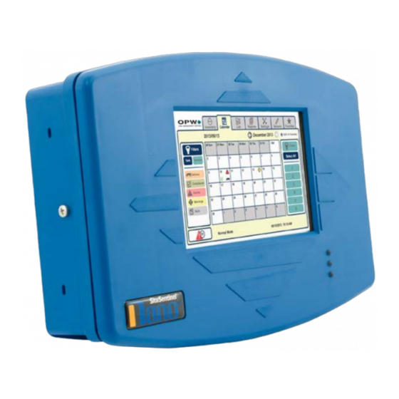
Doc. No.: M2010-EU Rev.: 13 Page 15 of 149 ® ® Section 2 SiteSentinel Nano Console ® ® The SiteSentinel Nano console can monitor up to 12, 924B Tank-Probes and has two (2) relays that can be used at the same time. Since only AC power connections and Petro-Net communication connections are necessary, the console can be installed in many locations of a fueling facility.
-
Page 16: Console Specifications
Doc. No.: M2010-EU Rev.: 13 Page 16 of 149 2.2 Console Specifications Console Specifications Power: 120/240 VAC +/- 10%, 50/60 Hz, 30 W Relay Contacts: 250V AC 10A Max. Operating Temperature: 0°C to 50°C (32°F to 122°F) 21 cm x 32.5 cm x 6 cm (8.3 inches x 12.8 inches x 2.4 Console Dimensions [H x W x D]: inches) 17.8 cm (7 inches) color LCD touch screen display Graph-…
-
Page 17: Console Installation
Doc. No.: M2010-EU Rev.: 13 Page 17 of 149 2.3 Console Installation 2.3.1 Installation Instructions 1. Select an area to install the SiteSentinel® Nano® console on a wall in a safe indoor location. The display must be at approximately eye level and easily seen. a.
-
Page 18
Doc. No.: M2010-EU Rev.: 13 Page 18 of 149 NOTICE: Make sure to remove the main board and put it in a static-free area before you go to the next step. This will prevent damage to the main board components when you remove the knockouts. -
Page 19: Installation Video
Doc. No.: M2010-EU Rev.: 13 Page 19 of 149 2.3.2 Installation Video Scan the code below or click the link to see the video, «Installation of an OPW Nano Tank Gauge.» https://www.youtube.com/watch?v=qPZAe5_oWVk&feature=youtu.be IMPORTANT: Make sure the electrical wiring is connected on the left side of the console and the Tank-Probe and Smart-Sensor wiring is connected on the right side.
-
Page 20
Doc. No.: M2010-EU Rev.: 13 Page 20 of 149 Main Board Connections, Jumpers and LEDs… -
Page 21
Doc. No.: M2010-EU Rev.: 13 Page 21 of 149 Conduit Installation… -
Page 22
Doc. No.: M2010-EU Rev.: 13 Page 22 of 149 Field Wiring Diagram… -
Page 23: Console And Peripheral Connections
Doc. No.: M2010-EU Rev.: 13 Page 23 of 149 2.5 Console and Peripheral Connections 2.5.1 Direct Connections ® ® NOTE: The SiteSentinel Nano console comes with a given IP address. Do not change this address if you use a crossover cable. To make a wired connection between the console and a PC, a standard RJ45 crossover cable is necessary.
-
Page 24: Section 3 Om4 Output Module
Doc. No.: M2010-EU Rev.: 13 Page 24 of 149 Section 3 OM4 Output Module OM4 Output Module The OM4 Output Module has four (4) relay positions. Four (4) OM4 units can be connected together for a ™ total of 16 relays. The wiring instruction on the inside of the OM4 shows the correct Petro-Net communications and power connections.
-
Page 25: Safety Precautions
Doc. No.: M2010-EU Rev.: 13 Page 25 of 149 3.1 Safety Precautions WARNING: DO NOT connect the OM4 output Module directly to a submersible pump! The OM4 controls pumps INDIRECTLY, through relays or contactors. There can be high voltages in the OM4. Servicing of the unit must only be done by an approved technician.
-
Page 26: Om4 Technical Specifications
Doc. No.: M2010-EU Rev.: 13 Page 26 of 149 3.4 OM4 Technical Specifications OM4 Technical Specifications Field Wiring Rating: 105°C, 600V Type RH. TW, RFH-2 or equivalent Power Requirements: 12 VAC, 0.5A Max. Dimensions (W x H x D): 15 cm x 15 cm x 10 cm (6” x 6” x 4”) Temperature Rating: 0°C –…
-
Page 27: Petro-Net Address Jumper Settings
Page 27 of 149 NOTE: The Petro-Net twisted pair cable (OPW-FMS p/n 12-1029) can connect to the console and to other devices that support the Petro-Net over RS485 protocol. Maximum length for all parallel connected devices is 5,000 feet (1524 meters). Petro-Net polarity must be kept for the console and all devices through the entire system.
-
Page 28
Doc. No.: M2010-EU Rev.: 13 Page 28 of 149 Attach and tighten the nuts. OM4 Jumper Settings for Multiple OM4 Operation… -
Page 29: Section 4 Tank Alert (Overfill Alarm)
Doc. No.: M2010-EU Rev.: 13 Page 29 of 149 Section 4 Tank Alert (Overfill Alarm) ® ® The SiteSentinel Nano can use one of its internal output contacts or an output relay of a connected OM4 Module to cause an overfill alarm condition in a connected Tank Alert. The Tank Alert has a buzzer and an external light to tell you of an overfill condition or high-product alarm.
-
Page 30: Tank Alert Specifications
Doc. No.: M2010-EU Rev.: 13 Page 30 of 149 4.2 Tank Alert Specifications Tank Alert Specifications – 120V Voltage: 120 VAC, 50/60 Hz Enclosure Dimensions (H x W x D): 6.5 x 4.5 x 3 inches (16.51 x 11.43 x 7.62 cm) Alarm Horn: Alarm Horn: 85 decibels at 10 feet (3 meters) Alarm Beacon:…
-
Page 31: Tank Alert Installation
Doc. No.: M2010-EU Rev.: 13 Page 31 of 149 4.3 Tank Alert Installation The Tank Alert can be installed in a building or an outdoor location. Two (2) #8 x 1.25 self-tapping screws and sealing washers are included with the Tank Alert. Select an installation location over a wall stud or use wall anchors.
-
Page 32
Doc. No.: M2010-EU Rev.: 13 Page 32 of 149… -
Page 33: Section 5 Probe Installation Preparation
Doc. No.: M2010-EU Rev.: 13 Page 33 of 149 Section 5 Probe Installation Preparation This section shows the procedures necessary for installation of tank-probes that will be connected to your Nano console. Topics in this section include: «Probe Placement» on the next page «Product Offset Calculation»…
-
Page 34: Probe Placement
Doc. No.: M2010-EU Rev.: 13 Page 34 of 149 5.1 Probe Placement CAUTION: Model 924B and DMP probes must be installed as shown in this section. If the installation cannot be done with the minimum or maximum dimensions specified, do not continue with the installation. Model 924B and DMP probes are safe for Class 1, Div 1, Group D hazardous locations.
-
Page 35: Product Offset Calculation
Doc. No.: M2010-EU Rev.: 13 Page 35 of 149 5.2 Product Offset Calculation It is possible to calculate product offset for a probe that is not installed in the center of a «pitched» tank. Pitch occurs when a tank is installed tilted along its horizontal axis. Some tanks are installed with one end lower than the other to let water and sediment collect at the low end, so that clear product can be pulled from the high end.
-
Page 36: Riser, Manhole And Junction Box Installation
NOTE: The probe cap and adapter kit below can only be used for the OPW-FMS 924B probe. For DMP probes, use an applicable riser cap with a 9.50 mm cable gland. OPW-FMS recommends to use the OPW 62M Monitor Probe Cap & Adapter Kit (P/N 30-0219). The…
-
Page 37: Manhole And Junction Box
NOTE: The 924B probe cable (OPW P/N 10-1185) is 6 feet (1.83 M) in length. Make sure there is sufficient length of cable from the probe to where a weatherproof junction box is to be installed.
-
Page 38
Doc. No.: M2010-EU Rev.: 13 Page 38 of 149 924B Probe Installation DMP Probe Installation… -
Page 39: Conduit Seal Fittings For Cables
Doc. No.: M2010-EU Rev.: 13 Page 39 of 149 5.4 Conduit Seal Fittings for Cables IMPORTANT: To comply with Article 501 of the National Elecrical Code, Seal-offs must be installed where I.S. wiring enters conduit. Install one conduit seal fitting in the manhole where the conduit leaves the junction box and one in the building before the conduit goes into the console.
-
Page 40
CAUTION: The console must have a dedicated power circuit and must be on the same phase as all other OPW equipment. Only OPW probe cables and sensor wiring can be in the same conduit that goes to the I.S. barriers. -
Page 41
Doc. No.: M2010-EU Rev.: 13 Page 41 of 149… -
Page 42: Probe Installation In Underground Storage Tanks
The probe cable (OPW P/N 10-1185) is 6 feet (1.83 M) in length. Make sure there is sufficient length of cable from the probe to where a weatherproof junction box is to be installed.
-
Page 43: Nano Mixed Multi-Drop Installation
NOTE: The OPW-FMS model 924B probe and the DMP probe can be on the same internal Nano I.S. barrier position for multi-drop installations. The two probes are equal to the same point values to calculate the mix of probes and sensors on a barrier position.
-
Page 44: Section 6 924B Probe Installation
Doc. No.: M2010-EU Rev.: 13 Page 44 of 149 Section 6 924B Probe Installation 6.1 Probe Floats There are three types of floats used with the probes: Product, Water for Diesel, and Water for Gasoline. IMPORTANT: The two types of water floats are NOT interchangeable. Because diesel has more density than gasoline, the diesel floats are heavier than the gasoline floats.
-
Page 45: Model 924B Probe Specifications
Class I, Division 1, Group D IECEx UL 11.0012X Certifications: DEMKO 11 ATEX 1012670X I.S. Barrier Used: 12V ONLY; OPW P/N: 20-4344 (Green Label) 924B is the only probe that can be multi-dropped at a maximum of four Multi-drop Restriction**: (4) probes per channel Connections:…
-
Page 46
Doc. No.: M2010-EU Rev.: 13 Page 46 of 149 NOTE: **ONLY 924B Probes made after September 1, 2007, (version 7.xx firmware) can be installed in a multi-drop installation. -
Page 47: Waterproof Electrical Connections
Page 47 of 149 6.3 Waterproof Electrical Connections Components Each 924B Tank-Probe and OPW-FMS Smart-Sensor wiring kit will have all the necessary components to complete the seal-pack assembly for electrical connections. Each kit includes: Three (3) wire-nuts Two (2) cable tie wraps ™…
-
Page 48
Doc. No.: M2010-EU Rev.: 13 Page 48 of 149 Instructional Video If you have a QR code scanner or reader app for your smartphone you can scan this code (or click the link) to Multidrop Probe and Sensor Wiring Instructions see the instruction video, Multidrop Probe and Sensor Wiring Instructions Safety Information… -
Page 49
Doc. No.: M2010-EU Rev.: 13 Page 49 of 149 Assembly Procedure ™ To assemble the wire connections and Scotchcast resin seal-packs: Assemble the Epoxy Seal Pack for Waterproof Electrical Connections NOTICE: It is VERY important to seal all Tank-Probe and Smart-Sensor connections in the junction box to prevent corrosion of the wires. -
Page 50
When you remove the insulation from the cables or conductors be careful to not cut the metal wires inside the insulation material. NOTE: The photo in the procedure above shows wiring for OPW-FMS 924B Tank-Probes. The inner conductor wires in the Smart-Sensor cables are different colors. Refer to the… -
Page 51
Doc. No.: M2010-EU Rev.: 13 Page 51 of 149 CAUTION: Always wear protective gloves and safety glasses when you do work with the epoxy resin packs! 9. Prepare the epoxy resin seal-pack. Bend the package until the separation between the two resins breaks. Mix the two (2) resins together fully for approximately two (2) minutes. -
Page 52
Doc. No.: M2010-EU Rev.: 13 Page 52 of 149 Mixed Multi-drop Field Wiring The Nano console can accept Mixed Multi-drop Field Wiring. Tank-Probes and Smart-Sensors can be wired Mixed Multi-drop on the same Field Wiring cable to the same I.S. barrier channel. Refer to the Section Installation for the limits on the number of probes and sensors that can be on a barrier channel. -
Page 53: Section 7 Dover Magnetostrictive Probe (Dmp)
Doc. No.: M2010-EU Rev.: 13 Page 53 of 149 Section 7 Dover Magnetostrictive Probe (DMP) The Dover Magnetostrictive Probe (DMP) is installed almost the same as a 924B Probe. 7.1 DMP Probe Installation IMPORTANT: To prevent damage to the probe, be careful when you remove the probe from its packaging and when you install it in a tank.
-
Page 54
Doc. No.: M2010-EU Rev.: 13 Page 54 of 149 4. Carefully put the assembled probe down through the riser into the tank until the probe end cap touches the bottom of the tank. NOTICE: Carefully lower the probe down into the tank. To prevent damage to the probe, do not let the probe fall and hit the bottom of the tank wall. -
Page 55: Spacer Assembly (6-3/4 Ra Ss) And Adjustment
Doc. No.: M2010-EU Rev.: 13 Page 55 of 149 7.2 Spacer Assembly (6-3/4 RA SS) and Adjustment IMPORTANT: The minimum inner diameter for a riser is 52 mm (2.05 in.). This gives an allowance for the head gaskets so the probe can move freely inside the riser The DMP Probe can be installed in a minimum 52 mm (2.05 in.) inner diameter riser without modification.
-
Page 56: Dmp Probe Cable Wiring To Nano I.s. Barrier
Doc. No.: M2010-EU Rev.: 13 Page 56 of 149 NOTICE: Be careful to not cause damage to the probe label when you install or when you make adjustments to the spacer. The label contains important safety and product information. To assemble and adjust the probe spacer: 1.
-
Page 57: Section 8 Density Measurement Float (Dmf)
Page 57 of 149 Section 8 Density Measurement Float (DMF) OPW Part Number 20-4431 (Gas — White Core) & 20-4432 (Diesel — Black Core) The Density Measurement Float (DMF) can be installed on a pre-existing probe. The DMF continuously measures the average density of the fuel in the tank. This can measure the smallest change in product density in the API density range.
-
Page 58: Dmf Installation
Doc. No.: M2010-EU Rev.: 13 Page 58 of 149 Product Density and Chemical Compatibility Product Group Compatibility Specific Gravity Gasoline Aviation Gasoline Regular Unleaded Gasoline Regular Leaded 45 < API < 78 0.68 < d < 0.80 Premium Unleaded Gasoline/Methanol blend, less than 5% methanol Gasohol, less than 40% ethanol Diesel Jet Fuel…
-
Page 59: Tank Thresholds
Doc. No.: M2010-EU Rev.: 13 Page 59 of 149 ® ® For DMF configuration and calibration refer to your M2011 SiteSentinel Nano Configuration Guide. You will need the A and B Factors that are etched into the body of the float. See the image below. NOTICE: The Density Measurement Float is not to be used in a pressurized tank.
-
Page 60: Section 9 Sensor Support
Nano system supports OPW-FMS Smart Sensors that use IntelliSense Technology. The OPW smart sensors can monitor all contained areas of the fuel-storage system: tank interstice, piping sumps, STP containment sumps, dispenser sumps and pans, monitoring wells and site locations. Sensors connected to the I.S. barrier are automatically detected and identified by the console.
-
Page 61
Doc. No.: M2010-EU Rev.: 13 Page 61 of 149 Part Number Description 30-0230-S Liquid Only Float Sensor (Brass) — steel tank interstitial containment area 30-0232-D-10 Dual Float Non-Discriminating Dispenser Sump Sensor 30-0232-D-20 Dual Float Non-Discriminating STP Sump Sensor 30-0232-D-10B Dual Float Brine Sensor for Containment Sump 30-0232-D-20B Dual Float Brine Sensor for Fiberglass Tanks 30-0235-V… -
Page 62: Discriminating Dispenser Sump/Stp Sump Sensor
Doc. No.: M2010-EU Rev.: 13 Page 62 of 149 9.4 Discriminating Dispenser Sump/STP Sump Sensor Smart Sensor Equipped with Intellisense™ Technology 30-0232-DH-10 & 30-0232-DH-20 Description IMPORTANT: This float body is the same as the 30-0232-D10 / D20 and 30-0232-D-10B / D- 20B.
-
Page 63
Doc. No.: M2010-EU Rev.: 13 Page 63 of 149 Cutaway View of Sensor that Shows Internal Floats Specifications DH-10: Fuel Dispenser Pan/Sump Primary Use(s): DH-20: STP Sumps DH-10: STP Sumps Alternate Uses: DH-20: Fuel Dispenser Pan/Sump Detects: Low Liquid, High Liquid, Fuel Operating Temperature: -40°C to +70°C (-40°F to 158°F) DH-10 Dimensions:… -
Page 64
Installation IMPORTANT: This Smart Sensor must ONLY be connected to an OPW Fuel Management Systems 12V VSmart Module. This will make sure that operation conditions are safe. Smart Sensors CANNOT be used with SS1, 2 or 3, iTouch or EECO consoles. -
Page 65
Doc. No.: M2010-EU Rev.: 13 Page 65 of 149 Connect the sensor wires to the field wires in the junction box. Use the supplied cable gland and silicon wire nuts. M00-390008 Waterproof Electrical Seal the electrical connections with the epoxy seal packs (refer to Connections for instructions). -
Page 66
It is recommended to only do the procedures below when it becomes necessary and only as a last alternative. These procedures can cause a decrease in the original electrical resistance of the polymer. If possible, speak with a certified OPW-FMS technician before you do these procedures. -
Page 67
Doc. No.: M2010-EU Rev.: 13 Page 67 of 149 The test is satisfactory if an alarm condition or other event related to the hydrocarbon part of the sensor occurs. If the test results are unsatisfactory, replace the sensor. Functional Test — Water Sensor of the Device TAP water Put the end of the sensor fully into for at least two (2) minutes. -
Page 68: Discriminating Interstitial Sensor (Optical)
Doc. No.: M2010-EU Rev.: 13 Page 68 of 149 9.5 Discriminating Interstitial Sensor (Optical) Smart Sensor Equipped with Intellisense™ Technology 30-0236-LW Description The primary function of the Discriminating Interstitial Optical Liquid Sensor is to monitor the interstitial area of double-walled tanks. This sensor uses a long-life, solid-state optical prism. These sensors can also be used in sumps, fuel dispenser pans and other locations where there is liquid that could indicate that a leak has occurred.
-
Page 69
Installation IMPORTANT: This Smart Sensor must ONLY be connected to an OPW Fuel Management Systems 12V VSmart Module. This will make sure that operation conditions are safe. Smart Sensors CANNOT be used with SS1, 2 or 3, iTouch or EECO consoles. -
Page 70
Doc. No.: M2010-EU Rev.: 13 Page 70 of 149 Measure the length of the circular space in the monitoring pipe from top to bottom and subtract 1.3 cm (0.5 in.) for a total measurement to be used for the sensor installation. Measure the calculated length from the sensor tip along the sensor cable and identify it with tape or a marker. -
Page 71
Doc. No.: M2010-EU Rev.: 13 Page 71 of 149 Typical Installation Drawing Controller Setup The sensor must be Auto Detected on the console (Refer to the M2011 Nano Configuration Guide ). Alarm Intellisense thresholds are configured automatically through the mechanism between the sensor and the console. -
Page 72
Doc. No.: M2010-EU Rev.: 13 Page 72 of 149 Test the Optical Sensor CAUTION: Use caution to prevent dangerous conditions when you do work in a hazardous area. Make sure that the area has sufficient airflow when you do a test or remove contamination from the sensor. -
Page 73: Hydrocarbon Liquid Sensor With Water Indicator
Doc. No.: M2010-EU Rev.: 13 Page 73 of 149 9.6 Hydrocarbon Liquid Sensor with Water Indicator Smart Sensor Equipped with Intellisense™ Technology 30-0234-HW-06, -15, -20 Description The primary function of the Hydrocarbon Liquid Sensor with Water Indicator is to monitor wet wells with groundwater tables that can change levels.
-
Page 74
Installation IMPORTANT: This Smart Sensor must ONLY be connected to an OPW Fuel Management Systems 12V VSmart Module. This will make sure that operation conditions are safe. Smart Sensors CANNOT be used with SS1, 2 or 3, iTouch or EECO consoles. -
Page 75
It is recommended to only do the procedures below when it becomes necessary and only as a last alternative. These procedures can cause a decrease in the original electrical resistance of the polymer. If possible, speak with a certified OPW-FMS technician before you do these procedures. -
Page 76
Doc. No.: M2010-EU Rev.: 13 Page 76 of 149 CAUTION: Use caution to prevent dangerous conditions when you do work in a hazardous area. Make sure that the area has sufficient airflow when you do a test or remove contamination from the sensor. Make sure there are no open flames or hot surfaces near the work area. -
Page 77
Doc. No.: M2010-EU Rev.: 13 Page 77 of 149 Make sure the sensor is disconnected. Put the dirty part of the sensor fully into denatured alcohol for one (1) hour. Flush the sensor with water to remove all remaining contamination. Let the sensor dry in the air for one (1) hour. -
Page 78: Interstitial Hydrocarbon Liquid Sensor With Water Indicator
Doc. No.: M2010-EU Rev.: 13 Page 78 of 149 9.7 Interstitial Hydrocarbon Liquid Sensor with Water Indicator Smart Sensor Equipped with Intellisense™ Technology 30-0234-HW-01 Description The primary function of the Interstitial Hydrocarbon Liquid with Water Indicator Sensor is to sense liquid hydrocarbons and water in the interstitial area of a double-walled tank.
-
Page 79
Installation IMPORTANT: This Smart Sensor must ONLY be connected to an OPW Fuel Management Systems 12V VSmart Module. This will make sure that operation conditions are safe. Smart sensors CANNOT be used with SS1, 2 or 3, iTouch or EECO consoles. -
Page 80
Doc. No.: M2010-EU Rev.: 13 Page 80 of 149 Typical Installation Drawing Controller Setup Auto Detected M2011 Nano Configuration Guide The sensor must be on the console (Refer to the ). Alarm thresholds are configured automatically through the Intellisense mechanism between the sensor and the console. -
Page 81
Doc. No.: M2010-EU Rev.: 13 Page 81 of 149 Interstitial Hydrocarbon Liquid Sensor with Water Indicator — Functional Test and Remove Contamination CAUTION: Use caution to prevent dangerous conditions when you do work in a hazardous area. Make sure that the area has sufficient airflow when you do a test or remove contamination from the sensor. -
Page 82
Doc. No.: M2010-EU Rev.: 13 Page 82 of 149 If the controller does not sense the alarm conditions simulated by these tests, look to see if the thresholds and alarms are correctly programmed in the system. A sensor or wiring fault will cause a system alarm. Do a continuity test in the wiring and junction boxes. -
Page 83: Interstitial Level Sensor
Doc. No.: M2010-EU Rev.: 13 Page 83 of 149 9.8 Interstitial Level Sensor Smart Sensor Equipped with Intellisense™ Technology 30-0230-S Liquid Only Float Sensor (Brass) & 30-0231-S Interstitial Sensor-Float Switch Description The primary function of these sensors is to sense liquid in the interstitial area of a double-walled steel tank (these sensors are not for use in a double-walled fiberglass tank).
-
Page 84
Installation IMPORTANT: This Smart Sensor must ONLY be connected to an OPW Fuel Management Systems 12V VSmart Module. This will make sure that operation conditions are safe. Smart Sensors CANNOT be used with SS1, 2 or 3, iTouch or EECO consoles. -
Page 85
Doc. No.: M2010-EU Rev.: 13 Page 85 of 149 NOTE: If this sensor is used to monitor a normally dry well, use a meter to set the float position so the sensor is in a closed position when there is NO liquid level (the float will be in the lower position). -
Page 86
Doc. No.: M2010-EU Rev.: 13 Page 86 of 149 Typical Installation Drawings 30-0230-S… -
Page 87
Doc. No.: M2010-EU Rev.: 13 Page 87 of 149 30-0231-S Controller Setup The sensor must be Auto Detected on the console (Refer to the M2011 Nano Configuration Guide ). Alarm Intellisense thresholds are configured automatically through the mechanism between the sensor and the console. -
Page 88
Doc. No.: M2010-EU Rev.: 13 Page 88 of 149 Float Sensor Test CAUTION: Use caution to prevent dangerous conditions when you do work in a hazardous area. Make sure that the area has sufficient airflow when you do a test or remove contamination from the sensor. -
Page 89: Single Level Sump Sensor-Float Switch
Doc. No.: M2010-EU Rev.: 13 Page 89 of 149 9.9 Single Level Sump Sensor-Float Switch Smart Sensor Equipped with Intellisense™ Technology 30-0231-L Description The primary function of the single-level sensor is to sense liquid in sumps, fuel dispenser pans and other locations where there is liquid that could indicate that a leak has occurred.
-
Page 90
Installation IMPORTANT: This Smart Sensor must ONLY be connected to an OPW Fuel Management Systems 12V VSmart Module. This will make sure that operation conditions are safe. Smart Sensors CANNOT be used with SS1, 2 or 3, iTouch or EECO consoles. -
Page 91
Doc. No.: M2010-EU Rev.: 13 Page 91 of 149 This sensor uses ONE Controller Interface I.S. Module position Start with the Connections table and “Typical Installation» drawing below. Make sure the sump pit or pan is dry. Install the sensor on the bottom of the sump/pan. Attach the sensor wire to a pipe or bracket with a tie wrap. -
Page 92
Doc. No.: M2010-EU Rev.: 13 Page 92 of 149 Controller Setup Auto Detected M2011 Nano Configuration Guide The sensor must be on the console (Refer to the ). Alarm Intellisense thresholds are configured automatically through the mechanism between the sensor and the console. -
Page 93: Dual Float Non-Discriminating Sensors
Doc. No.: M2010-EU Rev.: 13 Page 93 of 149 9.10 Dual Float Non-Discriminating Sensors Smart Sensor Equipped with Intellisense™ Technology 30-0232-D-10 Dispenser Sump Sensor & 30-0232-D-20 STP Sump Sensor Description IMPORTANT: This float body is the same as the 30-0232-D-10B / D-20B and 30-0232-DH- 10 / DH-20 (DH-XX has a carbon-polymer strip in the bottom).
-
Page 94
Installation IMPORTANT: This Smart Sensor must ONLY be connected to an OPW Fuel Management Systems 12V VSmart Module. This will make sure that operation conditions are safe. Smart Sensors CANNOT be used with SS1, 2 or 3, iTouch or EECO consoles. -
Page 95
CAUTION: ALWAYS obey Local and National Electrical Codes applicable to the installation location. Make sure that the cables (gas and oil resistant OPW Fuel Management Systems part # 12-1030) from the field wiring to the controller are in conduit that is dedicated to intrinsically safe wiring. -
Page 96
Doc. No.: M2010-EU Rev.: 13 Page 96 of 149 Typical Installation Drawing Controller Setup Auto Detected M2011 Nano Configuration Guide The sensor must be on the console (Refer to the ). Alarm thresholds are configured automatically through the Intellisense mechanism between the sensor and the console. -
Page 97
Doc. No.: M2010-EU Rev.: 13 Page 97 of 149 Put the float back in the HIGH position. Make sure that the controller is not in an alarm condition. If the controller does not go into an alarm condition, look to see if the thresholds are correctly programmed in the system. -
Page 98: Dual Float Brine Sensors
Doc. No.: M2010-EU Rev.: 13 Page 98 of 149 9.11 Dual Float Brine Sensors Smart Sensor Equipped with Intellisense™ Technology 30-0232-D-10B (for Containment Sump) and 30-0232-D-20B (for Fiberglass Tanks) Description IMPORTANT: This float body is the same as the 30-0232-D-10 / D-20 and 30-0232-DH-10 / DH-20 (DH-XX has a carbon-polymer strip in the bottom).
-
Page 99
Doc. No.: M2010-EU Rev.: 13 Page 99 of 149 Cutaway View of Sensor Showing Internal Floats Specifications Primary Use: Measure the level of brine solution Detects: Low Liquid, High Liquid Operating Temperature: -40°C to +70°C (-40°F to 158°F) D-10B Dimensions: Diameter: 5.8 cm (2.3 in.), Length: 28.2 cm (11.1 in.) D-20B Dimensions: Diameter: 5.8 cm (2.3 in.), Length: 53.6 cm (21.1 in.) -
Page 100
Installation IMPORTANT: This Smart Sensor must ONLY be connected to an OPW Fuel Management Systems 12V VSmart Module. This will make sure that operation conditions are safe. Smart Sensors CANNOT be used with SS1, 2 or 3, iTouch or EECO consoles. -
Page 101
Doc. No.: M2010-EU Rev.: 13 Page 101 of 149 Typical Installation Drawing Controller Setup The sensor must be Auto Detected on the console (Refer to the M2011 Nano Configuration Guide ). Alarm Intellisense thresholds are configured automatically through the mechanism between the sensor and the console. -
Page 102
Doc. No.: M2010-EU Rev.: 13 Page 102 of 149 Float Sensor Test CAUTION: Use caution to prevent dangerous conditions when you do work in a hazardous area. Make sure that the area has sufficient airflow when you do a test or remove contamination from the sensor. -
Page 103: Hydrocarbon Vapor Sensor
Doc. No.: M2010-EU Rev.: 13 Page 103 of 149 9.12 Hydrocarbon Vapor Sensor Smart Sensor Equipped with Intellisense™ Technology 30-0235-V Description The primary function of the Hydrocarbon Vapor Sensor is to sense hydrocarbon vapors in monitoring wells and the interstitial areas of a double-walled tank. These vapors could indicate a possibly dangerous leak that could lead to safety and environmental problems.
-
Page 104
Installation IMPORTANT: This Smart Sensor must ONLY be connected to an OPW Fuel Management Systems 12V VSmart Module. This will make sure that operation conditions are safe. Smart Sensors CANNOT be used with SS1, 2 or 3, iTouch or EECO consoles. -
Page 105
Doc. No.: M2010-EU Rev.: 13 Page 105 of 149 Install the sensor close to the top, above the water level, if applicable (if the sensor is under water it will not operate). Connect the sensor cable to the sensor. Connect the sensor wires to the field wires in the junction box. Use the supplied cable gland and silicon wire nuts. -
Page 106
Doc. No.: M2010-EU Rev.: 13 Page 106 of 149 Typical Installation Drawing Controller Setup Auto Detected M2011 Nano Configuration Guide The sensor must be on the console (Refer to the ). Alarm Intellisense thresholds are configured automatically through the mechanism between the sensor and the console. -
Page 107
Doc. No.: M2010-EU Rev.: 13 Page 107 of 149 Test the Hydrocarbon Vapor Sensor CAUTION: Use caution to prevent dangerous conditions when you do work in a hazardous area. Make sure that the area has sufficient airflow when you do a test or remove contamination from the sensor. -
Page 108: Appendix A — Model 924B Probe Part Numbers
Doc. No.: M2010-EU Rev.: 13 Page 108 of 149 Appendix A — Model 924B Probe Part Numbers Model 924B Probe Part Numbers Length Part Probe Length Description (inches) (cm) Number Mag Probe for 122 cm (4 feet) Diameter/Height Tank 30-B053 Mag Probe for 152 cm (5.5 feet) Diameter/Height Tank 30-B069 Mag Probe for 183 cm (6 feet) Diameter/Height Tank…
-
Page 109: Appendix B — Probe Installation Records
Doc. No.: M2010-EU Rev.: 13 Page 109 of 149 Appendix B — Probe Installation Records Barrier Position (1-4) Probe Tank Internal Product in Tank (Number in Chain, Serial Number Number Barrier # if applicable 1-4)
-
Page 110: Appendix C — Declaration Of Conformity
Doc. No.: M2010-EU Rev.: 13 Page 110 of 149 Appendix C — Declaration of Conformity…
-
Page 111
Doc. No.: M2010-EU Rev.: 13 Page 111 of 149… -
Page 112
Doc. No.: M2010-EU Rev.: 13 Page 112 of 149… -
Page 113
Doc. No.: M2010-EU Rev.: 13 Page 113 of 149… -
Page 114: Appendix D — Nwglde Evaluation
Consistent testing at low levels could allow a leak to remain undetected. EPA leak detection regulations require testing of the portion of the tank system which routinely contains product. 2012 console comparison with OPW iSite; which was based on 2-26-2008 evaluation of OPW iSite. OPW Fuel Management Systems 6900 Santa Fe Dr.
-
Page 115: Appendix E — Pro Gauge Probe Installation
ProGauge probes cannot be connected to the internal I.S. barrier of the OPW- FMS SiteSentinel NANO. The XMT-SI-RF wireless probe first sends a signal to an RF Receiver that will then communicate with the NANO through an RS485 serial connection. The appendices that follow will give all of the necessary information on the installation of these devices.
-
Page 116
Doc. No.: M2010-EU Rev.: 13 Page 116 of 149 Measurement Characteristics Electronics based on a Microprocessor Support telediagnostics and telemaintenance Possibility to configure remotely the functional parameters When maintenance is necessary, the internal parts of the probe can be removed and it will not be necessary to remove fuel from the tank. -
Page 117
Doc. No.: M2010-EU Rev.: 13 Page 117 of 149 Riser Preparation for RF Probes Use galvanized pipe with an internal diameter of 2.05 inches (52 mm). Cut the galvanized pipe to the correct size. The riser should cover the probe head while the antenna is kept open at the top. -
Page 118
Doc. No.: M2010-EU Rev.: 13 Page 118 of 149 Carefully install the assembled probe through the riser and flange into the tank. Assemble the Antenna Cover. Put the cover over the antenna. Turn clockwise to tighten the cover. Make sure that the seal between the cover and the brown gasket is tight. Do not over-tighten as this could cause damage to the threads. -
Page 119
Doc. No.: M2010-EU Rev.: 13 Page 119 of 149 Install the PA 2 inch protective sleeve (purchased option when the XMT-SI-RF is installed in a riser). Apply a thread sealant to the male threads of the riser and the female sleeve flange and between the male threads of the PA2 and the female sleeve flange. -
Page 120
Doc. No.: M2010-EU Rev.: 13 Page 120 of 149 Jumper Setting Jumper settings are shown below. The Jumpers are read during device startup. When changes are made, the device must be switched off and restarted for the changes to be applied. Jumper Inserted Removed… -
Page 121
Doc. No.: M2010-EU Rev.: 13 Page 121 of 149 DIP-Switch settings are shown below. The DIP-Switches are read during device startup. When changes are made, the device must be switched off and restarted for the changes to be applied. To optimize battery life, the probe usually operates in Sleep Mode. The probe will be started at the time increment set by the selected Operation Mode and will make its measurement. -
Page 122
Doc. No.: M2010-EU Rev.: 13 Page 122 of 149 NOTE: This feature lets you do a check of the signal and not have to wait for the longer periods of Sleep Mode. This feature is not available for Operation Modes 12 — 16. XMT-SI-RF DIP-Switch Configuration, Operation Modes and Bat- tery Life Battery Life (in years) at… -
Page 123
Use of a type of battery other than that specified by the manufacturer will compromise the Intrinsically Safe certification. OPW-FMS, Tokheim/Pro Gauge or Start Italiana cannot be held responsible for equipment failures or safety issues related to use of an non-certified battery. -
Page 124
Doc. No.: M2010-EU Rev.: 13 Page 124 of 149 Important Battery Information DANGER: Because of new Federal Regulations, all lithium batteries are Class 9 Hazmat. Lithium batteries must be shipped on a separate order or purchased separately. Use only a SAFT LS33600 in this device. The lithium battery can cause fire or explosion if they are not used correctly. -
Page 125: Appendix F — Progauge Rf Receiver
Doc. No.: M2010-EU Rev.: 13 Page 125 of 149 Appendix F — ProGauge RF Receiver The ProGauge RF Receiver lets the ProGauge XMT-SI-RF probe interface with the OPW-FMS SiteSentinel Nano console. The RF Receiver device can receive wireless probes model XMT-SI-RF 169,4 MHz…
-
Page 126
White Terminal, GND — CN1 position 4 Red terminal, +Vcc — CN1 position 1 RS485 Connection Blue Data RS485 A — CN1 position 3 Brown Data RS485 B — CN1 position 2 NOTE: OPW-FMS Petro-Net can also be used for RS485 connections. -
Page 127
Doc. No.: M2010-EU Rev.: 13 Page 127 of 149 High Gain Harmattan 169 MHz Antenna ELECTRICAL Frequency range: (V.S.W.R. < 2 : 1) 162-174 MHz Impedance: 50 Ω V.S.W.R. at 169 Mhz: < 2 : 1 Max power: 15 W Polarization: Linear Irradiation:… -
Page 128
Doc. No.: M2010-EU Rev.: 13 Page 128 of 149 Antenna Installation Each antenna has its own radiation diagram. The radiation diagram shows the directions where the antenna can transmit the signal with the most power. The diagrams below show the directional patterns of the probe antenna and the receiver antenna. To have the best reception without signal loss, the antennas must be pointed in the same direction. -
Page 129
Doc. No.: M2010-EU Rev.: 13 Page 129 of 149 Those made completely of iron A reinforced concrete square with welded mesh. Common manhole constructions that do not block signal transmission like a Faraday Cage include: A standard manhole with an iron or cast iron lead cover. A manhole of bricks. -
Page 130
Doc. No.: M2010-EU Rev.: 13 Page 130 of 149 Installer RF Probe Determination Worksheet Installer Notes: (to find out if RF Topic Condition Probes are possible before installation) Environment Depot or Service Station? Material Type (iron, cast iron, composite…): Manhole Depth: Installation with: Riser or Sliding Connection? Manhole Moveable or isolated? -
Page 131
Doc. No.: M2010-EU Rev.: 13 Page 131 of 149 LED Diagnostics LED Diagnostic Functions LED Label Function Behavior On startup, refers to Must flash and indicates that the board is working properly. RUN. Wired on RX line of Flashing indicates that a valid frame has been received by the 169,4MHz mod- the module and transmitted to the microprocessor. -
Page 132
Doc. No.: M2010-EU Rev.: 13 Page 132 of 149 DIP-Switch Settings RF Receiver Board DIP-Switch Binary Combinations Setting 1 (Default) -
Page 133
Doc. No.: M2010-EU Rev.: 13 Page 133 of 149 Setting 1: Normal functioning, answers through the new protocol both on RS485 and RS232. EXAMPLE: D) M03744+chr(13) R) 03744N0=+250=00129.37=00031.00=082+chr(10)+chr(13) Probe address: 03744 Probe status: (0 = OK) in case of error status=1 Temperature: +25,0 °C Product level: 129,37 mm Water level: 31,00 mm… -
Page 134
Doc. No.: M2010-EU Rev.: 13 Page 134 of 149 Setting 3: Inside the receiver, 10.000 is added to the wireless probe address, answers through the new protocol both on RS485 and RS232. Use this setting when two (2) receivers are installed for maximum signal coverage. The two receivers must be connected in parallel on the RS485 line. -
Page 135
Doc. No.: M2010-EU Rev.: 13 Page 135 of 149 Setting 8: Repeater mode: Everything received on the radio channel is always immediately retransmitted on the radio channel. Transmission always done with frame recognition: The receiver waits with a silence of at least 20 ms on the radio channel. -
Page 136
Doc. No.: M2010-EU Rev.: 13 Page 136 of 149 Available Commands Speed 9600 Data bits: 8 Parity bit: none Stop bit: 1 Command M Asks for the measurement. See the examples above. Command D Asks for the diagnostics. EXAMPLE: D) D14832+chr(13) 14832D105=00000118=00006721=00000118=001=005=200=015=048=113=078=045=100=07 1=197 Probe address: 14832… -
Page 137
Doc. No.: M2010-EU Rev.: 13 Page 137 of 149 Command V Asks for the version. Command C Asks for the list of all the registered probes. EXAMPLE: D) C+chr(13) 03746N0=+290=00105.68=00028.64=102 03967N0=+290=00092.30=00016.32=093 03745N0=+290=00090.78=00015.47=102 03962N0=+280=00090.57=00015.61=095 14832N0=+260=00254.01=00000.00=069 Order Code When you place your order please use these order codes: POWER SUPPLY 24V RECEIVER WITH LOW GAIN ANTENNA: ……..RIC-RF RECEIVER WITH HIGH GAIN HARMATTAN ANTENNA: ..RIC-RF-HARM… -
Page 138: Appendix G — Nano Control Drawing
Doc. No.: M2010-EU Rev.: 13 Page 138 of 149 Appendix G — Nano Control Drawing NOTES: 1. Associated Apparatus Entity Parameters: Group IIA Voc (or Uo) = 14.85Vdc Isc (or Io) = 305mA = 974mW Ca (or Co) = 7.15uF La (or Lo) = 1.52mH 2.
-
Page 139
Doc. No.: M2010-EU Rev.: 13 Page 139 of 149 10. Control equipment must not use or generate more than 250V rms or dc with respect to earth… -
Page 140: Appendix H — 924B Probe Control Drawing
Doc. No.: M2010-EU Rev.: 13 Page 140 of 149 Appendix H — 924B Probe Control Drawing NOTES: 1. Entity Parameters: (Vmax), Ui = 14.9V (Imax), Ii = 362mA Ci = 0uf Li = 363uH For Pi ≤ 1.3W -40°C ≤ Tamb ≤ 40°C For Pi ≤…
-
Page 141
Doc. No.: M2010-EU Rev.: 13 Page 141 of 149 924B entity parameters Associated Apparatus 14.9V (Ui) ≥ 14.28V (Uo) 362mA (Ii) ≥ 361mA (lo) (14.28*0.361)/4 = 1.29W 1.3W (Pi) ≥ (Po) 0uF (Ci)+0.060uF ≤ 6.4uF (Co) (Ccable)=0.060uF 363uH (Li)+200uH ≤ 2,100uH (Lo) (Lcable) = 563uF If the above statements are true (which they are) then it is safe to connect. -
Page 142
Doc. No.: M2010-EU Rev.: 13 Page 142 of 149… -
Page 143: Appendix I — Isim Control Drawing
Doc. No.: M2010-EU Rev.: 13 Page 143 of 149 Appendix I — ISIM Control Drawing NOTES: Description The Intelligent Sensor Interface Module (ISi) allows multiple sensors (maximum of 16) connected to a single cable run and a single barrier position. The equipment is intended for installation in Category 1, Group IIA Hazardous Locations.
-
Page 144
Doc. No.: M2010-EU Rev.: 13 Page 144 of 149 Capacitance of the field wiring from the intrinsically safe equipment to the Associated Apparatus shall be calculated and must be included in the system calculations. Capacitance of the cable is Ccable. When the cable capacitance per foot is not known, the following value shall be used: Ccable = 60pF/ft The ISI, with or without sensor, has a Ci of OuF, so only the capacitance of the field wiring cable need to be totaled and compared with the Associated Apparatus. -
Page 145
Doc. No.: M2010-EU Rev.: 13 Page 145 of 149 The sensor must meet the following criteria: Sensor entity parameters ISI output entity parameters Vmax, Ui ≥ Vt, Uo 14.9V Imax, Ii ≥ lt,lo 148mA ≥ Po 0.56W ≤ Ca, Co 2uF ≤… -
Page 146
Doc. No.: M2010-EU Rev.: 13 Page 146 of 149… -
Page 147
In no event shall manufacturer’s liability on any claim for damages arising out of the manufacture, sale, delivery or use of the goods exceed the original purchase price of the goods. In no event shall OPW Fuel Management Systems be liable for any direct, indirect, incidental or consequential damage or loss of product. -
Page 148
Doc. No.: M2010-EU Rev.: 13 Page 148 of 149 Revision History Revision Software Effective Key Changes Version* 7/18/14 Initial Release Adds UL suggested battery warnings. Add probe/STP graphic update. Add detailed instruction for sec. 5.1 3/3/15 Waterproof Elec Conn. Add density sensor/pressure note Sensor support…S07402 — Main Nano Application 11/6/15…
This manual is also suitable for:
M2010-eu
SITESENTINEL
®
INTEGRA 100™/500™
AUTOMATIC TANK GAUGE SYSTEM
Configuration Manual
www.opwglobal.com
Central Technical Support Number: 1-877-OPW-TECH (877-679-8324)
Calls outside US and Canada: 1-708-485-4200 Fax: 1 (800) 421-3297
Hours: Monday through Friday, 7:00 am to 6:00 pm, US CST
Document Number
: M1801, Rev. 01
Issue Date:
October 25, 2013
Supersedes
: November 5, 2012
2013 Delaware Capital Formation, Inc. All Rights Reserved. DOVER and the DOVER logo are registered trademarks of Delaware Capital Formation, Inc., a wholly owned subsidiary of Dover Corporation.
www.opwglobal.com
Doc. #
: M1801, Rev. 01
Page 2 of 143
Table of Contents
1
Getting Started ………………………………………………………………………………………………………… 6
1.1
1.2
Login ……………………………………………………………………………………………………………….. 6
Cold Start …………………………………………………………………………………………………………. 8
1.2.1
Cold Start Procedure …………………………………………………………………………………… 8
1.3
Module Detection (VSmart, Smart, OM4 and LIM) …………………………………………………. 9
1.4
1.3.1
Level 0 Auto Detection ……………………………………………………………………………….. 12
Device Detection (Probes and Sensors) ……………………………………………………………… 14
1.4.1
Level 1 Auto Detection ……………………………………………………………………………….. 14
1.4.2
Level 2 Auto Detection ……………………………………………………………………………….. 16
2
Address Book ………………………………………………………………………………………………………… 20
3
Site Summary ……………………………………………………………………………………………………….. 24
4
Preferences …………………………………………………………………………………………………………… 26
4.1
System Preferences …………………………………………………………………………………………. 26
4.1.1
Alarm Preferences …………………………………………………………………………………….. 26
4.1.2
Alarm Event Closure ………………………………………………………………………………….. 27
4.2
Tank Preferences …………………………………………………………………………………………….. 27
4.3
User Preferences …………………………………………………………………………………………….. 29
4.3.1
User Preferences Setup ……………………………………………………………………………… 29
4.3.2
Home Screen Layout …………………………………………………………………………………. 30
4.4
Warning Preferences ……………………………………………………………………………………….. 31
4.4.1
Setting System Warnings ……………………………………………………………………………. 31
4.4.2
Alarm Conditions ……………………………………………………………………………………….. 32
5
Setting the System Time and Date …………………………………………………………………………… 33
6
Network ………………………………………………………………………………………………………………… 34
6.1
Networking Setup …………………………………………………………………………………………….. 34
6.1.1
Setup Email & SMS Transport …………………………………………………………………….. 34
6.1.2
Setup Ethernet Interface …………………………………………………………………………….. 35
7
Communications ……………………………………………………………………………………………………. 36
7.1
Port Connections …………………………………………………………………………………………….. 36
7.2
Petro-Net™ Host Setup (for SiteSentinel
7.3
Remote Dial-In Setup (for SiteSentinel
®
Integra 500™ only) ………………………………. 39
®
Integra 100™ or 500™) …………………………… 40
7.4
POS Interface Setup ………………………………………………………………………………………… 40
7.5
Pump Interface Setup ………………………………………………………………………………………. 41
7.6
Fax Service Setup ……………………………………………………………………………………………. 42
7.7
GSM Modem Setup …………………………………………………………………………………………. 42
7.8
Dial-in Networking Connection (Incoming Connection) …………………………………………. 42
8
Printer Setup (optional) …………………………………………………………………………………………… 44
8.1
Adding a Printer ………………………………………………………………………………………………. 44
8.2
8.3
Selecting a Default Printer ………………………………………………………………………………… 45
Network Printer Setup: ……………………………………………………………………………………… 45
8.3.1
Creating a Printer Connection ……………………………………………………………………… 45
8.3.2
Creating a Local PC User Name ………………………………………………………………….. 49
8.3.3
Printer Setup (for SiteSentinel
®
Integra 500™ only) ……………………………………….. 50
www.opwglobal.com
Doc. #
: M1801, Rev. 01
Page 3 of 143
9
Email & SMS Setup ……………………………………………………………………………………………….. 52
10
Security Programming (Tank Gauge User Accounts and Permission Levels) ………………. 54
10.1
10.2
Access Levels ……………………………………………………………………………………………….. 54
Add/Edit New Users ……………………………………………………………………………………….. 55
11
Products ……………………………………………………………………………………………………………… 58
11.1
11.2
To Add A Non-Blended Product ……………………………………………………………………….. 60
To Add A Blended Product ……………………………………………………………………………… 60
12
Adding Devices Manually ……………………………………………………………………………………… 61
12.1
12.2
Multi-Probe and Sensor Setup …………………………………………………………………………. 62
Deleting Modules and Devices ………………………………………………………………………… 63
13
Device Setup (Probes & Sensors) ………………………………………………………………………….. 64
13.1
13.2
Configuring a Standard Probe …………………………………………………………………………. 66
Configuring an AST Flex Probe or EECO Probe (for SiteSentinel
68
®
Integra 500™ only)
14
Tank Setup …………………………………………………………………………………………………………. 70
14.1
14.2
Tank Thresholds ……………………………………………………………………………………………. 70
Tank Correction Table ……………………………………………………………………………………. 73
14.2.1
Import/Export Feature ………………………………………………………………………………. 73
14.3
Tank Strapping Table ……………………………………………………………………………………… 74
14.4
Tank Autocalibration (for SiteSentinel
14.4.1
®
Integra 500™ only) …………………………………. 75
Advanced Autocalibration Parameters (for SiteSentinel
®
Integra 500™ only) …… 76
14.5
Alarm Actions (In-Tank) ………………………………………………………………………………….. 77
14.5.1
Alarms/Events …………………………………………………………………………………………. 77
14.5.2
Alarm Actions ………………………………………………………………………………………….. 79
14.5.3
Configuring Alarm Action Notifications ………………………………………………………… 80
14.5.4
Configuring Escalation Alarms …………………………………………………………………… 81
14.6
Density Probe ……………………………………………………………………………………………….. 82
14.7
Line-Leak Interface Module (LIM) Setup ……………………………………………………………. 83
15
Reconciliation (for SiteSentinel
15.1
®
Integra 500™ only) …………………………………………………. 84
Hose Mapping ……………………………………………………………………………………………….. 84
15.1.1
Dispenser Address Setup …………………………………………………………………………. 84
15.1.2
15.1.3
Edit Dispenser …………………………………………………………………………………………. 85
Map Hoses ……………………………………………………………………………………………… 86
15.1.4
Site Schematics ………………………………………………………………………………………. 87
15.2
Reconciliation Thresholds ……………………………………………………………………………….. 88
16
Volumetric Line Leak Detection (LLD) Sensor (for SiteSentinel
16.1
®
Integra 500™ only) …….. 89
Auto Detection ………………………………………………………………………………………………. 89
16.2
LLD Sensor Setup ………………………………………………………………………………………….. 90
16.2.1
Confirming Correct LIM/LLD Configuration ………………………………………………….. 91
16.2.2
LIM Diagnostics ………………………………………………………………………………………. 95
16.2.3
STP Error ……………………………………………………………………………………………….. 96
17
Sensors ………………………………………………………………………………………………………………. 97
17.1
17.2
Smart Sensors ………………………………………………………………………………………………. 97
17.1.1
Programming Smart Sensors …………………………………………………………………….. 97
Non-Smart Sensors (for SiteSentinel
®
Integra 500™ only) ………………………………….. 98
www.opwglobal.com
Doc. #
: M1801, Rev. 01
Page 4 of 143
17.2.1
Programming Non-Smart Sensors (for SiteSentinel
®
Integra 500™ only) ………… 98
18
Reports …………………………………………………………………………………………………………….. 100
18.1
18.2
Scheduled Reports ………………………………………………………………………………………. 100
On-Demand (Available) Reports …………………………………………………………………….. 103
19
Utilities – Backup and Restore ……………………………………………………………………………… 104
19.1
19.2
19.3
Downloading Log Files ………………………………………………………………………………….. 105
Maintenance Mode ………………………………………………………………………………………. 105
19.4
19.5
19.6
Removing SLD Data from System ………………………………………………………………….. 105
Copying Database ……………………………………………………………………………………….. 105
Clear Alarms ……………………………………………………………………………………………….. 105
Backup and Restore System Configuration ……………………………………………………… 106
19.6.1
19.6.2
19.6.3
Backup System Configuration ………………………………………………………………….. 106
Restore Console Configuration ………………………………………………………………… 106
Resetting the System Configuration …………………………………………………………. 106
20
Installed Options ………………………………………………………………………………………………… 107
21
Versions ……………………………………………………………………………………………………………. 108
22
Software Setup ………………………………………………………………………………………………….. 109
22.1
OPW Phoenix™ Premier Direct ……………………………………………………………………… 109
22.1.1
Internal Modem ……………………………………………………………………………………… 113
22.1.2
TCP/IP …………………………………………………………………………………………………. 114
22.1.3
Pass-through Port ………………………………………………………………………………….. 115
22.2
OPW Phoenix™ Premier (Third-Party) Direct …………………………………………………… 116
22.2.1
Internal Modem ……………………………………………………………………………………… 117
22.2.2
TCP/IP …………………………………………………………………………………………………. 118
22.2.3
Pass-through Port ………………………………………………………………………………….. 119
23
Firmware …………………………………………………………………………………………………………… 120
23.1
File Upgrade (.cab) ………………………………………………………………………………………. 120
Index ……………………………………………………………………………………………………………………….. 121
Quick Reference Guide ……………………………………………………………………………………………… 123
www.opwglobal.com
Doc. #
: M1801, Rev. 01
Page 5 of 143
1 Getting Started
When first powering up the SiteSentinel
®
Integra 100™ or 500™ system, the default user will automatically be logged in. The default user has minimal rights to the system, which allows one to view the Home screen and change user preferences. To change any other settings within the system, the user must log in as the administrator to begin (see 1.1 Login to learn how to log in as administrator).
The following information within this manual will guide you through the configuration process.
1.1 Login
To access the login screen, users must first log out of the default user and log in using the administrator login.
To log out, first click the Logout key icon at the bottom left corner of the main screen, then select “Yes” from the pop-up Log out prompt.
2
1
Keyboard
Button
Figure 1-1 Log Out of Default User
NOTE: Configuration operations may be completed using the touchscreen keyboard. To access this keyboard, press the Keyboard button to activate the keyboard.
Figure 1-2 Keyboard Button www.opwglobal.com
Doc. #
: M1801, Rev. 01
Page 6 of 143
The login screen allows users to log in to the system and make changes or view information based on their security access level. The default administrator login has full rights to the system.
Figure 1-3 Login
The default Username is Administrator for all systems.
The default Password is *.
It is suggested that users change the default administrator password after configuration is complete, as well as enter any additional Usernames you wish to create.
NOTE: Do not lose this password once it has been changed to avoid having to perform additional Cold
Start and reprogramming steps.
If an additional user is not created and the administrator password is lost, the only way to gain access to the gauge is by sending system database to OPW Engineering.
If the administrator password is changed, user name “Administrator” now becomes case sensitive and user must use upper case “A.” www.opwglobal.com
Doc. #
: M1801, Rev. 01
Page 7 of 143
1.2 Cold Start
NOTE: It is required that the gauge be cold started before initial programming.
The Utilities screen allows the user to perform several technical operations on the tank gauge console. Those operations have a great impact on the system so they must be performed very carefully.
1.2.1 Cold Start Procedure
1. Select Settings from the Main Toolbar (left-bottom corner).
2. Select Utilities.
3. To reset the system database, press the Cold Start button. The system will stop and the database will be cleared and reconfigured to its default values when the tank gauge console restarts.
2
1
Figure 1-4 Utilities: Steps to Cold Start
3
www.opwglobal.com
Doc. #
: M1801, Rev. 01
Page 8 of 143
1.3 Module Detection (VSmart, Smart, OM4 and LIM)
NOTE: Following a Cold Start, the system will require the user to log out, then log back in as an administrator.
NOTE: If connecting to a VSmart Module over a LAN connection, additional programming must take place before this step (See Section 6 Communications).
The first step in configuring your tank gauge is to detect the modules connected to your tank gauge console.
Module Detection allows the user to find each module that is connected to the system, including VSmart
Modules, Smart Modules, OM4 Modules and LIM. By auto-detecting the modules connected to the console, you will see what devices are connected to your tank gauge console.
NOTE: The SiteSentinel
®
Integra 100™ console only supports connection to the Internal VSmart Module. www.opwglobal.com
Doc. #
: M1801, Rev. 01
Page 9 of 143
1. After logging back in as administrator, press the Settings button.
1
Figure 1-5 Select Settings
2. Select Probes/Sensors from the Settings menu to open the Probes/Sensors menu.
2
Figure 1-6 Settings Menu www.opwglobal.com
Doc. #
: M1801, Rev. 01
Page 10 of 143
3. Select Probes/Sensors from the Probes/Sensors menu.
3
Figure 1-7 Probes/Sensors Menu
4. The Probes/Sensor screen is displayed.
Probes/Sensors
Figure 1-8 Probes/Sensors Screen www.opwglobal.com
Doc. #
: M1801, Rev. 01
Page 11 of 143
1.3.1 Level 0 Auto Detection
This section describes the procedure to perform a Level 0 Auto Detection to find all modules connected to the system.
1. Press the Auto Detect button.
2. Press the Console icon.
1
2
Figure 1-9 Auto Detect
3. Press “Yes” on the Level 0 Auto Detect Configuration pop-up screen
NOTE: When the system is powered up for the first time there is no relevant data that needs to be retained; therefore, answer “Yes” when configuring new installations. Also, pressing, “Yes” will delete all current configurations and find all devices.
3
Figure 1-10 Auto Detect Configuration www.opwglobal.com
Doc. #
: M1801, Rev. 01
Page 12 of 143
Press “No” if you are adding a module to the system.
NOTE: Pressing “No” will not overwrite any configuration and will only find new modules.
4. Wait for unit to detect all attached level 0 devices.
NOTE: this could take several minutes based on the number of Level 0 devices connected to the system.
Please wait.
The system is updating.
Figure 1-11 Auto Detect System Update
5. All connected modules will be displayed (if a scroll bar and arrows are displayed you can scroll back and forth to view additional devices).
NOTE: The SiteSentinel
®
Integra 100™ console only supports connection to the Internal VSmart Module.
Figure 1-12 Connected Modules www.opwglobal.com
Scroll Bar
Doc. #
: M1801, Rev. 01
Page 13 of 143
1.4 Device Detection (Probes and Sensors)
1.4.1 Level 1 Auto Detection
To detect the devices (i.e., probes and sensors) connected to the modules:
1. Press Auto Detect.
2. Press the Internal VSmart 1 Module to view the Probes/Sensors connected to that module.
NOTE: The SiteSentinel
®
Integra 100™ console only supports connection to the Internal VSmart Module.
1
2
Figure 1-13 Auto Detect Probes/Sensors
3. Press “Yes” on the Level 1 Auto Detect Configuration pop-up screen.
NOTE: Pressing ”Yes” will delete all current configurations and find all devices.
3
Figure 1-14 Level 1 Auto Detect Configuration
Pressing ”No” will not overwrite any configuration and will cause the system to only find new devices. www.opwglobal.com
Doc. #
: M1801, Rev. 01
Page 14 of 143
4. Wait for the tank gauge to detect all digital probes and sensors connected to the VSmart.
Please wait.
The system is updating.
Figure 1-15 Level 1 Auto Detect System Update
5. Verify that the results match the number of probes and sensors that are connected to the VSmart barrier(s).
6. Repeat steps 1-5 for each additional VSmart connected to the gauge.
NOTE: Please note that Auto Detection cannot be performed on Smart Modules. www.opwglobal.com
Doc. #
: M1801, Rev. 01
Page 15 of 143
1.4.2 Level 2 Auto Detection
NOTE: Level 2 Auto Detection is normally done only when replacing or adding a sensor or probe.
1. Click on the VSmart that contains the barrier position that you wish to auto-detect.
1
Figure 1-16 Auto Detect Level 2
2. Select Auto Detect.
3. Click on the barrier position you want to auto detect.
2
3
Figure 1-17 Auto Detect Level 2 www.opwglobal.com
Doc. #
: M1801, Rev. 01
Page 16 of 143
4. Press “Yes” on the Level 2 Auto Detect Configuration pop-up screen.
4
Figure 1-18 Level 2 Auto Detect Configuration
Pressing ”No” will not overwrite any configuration and will cause the system to find new devices. This will then replace that device on the selected channel and display the new device along with a notice of conflict. Once approved, this conflict will no longer be displayed.
5. Wait while the system detects all devices connected to the selected barrier position (this could take several minutes based on the number of devices connected to the position).
Please wait.
The system is updating.
Figure 1-19 Level 2 Auto Detect System Update www.opwglobal.com
Doc. #
: M1801, Rev. 01
Page 17 of 143
6. Verify that all digital devices connected to the barrier position are detected by the tank gauge.
Figure 1-20 Devices Connected to IS Barrier Position
NOTE: All Level 2 devices will be configured later in the startup process (configured devices will be marked as configured with a green check mark). www.opwglobal.com
Doc. #
: M1801, Rev. 01
Page 18 of 143
For sensors, probes, EECO probes, AST Flex probes and probes with density meters that are shown as being connected you can add/edit information by accessing the Device Configuration screen. LLD devices and
Density probe configuration screens can also be accessed from the Tanks Configuration screen. For LIM devices, go to the LIM Configuration and LIM Diagnostic screens to add/edit device information.
See below for a list of possible configured devices with proper device description:
Probe can be auto-detected for VSmart Modules and added manually for Smart Modules.
EECO Probe (SiteSentinel
®
Integra 500™ only) can only be auto-detected for VSmart Modules and requires additional (manual) configuration.
AST Flex Probe (SiteSentinel
®
Integra 500™ only) can only be auto-detected for VSmart Modules and requires additional (manual) configuration.
Probe with Density Meter can be auto-detected for VSmart Modules and added manually for
Smart Modules.
Density Probe can only be auto-detected for VSmart Modules.
Digital Sensor can only be auto-detected for VSmart Modules.
NOTE: All sensor icons for service type are listed on the Icon Glossary screen, which can be accessed from the Home Screen in your tank gauge system console.
Analog Sensor (SiteSentinel
Smart Module.
®
Integra 500™ only) can only be added manually for VSmart and
NOTE: Analog Sensors are the same as Digital Sensors; however, please note the person image in the Analog Sensor icon. This indicates that the device must be configured manually and that thresholds must also be configured.
LLD Device (SiteSentinel
®
Integra 500™ only) can only be auto-detected for VSmart Modules.
Unrecognized Device cannot be recognized by the system.
NOTE: For a complete glossary of icons with corresponding description, select the Icons Glossary tab from the Home Menu. www.opwglobal.com
Doc. #
: M1801, Rev. 01
Page 19 of 143
2 Address Book
After verifying that all installed devices are communicating with the gauge, begin the programming process.
Note: This would be an ideal opportunity for the electrician or installation crew to begin installing 3M™
Scotchcast™ packs on all probe and sensor wiring connections.
1. If you are not already on the Home screen, click on the Home icon on the bottom right corner of the screen to access that screen.
2. Click on the Settings icon on the bottom left hand corner of the screen to begin the setup process.
2 1
Figure 2-1 Home Screen
Note: If there has been more than 27 minutes of inactivity on the gauge you will be required to log out and log back in before you start the programming process.
Some technicians find it easier to program the tank gauge using a laptop or tablet that is equipped with a flash enabled browser connected to the tank gauge via a crossover LAN cable. The default address of the tank gauge is 169.254.1.111. Your device will require a static IP address in the same subnet and a different IP address than the gauge itself. For instance, your PC could be configured for a static IP address of 169.254.1.110 or 169.254.1.112. Once an active LAN connection has been established with the gauge, a technician would simply open any flash enabled browser and connect to 169.254.1.111. The default login screen will appear. www.opwglobal.com
Doc. #
: M1801, Rev. 01
Page 20 of 143
3. Select Address Book.
4. Select Add to begin adding your first contact.
3
4
Figure 2-2 Address Book www.opwglobal.com
Doc. #
: M1801, Rev. 01
Page 21 of 143
5. Enter new Contact Information. a. Enter First Name. b. Enter Last Name. c. Select Contact Type.
NOTE: Contact Type is for reference only. See additional note below. d. Enter Company Name. e. Enter Phone Number. f. Enter Fax Number (required field if sending a fax to this person is a gauge action). g. Enter Email Address (required field if sending an email to this person is a gauge action). h. Enter SMS Number. i. Select Use GSM Modem (optional) if connected with an SMS number that is serviced by external GMS modem connected to the tank gauge console. If this option is not selected, each SMS is sent using an “Email/SMS” external gateway service company.
6. Click Apply when complete and the new contact confirmation message will appear.
5
Figure 2-3 Address Book
6
www.opwglobal.com
Doc. #
: M1801, Rev. 01
Page 22 of 143
7. Select “OK” to confirm the new contact data has been entered properly.
8. Repeat steps 4-7 for each additional contact.
7
Figure 2-4 New Contact Confirmation
NOTE: Adding an entry to the Address Book does not allow login privileges or capabilities to control the tank gauge. Contact names are only for alarm and reporting communications only. www.opwglobal.com
Doc. #
: M1801, Rev. 01
Page 23 of 143
3 Site Summary
The next step in the programming process is to program what will appear as the header on all reports generated by the gauge, and also what appears directly below the OPW Logo on the home screen. Currently the tank gauge displays OEM Site.
1. Select Settings from the lower left corner of the screen.
OEM Site
1
Figure 3-1 OEM Site www.opwglobal.com
Doc. #
: M1801, Rev. 01
Page 24 of 143
2. Select Site Summary.
3. Enter the site-specific information.
4. Click Apply to save the information.
3
2
4
Figure 3-2 Site Summary
NOTE: Clicking the icon next to Contact allows an individual from the address book to be assigned as the site’s primary Contact. www.opwglobal.com
Doc. #
: M1801, Rev. 01
Page 25 of 143
4 Preferences
4.1 System Preferences
Figure 4-1 System Preferences Setup
1. Press the Settings button to enter the site’s configuration screens.
2. Press the System button to enter the System Parameters screens.
3. Press System Preferences to set up the System Preferences, User Preferences and System
Warnings.
4. Select the settings for each section.
5. Press “Apply” to save the settings.
4.1.1 Alarm Preferences
•
Require Alarm Remediation: Allows users to choose when to require alarm remediation. Users can choose between all alarms, only leak alarms or no remediation at all.
NOTE: Remediation is a record of the technician’s action to remedy the cause of an alarm condition.
•
Buzzer Duration: Allows users to choose how long they want the internal buzzer to sound when in an alarm condition. They can choose to end the buzzer when the alarm is acknowledged or when the event ends.
•
Auto-Silence after Fixed Period: Allows the gauge to automatically silence the audible alarm after the set period of time. The visual alarm remains on the screen. www.opwglobal.com
Doc. #
: M1801, Rev. 01
Page 26 of 143
4.1.2 Alarm Event Closure
•
Requires Technician Text: Allows users the ability to choose whether or not to require technician text when remediation of an alarm condition occurs. A technician may add remediation notes to any alarm as an option, but choosing this option will require it.
•
Leak Test Alarm Closes Automatically on Next Test Passed: Allows users the ability to choose whether or not they want a leak-test alarm to end when the next leak test is passed.
•
Output Module Logic: Allows the user the ability to choose their output module logic. They can choose between Standard (where the relay is not energized when in normal condition), or Closed
Under Power (where the relay is energized in the normal condition).
4.2 Tank Preferences
Figure 4-2 Tank Preferences
•
Time Until Run Out: Allows users the ability to choose a run out level. They can choose between the
Low Threshold, Low-Low Threshold or Tank Empty. The Time Until Run Out level is calculated based on the run rate.
•
Manifold Logic: Allows users the ability to choose which Manifold Logic to use. o Gated Valve: By using a Gate Valve, any tank in the manifold group can be isolated. Product may or may not be able to move freely between all of the tanks in the manifold set. o Siphon: Product moves freely through all tanks in the manifold group. The STP produces vacuum on a siphon bar between two or more tanks causing the product levels to balance out equally between tanks. Deliveries will also be dispersed equally between all tanks in the manifold group. o True Manifold: In aboveground tanks, the siphon bar is on the bottom of the tank and the hydrostatic pressure of the fuel in each tank of the manifold group allows the product levels to balance out equally between tanks.
NOTE: This setting is critical for accurate tank testing. www.opwglobal.com
Doc. #
: M1801, Rev. 01
Page 27 of 143
NOTE: User cannot configure Manifold Logic if an SLD leak test is in progress.
•
Reference Temperature: Allows users the ability to choose the temperature to use as a reference when referring to density.
•
Shutdown STP on: Allows users the ability to define on which event the STP will be shut down by the system.
NOTE: Shutdown STP on: Can only function when an installed LIM is being used. www.opwglobal.com
Doc. #
: M1801, Rev. 01
Page 28 of 143
4.3 User Preferences
4.3.1 User Preferences Setup
Press the User button under Preferences to choose the settings for the user that is currently logged in.
NOTE: Setting these preferences for the default user sets the default system preferences for the tank gauge system.
Figure 4-3 User Preferences Setup
To setup the signed-in User’s Preferences:
1. Press Settings.
2. Press System.
3. Press Preferences.
4. Press User.
5. Select Language choice.
6. Select Home Screen Layout.
7. Product Height instead of Time to Run out: If this option is checked, the home screen in the
Inventory panel will display “Product Height” instead of “Time Until Run Out” and the Inventory List screen will display “Product height” instead of “Net Volume.”
8. Select System Units.
9. Select Height Unit.
10. Select Decimal Separator.
11. Select Printout Size.
12. Select Date Format.
13. Select Time Format.
14. Select First Day of Week.
15. Press “Apply.” www.opwglobal.com
Doc. #
: M1801, Rev. 01
Page 29 of 143
NOTE: Follow the same steps above to set up the default user preferences. These preferences will control what is displayed when the system is idle with no user logged in.
4.3.2 Home Screen Layout
There are three (3) Home Screen layout views to choose from:
•
Inventory + Delivery: Layout option for viewing only Inventories and Deliveries.
•
Home Screen Option B: Layout option for viewing Inventories, Deliveries, Active Compliance &
System Alarms and Site Status (i.e., active alarms).
•
Home Screen Option C: Layout option for viewing Inventories, Deliveries, Compliance & System
Alarms and all Site Statuses (i.e., active and non-active components).
The Home Screen layout can be changed at any time within the User Preferences screen (for the current logged in user only).
Figure 4-4 Main Toolbar
The yellow column with individual tabs located on the left side of the screen shows your Home Menu options.
Here you will be able to check Inventory, Delivery status, Alarms and Reports, and reference the system’s
Icon Glossary.
The Main Toolbar is located across the bottom of your screen. Using these buttons you can Logout, open a
Help window for the screen you are currently viewing, check Active Alarms, Open Alarms and Spooler
Status, and access the system’s configuration Settings.
By selecting the Settings button located in the Main Toolbar, you will be presented with the Settings Menu.
Here you can navigate the console’s configuration options (i.e., Address Book, System Information, System
Time/Date, Alarm Preferences, User Preferences, Warning Preferences, Networking options, Printers, Security,
Firmware, Products, Probes/Sensors, Leak Detection, Hose Mapping, Thresholds and System Operations.) www.opwglobal.com
Doc. #
: M1801, Rev. 01
Page 30 of 143
4.4 Warning Preferences
System Event and Alarm Settings are alarm conditions that apply to system components at the site. These can include communication breaks, system failures and warnings.
Figure 4-5 Warning Preferences Setup
4.4.1 Setting System Warnings
1. Press Settings.
2. Press System.
3. Press Preferences.
4. Press the Warnings button to enter the preferences for system events and alarm settings.
5. Select an Alarm Action (Audible/Visual Alarm) for each System Event by selecting a check box.
6. Press Details (if applicable).
7. Press the Blue Person icon under Fax, Email or SMS (if applicable).
8. Select the desired recipient from the Address Book.
9. Select whether or not to turn off internal relay only at end of event in top-right corner of screen.
10. Select OM4 relay position to turn on for event (SiteSentinel
®
Integra 500™ only).
11. Select whether or not to turn off the OM4 relay only at the end of the event located under the relay position (SiteSentinel
12. Press “Apply.”
®
Integra 500™ only).
NOTE: Repeat previous steps for each alarm event
13. Press “Apply” to save the table.
14. Once all settings are applied, press the “Apply” button to save the settings for the entire table. www.opwglobal.com
Doc. #
: M1801, Rev. 01
Page 31 of 143
4.4.2 Alarm Conditions
•
VSmart Comms Failure: (SiteSentinel
®
Integra 500™ only) creates an alarm condition when communication to the VSmart Module is lost.
•
Printer Failure: Creates an alarm condition when a print job fails to print due to printer fail or paper outage.
•
LTNV Memory Failure: Creates an alarm condition when the internal USB key is removed.
•
Power Fail: Creates an alarm condition when power for the console is shut off.
•
Backup Battery Alarm: Creates an alarm condition when the backup battery is nearing failure.
•
OM4 Comms Failure: (SiteSentinel
®
Integra 500™ only) creates an alarm condition when OM4 communications are lost or the OM4 is powered off.
•
Open/Close Site: Creates an alarm action after user presses the Open or Close button on home screen.
•
Pump Controller Comms Failure: Creates an alarm condition when communications are lost to the
Q-RIM or IDPOS dispenser.
•
LIM Comms Failure: (SiteSentinel
® communication is lost.
Integra 500™ only) creates an alarm condition when LIM
•
STP Comms Failure: (SiteSentinel
®
Integra 500™ only) creates an alarm condition for STP Start
Failed or STP Stop Failed or STP communication lost.
•
Internal Input Contact #1/#2: Creates an alarm condition when the input is seen on contacts.
•
10% Free Space on LTNV: Creates an alarm condition when less than 10% space remains on internal USB Key.
•
Manifold Broken: Creates an alarm condition when the manifold falls outside normal programmed offset.
•
End of Shift
•
End of Day
www.opwglobal.com
Doc. #
: M1801, Rev. 01
Page 32 of 143
5 Setting the System Time and Date
1. Press Settings.
2. Press System.
3. Press Time/Date.
4. Make any changes to the date and time by using the time entry and date entry fields on the lower right side of the screen.
5. Select the apply icon on the lower right-hand side of the screen.
3
4
5
Figure 5-1 Time / Date
6. Select OK from the pop up to save changes made to the date and time.
6
Figure 5-2 System Time Update www.opwglobal.com
Doc. #
: M1801, Rev. 01
Page 33 of 143
6 Network
6.1 Networking Setup
1. Press Settings.
2. Press System.
3. Select the Networking button to enter the setup screen for system Network Connections.
4. Enter the site-specific networking data (see Setup Email and Setup Ethernet below for specific information).
5. Press Apply at the bottom of the screen.
4
3
5
Figure 6-1 Networking
6. Select OK from the pop up to save changes made to the Networking screen.
6
NOTE: Dial-in connections will require additional settings under Communications.
6.1.1 Setup Email & SMS Transport
1. Press Settings.
2. Press System.
3. Press Networking.
4. Select LAN/WAN or Dial-up ISP. www.opwglobal.com
Doc. #
: M1801, Rev. 01
Page 34 of 143
5. If Dial-up ISP is selected: a. Enter Username. b. Enter Password. c. Enter a Dial-out phone number.
6. If LAN/WAN is selected: a. Press “Apply.”
6.1.2 Setup Ethernet Interface
1. Press Settings.
2. Press System.
3. Press Networking.
4. Select DHCP or Static.
5. If Static is selected: a. Enter IP Address. b. Enter Mask. c. Enter Gateway. d. Enter DNS.
6. If DHCP is selected: a. Press “Apply.”
NOTE: An active LAN connection must be established before applying. www.opwglobal.com
Doc. #
: M1801, Rev. 01
Page 35 of 143
7 Communications
Allows the user to setup the communication ports within the system to communicate to modules and perform notifications. This allows the user to choose the device or service(s) to be linked to specific ports on the system. Some services can be linked to multiple ports, as well as being linked with other services on the same ports. Each service is independently configured and linked to each port on the system.
7.1 Port Connections
The Communications screen displays all ports in the tank gauge system. Configured ports are represented with yellow background. In order to link an available communication port to an available service, press the “Next” button to begin setting the system’s communications.
1. Press Settings.
2. Press System.
3. Select Communications to begin programming. The Communications screen shows all available ports in the tank gauge system. An icon with a yellow background represents a configured port.
4. Press “Next.”
Configured
Port
Configured
Port
3
4
Figure 7-1 Communications www.opwglobal.com
Doc. #
: M1801, Rev. 01
Page 36 of 143
5. Select the available service (protocol) that you wish to assign.
6. Select the communication device (port) that you want to assign.
7. Press “Map.”
5
6
7
Figure 7-2 Available Services and Available Communications Devices
8. Enter protocol and other connection specific details on the pop up screen.
9. Press “Apply.”
8
9
Figure 7-3 Mapping Configuration Pop-up www.opwglobal.com
Doc. #
: M1801, Rev. 01
Page 37 of 143
10. Select Yes in the pop up window that appears to establish the port to protocol mapping.
10
Figure 7-4 Communications Confirmation www.opwglobal.com
Doc. #
: M1801, Rev. 01
Page 38 of 143
7.2 Petro-Net™ Host Setup (for SiteSentinel
®
Integra 500™ only)
Figure 7-5 Petro-Net™ Host Setup
Via RS-485 Port: (this is the default setup)
1. Press Petro-Net Host.
2. Press Port RS-485.
3. Press Map.
4. Select “Protocol” (COM pnet is Standard).
5. Select Baud Rate.
6. Select Stop Bits.
7. Select Data Bits.
8. Select Parity.
9. Press “Apply” to map.
Via 422/485 Port:
1. Press Petro-Net Host.
2. Press Port RS-422.
3. Press Map.
4. Select “Protocol” (COM pnet is Standard).
5. Select Baud Rate.
6. Select Stop Bits.
7. Select Data Bits.
8. Select Parity.
9. Press “Apply” to map. www.opwglobal.com
Doc. #
: M1801, Rev. 01
Page 39 of 143
Via Ethernet:
1. Press Petro-Net Host.
2. Press LAN/WAN Port.
3. Press Map.
4. Select “Protocol” ([NET] pnet is Standard).
5. Press “Apply” to map.
NOTE: When setting up Petro-Net Host, none of the settings will need to be changed and should be left at the default values.
7.3 Remote Dial-In Setup (for SiteSentinel
®
Integra 100™ or 500™)
1. Press Remote Dial-In.
2. Press Modem.
3. Press Map.
4. Select “Protocol” (COM ppp is Standard).
5. Select Baud Rate.
6. Select Stop Bits.
7. Select Data Bits.
8. Select Parity.
9. Press “Apply” to map.
NOTE: Only internal modems on the tank gauge console can be linked to remote dial-in connection. Setup the highest baud rate for better results when connecting to the console. For more details on remote dial-in setup, see the Networking Section for complete dial-up connection configuration.
7.4 POS Interface Setup
Via Modem:
.
1. Select POS Interface.
2. Select Modem.
3. Press Map.
4. Select “Protocol” (PV4, TLS250, TLS350, scp350 and Smith).
5. Select Baud Rate.
6. Select Stop Bits.
7. Select Data Bits.
8. Select Parity.
9. Select POS Units.
10. Enter Parameters (if applicable).
11. Press “Apply” to map.
Via Serial Port:
1. Select POS Interface.
2. Select Serial (1 or 2).
3. Press Map.
4. Select “Protocol” (PV4, TLS250, TLS350, scp350 and Smith).
5. Select Baud Rate.
6. Select Stop Bits.
7. Select Data Bits.
8. Select Parity.
9. Select POS Units.
10. Enter Parameters (if applicable).
11. Press “Apply” to map. www.opwglobal.com
Doc. #
: M1801, Rev. 01
Page 40 of 143
Via LAN/WAN:
1. Select POS Interface.
2. Select LAN/WAN.
3. Press Map.
4. Select “Protocol” (PV4, TLS250, TLS350, scp350 and Smith).
5. Enter Port Number:
SCP-350-2377
TLS-350 -2374
TLS-250-2375
PV4-2372
Gilbarco Block-2373
Wayne IDPOS-35555
NOTE: Any port can be used if “:” is placed in front of the port number.
6. Select POS Units.
7. Enter Parameters (if applicable).
8. Press “Apply” to map.
NOTE: SCP350 protocol will be used when using the Phoenix™ Premier OPW (PPO) software to poll the gauge.
7.5 Pump Interface Setup
Via Serial Port:
1. Select Pump Interface.
2. Select Serial (1 or 2).
3. Press Map.
4. Select “Protocol” (PV4, GenB or EECO350).
5. Select Baud Rate.
6. Select Stop Bits.
7. Select Data Bits.
8. Select Parity.
9. Select POS units.
10. Enter Parameters (if applicable).
11. Press “Apply” to map.
Via Ethernet:
1. Select Pump Interface.
2. Select LAN/WAN.
3. Press Map.
4. Select “Protocol” (PV4, idpos, GenB or EECO350).
5. Enter Port Number:
PV4 – 2472 (could be 2372)
Gilbarco Block — 2373
Wayne IDPOS — 35555
6. Select Baud Rate.
7. Select Stop Bits.
8. Select Data Bits.
9. Select Parity.
10. Select POS Units (if applicable).
11. Enter Parameters (if applicable).
12. Press “Apply” to map. www.opwglobal.com
Doc. #
: M1801, Rev. 01
Page 41 of 143
7.6 Fax Service Setup
Via Modem:
1. Select Fax Service.
2. Select Modem.
3. Press Map.
4. Select “Protocol” (fax is standard).
5. Select Baud Rate.
6. Select Stop Bits.
7. Select Data Bits.
8. Select Parity.
9. Press “Apply” to map.
7.7 GSM Modem Setup
Via Serial Port:
1. Select GSM Modem.
2. Select Serial (1 or 2).
3. Press Map.
4. Select “Protocol” (GSM is default).
5. Select Baud Rate.
6. Select Stop Bits.
7. Select Data Bits.
8. Select Parity.
9. Enter Parameters (if applicable).
10. Press “Apply” to map.
7.8 Dial-in Networking Connection (Incoming Connection)
1. Link Dial-in Connection to modem port: a. Press Settings. b. Press System. c. Press Communications. d. Press “Next” at bottom of screen to enter configuration setup. e. Choose Remote Dial-In from top list. f. Choose the modem from the bottom of the list. g. Press Map. h. Set baud rate (set to match remote PC). i. Set stop bits. j. Set data bits. k. Set parity. l. Press “Apply.”
2. Setup Connection information: a. Press Settings. b. Press System. c. Press Networking. d. Choose IP Scheme (Static is standard and will use provided IP). e. Create User: This username and password will be used in creating connection and is not the login to the tank gauge console. i. Press Add New. ii. Enter User. iii. Enter Password. iv. Re-enter Password to confirm. v. Press “Apply.” www.opwglobal.com
Doc. #
: M1801, Rev. 01
Page 42 of 143
3. Create Dial-up Network Connection on PC: a. Open My Network Places on PC. b. Choose View Network Connections (located under Network Tasks). c. Choose Create New Connection (located under Network Tasks). d. Network Connection Wizard will open: i. Choose “Next.” ii. Choose Connect to the network at my workplace. iii. Choose Dial-up Connection. iv. Choose modem being used on PC. v. Enter Company Name. vi. Enter the phone number for the line the tank gauge console is connected to. vii. Choose connection availability. viii. Press “Finish.” e. Open Dial-up Connection: i. Enter User Name (username created on Networking Screen of tank gauge console). ii. Enter Password (password created for the above user in the tank gauge console). iii. Verify Phone Number. iv. Press “Dial.” f. Once Dial-up Connection is established: i. Open your Internet browser. ii. Enter Start Address from the Networking screen into the address bar of the Internet browser (IP address is located under Incoming Connections in upper left of the screen).
NOTE: Dial-in networking connection will allow the user to dial into the tank gauge console via a phone line to view/edit configuration. This connection will display the information just as if the user was looking at the console or connected via Ethernet connection. www.opwglobal.com
Doc. #
: M1801, Rev. 01
Page 43 of 143
8 Printer Setup (optional)
The Printer Setup Screen allows the user to add, edit and configure printers, as well as select a default printer. The printer feature is optional for the tank gauge console.
Figure 8-1 Adding a Printer
8.1 Adding a Printer
1. Press Settings.
2. Press System.
3. Press the Printer button to enter the Printer Setup.
4. Press Add to add the internal printer.
5. Enter Printer Name (user-defined).
6. Enter Port (port number or access path of printer).
7. Enter Driver (printer must support native PCL drivers).
8. Press “Apply” to add the printer.
9. Select the newly configured printer.
NOTE: OPW USB printers are automatically added. www.opwglobal.com
Doc. #
: M1801, Rev. 01
Page 44 of 143
8.2 Selecting a Default Printer
Figure 8-2 Confirming Default Printer Setup
1. Select the Printer you want to be the default printer.
2. Select the Default button at the bottom of the screen.
3. Press “Apply.”
8.3 Network Printer Setup:
It is recommended that you create a new printer connection on the PC or server.
8.3.1 Creating a Printer Connection
To create a new printer on the PC or Server, access the Control Panel and click the Printers and Faxes icon. www.opwglobal.com
Doc. #
: M1801, Rev. 01
Page 45 of 143
Click on the Add a Printer icon to start the
Printer Wizard and click “Next”.
Select Local printer attached to this
computer.
Do not select the “Automatically detect…” checkbox.
Click “Next”.
Choose the type of connection the printer will be using. If it is connected on a USB or
Parallel port, then you would click the radio button “Use the following port” as shown at right. www.opwglobal.com
Doc. #
: M1801, Rev. 01
Page 46 of 143
If the printer is on the network and does not directly connect to the PC via a USB or printer cable, select Create a New Port type and choose Standard TCP/IP Port to connect to the IP addressable printer.
You will need to know the IP address of the printer itself, not the PC or Server IP that the printer may be shared through.
Click “Next.”
This will start the Standard TCP/IP Printer
Port Wizard.
Click “Next.”
Enter the IP Address of the printer to be used in the field Printer Name or IP Address.
Click “Next.”
If the adaptor is found, a message will appear stating that the Add Printer Wizard is complete.
Click “Finish” to complete and exit the Add
Printer Wizard. www.opwglobal.com
Doc. #
: M1801, Rev. 01
Page 47 of 143
Choose the appropriate drivers for the printer and click “Next.”
Specify a friendly printer name.
NOTE: This name is not the name that the tank gauge console will use when connecting to the printer.
The Share Name (which is created later) is what will be needed for the tank gauge system configuration; therefore, this name is unimportant when being specified.
Click “Next.”
Specify a Share Name to be used by the tank gauge system.
This name will need to be added as part of the UNC path outlined in the setup section of this document when creating a printer on the tank gauge console itself
(e.g.,\mypchplaserj).
Click “Next.”
The next screen Location and Comments is optional for the user.
Click “Next.”
At this point, verify that you can print a test page from the PC or Server where you just created the printer. If the test page prints successfully then you are ready to move on to the next section. www.opwglobal.com
Doc. #
: M1801, Rev. 01
Page 48 of 143
8.3.2 Creating a Local PC User Name
In order to print remotely on the PC printer a remote machine must log on to the PC using a user account created on the PC. It is not recommended to use the Administrator Account –a better solution is to create a separate user only for the shared printer:
Menu: Start à Control Panel à Administrative
Tools, and then run Computer Management.
Select Users.
Right-click on the right panel. A context menu will appear.
Select the New User… and complete all form fields.
Press the Create button, then select “Close” to exit setup. www.opwglobal.com
Doc. #
: M1801, Rev. 01
Page 49 of 143
8.3.3 Printer Setup (for SiteSentinel
®
Integra 500™ only)
Once the console is up and running, enter the
Username and the appropriate Password for
Administrator access.
Select Settings à System à Printer à Add
(+) in order to add a printer.
Next, enter the name you would like to call the printer in the Printer Name field.
In the Port* field, enter the UNC (Universal
Naming Convention) path that you would like to send print jobs to, and click Apply*.
*NOTE: The UNC path and printer setup on the PC or Server (to which the tank gauge console will send print jobs) should be established prior to attempting to print from the tank gauge console.
This document provides general information on how to setup a new print share on a PC under printer setup on a PC or Server. Any existing printer share that was created on a PC or Server prior to the tank gauge console’s installation may or may not work (depending on the network topology, policies and/or use of the print share when it was created); therefore, it is recommended that you setup a new printer and print share for use with your tank gauge system.
If the printer was successfully added to the tank gauge console you will see a message confirming printer addition.
This message only ensures the adding of the printer to the tank gauge console; this does not mean that it was able to successfully contact or see the network print share on the LAN/WAN.
Once the printer installation (with the correct UNC path that corresponds to the PC or Server that was setup in the first section of this document) is complete, you will need to add the local user information that was created on the PC or Server in the previous section (i.e., SiteSentinel® Integra™ user). www.opwglobal.com
Doc. #
: M1801, Rev. 01
Page 50 of 143
Click on the printer that was just created, and click Edit.
Click on Change Password:
Enter the local username that was created on the PC or Server in the previous section and the password, and click “Apply.”
Congratulations! You may now print to the printer that is now connected to the PC or server. www.opwglobal.com
Doc. #
: M1801, Rev. 01
Page 51 of 143
9 Email & SMS Setup
1. Press Settings.
2. Press System.
3. Select Email & SMS on the submenu to access the Email and SMS programming screen.
Figure 9-1 Email and SMS Setup www.opwglobal.com
Doc. #
: M1801, Rev. 01
Page 52 of 143
4. Enter SMTP email information. This information is usually provided by the site’s IT department. If the site does not have an IT department or a SMTP service, OPW recommends SMTP2GO – worldwide
SMTP Service http://www.smtp2go.com.
5. Enter SMS Service Provider information. If the end user is not using SMS protocol proceed to the next step.
NOTE: SMS Service requires a properly configured SMTP server and a SMS API account through
Clickatell http://www.clicatell.com
6. Select Apply to save any changes made to this screen.
4
5
6
Figure 9-2 Enter Email and SMS Information
7. Select OK in the pop up window to complete the Email and SMS setup.
7
Figure 9-3 Confirm Email and SMS Data www.opwglobal.com
Doc. #
: M1801, Rev. 01
Page 53 of 143
10 Security Programming (Tank Gauge User Accounts and
Permission Levels)
10.1 Access Levels
This screen defines the access rights for each level of login.
NOTE: Technician is able to see diagnostics and program line leak information.
NOTE: Administrator can add and remove users.
1. Press Settings.
2. Press System.
3. Select Security from the System submenu.
4. Select the Access Levels tab under Security to provide permissions to the six (6) security levels.
NOTE: Default User should always have access to Acknowledgement (to acknowledge alarms),
Compliance (to allow Environmental Personal to view tank and line test without logging into the gauge), and Inventory/Delivery (allows the default user to view past deliveries and detailed inventory information).
H/W Key is an international setting and should not be checked for use in the United States or Canada.
5. Assign permissions to a security level by checking the box below the permission and in line with the security level.
6. Select Apply.
5
4
3
Figure 10-1 Security – System Attributes
6
www.opwglobal.com
Doc. #
: M1801, Rev. 01
Page 54 of 143
7. Select “OK” in the pop up window to save changes to System Attributes.
7
Figure 10-2 System Attributes Saved
10.2 Add/Edit New Users
The Security section allows users to add or edit new users in the system. These security names are used to log into the system at the login screen.
1. Press Settings.
2. Press System.
3. Press the Security button.
4. Press User Accounts.
5. Press Create a New Account.
5
4
Figure 10-3 User Accounts
3
www.opwglobal.com
Doc. #
: M1801, Rev. 01
Page 55 of 143
6
7
Figure 10-4 Create a New Account
6. Enter Information. a. Username: Unique to each user configured in the system. This name is used to log into the system. b. Select Permission Level: Used to grant each user different access levels to the system. The
Access Levels section under the Security button determines this level. This level restricts users to certain screens on the tank gauge system. c. Enter Password: To be used at the login screen to access the tank gauge system. d. Enter Password Confirmation. e. Select Auto-Logout Time: Determines system’s automatic behavior for logged-in users who show inactivity on the console screen after a defined period of time. If the “After” option is selected, the system will automatically log out after the defined time in minutes, or if the
“Never” option is selected, the system will automatically log out. For all connections, the
“Never” option cannot be selected and the user is always automatically logged out after 27 minutes. The “After” option with a time value of less than 27 minutes works normally. f. Enter Tech ID # (if applicable): Identification number assigned to a technician by his or her company to use as a reference for each technician. This number is similar to an employee number. Tech ID # is also used for alarm remediation service.
NOTE: Tech ID # is only required for a Tech login. g. Enter Company Name. h. Enter Phone Number. i. Enter Email Address.
7. Press “Apply.” www.opwglobal.com
Doc. #
: M1801, Rev. 01
Page 56 of 143
8. Select “OK” in the pop up window to save changes to Create New Account.
Figure 10-5 System Information saved
9. Complete steps 1-8 for each additional account. www.opwglobal.com
Doc. #
: M1801, Rev. 01
Page 57 of 143
11 Products
The Products screen allows the user to set up (add/edit/delete) the products that are at the site. All products in the system will be displayed in numerical order based on their Product ID. It will be possible to add blended and non-blended products, as well as other fuel-type categories. Blended Products are only required when using reconciliation-enabled systems (ACR).
NOTE: Products must be set up in the system prior to configuring any tanks/probes.
To add a Product:
1. Press Settings.
2. Press Products.
3. Select the ”Add” button at the bottom middle of the screen.
2
3
1
11-1 Products
4. Program the site-specific information for the first product.
NOTE: If connecting the tank gauge to a point of sale system (POS), the product code must match what is programmed into the POS.
Pure products must be created before blended products.
If the product type is not available for the product that is being programmed, proceed to step 5.
5. Click on Add CTE icon to create a new product type.
4
11-2 Product Settings www.opwglobal.com
5
Doc. #
: M1801, Rev. 01
Page 58 of 143
6. Select Standard CTE Category. Standard CTE category calculates the coefficient of thermal expansion (CTE) based on the minimum and maximum density values.
7. Create a CTE Category ID. ID number must start at four (4) or higher, because 1-3 are used by the system for gasoline, diesel and LPG.
8. Name the CTE category. For instance, if a new CTE category is being created for Diesel Exhaust Fluid the CTE category could be named DEF.
9. Program Density or API min and max values.
10. Program the Product Type CTE if the check box in step 6 was not checked.
11. Click Apply to create the new CTE category.
7
8
9
10
6
11
11-3 Add or Delete CTE Category
12. Select “OK” on the pop up window that appears.
12
11-4 CTE Category Saved
Complete steps 1-4 for each additional product, and steps 5-12 for each additional CTE Category. www.opwglobal.com
Doc. #
: M1801, Rev. 01
Page 59 of 143
11.1 To Add A Non-Blended Product
First, select “No” to indicate you are adding a nonblended product. Next, choose values or menu selections for each of the following:
•
Enter 2-Digit Product ID: Identifies the product by number reference for reports and POS protocols. When using POS protocols, the
Product ID must be limited to the maximum number supported by the selected POS protocol.
NOTE: A list must be added for each protocol.
•
Select Product Type: This is the type of product
(e.g., Diesel, Gasoline, Oil or a user-defined product type).
•
Enter Product Name: A user-defined entry to identify the product (e.g., Unleaded).
Press ”Apply” to add the product to the product list.
Repeat these steps for each additional non-blended product.
Figure 11-5 Product Information
11.2 To Add A Blended Product
Blended Product is a product that is created by blending two products together to create another product. Blended
Products are only required when using reconciliationenabled systems (ACR).
To add a blended product, you must first add two (2) nonblended products of the same product type.
Select ”Yes” to Blended Product at the top of the Product screen; this will bring up the Blended Product Setup.
•
Enter 2-Digit Product ID: Identifies the product by number reference.
•
Enter Product Name: A user-defined entry to identify the product (Mid-Grade).
•
Select High Stock fuel: The higher-octane fuel type (Premium).
•
Select Low Stock fuel: The lower-octane fuel type (Unleaded).
•
Set High Stock Blend Ratio: Enter a percentage
(e.g., 60%) for the blended product and the Low
Stock will be automatically calculated (e.g., 40%).
Example given:
Product ID: 2
Product Name: Mid-Grade
High Stock: Premium
Low Stock: Unleaded
Blend Ratio: High Stock 60%
Figure 11-5 Adding Blended Products
Figure 11-6 Blended Product www.opwglobal.com
Doc. #
: M1801, Rev. 01
Page 60 of 143
12 Adding Devices Manually
Once a module has been detected, devices can be added to the appropriate I.S. positions as indicated by the user.
1. Begin by going to Available Devices within the Probe/Sensor Menu.
Figure 12-1 Available Devices
NOTE: For the SiteSentinel
®
Integra 500™, it is possible to add Analog Sensors to a VSmart Module and to a Smart Module. For Probes and Probes with a Density Meter, you can only add these to a Smart
Module.
2. In order to connect a particular device to a selected position, you must select the device you wish to configure. The selected device will be displayed with a white frame.
3. Now select the position in which the device is to be connected.
4. Save the configuration by selecting ”Apply.”
5. Connected positions will be marked as Assigned and indicated by a green check mark.
6. Press “Cancel” to leave the screen without saving the new configuration.
Figure 12-2 Available Probes and Sensors www.opwglobal.com
Doc. #
: M1801, Rev. 01
Page 61 of 143
12.1 Multi-Probe and Sensor Setup
Each VSmart Module detected is capable of connecting up to four (4) standard probes, three (3) LLD sensors
(for SiteSentinel
®
Integra 500™ only) or 16 digital sensors per each of four (4) channel positions.
NOTE: SiteSentinel
®
Integra 100™ has an Internal VSmart Module only. In addition to the Internal VSmart
Module, the SiteSentinel
®
Integra 500™ can have other external VSmart Modules installed. Analog sensors, EECO probes and AST probes are not supported by multi-drop function.
The multi-drop function is indicated as a pair of device icons with a number indicating how many devices are connected per one (1) multi-drop position.
Figure 12-3 Multi Dropped Devices (Internal VSmart Module)
Figure 12-4 Multi Probe and Sensor Setup
Begin by selecting the Device icon in the multi-dropped position. Then select the sensor or tank you are configuring. From the multi-probe and sensor setup screen, you may also delete separate devices, if desired.
NOTE: You cannot run auto-detection from the multi-probe and sensor screen. Auto-detection can only be run for a position, after which all multi-dropped devices are detected. www.opwglobal.com
Doc. #
: M1801, Rev. 01
Page 62 of 143
12.2 Deleting Modules and Devices
The Delete Device function allows you to remove a selected module or device from the system configuration. You can access this function by first clicking on the Delete Device tab, and then selecting the module (VSmart, Smart, OM4 or
LIM) you wish to delete.
Upon clicking the module, a message box asking
“Are you sure you want to delete the selected peripheral?” is displayed.
Click ”Yes” to delete the configured item or click
”No” to cancel the action and maintain the current information.
Figure 12-5 Deleting Modules
Next, press Delete Device and select the device
(Probe, Sensor or LLD) on the I.S. barrier position. Click ”Yes” to delete the configured item or click ”No” to cancel the action and maintain the current information.
Figure 12-5 Deleting Devices
NOTE: All configurations and reports associated with the deleted device or module will also be deleted. www.opwglobal.com
Doc. #
: M1801, Rev. 01
Page 63 of 143
13 Device Setup (Probes & Sensors)
The Device Setup menu allows users to configure all of the devices connected to the modules, including probes and sensors.
NOTE: The auto-detect process cannot be performed on a Smart Module or non-Smart sensors. The autodetection process can only be performed on VSmart Modules with Smart sensors, Model 924 and AST
Flex Probes.
1. To begin, press Settings then press the Probes/Sensors tab twice. Then, select the VSmart Module. a. To configure a single probe, click on Individual Probe. b. To configure multi-dropped probes, click on the channel with the Multi-Dropped Probes.
2. Select the individual probe.
On In-Tank Probe screen:
Figure 13-1 Device Setup
NOTE: Dual STPs makes it possible to switch a tank to work with two (2) STP pumps.
TEC refers to “Tank Expansion Coefficient.” This value is used to determine tank expansion based on fuel volume. This calculation is not used in the United States.
From this configuration screen, you may also ”Delete” a tank. www.opwglobal.com
Doc. #
: M1801, Rev. 01
Page 64 of 143
Figure 13-2 Device Setup with Aqueous Ethanol Float
NOTE: This screen will be seen when installing an Aqueous Ethanol Float as opposed to a water float. It is only possible to configure when the Yes option is selected for “Active During Delivery.” The “Aqueous
Ethanol Float” configuration for A and B factors replace the “Integrated Density Sensor” configuration of the water float screen.
Verify Separation Device Values: Allows you to access the Separation Reading screen where you can verify current separation values and detail.
Probe Diagnostics: Allows you to access the Probe Diagnostics screen where you can check float levels, probe details, probe temperature, status of error codes and density readings.
Lock Tank: If the Weights and Measures Calibration Lock option is installed, the Lock Tank button will be available. The Lock Tank feature allows you to secure the tank configuration.
For example, when an Authorized Official selects the Lock Tank option, the ”Apply” and ”Delete” buttons disappear.
The Unlock Tank feature may be activated by setting up the Requires H/W Key option. This user must insert a USB drive into the USB port and restart the system. After this operation, the user can Unlock Tank configuration. www.opwglobal.com
Doc. #
: M1801, Rev. 01
Page 65 of 143
13.1 Configuring a Standard Probe
1. Enter Tank ID: A numerical value identifying the tank for reports and POS protocols. When using POS protocols, the tank ID must be limited to the maximum number supported by the selected POS protocol.
NOTE: A list must be added for each protocol.
2. Enter Name: Alphanumeric entry used to identify the tank in reports.
3. Select Product: Product Type in the tank.
4. Select Tank Shape: The tank gauge system supports the following: a. Straight: (typical vertical tanks). b. CYL: Flat Ends (typical cylindrical steel tank). c. CYL: Round Ends (typical cylindrical fiberglass). d. Dished: (typical cylindrical flat/round hybrid).
NOTE: When setting up multi-compartment tanks, special conditions may apply. For example, if the compartment tank has two round ends facing the same direction, you would select CYL- Flat Ends.
5. Enter Tank Diameter: The majority of tanks have a nominal diameter (or height for vertical tanks) listed in the manufacturer’s specifications. The actual size of a tank can vary several inches from its supplied specification. Therefore, it is strongly recommended that the inside of each tank be measured carefully to ensure accurate system data.
6. Enter Dished-End Radius (applicable
if Tank Shape is set to “Dished”):
Enter the radius of the cylindrical ends of a cylindrical tank. Refer to the manufacturer’s specification for dish-end radius value.
7. Enter Capacity: The tank volume is determined from the nominal volume supplied by the manufacturer or through measured fill.
8. Safe Working Capacity: Automatically calculated to 95% of tank capacity and generally used as an overfill level.
Figure 13-3 Calculating Product Offset a. Ullage: Safe Working Capacity – Product Volume.
9. Enter Product Offset: A numerical value calculated and added to the probe product offset to electronically “center” the probe in the tank. No compensation factor is required if the tank is perfectly level or if the probe is installed at or near the center of the tank. a. Product Offset is D x Pitch, where D = the distance of the probe from the center of the tank. b. Pitch equals (A-B) / C, where A = product depth at the deep (lower) end of the tank, B = product depth at the shallow (higher) end of the tank and C = the distance between A and B.
10. Select Water Float (Yes/No/Disable): Defines if the probe should be looking for a water float, as well as how to respond to each water float setting. a. Yes: A water float reading is always used; if a water-float error occurs, the probe will show an error and provide no product or water levels. b. No: The probe will not look for a water float and always show zero for water, even if a water float is installed. c. Disable: Probe will use the water float readings unless a water float error occurs. If an error occurs, the last good water float position will be displayed. If the product level drops below the last water level, the last water level displayed is equal to the product level (product level will be water).
11. Select Water Float Offset (if applicable): A numerical value calculated and added to the probe water level. To calculate the water offset, the amount of water must be manually measured (usually by www.opwglobal.com
Doc. #
: M1801, Rev. 01
Page 66 of 143
sticking the tank). The system measurement is then subtracted from the amount of water to yield the water offset. This is used to account for the float difference in the bottom of the tank.
12. Select whether or not the water float should be active during delivery: The water float may be affected by delivery turbulence, which can cause the water float to provide false water or probe alarms.
For this reason, the recommended setting is “No”.
13. Stage II Vapor Recovery: Specify the type of Vapor Recovery System installed on the site and used by the SLD algorithm. Select No, Regular Nozzle or ORVR Nozzle according to your application requirements.
14. Enter Density Sensor Constants (supplied with density sensor) (if applicable): If the system detects a density sensor, two additional fields will be available to set the density float constants A and
B. If a density probe is linked, another additional field will be available.
15. Enter Product Density/API: The tank gauge system uses the Density/API number to determine the product’s expansion coefficient factor. Density/API can usually be obtained from the product distributor. The tank gauge system will accept API numbers between 0 and 85, or density values 645 kg/m
3
to 1,075 kg/m
3
(LPG 350-637 kg/m
3
), and will automatically determine whether an entry is an
API number or a density value by the range in which it falls.
Typical API numbers for Common Liquids:
a. Unleaded Gasoline = 59 b. Premium Unleaded Gasoline = 56 c. Diesel = 34 d. Kerosene = 42
16. Enter Product Density/API Reference Temperature: For standardized API or Density, the value for a product must be calculated at a reference temperature. For API numbers, the reference temperature is usually 60°F (15.6°C). For density, the reference temperature is 59°F (15°C) or 68°F (20°C). If the density API is measured using a hydrometer, the current product temperature must also be determined.
17. Enter Density Tolerance (if applicable): Available when a density sensor is detected or a density probe is linked. The recommended setting is 30%.
18. Enter CTE (if applicable). If a non-standard CTE Category product was selected during tank configuration, you can set up you own CTE value for the tank.
19. Enter Delivery Timer: Enter the time it takes the product to settle after a delivery. Turbulence occurs during and following a delivery and may cause erroneous readings. Enter a time from 0 (disable) to 59 minutes. After this time, normal probe monitoring resumes.
NOTE: Delivery Timer is set at a default of 0 minutes. This allows multiple compartments to be dropped without printing multiple delivery reports.
20. Choose Tank Mode.
NOTE: ACR is used when the auto-calibration and reconciliation module is in use.
21. Enter Evaporation Factor: Used by an ACR system exclusively when ACR tank mode is selected to compute evaporation loss as a percent of unit volume. For diesel products enter “0,” for unleaded products enter “0.17.”
22. Press “Apply” to save the tank settings. www.opwglobal.com
Doc. #
: M1801, Rev. 01
Page 67 of 143
13.2 Configuring an AST Flex Probe or EECO Probe (for SiteSentinel
®
Integra 500™ only)
Figure 13-4 Configuring AST Flex / EECO Probes
1. Enter Tank ID: A user-defined numerical value identifying the tank.
2. Enter Name: Alphanumeric entry used to identify the tank.
3. Select Product: Product type in the tank.
4. Select Tank Shape: Shape of the tank (i.e., vertical or horizontal).
5. Enter Tank Height: Height of the tank.
6. Enter Capacity: Overall capacity of the tank.
7. Enter Safe Working Capacity: This value is automatically calculated at 95% of tank capacity.
8. Enter Product Offset: Numerical value used to accommodate for float difference.
9. Select (Yes/No/Disable) depending if a water float is installed (if applicable).
10. Enter Water Float Offset (if applicable): Used to accommodate for float difference at bottom of tank.
11. Select whether or not the water float should be Active During Delivery.
12. Enter Product Density: This is the density of the product compared to water.
13. Enter Product Temperature for Density: This is the temperature at which the product is at the indicated density.
14. Enter Delivery Timer: Enter the time it takes the product to settle after a delivery. Turbulence occurs during and following a delivery and may cause erroneous readings. Enter a time from 0 (disable) to 59 minutes. After this time, normal probe monitoring resumes.
NOTE: Delivery Timer is set at a default of 10 minutes.
15. Enter Catalog Number: Number pulled from the yellow/white tag on a flex probe to identify the probe classification. For an EECO probe, this will be the model number. www.opwglobal.com
Doc. #
: M1801, Rev. 01
Page 68 of 143
16. Enter the Wire Speed: Number pulled from the yellow/white tag on the Flex probe or the label on the
EECO probe to identify the amount of time it takes the signal to travel to the end of the probe and back.
17. Enter the Serial Number: Number pulled from the yellow/white tag of the flex probe or the label of the
EECO probe to identify the probe.
18. Select Tank Mode: Choice of whether or not the tank is going to be used with ACR or as a standard tank.
19. Enter Evaporation Factor: Only used when ACR tank mode is selected.
20. Press ”Apply” to save tank settings.
NOTE: Water float selections will only be available once the catalog number of a probe reflecting two (2) floats is entered. www.opwglobal.com
Doc. #
: M1801, Rev. 01
Page 69 of 143
14 Tank Setup
May be accessed by selecting:
Settings à Probe/Sensor à Select Module à Select Device à Tank Setup Menu à General
14.1 Tank Thresholds
The Tank Thresholds screen allows for the definition of the value level at which an alarm/event condition is desired to occur.
Figure 14-1 Tank Thresholds
To begin, press the Thresholds button to enter the Tank Thresholds screen, or you can access the Tank
Thresholds screen after you have configured the first tank and select ”Apply.” You will be directed immediately to the Tank Thresholds screen. Next, enter a value or choose an option for each of the following:
•
Delivery Start Threshold: Defines the amount of minimum product increase required to initiate the start of delivery detection. The recommended setting is 100 liters (26.4 gallons).
•
Delivery End Threshold: Amount of gallons/liters added per minute to reference the end of the delivery. This value is normally 5.
•
Unstable Delivery Time Threshold (ACR Tank-Mode Enabled): Defines the amount of time that must pass after the unstable delivery in order to prepare a stable delivery report.
•
Select Show Net Volume: The tank probe uses up to five (5) RTDs (depending on probe) to calculate the temperature-compensated volume. The controllers will only use the RTD(s) that are below the current product level to calculate average temperature. When the product level drops below the lowest
RTD in the probe, this setting will select whether or not to show net corrected volume. www.opwglobal.com
Doc. #
: M1801, Rev. 01
Page 70 of 143
NOTE: To activate the following thresholds the box next to the threshold icon must be checked (see Figure
14-1 Tank Thresholds).
•
High-High Product: When the product level exceeds this threshold, a High-High Product alarm will occur. High-High product is used to warn of an impending overfill condition. To activate this threshold, click the check box next to the icon. Next, select whether you wish the threshold to be by Height or by
Volume, then enter a value for the threshold.
•
High Product: When the product level exceeds this threshold, a High Product alarm will occur. High product is used to warn of a potential overfill. To activate this threshold, check the box next to the icon.
Next, select whether you wish the threshold to be by Height or by Volume, then enter a value for the threshold.
•
Low Product: When the product level drops below this threshold a Low Product alarm will occur, informing the operator that product should be ordered. To activate this threshold, check the box next to the icon. Next, select whether you wish the threshold to be by Height or by Volume, then enter a value for the threshold.
•
Low-Low Product: When the product level drops below this threshold, a Low-Low Product alarm will occur to warn the operator that the product level in the tank is critically low. This threshold can be used to turn off submersible or suction pumps (OM4 Module required – for SiteSentinel
®
Integra 500™ only) to prevent damage caused to the submersible or suction pump if it were to run dry. This threshold should be set higher than the pickup for the submersible pump or suction pipe. To activate, check the box next to the icon. Next, select whether you wish the threshold to be by Height or by Volume, then enter a value for the threshold.
•
High-High Water: When the water level exceeds this threshold, a High-High Water alarm will occur. A
High-High water alarm indicates a water level in the tank that has reached a critical state and requires attention. This threshold can be used to turn off submersible or suction pumps (OM4 Module required
– for SiteSentinel
®
Integra 500™ only) to prevent the pumping of water. This threshold should be set lower than the pickup for the submersible pump or suction pipe; default is 3 in (7.6 cm). To activate the threshold, check the box next to the icon. Next, select whether you wish the threshold to be by Height or by Volume, then enter a value for the threshold.
•
High Water: When the water level exceeds this threshold, a High Water alarm will occur, acting as a pre-warning to High-High water. The default is 1.5 in (3.8 cm). To activate the threshold, check the box next to the icon. Next, select whether you would like the threshold to be by Height or by Volume, then enter a value for the threshold.
•
High Temperature: When the product temperature exceeds this threshold, a High Temperature alarm will occur. This threshold is normally used to turn off heated tanks (OM4 module required – for
SiteSentinel
®
Integra 500™ only). Check the box to activate the threshold and enter a value for the threshold.
•
Low Temperature: When the product temperature drops below this threshold a Low Temperature alarm will occur. This threshold is normally used to turn on heated tanks (OM4 Module required – for
SiteSentinel
® threshold.
Integra 500™ only). Check the box to activate the threshold and enter a value for the
NOTE: High-High Water and High Water thresholds are only available when the Water Float is enabled on the In-Tank Probe screen. www.opwglobal.com
Doc. #
: M1801, Rev. 01
Page 71 of 143
Figure 14-2 Configuring Tank Thresholds – AEF Tanks
NOTE: When the installed probe is an Aqueous Ethanol Float instead of a Water Float, “High-High Water” threshold is changed to “High water on the AEF” and “High water” is changed to “Ethanol Separation” threshold. New thresholds are always expressed in kg/m
3 and should be related to the reference temperature.
Valid values for the Ethanol Separation are ranged from min 810 (1.04 *Density/API entered on the Tank
Configuration) to 860 kg/m
3
.
Valid values for the High Water on the AEF are ranged from min 810 (1.04 *Density/API entered on the
Tank Configuration) to 1,100 kg/m
3
. www.opwglobal.com
Doc. #
: M1801, Rev. 01
Page 72 of 143
14.2 Tank Correction Table
Figure 14-3 Entering Tank Correction Values
The Tank Correction Table allows users to adjust the measurement to volume conversion based on a tank chart. This is used if there are dents or other obstructions in the tank, or if the tank is an abnormal shape.
These values are entered as height and volume measurements for particular points throughout the tank. Points may be added or removed at any time.
NOTE: Correction entries do not have to be put in sequential order; the tank gauge system will organize these entries in sequential order.
1. To begin, press Correction.
2. Next, enter the height and volume, and press the ”Add” button.
3. Repeat steps to add each correction point.
4. Press ”Apply” to save table entries.
NOTE: Pressing the Remove All button will remove all points from the table, causing the table to be blank, or select Remove to remove separate correction points.
14.2.1 Import/Export Feature
The Import/Export feature allows for the exportation and importation of the tank correction table when setting up tanks of the same type.
In order To Export a Tank Chart, press ”Export Data”. Select file name and location for the tank chart and press “Apply”.
In order To Import a Tank Chart, press “Import Data”. Select a File to Import. Press “Open” to import the file. Press “Apply” to save the table information. www.opwglobal.com
Doc. #
: M1801, Rev. 01
Page 73 of 143
NOTE: The Import Data function may be performed remotely or locally on the tank gauge system.
The Lock Tank Correction Table button allows the user to lock the correction table so that it cannot be modified.
14.3 Tank Strapping Table
The Tank Strapping Table is used to show the volume of the tank at certain product levels based on the current configuration of the In-Tank settings. This information is based on mathematical calculations from the tank setup (i.e., tank shape, diameter, capacity, correction chart, etc.)
Figure 14-4 Tank Strapping Table
NOTE: On ACR-enabled tanks, the system will add additional correction values based on calculations of data received from the probe and pump sales (additional hardware required) to modify the tank-strapping table.
1. To begin, press Tank Strapping.
2. Next, enter a Start point, Stop point and Step measurement. The step measurement is the distance between the points shown in the tank-strapping table. The default value for this entry is 2; the lowest increment that may be entered for this value is 0.5.
3. To show the height-volume measurements throughout the tank’s height for the selected start/stop range, press “Show Points”.
NOTE: To export the generated table, select “Export Data”. www.opwglobal.com
Doc. #
: M1801, Rev. 01
Page 74 of 143
14.4 Tank Autocalibration (for SiteSentinel
®
Integra 500™ only)
When tank is in ACR mode it is possible to configure autocalibration parameters and run, restart or stop the autocalibration process.
Figure 14-5 Autocalibration
•
The Current parameter allows you to check the actual status of the autocalibration process. The percentage (%) is calculated as a ratio of the amount of calibration cycles done in the calibration volume range and required calibration cycles for this segment.
•
The Calibration State parameter allows you to check if the autocalibration process is in progress, and the user can Enable, Disable and Start autocalibration. o Enable and Disable operations have no impact on the autocalibration-strapping table. o The Start operation allows you to start autocalibration from the beginning; meaning that the autocalibration-strapping table is calculating the base on tank configuration (like tank diameter, shape and volume) and the tank correction table. The counters for generated segments are reset to zero.
•
The Calibrate parameter defines the definite calibration volume range in which autocalibration strapping table segments will be modified.
•
The Calibration Cycles parameter sets the required and maximum calibration cycle values for each segment. o The Required calibration cycles value parameter defines the autocalibration status percentage (%). When each segment within the defined autocalibration volume range archives this required value, the autocalibration process is finished. Because not all segments in one autocalibration cycle are modified, some segments can be modified more than the required value. o The Maximum calibration cycles value parameter sets the number of autocalibration cycles, in which the segments will not be modified if the autocalibration process isn’t complete.
•
The Unaccounted Variance Period parameter allows you to define how many hours will be calculated during reconciliation for unaccounted variance volume. www.opwglobal.com
Doc. #
: M1801, Rev. 01
Page 75 of 143
14.4.1 Advanced Autocalibration Parameters (for SiteSentinel
®
Integra 500™ only)
Figure 14-6 Advanced Autocalibration Parameters
•
The Segments parameter is used to define the number of segments (in a range between 25 and 45) the tank height will be divided into during the autocalibration process. The tank height is divided for equal segments. Tank height where one segment is ending and another segment begins is called the
Strapping Point. The table of strapping point (tank height and volume) is called the Strapping Table.
The yellow product color on the picture shows the autocalibration range, which is defined by “From volume” and “To volume” during configuration.
•
The Current Status of Calibration displays how many segments in the autocalibration range reach the required calibration cycles value. www.opwglobal.com
Doc. #
: M1801, Rev. 01
Page 76 of 143
14.5 Alarm Actions (In-Tank)
This allows users to determine the actions taken when the alarm/event-condition occurs. Each tank is set up individually in this chart. Previous tank settings can be imported here, as well.
Figure 14-7 Alarm Action Details
NOTE: If using email, fax or SMS, users must set up options in the Address Book prior to establishing
Alarm Actions. See Email & SMS section for information on how to set up these options. See Address
Book section for information on how to set up contacts.
14.5.1 Alarms/Events
Product High-High: Occurs when product in the tank is equal to or exceeds what is defined as the Product
High-High Threshold.
Product High: Occurs when product in the tank is equal to or exceeds what is defined as the Product
High Threshold.
Product Low-Low: Occurs when product in the tank is equal to or less than what is defined as the Product
Low-Low Threshold.
Water High-High: Occurs when product in the tank is equal to or exceeds what is defined as the Water
High-High Threshold. When the probe installed is an
Aqueous Ethanol Float, “Water High-High” changes to
“High water on the AEF.”
Water High: Occurs when product in the tank is equal to or exceeds what is defined as the Water High
Threshold. When the probe installed is an Aqueous
Ethanol Float, “Water High” changes to “Ethanol
Separation.” www.opwglobal.com
Doc. #
: M1801, Rev. 01
Page 77 of 143
Probe Failure: Occurs when the probe does not see all or part of the probe data.
Fail RTD/Thermistor: Occurs when the probe temperature-sensing circuiting is not working properly
(i.e., temperature corrected product level could be off).
Delivery Start/Finish: Occurs when a delivery is detected.
In-Tank Leak Test Failure: Occurs when leak test has failed.
In-Tank Test Warning: Occurs when tank gauge system has not been able to run a complete leak test in the defined period.
Density Variation Warning: Occurs when the density tolerance level is greater than the defined density level.
Theft: Occurs when the product has been detected to leave the tank when the tank gauge system is set to close.
High Temperature: Occurs when the product in the tank is equal to or less than its defined High
Temperature Threshold.
Low Temperature: Occurs when the product in the tank is equal to or less than its defined Low
Temperature Threshold.
LLD Leak Test Failed: There are separate alarms for the 0.1 and the 0.2 GPH LLD Leak Test Failed alarm.
LLD 0.2 Periodic Failure: Occurs when 0.2 LLD leak test should be generated, but the time frame in which this was to occur expired and the passed test was not generated.
LLD 0.1 Periodic Failure: Alarm is generated when the time frame during which 0.1 LLD leak test should be generated has expired and any passed test wasn’t generated.
LLD Sensor Failure: Alarm is generated when LLD sensor reports any hardware error.
NOTE: For a complete glossary of icons with corresponding description, select the Icons Glossary tab from the Home Menu. www.opwglobal.com
Doc. #
: M1801, Rev. 01
Page 78 of 143
14.5.2 Alarm Actions
NOTE: Alarm Action configuration can be imported from other tank configuration. Select the tank from the
Setup of the Tank Number (#) dropdown list and press the “Import” button.
•
Audible Alarm: Will sound the internal buzzer when an Alarm/Event occurs. Buzzer duration can be changed in Settings à System Preferences à System and will be global to all audible
Alarm/Events.
•
Visual Alarm: Can perform action on an external visual alarm connected to the special terminal in the tank gauge system; the visual alarm is on the panel of a blank door unit.
•
Print on Event:
o Start: Tank gauge console will print Alarm/Event when an Alarm/Event starts. o End: Tank gauge console will print Alarm/Event when an Alarm/Event ends.
•
Internal Output Contacts:
o Internal Output Contacts 1 will close when an Alarm/Event occurs or open based on performance settings. o Internal Output Contacts 2 will close when an Alarm/Event occurs or open based on performance settings.
•
Fax: Maximum of five (5) contacts can be faxed when an Alarm/Event occurs.
•
Email: Maximum of five (5) contacts can be emailed when an Alarm/Event occurs.
•
SMS: Maximum of five (5) contacts can be notified via text message when an Alarm/Event occurs.
•
OM4 Output Relay: OM4 relay position(s) will toggle when an Alarm/Event occurs; OM4 relay logic can be changed in Settings à System à Preferences à System and will be global to all OM4
Alarm/Events.
•
Notification Settings: Used to define contacts when Fax, Email and SMS is selected, to define the output end of an event when Internal Output Contact is selected, and to define OM4 relay positions when OM4 Output Module is selected.
•
Escalate Alarm: Used to define the contacts to Fax, Email, SMS when Alarm/Event has not been acknowledged or the Event ended. www.opwglobal.com
Doc. #
: M1801, Rev. 01
Page 79 of 143
14.5.3 Configuring Alarm Action Notifications
Figure 14-8 Configuring Alarm Action Notifications
1. Press Settings.
2. Press Alarm Actions.
3. Select tank at top of the screen.
4. Select Alarm Action for each Alarm Event by using the checkbox.
5. Press Details.
6. Press icon under fax (if applicable).
7. Select recipient from Address Book.
8. Press the silhouette icon under Email (if applicable).
9. Select recipient from Address Book.
10. Press the silhouette icon under SMS (if applicable).
11. Select recipient from Address Book.
12. Select whether or not to turn off internal relay only at end of event (checkbox is located in the top-right corner of screen).
13. Select OM4 Relay position to turn on for an event.
14. Select whether or not to turn off OM4 Relay only at end of event under relay position.
15. Press “Apply.”
16. Repeat steps for each alarm event.
17. Press “Apply” to save table setting.
Repeat Steps 1-17 for each tank. www.opwglobal.com
Doc. #
: M1801, Rev. 01
Page 80 of 143
14.5.4 Configuring Escalation Alarms
Figure 14-9 Configuring Escalation Alarm Action
1. Press Settings.
2. Press Alarm Actions.
3. Select Tank at the top of the screen.
4. Select Alarm Action for each Alarm Event by using the checkbox.
5. Press Setup.
6. Press icon under fax (if applicable).
7. Select recipient from the Address Book.
8. Press the silhouette icon under Email (if applicable).
9. Select recipient from the Address Book.
10. Press the silhouette icon under SMS (if applicable).
11. Select recipient from the Address Book.
12. Select Escalation level (#1, 2 or 3) and enter number of minutes, hours, days, weeks or month.
13. Press ”Apply.”
14. Repeat steps for each alarm event.
15. Press ”Apply” to save table settings.
Repeat Steps 1-15 for each tank. www.opwglobal.com
Doc. #
: M1801, Rev. 01
Page 81 of 143
14.6 Density Probe
Figure 14-10 Density Probe Screen
On this screen, the user can connect/disconnect density probes to the tank. The Serial # dropdown list displays the available density probes. After selecting a density probe Serial # and pressing “Apply,” you can identify the selected density problem within a specific tank. Here, you can also configure A and B factors for each density sensor on the probe. www.opwglobal.com
Doc. #
: M1801, Rev. 01
Page 82 of 143
14.7 Line-Leak Interface Module (LIM) Setup
Figure 14-11 LIM Interface
On the Probes/Sensors setup screen, click on the LIM that was detected earlier. In this case, as shown above, only one LIM is available.
NOTE: The SiteSentinel
®
Integra 500™ can support a maximum of four (4) LIMs.
Now, in the center of the screen select the physical LIM channel on the LIM device and map it to the Tank from the available tanks shown at the bottom of the screen; this will indicate to the system that the STP fitted in the chosen tank is controlled by the relay on the channel chosen.
In this case, the LIM Channel 1 is chosen and Tank 1 is chosen. When the “Apply” button is clicked a dialogue box will be presented confirming that the selected LIM channel should be connected to the selected Tank. Go ahead and click “Yes” at this point to complete the setup. www.opwglobal.com
Doc. #
: M1801, Rev. 01
Page 83 of 143
15 Reconciliation (for SiteSentinel
®
Integra 500™ only)
The Reconciliation menu allows users to set up the pumps in the SiteSentinel
®
Integra 500™ system and link them to their corresponding tanks.
15.1 Hose Mapping
15.1.1 Dispenser Address Setup
Dispenser address mapping may be established by pump controller or by the physical address.
Figure 15-1 Dispenser Address Setup
1. Press Settings.
2. Press Reconciliation.
3. Press Hose Mapping.
4. Press Display Address.
5. For the dispenser address, select your preferred addressing method.
6. Press “Apply.” www.opwglobal.com
Doc. #
: M1801, Rev. 01
Page 84 of 143
15.1.2 Edit Dispenser
Figure 15-2 Edit Dispenser
1. Press Edit Dispensers.
2. Press Add on the Dispenser screen.
3. Select Number of Sides on dispenser.
4. Select Product on hoses.
Repeat Steps 1-4 for each additional dispenser.
5. Press “Apply” to save dispenser. www.opwglobal.com
Doc. #
: M1801, Rev. 01
Page 85 of 143
15.1.3 Map Hoses
When ACR mode is enabled, the hose map must be setup. The hose map displays what hoses are connected to which tanks. By selecting a tank icon at the bottom of the screen, only the hoses configured with the same product will be displayed. The Dispenser Map Overview panel indicates which hoses are connected to a selected tank with an orange box. Configured hoses are marked with a yellow drop and connected tank number.
In the top-right dialogue box, notice that Offset is available on a “per hose” basis. If available, the data related to the variance of a meter can be entered. The value entered is in gallons/liters (i.e., 0.001 gallons is a normal offset; it can be plus (+) or minus (-) the value).
Figure 15-3 Hose Mapping
1. Press Hose Maps.
2. Press Tank at bottom of screen to select product.
3. Press Hose at top of screen.
4. Enter Offset in top-right of screen (if applicable).
5. Press “Apply” to link product/tank to that hose.
Repeat Steps 1-5 for additional hose mapping. www.opwglobal.com
Doc. #
: M1801, Rev. 01
Page 86 of 143
15.1.4 Site Schematics
The Site Schematics screen indicates which hose is connected to what tank. The light-yellow boxes show the active hose positions. Once a tank is selected, the hoses connected to this tank are indicated as an orange box.
Figure 15-4 Site Schematics www.opwglobal.com
Doc. #
: M1801, Rev. 01
Page 87 of 143
15.2 Reconciliation Thresholds
The Reconciliation Thresholds screen allows the user to setup thresholds when in ACR mode.
Figure 15-5 Reconciliation Thresholds
•
Test Vend: Amount of product used in the calibration of hose meters (i.e., a rise of this amount is tolerated).
•
Loss Warning: Warning that indicates service hourly losses.
•
Loss Alarm: Alarm that indicates service hourly losses.
•
Unaccounted: Indicates variation that cannot be accounted for during the reconciliation process.
•
Daily Unaccounted: Daily variation that cannot be accounted for during the reconciliation process.
•
Unexpected Sale: For tanks in ACR mode, and when the tank is in a quiet mode and product loss occurs, an unexpected sale alarm will be generated if the threshold is exceeded.
NOTE: If zero (0) is used in any field, that threshold becomes disabled.
www.opwglobal.com
Doc. #
: M1801, Rev. 01
Page 88 of 143
16 Volumetric Line Leak Detection (LLD) Sensor (for SiteSentinel
®
Integra 500™ only)
Designed to detect a leak in the pressurized product pipe by utilizing the submersible turbine pump (STP) in order to monitor volume changes in the product piping when no one is dispensing fuel. The LLD utilizes an internal flow sensor to detect and measure any volume changes in product pipe and will initiate an alarm condition if an actual leak is detected.
16.1 Auto Detection
The first step in configuring your tank gauge system and Line Leak Detection sensor is to detect the modules connected to your tank gauge system.
NOTE: Refer to Section 1.3 on page 6 for Auto Detection instructions, which should have already been completed by this point.
After Auto Detecting the VSmart Module, you must now Auto Detect the remaining devices connected to the tank gauge console. In the case of a LLD installation this will include one or more Line Leak Detection (LLD) sensors together with a Line Leak Interface Module (LIM), together with any tank probes and sensors that are connected to the system.
Figure 16-1 LLD Sensor Configured to a Tank
In the example above, one LLD sensor has been discovered on Intrinsically Safe (I.S.) Module channel 2, with a serial number of 149 and a probe has been detected on channel 4 of the same I.S. Module. Also shown under the SiteSentinel
®
Integra System Components is a LIM Module connected via Petro-Net.
NOTE: No configuration of the LIM should be carried out at this stage. www.opwglobal.com
Doc. #
: M1801, Rev. 01
Page 89 of 143
16.2 LLD Sensor Setup
Figure 16-2 Linking LLD Sensor to Tank During Configuration Option
NOTE: This configuration screen will only be available if there is a sensor eligible to configure to a specific tank during tank configuration.
The LLD Sensor menu option will be highlighted, denoting the fact that the tank parameters have been configured, saved and that the system has detected an available LLD Sensor connected to a VSmart channel.
Select the LLD Sensor icon menu button in order to enter the LLD configuration screen.
The LLD Serial # dropdown menu on the screen above displays the serial numbers of all LLD sensors that are available to be connected to the Submersible Turbine Pump (STP) installed in the tank being configured; the appropriate serial number should be chosen and applied.
NOTE: Please note that the LIM Address and LIM Channel are not assigned. This is because an STP may be wired to any available LIM device and an available channel on a LIM. There are four (4) channels total.
The next and final stage of the configuration process is executed in the Probes and Sensors Setup screen; see Section 14.7 LIM Setup. www.opwglobal.com
Doc. #
: M1801, Rev. 01
Page 90 of 143
16.2.1 Confirming Correct LIM/LLD Configuration
Figure 16-3 LIM Channel Connected
Once configured, the LIM channel will display in yellow signifying that the selected channel is associated with the Tank, also highlighted with a yellow border.
Figure 16-4 Sensor Connected
Clicking back on the VSmart Module will now show the probe and the LLD Sensor configured in the system. www.opwglobal.com
Doc. #
: M1801, Rev. 01
Page 91 of 143
Figure 16-5 LLD Configuration
To verify that the LLD is correctly configured to the correct LIM Address and LIM Channel, revisit the LLD
Sensor menu option located within the Tank Setup Menu. Here you will see that the newly configured LLD is associated with LIM #1 (Address 1) and the physical LIM Channel (#1).
The Diagnostics button allows the user to view the selected LLD’s Base Data, Flow, Parameters and
Configuration setup. www.opwglobal.com
Doc. #
: M1801, Rev. 01
Page 92 of 143
Figure 16-6 Line Leak Settings
WARNING: The LLD test operational parameters cannot be setup without a valid Technician login.
This setup is critical to the operation of the site; it cannot even be accessed by the Administrator. A
Technician login should be configured by the Administrator.
The test durations for 0.1 GPH and 0.2 GPH tests should be left at 12 h and 00 min and the warning periods should be also be left at 14 days and 180 days. It remains the choice of the station owner as to whether an
STP should be shut down upon failure of one of the precision (0.1 GPH or 0.2 GPH) tests. The choices offered are as shown: Never, Always or only after no successful test has been performed beyond the configured warning period.
Dependent upon the option purchased, the system can be put into an Auto Test mode whereby it will attempt to perform a 0.2 GPH and a 0.1 GPH precision test every time the submersible shuts off, in conjunction with the
EPA-mandated 3.0 GPH catastrophic test.
In addition, the option to run a Manual Test for any of the leak rates is provided to non-Technician Logins. www.opwglobal.com
Doc. #
: M1801, Rev. 01
Page 93 of 143
Figure 16-7 Line Leak Status Summary View
Check the current status of any configured line on the system by visiting the Line Leak Status screen.
NOTE: Please note that a Technician’s Login is not required to access this information. www.opwglobal.com
Doc. #
: M1801, Rev. 01
Page 94 of 143
16.2.2 LIM Diagnostics
The LIM Diagnostics screen displays the current LIM status refreshing automatically every five (5) seconds.
The left side of the LIM interface image displays the nozzle signal, while the right side of the LIM interface image displays the STP contractors.
Figure 16-8 LIM Diagnostics Interface
Under normal conditions of use, the LIM module LED input/output status lights will show the following:
GREEN/GREEN: The dispenser hook signal is activated and the STP controller signals the pump to turn on.
Otherwise, in the input LED shows RED, this indicates that the tank gauge system is in control and performing line diagnostics.
RED/GREEN: The tank gauge system is performing a line leak test.
During 0.2 or 0.1 GPH scheduled precision tests, the RED LED will stay on longer (maybe several hours).
GREEN/RED: Indicates that the dispenser hook signal is detected, but an alarm condition was detected, and the LIM blocks the signal to the STP and the pump will not turn ON.
NOTE: Please note that the customer always takes priority if no problem is detected in the line, thus canceling any test in progress.
If the HV INPUT does not detect high voltage feedback from the STP contactor when the relay is closed, the
LIM module will flash, indicating contactor failure.
If the HV INPUT continues to detect high voltage feedback from the STP after the relay is opened, the LIM module will flash, indicating contactor fused off and there is a problem with the line. www.opwglobal.com
Doc. #
: M1801, Rev. 01
Page 95 of 143
A 3.0 GPH catastrophic test is performed after activation of the STP and if there is no customer hook request for the product associated.
16.2.3 STP Error
In the event that two STP’s are supplying a single manifolded line and the system experiences an STP OFF error condition (only on the STP with the deadhead valve), then the system is in alarm and is unable to run an
LLD 3.0 GPH catastrophic test.
Please note that while the alarm condition has been raised, the STP is permanently running and the system has no control over the STP via the LIM relay in this scenario.
However, in the event that two STP’s are supplying a single manifolded line and the system experiences an
STP OFF error condition (on the STP with an LLD sensor fitted), then the system’s alarm condition will raise, but the LLD 3.0 GPH catastrophic test will still run while the STP is permanently running. www.opwglobal.com
Doc. #
: M1801, Rev. 01
Page 96 of 143
17 Sensors
17.1 Smart Sensors
After the auto-detection process is complete, the installed Smart Sensors should be available for programming.
Smart Sensors will require very little programming in the system, as most of the sensor’s information is provided to the tank gauge console via the IntelliSense™ board on the sensor.
Figure 17-1 Smart Sensor Settings
17.1.1 Programming Smart Sensors
1. Go to Settings.
2. Go to Probes/Sensors.
3. Choose the VSmart Module that the sensor is connected to.
4. Choose the Channel the sensor is located on, if multi-dropped; if not, choose sensor.
5. Choose the sensor to program.
6. Enter a Description for the sensor. This could be additional information regarding the sensor’s location, sensor name, tank name or any other identifying information.
7. Choose association: a. Tank: In order to link sensor to a specific tank. i. Choose the tank where the sensor is located. b. Dispenser: In order to link sensor to a specific dispenser. c. Site. i. Choose the dispenser where the sensor is located.
8. Press “Apply” to save these sensor’s settings. www.opwglobal.com
Doc. #
: M1801, Rev. 01
Page 97 of 143
9. Press Alarm Actions. a. Choose the Actions that need to be triggered in an alarm condition. b. If fax, Email, SMS or OM4 are chosen: i. Press Details. ii. Choose the Recipient for fax, Email or SMS or choose OM4 position to be triggered in the event of an alarm condition. c. Press “Apply” to save settings.
Repeat Steps 1-9 for each additional sensor you wish to program.
NOTE: Smart Sensors do not require additional configuration for thresholds. The threshold configuration is automatically saved during auto-detection but is not active. In order to active these threshold configurations, you must go to the Sensor Settings screen and press the “Apply” button.
17.2 Non-Smart Sensors (for SiteSentinel
®
Integra 500™ only)
Figure 17-2 Non-Smart Sensor Settings
17.2.1 Programming Non-Smart Sensors (for SiteSentinel
®
Integra 500™ only)
Non-Smart Sensors are sensors that do not have the IntelliSense™ board on the sensor wiring. These sensors must be added manually to the system and then programmed.
1. Go to Settings.
2. Go to Probes/Sensors.
3. Choose VSmart.
4. Choose Available Devices.
5. Choose sensor type from top of screen.
6. Choose the Channel that the sensor is connected to. www.opwglobal.com
Doc. #
: M1801, Rev. 01
Page 98 of 143
7. Press “Apply” to save settings.
8. Press Probes/Sensors.
9. Choose the sensor that was just installed on the channel.
10. Enter Sensor Serial Number.
11. Enter Sensor Description.
12. Choose Association. a. Tank: To link sensor to a specific tank. i. Choose the tank where the sensor is located. b. Dispenser: To link sensor to a specific dispenser. i. Choose the dispenser where the sensor is located.
13. Choose Thresholds to be configured.
NOTE: For Non-Smart Sensor users, you will need to set up Upper Thresholds, Lower Thresholds or both, depending on the sensor type. If configuring a single float switch sensor, the upper threshold will normally be disabled. Default threshold values should not be changed unless the user wants the alarm to trigger sooner or later than the current value.
14. Press “Apply” to save settings.
15. Press Alarm Actions. a. Choose Actions that need to be triggered in alarm condition. b. If fax, Email, SMS or OM4 are chosen: i. Press Details. ii. Choose Recipient for fax, Email or SMS, or choose OM4 position to be triggered in alarm condition. a. Press “Apply” to save settings.
Repeat Steps 1-15 for each additional sensor you wish to program.
NOTE: If a sensor is to be attached to a dispenser, the dispenser must be added under the reconciliation tab first
NOTE: Attaching sensors to tanks, dispensers, or site is only for reference purposes. Making these changes do not affect sensor operation in any way. www.opwglobal.com
Doc. #
: M1801, Rev. 01
Page 99 of 143
18 Reports
Figure 18-1 Reports Menu
1. Go to Reports.
2. Choose Scheduler or On Demand.
18.1 Scheduled Reports
The Scheduler allows you to select the report’s output as Printed, Electronic (i.e., Email or fax) or as an Action that does not require a printer, Email or fax information, but rather stores inventories to memory, or schedules a site to open and close at a certain time.
Figure 18-2 Printed Reports Output
For Printed or Electronic reports, select the report type you wish to run (Inventory, Delivery, Reconciliation,
Autocalibration Leak Test Status, Sensor Status or Active Alarm Count).
Next, depending on the available report type that you have selected, please select the following: www.opwglobal.com
Doc. #
: M1801, Rev. 01
Page 100 of 143
1. Choose Tank, Sensor (Sensor Status Report only), or for Active Alarm Counts please proceed to
Step 2.
2. Choose Recurrence Pattern: a. Once: Will run the report one (1) time. b. Daily: Will run the report daily. c. Weekly: Will run the report weekly on a selected day or every “x” number of weeks. d. Monthly: Will run the report monthly or every “x” number of months. e. Yearly: Will run the report yearly or every “x” number of years.
3. The every “x” days/weeks/months/years selection will be used in conjunction with the above selection to choose the pattern for which the report should be run.
4. Choose the Report Time: Time for the report to be run based on the above selections.
5. Choose the method to Receive this Report Via: a. For Printed Reports: i. Choose the Printer to print report to. b. For Electronic Reports: i. Choose E-mail or Fax. ii. Press Details. iii. Choose recipient for the report. c. Press “Apply” to save the report setting. www.opwglobal.com
Doc. #
: M1801, Rev. 01
Page 101 of 143
Figure 18-3 Reports Scheduler Available Actions
For Action reports, select the Action you wish to perform that does not require a printer, email or fax information. To schedule Inventory reports to be saved to memory, choose the Tank from which you would like to gather inventory data. To schedule the opening or closing of a site, proceed with the following setup as indicated:
1. Choose Tank (for Inventory selections only).
2. Choose Recurrence Pattern. a. Once: Will run the report one (1) time. b. Daily: Will run the report daily. c. Weekly: Will run the report weekly on a selected day or every “x” number of weeks. d. Monthly: Will run the report monthly or every “x” number of months. e. Yearly: Will run the report yearly or every “x” number of years.
3. The every “x” days/weeks/months/years selection will be used in conjunction with the above selection to choose the pattern for which the report should be run.
4. Choose Report Time: Choose time for the Action to be run based on the above selections.
5. Press “Apply” to save Action settings. www.opwglobal.com
Doc. #
: M1801, Rev. 01
Page 102 of 143
18.2 On-Demand (Available) Reports
From the On-Demand Reports screen, you can choose any Available Report to run.
•
For Inventory or Delivery reports, you will need to select the Report
Basis. This allows you to run a report by selected product or by an individual tank.
Next, choose the Date Range that will specify the Start Date and
End Date for the reported data.
Select the Print button to print to the system’s default printer.
•
For Leak Test Status reports, you will need to select the Report
Basis. This allows you to run All Tests, which will include all test types in the report, Static, Auto-Static, SLD or LLD testing results.
Next, choose the Date Range that will specify the Start Date and
End Date for the reported data, or you can reprint the Last Report instead.
Select the Print button to print to the system’s default printer.
•
For Reconciliation reports (for SiteSentinel
®
Integra 500™ only), you will need to select the Report Basis. This allows you to run a report based on Daily reported information, reconciliation information sorted by Shifts, Hourly reconciliation information or reconciliation
History for a selected period. You can also select to reprint the Last
Report.
Next, choose the Date Range that will specify the Start Date and
End Date for the reported data.
Selected the Print button to print to the system’s default printer.
•
For Autocalibration Status reports (for SiteSentinel
®
Integra 500™ only), you will need to select the tank to run the report against. You
Figure 18-4 Available Report
Menu can also choose to reprint the Last Report for the Autocalibration Status.
Next, choose the Date Range that will specify the Start Date and End Date for the reported data.
Select the Print button to print to the system’s default.
•
For Sensor Status reports, choose the Date Range that will specify the Start Date and End Date for the reported data.
Select the Print button to print to the system’s default printer.
•
For Current Sensor Status reports, simply select the Print button to print to the system’s default printer. www.opwglobal.com
Doc. #
: M1801, Rev. 01
Page 103 of 143
19 Utilities – Backup and Restore
The Utilities screen allows the user to perform several technical operations on tank gauge console. Those operations have a great impact on the system so they must be performed very carefully.
The screen is accessible by selecting Settings from the Main Toolbar (left-bottom corner) and then selecting
Utilities.
Using this screen, the user can:
•
Backup or Restore the Site Configuration
•
Reset Site Configuration
•
Download Log Files to a USB or Remote PC
•
Maintenance Mode
•
Remove SLD Data from System Database
•
Copy Database to USB
•
Acknowledge Alarms
Figure 19-1 Backup & Restore System Configuration www.opwglobal.com
Doc. #
: M1801, Rev. 01
Page 104 of 143
19.1 Downloading Log Files
Some system information is stored in the log files. There is one main log file; its approximate size is 4 MB. If the log data exceeds the limit, the backup log files are created. Therefore, after pressing the Logfiles… button, the user will see multiple files. Select one file and download it.
If connected remotely, then point to the folder in which the logfile will be saved. When the user is working directly on the tank gauge console (LCD screen), insert the USB key into the USB port located on the side of the console, navigate the GUI, select the Logfiles… and the logfile will be copied to the USB key.
19.2 Maintenance Mode
The tank gauge system can work in two modes: Normal and Maintenance. Generally, tank gauge operates in
Normal mode, or rather, all features as purchased by the user.
There is only one difference between the Normal and Maintenance modes, which is when the system works in the Maintenance mode, the alarm information is not sent via SMS (text messages), faxes or Emails, but the alarm information can be printed to the default printer that is connected to the tank gauge system.
The Maintenance mode is useful when the servicemen are working with some devices (tanks or sensors) since the alarm messages will not be interfering with any other function.
The system operates in Normal mode when the Maintenance mode is switched OFF. To switch the system to
Maintenance mode, change this option to ON and press the “Apply” button located to the right of the option.
19.3 Removing SLD Data from System
During the Statistical Leak Detection (SLD) process, the tank gauge collects different types of data within its database. Some data is available only for users with Technician access rights. The Technician may remove this data from the tank gauge by selecting Clear SLD Segments for Tank or Group. If he wishes to delete this data, he must select the tank or group for which the data will be deleted and press “Clear.”
19.4 Copying Database
NOTE: The Copy Database feature is only available if operating the tank gauge console (LCD) directly.
Copy the database to the USB key plugged into the USB port located on side of the tank gauge console.
NOTE: During this operation, the tank gauge system is stopped and is not processing any data from devices or modules. The tank gauge will reboot upon completion of this operation.
19.5 Clear Alarms
An alarm is information stored in the database about an event that happened inside the system. There are various kinds of alarms, such as those reported by a probe (high/low product or water level), by a sensor, by a leak detection system, etc.
Each alarm should be acknowledged that appears on the Alarm screen. The count of unacknowledged alarms has an impact on the Open Alarms value, which is displayed in a circle located at the bottom right-hand corner of the screen.
The Clear Alarms option allows the user to acknowledge all alarms and add information to those alarms.
NOTE: Leak alarms are not acknowledged by this option.
1. Go to Settings.
2. Go to Utilities.
3. Choose Clear Alarms.
4. Enter text to attach to each alarm.
5. Press “Apply.” www.opwglobal.com
Doc. #
: M1801, Rev. 01
Page 105 of 143
19.6 Backup and Restore System Configuration
The tank gauge system keeps all necessary data, such as site configuration products, hoses, pumps, tanks, reports, deliveries and leak test results in a database.
There is the possibility to configure the site on one tank gauge console and copy this configuration to a different console.
NOTE: Both tank gauge consoles must have the same software version!
The Backup Configuration button allows you to save the configuration to a file.
The Restore Configuration button allows you to import a saved configuration file.
WARNING: During the restoring process, the tank gauge system clears ALL previously stored data! The backup file contains only configuration data (i.e., site, tanks, sensors, pumps and hoses). It does NOT contain ANY reports, leak test results or deliveries.
It is recommended to perform a Cold Start before importing the backup file.
19.6.1 Backup System Configuration
1. Go to Settings.
2. Go to Utilities.
3. Choose Backup Configuration.
4. Choose location where the backup should be saved.
19.6.2 Restore Console Configuration
1. Go to Settings.
2. Go to Utilities.
3. Choose Restore Configuration.
4. Select File to restore.
5. After restore is complete, log out of current user and log in to view/verify changes.
19.6.3 Resetting the System Configuration
To reset the system database, press the Cold Start button. The system will stop, and the database will be cleared and reconfigured to its default values when the tank gauge console restarts.
www.opwglobal.com
Doc. #
: M1801, Rev. 01
Page 106 of 143
20 Installed Options
Figure 20-1 Installed System Options
The Installed Options tab allows you to check the installed hardware and software options. The information is stored on the ESN chip on the main board of the console. The ESN number located in the blue header of the screen is necessary for preparing an *.ssr file needed for updating system options.
Features:
•
Dynamic Leak Test (SLD): Service for statistical leak detection.
•
0.2 GPH In-Tank Leak Test: Service for 0.2 GPH static leak test.
•
0.1 GPH In-Tank Leak Test: Service for 0.1 GPH static leak test.
•
LLD Compliance (for SiteSentinel
®
Integra 500™ only): Indicates that the 0.1 Line leak Test will only be carried out automatically after a 0.2 if it has not been performed within the past 180 days.
•
LLD Ultimate (for SiteSentinel
®
Integra 500™ only): Indicates the 0.1 Line Leak Test will be carried out immediately following the completion of a successful 0.2 Line Leak Test. System will attempt to performs as many tests as it can per month, in strict accordance with the defined SLD and LLD test interoperability definition.
•
POS Protocols (250, 350, Smith’s, PV4): Access for POS protocols.
•
PV4 ACR Mode (for SiteSentinel
®
Integra 500™ only): Access for PV4 protocol in ACR mode.
•
Gilbarco Generic-B (Block Protocol) ACR Mode (for SiteSentinel
the Gilbarco Generic-B protocol in ACR mode.
®
Integra 500™ only): Access to
•
Weights and Measures Calibration Lock: Indicates the ability to lock tank configuration.
•
Built-in LCD: Does not apply to “Blank Door” units.
•
VSmart, LIM and OM4 support (for SiteSentinel
®
Integra 500™ only)
Option Control:
•
Components Required: Indicates whether additional components are necessary to use this option.
•
Software: Indicates if the option is a software version.
•
Installed/Enabled column shows if an option is installed and/or active in the system www.opwglobal.com
Doc. #
: M1801, Rev. 01
Page 107 of 143
21 Versions
The Versions screen displays all software versions of each individual module installed on the system, including additional information if the module is included in a package or is part of the system’s platform.
Figure 21-1 System Software Version www.opwglobal.com
Doc. #
: M1801, Rev. 01
Page 108 of 143
22 Software Setup
The tank gauge console can be polled by several types of OPW software allowing for reconciliation and remote viewing of inventories and deliveries.
22.1 OPW Phoenix™ Premier Direct
To setup communications in the tank gauge console:
1. Go to Settings.
2. Go to System.
3. Go to Communications.
4. Select Next.
5. Select POS Interface.
6. Select Serial.
7. Select Map.
8. Choose the following parameters:
Figure 22-1 Mapping Configuration a. Protocol: choose SCP350. b. Baud Rate (must match Phoenix™ Premier Direct baud rate). c. Stop Bits: choose 1. d. Data Bits: choose 8. e. Parity: choose None. f. Pos. Units: select accordingly. g. Parameters: erase information if populated.
9. Press “Apply” to confirm Mapping Configuration setup. www.opwglobal.com
Doc. #
: M1801, Rev. 01
Page 109 of 143
10. Setup Phoenix™ Software. a. Choose Tanks from the Site Information tab.
Figure 22-2 Tank Configuration i. Press Add. ii. Choose the Tank ID. iii. Choose the Tank Type. iv. Choose the Product. v. Press Save. vi. Repeat until all tanks are added. b. Choose Gauge on Site Information tab. www.opwglobal.com
Doc. #
: M1801, Rev. 01
Page 110 of 143
Figure 22-3 Tank Gauge Configuration i. Choose Gauge Type – Choose Gauge Type — SiteSentinel
®
1 or SiteSentinel
®
Integra™ depending on version. i. Choose Direct Connect. ii. Choose COM Settings:
1. Port Number — port number the serial cable is connected to on the PC.
2. Baud Rate — match baud rate set in SiteSentinel
®
3. Data Length — match SiteSentinel
®
4. Stop Bits — match SiteSentinel
5. Parity — match SiteSentinel
®
®
Integra™ setting.
Integra™.
Integra™ setting.
Integra™ setting. iii. Press “Apply.” c. Choose Pumps on Site Information tab. www.opwglobal.com
Doc. #
: M1801, Rev. 01
Page 111 of 143
Figure 22-4 Pump Configuration i. Select Add. ii. Select Pump Number. iii. Select Products for valid hoses. iv. Select Save. d. Poll Gauge using Phoenix™ Program. i. Go to Utilities. ii. Go to Tank Gauge. iii. Go to Poll Gauge. www.opwglobal.com
Doc. #
: M1801, Rev. 01
Page 112 of 143
22.1.1 Internal Modem
To setup communications in the tank gauge console:
1. Go to Settings.
2. Go to System.
3. Go to Communications.
4. Select Next.
5. Select POS Interface.
6. Select Modem.
7. Select Map.
8. Choose Parameters.
9. Protocol — choose SCP350. a. Baud Rate (must match Phoenix™ baud rate). b. Stop Bits — choose 1. c. Data Bits — choose 8. d. Parity — choose None. e. Pos. Units — select accordingly. f. Parameters — erase info if populated.
10. Press “Apply.”
11. Setup Phoenix™ Software. a. Choose Tanks on Site Information tab: i. Press Add. ii. Choose the Tank ID. iii. Choose the Tank Type. iv. Choose the Product. v. Press Save. vi. Repeat until all tanks are added. b. Choose Gauge on Site Information tab: ii. Choose Gauge Type — SiteSentinel
®
1 or SiteSentinel
®
Integra™ depending on version. i. Choose Modem Connect. ii. Enter Phone Number. iii. Choose COM Settings.
1. Port Number — port number the serial cable is connected to on the PC.
2. Baud Rate — match baud rate set in SiteSentinel
®
3. Data Length – match SiteSentinel
®
Integra™.
4. Stop Bits – match SiteSentinel
®
Integra™ setting.
Integra™ setting.
5. Parity — match SiteSentinel
®
Integra™ setting. iv. Press “Apply.” c. Choose Pumps on Site Information tab. i. Select Add. ii. Select Pump Number. iii. Select Products for valid hoses. iv. Select Save. d. Poll Gauge using Phoenix™ Program. i. Go to Utilities. ii. Go to Tank Gauge. iii. Go to Poll Gauge. www.opwglobal.com
Doc. #
: M1801, Rev. 01
Page 113 of 143
22.1.2 TCP/IP
To setup communications in the tank gauge console:
1. Go to Settings.
2. Go to System.
3. Go to Communications.
4. Select Next.
5. Select POS Interface.
6. Select LAN/WAN.
7. Select Map.
8. Choose Parameters. a. Protocol — choose SCP350. b. Port — enter 2377 for SCP350. c. Pos. Units — select accordingly. d. Parameters — erase info if populated.
9. Press “Apply.”
10. Setup Phoenix™ Software. a. Choose Tanks on Site Information tab. iii. Press Add. iv. Choose the Tank ID. v. Choose the Tank Type. vi. Choose the Product. vii. Press Save. viii. Repeat until all tanks are added. b. Choose Gauge on Site Information tab. i. Choose Gauge Type — SiteSentinel
®
1 or SiteSentinel
®
Integra™ depending on version. ii. Choose Modem Connect. iii. Enter IP Address and Port Number (xxx.xxx.xxx.xxx/pppp). iv. Choose COM Settings (these settings need to be set but are not used because
Phoenix™ is utilizing dial-up connection for TCP/IP).
1. Port Number — choose any option.
2. Baud Rate — choose any option.
3. Data Length — choose any option.
4. Stop Bits — choose any option.
5. Parity — choose any option.
v. Press “Apply.” c. Choose Pumps on Site Information tab. i. Select Add. ii. Select Pump number. iii. Select Products for valid hoses. iv. Select Save. d. Poll Gauge using Phoenix™ Program. i. Go to Utilities. ii. Go to Tank Gauge. iii. Go to Poll Gauge. www.opwglobal.com
Doc. #
: M1801, Rev. 01
Page 114 of 143
22.1.3 Pass-through Port
The tank gauge console can be polled using the pass-through port on either the System2™ FSC or the
FSC3000™, and connecting to a serial port on the console.
Cables required:
•
For System2 FSC users without networks enabled use cable part #20-1612 connected to AUX 3 on
FSC.
•
For System2 FSC users with networks enabled use cable part # 20-1611 connected to AUX 2 on FSC.
•
For FSC3000 users use cable part #20-1613 connected to Port 8 on FSC3000.
To setup communications in the tank gauge console:
1. Go to Settings.
2. Go to System.
3. Go to Communications.
4. Select Next.
5. Select POS Interface.
6. Select Serial.
7. Select Map.
8. Choose Parameters. a. Protocol — choose SCP350. b. Baud Rate (must match Phoenix™ baud rate). c. Stop Bits — choose 1. d. Data Bits — choose 7. e. Parity — choose Even. f. Pos. Units — select accordingly. g. Parameters — erase info if populated.
9. Press “Apply.”
10. Setup Phoenix™ Software. a. Choose Tanks on Site Information tab. i. Press Add. ii. Choose the Tank ID. iii. Choose the Tank Type. iv. Choose the Product. v. Press Save. vi. Repeat until all tanks are added. b. Choose Gauge on Site Information tab. iv. Choose Gauge Type — SiteSentinel
® version.
1 or SiteSentinel
®
Integra™ depending on i. Choose FSC Pass-through Port.
ii. Press “Apply.” c. Choose Pumps on Site Information tab. i. Select Add. ii. Select Pump number. iii. Select Products for valid hoses. iv. Select Save. d. Poll Gauge using Phoenix™ Program. i. Go to Utilities. ii. Go to Tank Gauge. iii. Go to Poll Gauge. www.opwglobal.com
Doc. #
: M1801, Rev. 01
Page 115 of 143
22.2 OPW Phoenix™ Premier (Third-Party) Direct
To setup communications in the tank gauge console:
1. Go to Settings.
2. Go to System.
3. Go to Communications.
4. Select Next.
5. Select POS Interface.
6. Select Serial.
7. Select Map.
8. Choose Parameters. a. Protocol — choose TLS350. b. Baud Rate (must match Phoenix™ baud rate). c. Stop Bits — choose 1. d. Data Bits — choose 7. e. Parity — choose Even. f. Pos. Units — select accordingly. g. Parameters — erase info if populated.
9. Press “Apply.”
10. Setup Phoenix™ Software. a. Choose Tanks on Site Information tab. i. Press Add. ii. Choose the Tank ID. iii. Choose the Tank Type. iv. Choose the Product. v. Press Save. vi. Repeat until all tanks are added. b. Choose Gauge on Site Information tab. i. Choose Gauge Type — TLS350. ii. Choose Direct Connect. iii. Choose COM Settings.
1. Port Number: port number the serial cable is connected to on the PC.
2. Baud Rate: match baud rate set in SiteSentinel
3. Data Length: match SiteSentinel
®
4. Stop Bits: match SiteSentinel
®
5. Parity: match SiteSentinel iv. Press “Apply.”
®
®
Integra™.
Integra™ setting.
Integra™ setting.
Integra™ setting. c. Choose Pumps on Site Information tab. i. Select Add. ii. Select Pump number. iii. Select Products for valid hoses. iv. Select Save. d. Poll Gauge using Phoenix™ Program. i. Go to Utilities. ii. Go to Tank Gauge. iii. Go to Poll Gauge. www.opwglobal.com
Doc. #
: M1801, Rev. 01
Page 116 of 143
22.2.1 Internal Modem
To setup communications in tank gauge console:
1. Go to Settings.
2. Go to System.
3. Go to Communications.
4. Select Next.
5. Select POS Interface.
6. Select Modem Number being used.
7. Select Map.
8. Choose Parameters. a. Protocol: choose TLS350. b. Baud Rate (must match Phoenix™ baud rate). c. Stop Bits: choose 1. d. Data Bits: choose 7. e. Parity: choose Even. f. Pos. Units: select accordingly. g. Parameters: erase info if populated.
9. Press “Apply.”
10. Setup Phoenix™ Software. a. Choose Tanks on Site Information tab. i. Press Add. ii. Choose the Tank ID. iii. Choose the Tank Type. iv. Choose the Product. v. Press Save. vi. Repeat until all tanks are added. b. Choose Gauge on Site Information tab. i. Choose Gauge Type — TLS350. ii. Choose Modem Connect. iii. Enter Phone Number. iv. Choose COM Settings.
1. Port Number: port number the serial cable is connected to on the PC.
2. Baud Rate: match baud rate set in SiteSentinel
®
Integra™.
Integra™ setting. 3. Data Length: match SiteSentinel
®
4. Stop Bits: match SiteSentinel
®
5. Parity: match SiteSentinel
® v. Press “Apply.”
Integra™ setting.
Integra™ setting. c. Choose Pumps on Site Information tab. i. Select Add. ii. Select Pump number. iii. Select Products for valid hoses. iv. Select Save. d. Poll Gauge using Phoenix™ Program. i. Go to Utilities. ii. Go to Tank Gauge. iii. Go to Poll Gauge. www.opwglobal.com
Doc. #
: M1801, Rev. 01
Page 117 of 143
22.2.2 TCP/IP
To setup communications in tank gauge console:
1. Go to Settings.
2. Go to System.
3. Go to Communications.
4. Select Next.
5. Select POS Interface.
6. Select LAN/WAN.
7. Select Map.
8. Choose Parameters. a. Protocol: choose TLS350. b. Port: enter 2374 for TLS350. c. Pos. Units: select accordingly. d. Parameters: erase info if populated.
9. Press “Apply.”
10. Setup Phoenix™ Software. a. Choose Tanks on Site Information tab. i. Press Add. ii. Choose the Tank ID. iii. Choose the Tank Type. iv. Choose the Product. v. Press Save. vi. Repeat until all tanks are added. b. Choose Gauge on Site Information tab. i. Choose Gauge Type — TLS350. ii. Choose Modem Connect. iii. Enter IP Address and Port Number (xxx.xxx.xxx.xxx/pppp). iv. Choose COM Settings (these settings need to be set but are not used because
Phoenix™ is utilizing dial-up connection for TCP/IP).
1. Port Number: choose any option.
2. Baud Rate: choose any option.
3. Data Length: choose any option.
4. Stop Bits: choose any option.
5. Parity: choose any option.
v. Press “Apply.” c. Choose Pumps on Site Information tab. i. Select Add.
ii. Select Pump Number. iii. Select Products for valid hoses. iv. Select Save. d. Poll Gauge using Phoenix™ Program.
i. Go to Utilities. ii. Go to Tank Gauge. iii. Go to Poll Gauge. www.opwglobal.com
Doc. #
: M1801, Rev. 01
Page 118 of 143
22.2.3 Pass-through Port
The tank gauge console can be polled using the pass-through port on either the System2™ FSC or the
FSC3000™ and connecting to a serial port on the console.
Cables required:
•
For System2 FSC users without networks enabled use cable part # 20-1612 connected to AUX 3 on
FSC.
•
For System2 FSC users with networks enabled use cable part # 20-1611 connected to AUX 2 on FSC.
•
For FSC3000 users, use cable part # 20-1613 connected to Port 8 on FSC3000.
To setup communications in the tank gauge console:
1. Go to Settings.
2. Go to System.
3. Go to Communications.
4. Select Next.
5. Select POS Interface.
6. Select Serial.
7. Select Map.
8. Choose Parameters. a. Protocol: choose TLS350. b. Baud Rate: (must match Phoenix™ baud rate). c. Stop Bits: choose 1. d. Data Bits: choose 7. e. Parity: choose Even. f. Pos. Units: select accordingly. g. Parameters: erase info if populated.
9. Press ”Apply.”
10. Setup Phoenix™ Software. a. Choose Tanks on Site Information tab. i. Press Add. ii. Choose the Tank ID. iii. Choose the Tank Type. iv. Choose Product. v. Press Save. vi. Repeat until all tanks are added. b. Choose Gauge on Site Information tab. i. Choose Gauge Type — TLS350. ii. Choose FSC Pass-through Port. iii. Press Apply. c. Choose Pumps on Site Information tab. i. Select Add. ii. Select Pump Number. iii. Select Products for valid hoses. iv. Select Save. d. Poll Gauge using Phoenix™ Program. i. Go to Utilities. ii. Go to Tank Gauge. iii. Go to Poll Gauge. www.opwglobal.com
Doc. #
: M1801, Rev. 01
Page 119 of 143
23 Firmware
To upgrade the tank gauge console firmware version, follow the instructions below.
Figure 23-1 Firmware Upgrade
23.1 File Upgrade (.cab)
1. Log in to the tank gauge console as a user with access to settings.
2. Press the Settings button (located at the bottom-left corner of the screen).
3. From the Settings menu, press the System button.
4. From the System menu, press the Firmware button.
5. Now using the Browse button, choose the first .cab file from the location where the update files are stored.
6. The same process is followed if the upgrade is performed locally at the console screen.
NOTE: The .cab files should be run in alphabetical order, one at a time.
7. Once the file has been selected it will appear in the file bar at the bottom of the firmware window.
8. Now press the Upload button, this will transfer the file from its current location (a remote laptop drive or a local USB memory key inserted in the side of the tank gauge console) to the internal CF card in preparation for the upgrade process to begin.
9. During the transfer process a file progress indicator will be displayed showing the number of bytes transferred on the left and the number of bytes remaining on the right.
10. Once the transfer is complete, the upper pane of the Firmware screen will show the details of the file transferred.
11. To perform the .cab file upgrade process you should now press the Upgrade button.
12. When the upgrade is complete, the tank gauge console will reboot as indicated on the screen shown above.
NOTE: Not all .cab file upgrades will require a reboot.
Repeat the process for each of the .cab files supplied for a given upgrade. Some upgrades will have multiple
.cab files associated with them.
www.opwglobal.com
Doc. #
: M1801, Rev. 01
Page 120 of 143
Index
0.1 Periodic Failure, 79
0.2 Periodic Failure, 79
Access Levels, 55
ACR, 59, 61, 68, 70, 71, 75, 76, 87, 89, 108 administrator, 6, 7, 50, 94
Alarm Actions, 78, 80, 81, 82, 99, 100
Alarm Preferences, 26
Analog Sensor, 19
AST Flex Probe, 19, 69
Auto Detection, 15, 90
Auto Detection Process, 65
Autocalibration, 76, 77, 101, 104
Auto-Logout, 57
Backup System, 107
Capacity, 67, 69
Communications, 36, 39, 43, 110, 114, 115, 116,
117, 118, 119, 120
Copying Database, 106
CTE Category, 68 delivery timer, 68, 69
Density Probe, 19, 83
Density Variation Warning, 79
Device Setup, 65
Digital Sensor, 19 dished end radius, 67
Dispenser Map, 87
EECO Probe, 19, 69
Email, 22, 31, 34, 53, 57, 78, 80, 101, 103
Email & SMS Setup, 53
EMCO, 63
Escalation Alarms, 82
Ethernet, 35, 41, 42, 44
Evaporation Factor, 68, 70
Export Data, 74, 75
Fail RTD/Thermistor, 79 www.opwglobal.com
Fax Service, 43
Firmware, 30, 121
GSM Modem, 22, 43
High Product, 72
High Temperature, 72, 79
High Water, 72
High-High Product, 72
High-High Water, 72
Home Menu, 30
Hose Mapping, 30, 85, 87
Import Data, 74, 75
Installed Options, 108
In-Tank Leak Test Failure, 79
In-Tank Test Warning, 79
Introduction, 90
Label, 69
Leak Detection, 30, 106
Level 0 Auto Detection, 12
Level 1 Auto Detection, 14
Level 2 Auto Detection, 16
LIM, 9, 19, 32, 64, 84, 90, 91, 92, 93
LLD, 19, 63, 64, 79, 91, 93, 108
Lock Tank, 66, 75
Log Files, 105, 106
Log In, 6
Low Product, 72
Low Temperature, 72, 79
Lower Thresholds, 100
Low-Low Product, 72
LTNV, 32
Main Toolbar, 30
Maintenance Mode, 105, 106
Manifold, 27
Manifold Broken, 32
Doc. #
: M1801, Rev. 01
Page 121 of 143
Manifold Logic, 27, 28
Module Detection, 9
Networking, 30, 34, 35, 43, 44
Networking Setup, 34
Non-Blended Product, 61
OM4 modules, 9
On-Demand, 104
Pass-through Port, 116, 120
Petro-Net™ Host, 40, 41
Phoenix, 42, 110, 111, 113, 114, 115, 116, 117,
118, 119, 120
Port Connections, 36
POS Interface, 41, 42, 110, 114, 115, 116, 117,
118, 119, 120
Printer, 32, 45, 46, 47, 48, 51, 102
Printer Setup, 45
Probe Failure, 79 product density, 68, 69
Product High, 78
Product High-High, 78
Product ID, 61
Product Low-Low, 78
Product Name, 61
Product Offset, 69 product temperature, 69
Product type, 67, 69
Product Type, 61
Products, 59
Pump Interface, 42
Reconciliation, 85, 89, 101, 104
Restore System, 105, 107
Security, 30, 56, 57
Segments, 77, 106
Setup PetroNet Host, 40
Site Schematics, 88
SiteSentinel
®
iSite™, 6, 8, 9, 19, 31, 32, 44, 49, 51,
62, 63, 69, 79, 80, 84, 85, 99, 106, 112, 114,
115, 116, 117, 118, 121
SLD, 28, 68, 105, 106, 108
Smart Modules, 9
Smart sensors, 65
Smart Sensors, 98, 99
SMS, 22, 31, 34, 53, 78, 80, 81, 82, 99, 100, 106
Software, 108, 110, 111, 114, 115, 116, 117, 118,
119, 120
STP, 32, 84, 91, 94
System Alarms, 31
System Preferences, 26
Tank Correction Table, 74 tank diameter, 67
Tank ID, 67, 69
Tank Shape, 67, 69
Tank Strapping Table, 75
TCP/IP, 48, 115, 119
Theft, 79
Upper Thresholds, 100
User Preferences, 26, 29, 30
Utilities, 8, 105, 106, 107, 113, 114, 115, 116, 117,
118, 119, 120
VLLD, 90, 91, 92, 93, 94
Volumetric Line Leak Detection, 90
VSmart Modules, 9, 65
Warning Preferences, 31 water float, 67, 68, 69 water float offset, 67, 69
Water High, 78
Water High-High, 78
Weights and Measures, 66, 108 www.opwglobal.com
Doc. #
: M1801, Rev. 01
Page 122 of 143
Quick Reference Guide
Login Screen — Page 6
Login Screen — Integra Student Workbook Pg 1
Utilities – Database Backup/Restore — Page 104
Database Backup/Restore — Integra Student Workbook Pg 2 www.opwglobal.com
Doc. #
: M1801, Rev. 01
Page 123 of 143
Networking — Page 34
Networking — Integra Student Workbook Pg 2
Auto Detection — Page 9
Auto Detect Probes/Sensors — Integra Student Workbook Pg 3 www.opwglobal.com
Doc. #
: M1801, Rev. 01
Page 124 of 143
Address Book — Page 20
Address Book — Integra Student Workbook Pg 3
Site Summary — Page 24
Site Summary — Integra Student Workbook Pg 4 www.opwglobal.com
Doc. #
: M1801, Rev. 01
Page 125 of 143
System Preferences — Page 26
System Preferences — Integra Student Workbook Pg 4
Tank Preferences — Page 27
Tank Preferences — Integra Student Workbook Pg 5 www.opwglobal.com
Doc. #
: M1801, Rev. 01
Page 126 of 143
User Preferences — Page 29
User Preferences — Integra Student Workbook Pg 5
Warning Preferences — Page 31
Warning Preferences — Integra Student Workbook Pg 6 www.opwglobal.com
Doc. #
: M1801, Rev. 01
Page 127 of 143
Networking — Page 34
Networking — Integra Student Workbook Pg 6
Communications — Page 36
Communications — Integra Student Workbook Pg 7 www.opwglobal.com
Doc. #
: M1801, Rev. 01
Page 128 of 143
Email and SMS — Page 52
Email and SMS — Integra Student Workbook Pg 7
Security – Page 54
Security — Integra Student Workbook Pg 8 www.opwglobal.com
Doc. #
: M1801, Rev. 01
Page 129 of 143
Access Levels — Page 54
Access Levels — Integra Student Workbook Pg 8
Firmware – Page 120
Firmware — Integra Student Workbook Pg 9 www.opwglobal.com
Doc. #
: M1801, Rev. 01
Page 130 of 143
Products – Page 58
Products — Integra Student Workbook Pg 9
Product Settings – Page 60
Product Settings — Integra Student Workbook Pg 10 www.opwglobal.com
Doc. #
: M1801, Rev. 01
Page 131 of 143
Add or Delete CTE Category — Page 59
Add or Delete CTE Category — Integra Student Workbook Pg 10
In Tank Probe – Page 64
In Tank Probe — Integra Student Workbook Pg 11 www.opwglobal.com
Doc. #
: M1801, Rev. 01
Page 132 of 143
LLD Configuration – Page 89
LLD Configuration — Integra Student Workbook Pg 11
Alarm Actions – Page 77
Alarm Actions — Integra Student Workbook Pg 12 www.opwglobal.com
Doc. #
: M1801, Rev. 01
Page 133 of 143
Tank Thresholds – Page 70
Tank Thresholds — Integra Student Workbook Pg 12
Tank Correction Table – Page 73
Tank Correction Table — Integra Student Workbook Pg 13 www.opwglobal.com
Doc. #
: M1801, Rev. 01
Page 134 of 143
Tank Strapping Table – Page 74
Tank Strapping Table — Integra Student Workbook Pg 13
Autocalibration – Page 75
Autocalibration — Integra Student Workbook Pg 14 www.opwglobal.com
Doc. #
: M1801, Rev. 01
Page 135 of 143
Advanced Autocalibration – Page 76
Advanced Autocalibration — Integra Student Workbook Pg 14
Auto Leak Test: SLD
Auto Leak Test: SLD — Integra Student Workbook Pg 15 www.opwglobal.com
Doc. #
: M1801, Rev. 01
Page 136 of 143
Auto Leak Test: Auto Static
Auto Leak Test: Auto Static — Integra Student Workbook Pg 15
Static On-Demand
Static On-Demand — Integra Student Workbook Pg 16 www.opwglobal.com
Doc. #
: M1801, Rev. 01
Page 137 of 143
Line Leak Settings – Page
Line Leak Settings — Integra Student Workbook Pg 16
Manifold Lines
Manifold Line Configuration — Integra Student Workbook Pg 17 www.opwglobal.com
Doc. #
: M1801, Rev. 01
Page 138 of 143
LIM (Line-Leak Interface Module) – Page 83
LIM — Integra Student Workbook Pg 17
Hose Mapping: Dispenser Address – Page 84
Dispenser Address — Integra Student Workbook Pg 18 www.opwglobal.com
Doc. #
: M1801, Rev. 01
Page 139 of 143
Hose Mapping: Edit Dispensers – Page 85
Edit Dispensers — Integra Student Workbook Pg 18
Hose Mapping – Page 86
Hose Mapping — Integra Student Workbook Pg 19 www.opwglobal.com
Doc. #
: M1801, Rev. 01
Page 140 of 143
Site Schematics – Page 87
Site Schematics — Integra Student Workbook Pg 19
Reconciliation Thresholds – Page 88
Reconciliation Thresholds — Integra Student Workbook Pg 20 www.opwglobal.com
Doc. #
: M1801, Rev. 01
Page 141 of 143
Printed Reports Output – Page 100
Printed Reports Output — Integra Student Workbook Pg 20
On Demand Reports – Page 103
On Demand Reports — Integra Student Workbook Pg 21 www.opwglobal.com
Doc. #
: M1801, Rev. 01
Page 142 of 143
Utilities: Backup and Restore – Page 104
Utilities: Backup and Restore Integra — Student Workbook Pg 21 www.opwglobal.com
Doc. #
: M1801, Rev. 01
Page 143 of 143