Инструкции
-

Руководство по эксплуатации SsangYong Actyon (2013 г.в.-в.н.)
-
Руководство по эксплуатации SsangYong Actyon (2011 г.в. — 2013 г.в.)
-
Руководство по эксплуатации SsangYong Kyron (2007 г.в.-н.в.)
-
Руководство по эксплуатации SsangYong Rexton (2013 г.в.-н.в.)
-
Руководство по эксплуатации SsangYong Rexton (2008 г.в.-2012 г.в.)
-
Руководство по эксплуатации SsangYong Actyon Sports (до 2011 г.в.)/ Actyon (до 2010 г.в.)
Руководство по эксплуатации SsangYong Actyon Sports (до 2011 г.в.)/ Actyon (до 2010 г.в.)
Скачать .pdf (10 мб)
-
Руководство по эксплуатации SsangYong Actyon Sports (2012 г.в.-н.в.)
-
Руководство по эксплуатации SsangYong Stavic


-
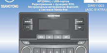
Руководство пользователя по автомагнитоле DWSY1003 для автомобиля SsangYong Stavic (2013г.в. – н.в.)
Руководство пользователя по автомагнитоле DWSY1003 для автомобиля SsangYong Stavic (2013г.в. – н.в.)
Скачать .pdf (2 мб)
-
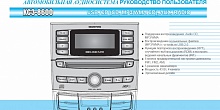
Руководство пользователя по автомагнитоле KC3-8600 для автомобиля SsangYong Actyon (2011г.в.-2013г.в.)
Руководство пользователя по автомагнитоле KC3-8600 для автомобиля SsangYong Actyon (2011г.в.-2013г.в.)
Скачать .pdf (5 мб)
-
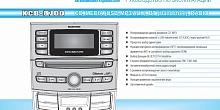
Руководство пользователя по автомагнитоле KCB-8700 для автомобиля SsangYong Actyon (2011г.в.-2013г.в.)
Руководство пользователя по автомагнитоле KCB-8700 для автомобиля SsangYong Actyon (2011г.в.-2013г.в.)
Скачать .pdf (4 мб)
-
Руководство пользователя по автомагнитоле для автомобиля SsangYong Actyon Sports (2012г.в.-н.в.)
Руководство пользователя по автомагнитоле для автомобиля SsangYong Actyon Sports (2012г.в.-н.в.)
Скачать .pdf (7 мб)
-
Руководство пользователя по автомагнитоле AGC-9145 для автомобиля Rexton (2013г.в.-н.в.)
Руководство пользователя по автомагнитоле AGC-9145 для автомобиля Rexton (2013г.в.-н.в.)
Скачать .pdf (3 мб)
-
Руководство пользователя по автомагнитоле MCD-8200 для автомобиля SsangYong Kyron (2007г.в.-н.в)
Руководство пользователя по автомагнитоле MCD-8200 для автомобиля SsangYong Kyron (2007г.в.-н.в)
Скачать .pdf (4 мб)
- Безопасность
- Мультимедиа
- Комфорт
- Транспортировка
- Все
-
Навигационная система SsangYong
-
Дорожный набор. Инструкция по эксплуатации
-
Механическая противоугонная система
-
Автосигнализация А61
-
Автосигнализация А91
-
Автосигнализация E61
-
Автосигнализации E91, E91GSM
-
Автосигнализация B64
-
Автосигнализации B94, В94GSM, B94GSM/GPS
-
Автосигнализации D94GSM, D94GSM/GPS
-
Поисковый модуль M15
-
Поисковый модуль M17
-
Поисковые модули M21-M31
-
GSM/GPS модуль
-
Интеллектуальные системы помощи при парковке
-
Велокрепление Quickball +
-
Бокс Vista черный 175х95х38 450 л.
-
McKinley лыж.крепление
-
Everest лыж.крепление
-
Грузовая платформа Excursion
-
Грузовая платформа Safari
-
Scott велокрепление
-
Крепление для лодок Sydney
-
Крепление для лодки Galactica
-
Дополнительная секция для Galactica
-
535 Zermatt крепеж для лыж
-
Крепеж для лодки Tahiti
-
Велокрепление на поперечины (прав.) Barracuda
-
Велокрепление на поперечины (лев.) Barracuda
-
Barracuda держатель велосипеда 2 в 1 (правый + левый)
-
Discovery велокрепление правый
-
Discovery велокрепление левый
-
Бокс Triton 350 сереб. черн. 162x88x41 380 л.
-
Бокс Triton 350 черн. черн. 162x88x41 380 л.
-
Бокс Triton 650 серый 224х94х43 620 л. 2-е откр.
-
Бокс Vista 320 135x85x38 320 л.
-
Бокс Vista 380 200х65х45 380 л.
-
Бокс Vista 450 175х95х38 450 л.
-
Бокс Vista 540 200х95х42 540 л.
-
Бокс Triton 450 черн. черн. 197x83x38 430 л., dual-opening, easemount
-
Бокс Triton 450 сереб. черн. 197x83x38 430 л., dual-opening, easemount
-
Багажник на рейлинги, сталь
-
Багажник на рейлинги, Alu


-
Сервисная книжка

-
Тест-драйв SsangYong Actyon Sports
Тест-драйв SsangYong Actyon Sports
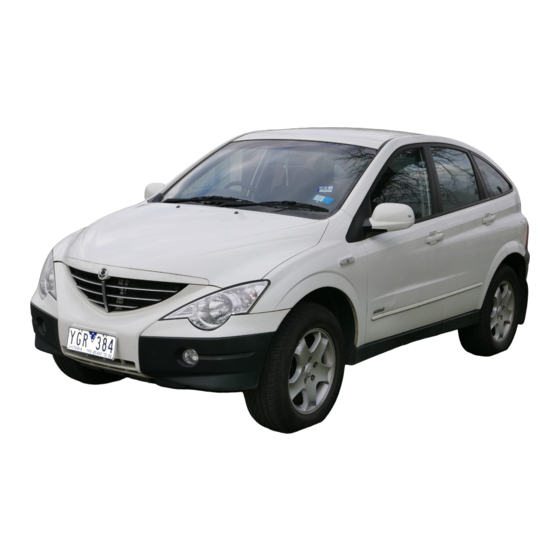
Кроссовер Actyon — принципиально новый автомобиль в линейке SsangYong, который призван стать первым шагом на пути к созданию нового модельного ряда.
Cмотреть видео

Главная
>
Сервис
>
Сервис
>
Руководства по эксплуатации
Руководства по эксплуатации
В этом разделе Вы можете скачать сервисную книжку и руководства по эксплуатации для автовладельцев SsangYong в формате pdf.

Руководство по эксплуатации SsangYong Actyon
Скачать (PDF)

Руководство по эксплуатации SsangYong Actyon
Скачать (PDF)
Руководство по эксплуатации SsangYong Kyron
Скачать (PDF)

Руководство по эксплуатации SsangYong Rexton
Скачать (PDF)

Руководство по эксплуатации SsangYong Rexton
Скачать (PDF)
Руководство по эксплуатации SsangYong Actyon Sports/ Actyon
Скачать (PDF)

Сервисная книжка
Скачать (PDF)
Сервис
- Сервис
- Руководства по эксплуатации
- Химчистка и полировка
- Запись на сервис
- Гарантийное обслуживание
- Кузовной ремонт
- Запчасти
- Аксессуары
Руководство на английском языке по техническому обслуживанию и ремонту + схемы электрооборудования автомобиля SsangYong Actyon второго поколения.
- Автор: —
- Издательство: SsangYong
- Год издания: 2012
- Страниц: —
- Формат: PDF
- Размер: 95,2 Mb
Сборник руководств на английском языке по техническому обслуживанию и ремонту + схемы электрооборудования автомобиля SsangYong Actyon первого поколения.
- Автор: —
- Издательство: SsangYong
- Год издания: 2006-2010
- Страниц: —
- Формат: PDF
- Размер: 1,3 Gb

Руководство по эксплуатации и техническому обслуживанию автомобилей SsangYong Actyon с 2013 года выпуска.
- Автор: —
- Издательство: Automechanic
- Год издания: —
- Страниц: 361
- Формат: —
- Размер: —
Руководство по техническому обслуживанию и ремонту автомобилей SsangYong New Actyon и SsangYong Korando C с 2010 года выпуска с дизельным двигателем объемом 2,0 л.
- Автор: —
- Издательство: Монолит
- Год издания: —
- Страниц: 347
- Формат: PDF
- Размер: 273,2 Mb

Руководство по техническому обслуживанию и ремонту автомобилей SsangYong New Actyon и SsangYong Korando C с 2010 года выпуска с дизельным двигателем объемом 2,0 л.
- Автор: —
- Издательство: Монолит
- Год издания: —
- Страниц: 356
- Формат: —
- Размер: —

Руководство по техническому обслуживанию и ремонту автомобилей SsangYong New Actyon и SsangYong Korando C с 2010 года выпуска с дизельным двигателем объемом 2,0 л.
- Автор: —
- Издательство: Монолит
- Год издания: —
- Страниц: 376
- Формат: —
- Размер: —
Руководство по техническому обслуживанию и ремонту + каталог расходных запчастей автомобиля SsangYong Actyon 2006-2010 годов выпуска с бензиновыми и дизельными двигателями.
- Автор: —
- Издательство: Легион-Автодата
- Год издания: 2015
- Страниц: 424
- Формат: —
- Размер: —
Руководство по техническому обслуживанию и ремонту + каталог расходных запчастей автомобилей SsangYong Actyon и SsangYong Korando с 2011 года выпуска с бензиновыми и дизельными двигателями.
- Автор: —
- Издательство: Легион-Автодата
- Год издания: 2015
- Страниц: 491
- Формат: —
- Размер: —

Руководство по техническому обслуживанию и ремонту автомобилей SsangYong Actyon и SsangYong Actyon Sports с 2006 года выпуска с бензиновыми и дизельными двигателями.
- Автор: —
- Издательство: Монолит
- Год издания: —
- Страниц: 352
- Формат: —
- Размер: —
Сборник руководств по эксплуатации и техническому обслуживанию автомобиля SsangYong Actyon второго поколения.
- Автор: —
- Издательство: SsangYong
- Год издания: —
- Страниц: —
- Формат: PDF
- Размер: 26,1 Mb
Сборник руководств по эксплуатации и техническому обслуживанию автомобиля SsangYong Actyon первого поколения.
- Автор: —
- Издательство: SsangYong
- Год издания: —
- Страниц: 304/347
- Формат: PDF
- Размер: 19,9 Mb

- Manuals
- Brands
- SSANGYONG Manuals
- Automobile
- Actyon 2008.01
- Manual
-
Contents
-
Table of Contents
-
Bookmarks
Quick Links
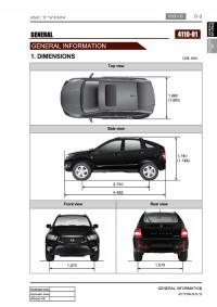
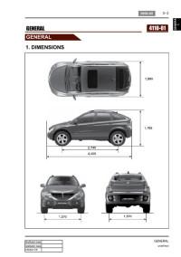
GENERAL
1. DIMENSIONS………………………………….
LUBRICANTS………………………………….
CONNECTOR………………………………….
LAYOUT…………………………………………
3
4
6
7
12
13
14
15
17
GENERAL
0000-00
GENERAL
Related Manuals for SSANGYONG Actyon 2008.01
Summary of Contents for SSANGYONG Actyon 2008.01
-
Page 1: Table Of Contents
GENERAL 0000-00 GENERAL GENERAL 1. DIMENSIONS……..2. SPECIFICATIONS……… 3. VEHICLE IDENTIFICATION….4. MAINTENANCE INTERVAL….5. RECOMMENDED FLUIDS AND LUBRICANTS……..6. JACK-UP POINTS (DOTTED CIRCLES). 7. PIN ARRANGEMENT OF DIAGNOSTIC CONNECTOR……..8. ELECTRIC COMPONENTS AND LAYOUT……….9. STANDARD BOLTS SPECIFICATIONS.
-
Page 2
0000-00 GENERAL ACTYON 2008.01… -
Page 3: Dimensions
0000-00 4110-01 GENERAL 1. DIMENSIONS GENERAL ACTYON 2008.01…
-
Page 4: Specifications
0000-00 2. SPECIFICATIONS GENERAL ACTYON 2008.01…
-
Page 5
0000-00 GENERAL ACTYON 2008.01… -
Page 6: Vehicle Identification
Engine Number (D20DT) Certification Label The engine number is stamped on the The certification label is located on lower area of cylinder block in the the driver’s door sill (B pillar). intake manifold side. GENERAL ACTYON 2008.01…
-
Page 7: Maintenance Interval
0000-00 4. MAINTENANCE INTERVAL 1) Diesel Engine * Use only approved Ssangyong genuine parts. Maintenance service and record retention are the owner’s responsibility. You should retain evidence that proper maintenance has been performed on your vehicle in accordance with the scheduled maintenance service chart.
-
Page 8
In heavy city traffic where the outside temperature regularly reaches 32°C (90°F) or higher, or In hilly or moutainous terrain. Severe Conditions in Air Conditioner Filter — Pollutant area or off-road driving, extended air conditioner or heater operation GENERAL ACTYON 2008.01… -
Page 9
0000-00 2) Gasoline Engine * Use only approved Ssangyong genuine parts. Maintenance service and record retention are the owner’s responsibility. You should retain evidence that proper maintenance has been performed on your vehicle in accordance with the scheduled maintenance service chart. -
Page 10
(5)* Inspect manual transmission fluid every 15,000 km (Inspect the leak of fluid at any time, occasionally), then change every 60,000 km (6)* Change automatic transmission fluid and every 60,000 km if the vehicle is mainly driven under severe conditions. (Inspect the leak of fluid at any time, occasionlly) GENERAL ACTYON 2008.01… -
Page 11
In heavy city traffic where the outside temperature regularly reaches 32°C (90°F) or higher, or In hilly or moutainous terrain. Severe Conditions in Air Conditioner Filter — Pollutant area or off-road driving, extended air conditioner or heater operation GENERAL ACTYON 2008.01… -
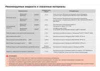
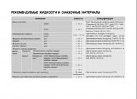
Page 12: Recommended Fluids And Lubricants
0-12 0000-00 5. RECOMMENDED FLUIDS AND LUBRICANTS Use only Ssangyong recommended fluids and lubricants. Do not mix any different types or brands of oils or fluids. This may cause damages. Keep the specified levels when adding or replacing the fluids.
-
Page 13: Jack-Up Points (Dotted Circles)
0-13 0000-00 6. JACK-UP POINTS GENERAL ACTYON 2008.01…
-
Page 14: Pin Arrangement Of Diagnostic Connector
0-14 0000-00 7. PIN ARRANGEMENT OF DIAGNOSTIC CONNECTOR It is installed under the instrument panel and consists of 16 pins 1) Functions of Terminal GENERAL ACTYON 2008.01…
-
Page 15: Electric Components And Layout
0-15 0000-00 8. ELECTRIC COMPONENTS AND LAYOUT 1) Wiring Harness Arrangement GENERAL ACTYON 2008.01…
-
Page 16
0-16 0000-00 2) Components Locator GENERAL ACTYON 2008.01… -
Page 17: Standard Bolts Specifications
0-17 0000-00 9. STANDARD BOLTS SPECIFICATIONS GENERAL ACTYON 2008.01…
-
Page 18
Determine extra proper tightening torque if tightens with washer or packing. If tightens bolts on the below materials, be sure to determine the proper torque. Aluminum alloy: Tighten to 80 % of above torque table. Plastics: Tighten to 20 % of above torque table. GENERAL ACTYON 2008.01… -
Page 19
ENGINE GENERAL 0000-00 ENGINE GENERAL GENERAL 1. ENGINE ASSEMBLY LAYOUT….2. ENGINE CONTROLS LAYOUT….3. ELECTRICAL COMPONENTS AND PREHEATING SYSTEM….4. INTAKE SYSTEM LAYOUT….5. EXHAUST SYSTEM LAYOUT….6. LUBRICATION SYSTEM LAYOUT..7. COOLING SYSTEM LAYOUT….8. FUEL SYSTEM LAYOUT……. 9. -
Page 21: Engine Assembly Layout
01-3 0000-00 0000-00 ENGINE GENERAL 1. ENGINE ASSEMBLY LAYOUT 1) LH SIDE VIEW 2) RH SIDE VIEW ENGINE GENERAL ACTYON 2008.01…
-
Page 22
01-4 0000-00 3) FRONT VIEW 4) FAN BELT ENGINE GENERAL ACTYON 2008.01… -
Page 23: Engine Controls Layout
Engine oil filler cap Vacuum pump PWM electric fan & fan shroud EGR valve Power steering oil reservoir Vacuum modulator Fuel filter & priming pump Brake fluid reservoir Battery ABS/ESP modulator Fuse box Air cleaner assembly Washer fluid reservoir ENGINE GENERAL ACTYON 2008.01…
-
Page 24
01-6 0000-00 2) Engine And Sensors Camshaft Position Sensor Injector Glow Plug Fuel Pressure Sensor Booster Pressure Sensor Common Rail (Common Rail) ENGINE GENERAL ACTYON 2008.01… -
Page 25
01-7 0000-00 HP Pump Knock Sensor (1 EA) & Crankshaft Vacuum Modulator Water Temperature Sensor Position Sensor Water temp. sensor Knock sensor ENGINE GENERAL ACTYON 2008.01… -
Page 26
01-8 0000-00 3) Engine Accessories Related to ECU IP Interior Fuse Box (Passenger Side) Installed Engine ECU main relay Hazard warning lamp VGT & EGR vacuum modulators, HFM HP pumpIMV Engine ECU Mounting Location ENGINE GENERAL ACTYON 2008.01… -
Page 27
Pump Filter Service Interval (Fuel Filter) Replace every 30,000 km (Draining water from fuel filter: Only whenever replacing the engine oil) Replace every 25,000 km General (Draining water from fuel filter: whenever replacing the engine oil) ENGINE GENERAL ACTYON 2008.01… -
Page 28: Electrical Components And Preheating System
01-10 0000-00 3. ELECTRICAL COMPONENTS AND PRE HEATING SYSTEM Battery Preheat Warning Lamp Glow Plug (Cluster) Engine compartment Alternator Starter motor fuse box PTC / FFH: 12V — 2.2kw 12V — 115A ENGINE GENERAL ACTYON 2008.01…
-
Page 29
No G5 for 4 cylinders (Without D20DT) IG1 power supply terminal Glow plug control signal (ECU113) Ground terminal Battery main wire Preheat completion transmit terminal : No use for vehicle without remote engine start K-line (ECU 34) ENGINE GENERAL ACTYON 2008.01… -
Page 30: Intake System Layout
01-12 0000-00 4. INTAKE SYSTEM Intake outlet hose Air cleaner Front air duct Terbocharger intercooler Supplying Compressed Air with Intake Manifold Turbocharger’s Operation To corresponding cylinders Coolant port Air cleaner Inter cooler Turbo charger From intercooler ENGINE GENERAL ACTYON 2008.01…
-
Page 31
01-13 0000-00 Recirculation of Exhaust Gas when Turbocharger Intercooler EGR Valve Operates EGR valve Intake com pressed air Exhaust gas HFM Sensor Plug-in sensor Temperature Pretension Air cleaner Turbo — charger — Sensor graph ENGINE GENERAL ACTYON 2008.01… -
Page 32: Exhaust System Layout
01-14 0000-00 5. EXHAUST SYSTEM EEGR Pipe Passage for recirculation of exhaust gas DOC (Diesel Catalytic Converter) Exhaust Manifold To turbo — To EGR charger pipe From cylinders ENGINE GENERAL ACTYON 2008.01…
-
Page 33
IP interior fuse duct hose valve that Engine ECU box (RH) opens/closes due to pressure differences (No. 95) No.63(7.5A) between the intake side and crankcase. ENGINE GENERAL ACTYON 2008.01… -
Page 34: Lubrication System Layout
01-16 0000-00 6. LUBRICATION SYSTEM Oil dipstick gauge Cylinder Head Cover Oil Pressure Warning Lamp (Cluster) Oil Pan and Baffle Plate (Integrated Type) Oil Strainer ENGINE GENERAL ACTYON 2008.01…
-
Page 35
Separated oil returns to oil pan via oil drain port and the gas will be burnt again after entering the combustion chamber through duct hose valve that opens/closes due to pressure differences between the intake side and crankcase. ENGINE GENERAL ACTYON 2008.01… -
Page 36: Cooling System Layout
Coolant inlet hose Return hose Coolant outlet hose PWM electric Radiator Coolant Port Water Pump & Pipe Thermostat (inside) Coolant — Cylinder outlet port Radiator block Reservoir (Coolant inlet hose) Radiator Assembly Cooling Fan and Fan Clutch ENGINE GENERAL ACTYON 2008.01…
-
Page 37
01-19 0000-00 Engine Oil Filter & Cooler Oil filter cap Oil cooler cooler filter Oil pressure switch ENGINE GENERAL ACTYON 2008.01… -
Page 38: Fuel System Layout
Fuel filter Connector HP Pump Fuel return port Fuel return port Fuel tempera — ture sensor Venturi IMV connector IMV valve High pres — sure fuel supply port Low pres — sure fuel supply port ENGINE GENERAL ACTYON 2008.01…
-
Page 39
01-21 0000-00 Cylinder Head Fuel return hose Fuel pipe Common rail High pressure fuel pipe Fuel rail pressure sensor ENGINE GENERAL ACTYON 2008.01… -
Page 40: Fuel Supply System
Furthermore, ECU uses signals from coolant temperature sensor and air temperature sensor, booster pressure sensor and barometric sensor as compensation signal to respond to injection starting, pilot injection set values, various operations and variables. ENGINE GENERAL ACTYON 2008.01…
-
Page 41: Cleanness
The core elements of fuel system has very high preciseness that is easily affected by dust or very small foreign material. Therefore, make sure to keep the preliminary works and job procedures in next pages. If not, lots of system problems and claims may arise. ENGINE GENERAL ACTYON 2008.01…
-
Page 42
At this point, thoroughly clean the related area in engine compartment. Clean the engine compartment before starting service works. Tool kit for Took kit for low Removal tool box and high pressure line pressure line cap kits ENGINE GENERAL ACTYON 2008.01… -
Page 43
If not, the injection point may be deviated from correct position, and it may cause engine disorder. Plug the disconnected parts with sealing caps, and remove the caps immediately before replacing the components. ENGINE GENERAL ACTYON 2008.01… -
Page 44
Priming pump filled pump. Check the installed components again and connect the negative battery cable. Start the engine and check the operating status. With SCAN-100, check if there are current faults and erase the history faults. ENGINE GENERAL ACTYON 2008.01… -
Page 45
Due to engine layout, a customer cannot easily drain water from fuel filter directly, so if a customer checks in to change engine oil, be sure to perform water drain from fuel filter. (See fuel system for details.) ENGINE GENERAL ACTYON 2008.01… -
Page 46: Maintenance And Repair
Using oils of any viscosity other than those viscosities recommended could result in engine damage. ▷ Cooling System Service Drain, flush and refill the system with new coolant. Refer to «Recommended Fluids And Lubricants» in this section. ENGINE GENERAL ACTYON 2008.01…
-
Page 47
Check the tires for abnormal wear or damage. To equalize wear and obtain maximum tire life, rotate the tires. If irregular or premature wear exists, check the wheel alignment and check for damaged wheels. While the tires and wheels are removed, inspect the brakes. Tire Rotation (Left-hand Drive Type) ENGINE GENERAL ACTYON 2008.01… -
Page 48: Guidelines For Service Work Safety
Notice means precautions on tool/device or part damages or personal injuries that can occur during service works. However, above references and cautions cannot be inclusive measures, so should have habits of taking concerns and cautions based on common senses. ENGINE GENERAL ACTYON 2008.01…
-
Page 49
LOCK position before work. · Be careful not to touch hot components like catalytic converter, muffler and exhaust pipe when the engine is running or just stopped. They may burn you badly. ENGINE GENERAL ACTYON 2008.01… -
Page 50
While removing engine, drain engine oil, coolant and fuel in fuel system to prevent leakage. During service work of removal/installation, be sure to check each connected portions to engine not to make interference. ENGINE GENERAL ACTYON 2008.01… -
Page 51
When replacing electrical equipment, use the same genuine part and be sure to check whether ground or connecting portions are correctly connected during installation. If ground or connecting portion is loosened, there can be vehicle fire or personal injury. ENGINE GENERAL ACTYON 2008.01… -
Page 52: During Service Work For Inspection
Brake fluid and anti-freeze can damage painted surface of body. So carefully handle them during service work. Use recommended and specified tools to increase efficiency of service work. Use only genuine spare parts. ENGINE GENERAL ACTYON 2008.01…
-
Page 53
(Refer to cleanness.) If remove high pressure fuel supply pipe between HP pump and fuel rail and high pressure fuel pipe between fuel rail and each injector, be sure to replace them with new. ENGINE GENERAL ACTYON 2008.01… -
Page 54: During Service Work For Electric Devices
If lift up the vehicle with safety jack and stand, should be more careful during works. Never be under the vehicle if supported with only jack. If have to be under the vehicle, · be sure to use safety block. Use wheel block in front and rear of every wheel. · ENGINE GENERAL ACTYON 2008.01…
-
Page 55: Owner Inspections And Services
▶ Headlamp Aim Take note of the light pattern occasionally. Adjust the headlights if the beams seem improperly aimed. ENGINE GENERAL ACTYON 2008.01…
-
Page 56
Periodically inspect the surface beneath the vehicle for water, oil, fuel or other fluids, after the vehicle has been parked for a while. Water dripping from the air conditioning system after use is normal. If you notice fuel leaks or fumes, find the cause and correct it at once. ENGINE GENERAL ACTYON 2008.01… -
Page 57
▶ Hood Latch Operation When opening the hood, note the operation of the secondary latch. It should keep the hood from opening all the way when the primary latch is released. The hood must close firmly. ENGINE GENERAL ACTYON 2008.01… -
Page 58
Inspect the hoses. Replace the cracked, swollen, or deteriorated hoses. Tighten the clamps. Clean the outside of the radiator and the air conditioning condenser. Wash the filler cap and the neck. Pressure test the cooling system and the cap in order to help ensure proper operation. ENGINE GENERAL ACTYON 2008.01… -
Page 59: Standard Bolts Specifications
01-41 0000-00 16. STANDARD BOLTS SPECIFICATIONS ENGINE GENERAL ACTYON 2008.01…
-
Page 60
Determine extra proper tightening torque if tightens with washer or packing. If tightens bolts on the below materials, be sure to determine the proper torque. Aluminum alloy: Tighten to 80 % of above torque table. Plastics: Tighten to 20 % of above torque table. ENGINE GENERAL ACTYON 2008.01… -
Page 61
It satisfies the strict emission regulation and provides improved output and maximum torque. Oil separator Coolant (PCV valve) reservoir Engine oil Vacuum dipstick pump Air cleaner assembly Engine oil filler cap VGT Turbo sensor charger Engine ENGINE ASSEMBLY ACTYON 2008.01… -
Page 62
02-3 1212-01 Vacuum modulator ABS/ESP Brake fluid modulator EGR valve reservoir Battery Fuel filter & priming pump Washer fluid reservoir Power steering oil PWM electric reservoir fan & fan shroud ENGINE ASSEMBLY ACTYON 2008.01… -
Page 63
Oil separator (with PCV) VGT Turbo charger EGR pipe Water pump pulley Alternator Crankshaft pulley Oil pan Auto tensioner Air conditioner compressor Auto tensioner pulley Power steering pump pulley Power steering pump EGR valve Idle pulley Viscos clutch pulley ENGINE ASSEMBLY ACTYON 2008.01… -
Page 64
Fuel pressure sensor Water outlet port EGR valve Oil filler Booster pressure sensor Common rail (25 ± 2.5 Nm) Vacuum pump (10 ± 1.0 Nm) Glow plug (15 ± 3 Nm) Cylinder head cover VGT Turbo charger ENGINE ASSEMBLY ACTYON 2008.01… -
Page 65
Air conditioner compressor Engine mounting bracket Vacuum modulator for VGT turbocharger actuator Flywheel Crank position sensor Gap: 0.7 ~ 1.5 mm Vacuum modulator for EGR valve Oil filter & oil cooler Vacuum pump Booster pressure sensor Intake manifold ENGINE ASSEMBLY ACTYON 2008.01… -
Page 66
02-7 1212-01 Left Side View Cylinder head jack valve screw VGT Turbo charger assembly Cylinder block assembly Engine mounting bracket Oil pan Alternator Water pump EGR pipe Oil dipstick gauge Oil separator (with PCV) ENGINE ASSEMBLY ACTYON 2008.01… -
Page 67
02-8 1212-01 2. SPECIFICATIONS AND PERFORMANCE CURVE 1) Specifications ENGINE ASSEMBLY ACTYON 2008.01… -
Page 68
02-9 1212-01 2) Engine Performance Curve (1) Output and Torque (2) Oil Temperature/Pressure and Boost Pressure ENGINE ASSEMBLY ACTYON 2008.01… -
Page 69
02-10 1212-01 3. TIGHTENING TORQUE ENGINE ASSEMBLY ACTYON 2008.01… -
Page 70
02-11 1212-01 ENGINE ASSEMBLY ACTYON 2008.01… -
Page 71
02-12 1212-01 ENGINE ASSEMBLY ACTYON 2008.01… -
Page 72
— Initial cleaning: 5,000 km, Clean or change every 10,000 km as required. However, change every 30,000 km. Service Interval — If the vehicle is operated under severe condition (short distance driving, extensive ldling or driving in dusty condition): More frequent maintenance is required. ENGINE INTAKE SYSTEM ACTYON 2008.01… -
Page 73
1. Plug-in sensor 2. Cylinder housing 3. Protection grid Plug-in sensor 4. Hybrid cover 5. Measuring duct cover 6. Housing 7. Hybrid 8. Sensor 9. Mounting plate Temperature 10. O-ring Protection grid sensor 11. Temperature sensor ENGINE INTAKE SYSTEM ACTYON 2008.01… -
Page 74
Turbocharger Intercooler The charging efficiency may be lowered or the knocking may happen as the intake air is heated and the density of air is lowered. The intercooler is the device which cools the supercharged air. ENGINE INTAKE SYSTEM ACTYON 2008.01… -
Page 75
04-6 2313-01 2) Layout ENGINE INTAKE SYSTEM ACTYON 2008.01… -
Page 76
The inlet port and coolant outlet port is integrated together. Therefore, be careful not to let the residual coolant in the manifold enter the inlet port when removing the intake manifold. Also, replace the gasket with a new one and tighten it to the specified torque (25 ± 2.5 Nm). ENGINE INTAKE SYSTEM ACTYON 2008.01… -
Page 77
Intake air Intake air Exhaust gas 1. EGR pipe (RH) 5. Exhaust gas 2. EGR pipe (center) 6. EGR pipe (LH) 3. Coolant emission port 7. Vacuum modulator to the EGR valve 4. Intake air (intercooler) ENGINE INTAKE SYSTEM ACTYON 2008.01… -
Page 78
Thus, more air is entered the cylinder than the engine only with the turbocharger to give more power. Intercooler For removal and installation procedures, refer to the «Cooling system» section in DI engine service manual. ENGINE INTAKE SYSTEM ACTYON 2008.01… -
Page 79
04-10 2313-01 2. AIR FLOWS 1) Work Flow of Intake System ENGINE INTAKE SYSTEM ACTYON 2008.01… -
Page 80
The DI engine ECU receives feedback signal of change in amount of air being passed through the HFM sensor according to the opening amount of the EGR valve. ENGINE EXHAUST SYSTEM ACTYON 2008.01… -
Page 81
Therefore, disregarding the modulator for the EGR valve in DI engine, one must keep in mind that the other modulator is used to control the booster pressure valve in turbo charger. ENGINE EXHAUST SYSTEM ACTYON 2008.01… -
Page 82
EGR Valve and Installation Location Intake air Intake (intercooler) manifold Intake Intake manifold manifold EGR pipe EGR pipe (LH) Exhaust Manifold Exhaust manifold To turbo- To EGR EGR pipe (RH) charger valve Diesel catalytic converter → Muffler ENGINE EXHAUST SYSTEM ACTYON 2008.01… -
Page 83
05-6 1913-01 2) Exhaust Gas Flows ENGINE EXHAUST SYSTEM ACTYON 2008.01… -
Page 84
When operating in dusty, sandy and salty areas In hilly or moutainous terrain When doing frequent trailer towing 2. OIL PRESSURE SWITCH Operating temperature: -40 ~ 140°C Operating pressure: 0.3 ~ 0.55 bar Permissible pressure: 10 bar LUBRICATION SYSTEM ACTYON 2008.01… -
Page 85
Blow-by gas again after entering the combustion chamber (air duct hose) through air duct hose via PCV valve that Inlet port opens/closes due to pressure differences between the intake side and crankcase. Oil (oil gauge pipe) LUBRICATION SYSTEM ACTYON 2008.01… -
Page 86
06-5 1533-01 Oil pressure Warning Lamp Cylinder Head Cover (Cluster) Oil Pan and Baffle Plate Oil Strainer Oil Filter & Oil Cooler (Integrated Type) cooler filter LUBRICATION SYSTEM ACTYON 2008.01… -
Page 87
Main oil gallery: φ 16 Hole to cylinder head: φ 9 Main bearing hole: φ 7 Chain and injection pump: φ 7 Return hole: φ 14 Chain nozzle: φ 1 HP pump bearing: φ 6 Cylinder Block LUBRICATION SYSTEM ACTYON 2008.01… -
Page 88
2. LUBRICATION DIAGRAM Opening pressure of by-pass valve in oil filter: 3 ± 0.4 bar To prevent instant oil shortage after stopping the engine, the return check valve is installed in oil supply line of cylinder head LUBRICATION SYSTEM ACTYON 2008.01… -
Page 89
07-3 2112-01 9210-05 ENGINE COOLING SYSTEM 1. ENGINE COOLING SPECIFICATIONS COOLING SYSTEM ACTYON 2008.01… -
Page 90
07-4 2112-01 1. COMPONENTS ENGINE COOLING Coolant Reservoir Water Pump Cooling Fan and Coolant Radiator Assembly Fan Clutch Temperature Sensor COOLING SYSTEM ACTYON 2008.01… -
Page 91
Cylinder block side · Block #5 → Oil cooler → Heater → Heater water pump inlet pipe → Water pump Cylinder head side · Cylinder head → Coolant outlet port (intake #1) → Radiator → Water pump COOLING SYSTEM ACTYON 2008.01… -
Page 92
It prevents cooling efficiency from decreasing due to coolant separation between · cylinder #4 and #5. In OM 600 engine, the cooling fan is installed with water pump, however, in case of D27DT engine, it is connected to water pump with an additional pulley. COOLING SYSTEM ACTYON 2008.01… -
Page 93
08-3 1451-01 1461-01 ENGINE ELECTRICAL SYSTEM 1.SPECIFICATIONS OF ENGINE ELECTRIC ENGINE ELECTRIC DEVICES ACTYON 2008.01… -
Page 94
08-4 1451-01 1. COMPONENTS OF ELECTRIC IN ENGINE Fuel Pressure Camshaft Position Coolant Temperature Fuel Temperature Sensor Sensor Sensor Sensor Booster Pressure Oil Pressure Switch Crankshaft Position Knock Sensor Sensor Sensor (1 EA) ENGINE ELECTRIC DEVICES ACTYON 2008.01… -
Page 95
08-5 1451-01 2. COMPONENTS OF ELECTRIC DEVICES IN ENGIN Alternator Glow Plug Capacity PTC equipped vehicle : 12V — 140A FFH equipped vehicle : 12V — 115A Air Conditioner Compressor Starter ENGINE ELECTRIC DEVICES ACTYON 2008.01… -
Page 96
08-6 1451-01 3. CIRCUIT DIAGRAM OF PREHEATING SYSTEM 1) Preheating ENGINE ELECTRIC DEVICES ACTYON 2008.01… -
Page 97
08-7 1451-01 4. CIRCUIT DIAGRAM OF STARTING AND ALTERNATOR 1) Starting & Charging ENGINE ELECTRIC DEVICES ACTYON 2008.01… -
Page 98
Water Pump and Pipe Coolant Port Thermostat (inside) Cylinder block Coolant outlet Radiator port Reservior (coolant inlet hose) Engine Oil Filter and Cooler Oil Filter cap Oil cooler Oil cooler Oil filter Oil pressure switch ENGINE CONTROL SYSTEM ACTYON 2008.01… -
Page 99
09-4 1491-01 2. TOP VIEW Fuel Pressure Sensor Booster Pressure Sensor Injectors (4 EA) Glow Plugs (4 EA) ENGINE CONTROL SYSTEM ACTYON 2008.01… -
Page 100
09-5 1491-01 3. SIDE VIEW Coolant Temperature Knock Sensors (1 EA) Sensor Fuel Temperature Sensor Fuel Pressure Crankshaft Position Regulating Valve Sensor ENGINE CONTROL SYSTEM ACTYON 2008.01… -
Page 101
(Water warning light, glow Accelerator sensor plug Vehicle speed sensor indicator light, engine warning Switch input signal light) (IG, brake, clutch, A/C signal, Preheater (auxiliary heater) A/C compressor) K — line CAN communication Self-diagnosis ENGINE CONTROL SYSTEM ACTYON 2008.01… -
Page 102
Driving mode control If the vehicle runs normally, fuel injection volume will be calculated by accelerator pedal travel and engine rpm and the drive map will be used to match the drivers inputs with optimum engine power. ENGINE CONTROL SYSTEM ACTYON 2008.01… -
Page 103
If the pressure is lower than the demand, current is reduced so that the fuel sent to the high pressure pump is increased. If the pressure is higher than the demand, current is increased so that the fuel sent to the high pressure pump is reduced. ENGINE CONTROL SYSTEM ACTYON 2008.01… -
Page 104
To do this, special mapping is used to determine the injection timing advance as a function of the engine speed and of the water temperature. This requirement only concerns the starting phase, since once the engine has started the system must re-use the mapping and the corrections described previously. ENGINE CONTROL SYSTEM ACTYON 2008.01… -
Page 105
This correction is used to adapt the pilot injection timing as a function of the atmospheric pressure and therefore the altitude. During the starting phase, the pilot injection timing is determined as a function of the engine speed and of the coolant temperature. ENGINE CONTROL SYSTEM ACTYON 2008.01… -
Page 106
This strategy leads to a fuel correction which is added to the total fuel of each cylinder. The correction is determined before each injection as a function of the instantaneous engine speed. ENGINE CONTROL SYSTEM ACTYON 2008.01… -
Page 107
A mapping determines the minimum fuel which can control an injector as a function of the rail pressure. As soon as the main fuel falls below this value, the fuel demand changes to 0 because in any case the injector is not capable of injecting the quantity demand. ENGINE CONTROL SYSTEM ACTYON 2008.01… -
Page 108
The system compares the driver demand with this limit and chooses the smaller of the 2 values. The driver demand is then corrected according to the coolant temperature. This correction is added to the driver demand. ENGINE CONTROL SYSTEM ACTYON 2008.01… -
Page 109
A correction depending on the air temperature and the atmospheric pressure is made in order to increase the supercharge flow during cold starts. It is possible to alter the supercharge flow value by adding a flow offset with the aid of the diagnostic tool. ENGINE CONTROL SYSTEM ACTYON 2008.01… -
Page 110
The cylinder balancing strategy also allows the detection of an injector which has stuck closed. The difference in instantaneous speed between 2 successive injections then exceeds a predefined threshold. In this case, a fault is signaled by the system. ENGINE CONTROL SYSTEM ACTYON 2008.01… -
Page 111
The first MDP value is provided by the C2I. Each resetting then allows the closed loop of the MDP to be updated according to the deviation of the injector. ENGINE CONTROL SYSTEM ACTYON 2008.01… -
Page 112
The recovery modes associated with this fault consist of inhibition of the pilot injection and discharge through the injectors. ENGINE CONTROL SYSTEM ACTYON 2008.01… -
Page 113
The method consists in correcting the pulse that is applied to the injector with an offset that depends on the initial hydraulic map of the injector. So, the pulse should be corrected according to characteristics of each injector. ENGINE CONTROL SYSTEM ACTYON 2008.01… -
Page 114
When ECU is replaced, C2I code of every injector should be input. If not, cannot accelerate the vehicle even when the accelerator pedal is depressed. C2I Number value (16 digits) For coding of C2I, refer to «Diagnosis» section ※ ENGINE CONTROL SYSTEM ACTYON 2008.01… -
Page 115
1 ~ 2 mm/str, so precise control of the injector can be difficult if it gets old. So there needs MDP learning to control the very small volume precisely through learning according to getting older injectors. 1) Learning Conditions 2) Trouble Codes ENGINE CONTROL SYSTEM ACTYON 2008.01… -
Page 116
SPECIAL SERVICE TOOLS 0000-00 SPECIAL SERVICE TOOLS GENERAL 1. ENGINE ASSEMBLY……2. ENGINE HOUSING ASSEMBLY SPECIAL TOOLS ANDEQUIPMENT..3. ENGINE INTAKE …….. -
Page 117
10-2 0000-00 SPECIAL SERVICE TOOLS ACTYON 2008.01… -
Page 118
1. ENGINE ASSEMBLY Injector Puller Glow Plug Wrench Sealing Caps Fuel Pipe Wrench Y99220072B Y99220132B 665 995 5844 Injector Copper Washer Puller Y99220022B Valve Pulley Engine Lock Remover/Installer Lock/Wrench 602 589 00 40 00 Y99220082B Y99220052B SPECIAL SERVICE TOOLS ACTYON 2008.01… -
Page 119
10-4 0000-00 Glow Plug Socket Removal/Installation Removal/Installation Head Bolt Wrench Socket for High Pressure Device for HP Pump Pipe SPECIAL SERVICE TOOLS ACTYON 2008.01… -
Page 120
0000-00 2. ENGINE HOUSING ASSEMBLY SPECIAL TOOLS AND EQUIPMENT Name and Part Number Application Y99220092B Compression pressure measuring adapter and gauge Y99220082B Supporting bar and lever Y99220162B Guide pin extractor Y99220112B Intake manifold guide pin SPECIAL SERVICE TOOLS ACTYON 2008.01… -
Page 121
10-6 0000-00 Name and Part Number Application Y99220152B HLA remover Y99220142B Stem seal installer SPECIAL SERVICE TOOLS ACTYON 2008.01… -
Page 122
10-7 0000-00 3. ENGINE INTAKE Name and Part Number Application Y99220112B Installation of intake manifold Intake manifold guide pin SPECIAL SERVICE TOOLS ACTYON 2008.01… -
Page 124
The cruise control system is a supplementary system, which helps the driver to drive the vehicle at a desired speed without using the accelerator pedal under the traffic condition where the vehicle-to-vehicle distance meets the legal requirement. CRUISE CONTROL SYSTEM ACTYON 2008.01… -
Page 125
Use the cruise control system only when driving on motorways or highways. Do not use the cruise control system where the road conditions are as follows: — When there is strong wind or cross wind. — Heavy traffic. — Slippery roads or steep decline. CRUISE CONTROL SYSTEM ACTYON 2008.01… -
Page 126
11-5 8510-23 2. CIRCUIT DIAGRAM 1) Configuration CRUISE CONTROL SYSTEM ACTYON 2008.01… -
Page 127
Refer to the following pages for details of operation. Never use the cruise control system until you get used to it. Improper use or not fully aware of this function could result in collision and/or personal injuries. CRUISE CONTROL SYSTEM ACTYON 2008.01… -
Page 128
(0.81 mph). For example, if you want to increase the speed 13 km/h (81 mph) more than the previous set speed, tap up the switch lever to ACCEL side ten times without using the accelerator pedal. CRUISE CONTROL SYSTEM ACTYON 2008.01… -
Page 129
(0.62 mph). For example, if you want to decrease the speed 10 km/h (62 mph) lower than the previous set speed, tap down the switch lever to DECEL side ten times without using the brake pedal. CRUISE CONTROL SYSTEM ACTYON 2008.01… -
Page 130
But the driver should know the previous set speed to react to the changed vehicle speed properly. If the vehicle speed increases abruptly, depress the brake pedal to adjust the vehicle speed properly. CRUISE CONTROL SYSTEM ACTYON 2008.01… -
Page 131
Ensure that the braking distance is maintained and use the brake pedal if needed. CRUISE CONTROL SYSTEM ACTYON 2008.01… -
Page 132
1. MAJOR COMPONENTS IN ENGINE AND ENGINE COMPARTMENT The electronically controlled advanced D20DT engine that has high pressure fuel system has been introduced to this vehicle. It satisfies the strict emission regulation and provides improved output and maximum torque. D20DT (EURO) D20DT ENGINE ASSEMBLY ACTYON 2008.01… -
Page 133
01-4 1114-00 1) Engine Assembly Structure Front View Touch idler equipped (for A/T) Top View ENGINE ASSEMBLY ACTYON 2008.01… -
Page 134
01-5 1114-00 Right Side View Left Side View ENGINE ASSEMBLY ACTYON 2008.01… -
Page 135
01-6 1114-00 2. SPECIFICATIONS AND PERFORMANCE CURVE 1) Specifications ENGINE ASSEMBLY ACTYON 2008.01… -
Page 136
01-7 1114-00 2) Engine Performance Curve (1) Output and Torque General (2) Oil Temperature/Pressure and Boost Pressure General ENGINE ASSEMBLY ACTYON 2008.01… -
Page 137
01-8 1114-00 3. TIGHTENING TORQUE ENGINE ASSEMBLY ACTYON 2008.01… -
Page 138
01-9 1114-00 ENGINE ASSEMBLY ACTYON 2008.01… -
Page 139
01-10 1114-00 ENGINE ASSEMBLY ACTYON 2008.01… -
Page 140
Installation order (Based on the number in the picture) 10 → 9 → 8 → 7 → 6 → 5 → 4 → 3 → 2 → 1 → 14 → 13 → 12 → 11 (Reverse order of removal) ENGINE ASSEMBLY ACTYON 2008.01… -
Page 141
4. MAJOR CHANGES IN D20DT (EURO IV) ENGINE (COMPARED TO D20DT) 1) Engine Assembly D20DT (EURO 4) Engine D20DT Engine Front Side View Touch idler equipped (for A/T) Top Side View Right Side View Left Side View ENGINE ASSEMBLY ACTYON 2008.01… -
Page 142
* E-EGR valve: Electric controlled E-EGR valve EGR valve ECU controls the EGR valve directly without any media. It provide more precise EGR control by transmitting the electric signal of EGR valve operating position. ENGINE ASSEMBLY ACTYON 2008.01… -
Page 143
* Reason of changes EGR system layout To satisfy the emission E-EGR valve Throttle regulation, E-EGR valve body cooler adopted. And the layout also has a great difference from D27DT. EGR cooler EGR center pipe EGR valve ENGINE ASSEMBLY ACTYON 2008.01… -
Page 144
Also, mounting location of booster pressure sensor is changed. Water pump For D20DT (EURO4) engine: Additional connecting port for EGR cooler hose Coolant outlet port For D20DT (EURO4) engine: Additional port for coolant of EGR cooler ENGINE ASSEMBLY ACTYON 2008.01… -
Page 145
(It is also installed on the connection of the high pressure fuel supply line of the HP pump.) ENGINE FUEL SYSTEM ACTYON 2008.01… -
Page 146
Also, the engine ECU, HFM sensor and EGR system are changed to control the fuel injection volume and engine more precisely. Fuel high pressure pipe (HP pump → Common rail) ENGINE FUEL SYSTEM ACTYON 2008.01… -
Page 148
(7) Common Rail (Orifice for Preventing Fuel Pulsation Added) Orifice Orifice for HP pump fuel outlet Fuel Supply Rail (Increase in I.D) Fuel pipe Common rail Fuel rail pressure High pressure sensor fuel pipe ENGINE FUEL SYSTEM ACTYON 2008.01… -
Page 149
HP pump Fuel tank HP pump Fuel tank HP Pump Fuel temperature Fuel return Fuel return port sensor port IMV valve Venturi High pressure Low pressure fuel supply port fuel supply port (orifice included) connector ENGINE FUEL SYSTEM ACTYON 2008.01… -
Page 150
02-8 1881-00 2. FUEL FLOW OF D20DT (EURO 4) ENGINE ENGINE FUEL SYSTEM ACTYON 2008.01… -
Page 151
Also, the improved HFM sensor (from HFM5.0 to HFM6.0) has been installed to control the intake air precisely so that the NOx in the exhaust gas can be decreased. ENGINE INTAKE SYSTEM ACTYON 2008.01… -
Page 152
03-4 2321-01 2. INTAKE SYSTEM LAYOUT Uncompressed air Compressed air VGT Turbo Chargera Air cleaner Ambient air HFM Sensor (ver. 6.0) Temperature sensor Turbo coeaner charger Pretension graph ENGINE INTAKE SYSTEM ACTYON 2008.01… -
Page 153
To corresponding Coolant Supply power cylinders Ground port Output voltage Compress ed air EGR gas Throttle body Normal: flap open Engine stopped: flap closed Intake duct Intake duct Intercooler Intake manifold Turbo charger (Throttle body) ENGINE INTAKE SYSTEM ACTYON 2008.01… -
Page 154
Intake manifold Turbocharger intercooler (Intake compressed air) EGR gas (From EGR cooler) Exhaust manifold Throttle bod Turbocharger EGR pipe EGR pipe E-EGR valve EGR cooler Coolant E-EGR valve To EGR cooler Intake manifold Exhaust manifold ENGINE EXHAUST SYSTEM ACTYON 2008.01… -
Page 155
Separated oil returns to oil pan via oil drain port and the gas will be burnt again after entering the combustion chamber through air duct hose via PCV valve that opens/closes due to pressure differences between the intake side and crankcase. ENGINE LUBRICATION SYSTEM ACTYON 2008.01… -
Page 156
If too much oil or particulate material is accumulated, check the followings: 1. Engine oil level 2. EGR valve (exhaust gas leak and operating condition) 3. Turbocharger (oil/gas leak and operating condition) 4. PCV oil separator (installation condition and leak) 5. PCV oil separator (some functions) ENGINE LUBRICATION SYSTEM ACTYON 2008.01… -
Page 157
ENGINE COOLING SYSTEM 2112-00/1520-00 ENGINE COOLING SYSTEM COOLING SYSTEM 1. COMPARISON IN COOLING SYSTEM FOR EACH ENGINE……. WATER PUMP 1. OVERVIEW………. -
Page 158
06-2 0000-00 ENGINE COOLING SYSTEM ACTYON 2008.01… -
Page 159
For the D20DT (EURO4) engine, the cooling system is equipped with E-EGR cooler and the water pump which its capacity is improved according to the additional coolant line in the cylinder block. 1) Cooling System for Engine ENGINE COOLING SYSTEM ACTYON 2008.01… -
Page 160
The capacity of water pump has been increased due to the EGR cooler, increased engine power and additional coolant port in the cylinder block. For D20DT (EURO4) engine For D20DT engine Port to EGR cooler ENGINE COOLING SYSTEM ACTYON 2008.01… -
Page 161
06-5 0000-00 1) Structure of Water Pump for D20DT Engine ENGINE COOLING SYSTEM ACTYON 2008.01… -
Page 163
The glow control relay (K-line communication with engine ECU) is deleted. The unit communicates via CAN communication with engine ECU. Also, the number of pins is increased as glow plug’s performance has been improved (1000 C increase in approx. 2 ° seconds). ENGINE ELECTRICAL SYSTEM ACTYON 2008.01… -
Page 164
07-4 1491-01 2. D20DT (EURO4) ENGINE’S ECU CIRCUIT ENGINE ELECTRICAL SYSTEM ACTYON 2008.01… -
Page 165
SPECIAL SERVICE TOOLS 0000-00 SPECIAL SERVICE TOOLS GENERAL 1. LOCATION OF ENGINE AND MAJOR SPECIAL SERVICE TOOLS…. -
Page 166
08-2 0000-00 SPECIAL SERVICE TOOLS ACTYON 2008.01… -
Page 167
1. LOCATION OF ENGINE AND MAJOR SPECIAL SERVICE TOOLS Injector copper washer Injector Puller Glow Plug Socket Puller Sealing Caps (Fuel line) Removal/Installation Device Removal/Installation Socket for Head Bolt Wrench for HP Pump High Pressure Pipe SPECIAL SERVICE TOOLS ACTYON 2008.01… -
Page 169
The cruise control system is a supplementary system, which helps the driver to drive the vehicle at a desired speed without using the accelerator pedal under the traffic condition where the vehicle-to-vehicle distance meets the legal requirement. CRUISE CONTROL SYSTEM ACTYON 2008.01… -
Page 170
Use the cruise control system only when driving on motorways or highways. Do not use the cruise control system where the road conditions are as follows: — When there is strong wind or cross wind. — Heavy traffic. — Slippery roads or steep decline. CRUISE CONTROL SYSTEM ACTYON 2008.01… -
Page 171
09-5 8510-23 2. CIRCUIT DIAGRAM 1) Configuration CRUISE CONTROL SYSTEM ACTYON 2008.01… -
Page 172
Refer to the following pages for details of operation. Never use the cruise control system until you get used to it. Improper use or not fully aware of this function could result in collision and/or personal injuries. CRUISE CONTROL SYSTEM ACTYON 2008.01… -
Page 173
(0.81 mph). For example, if you want to increase the speed 13 km/h (81 mph) more than the previous set speed, tap up the switch lever to ACCEL side ten times without using the accelerator pedal. CRUISE CONTROL SYSTEM ACTYON 2008.01… -
Page 174
(0.62 mph). For example, if you want to decrease the speed 10 km/h (62 mph) lower than the previous set speed, tap down the switch lever to DECEL side ten times without using the brake pedal. CRUISE CONTROL SYSTEM ACTYON 2008.01… -
Page 175
But the driver should know the previous set speed to react to the changed vehicle speed properly. If the vehicle speed increases abruptly, depress the brake pedal to adjust the vehicle speed properly. CRUISE CONTROL SYSTEM ACTYON 2008.01… -
Page 176
Ensure that the braking distance is maintained and use the brake pedal if needed. CRUISE CONTROL SYSTEM ACTYON 2008.01… -
Page 177
Battery cables should be disconnected before any major work is performed on the engine. Failure to disconnect cables may result in damage to wire harness or other electrical parts. ENGINE ASSEMBLY ACTYON 2008.01… -
Page 178
Any time the air cleaner is removed, the intake opening should be covered. This will protect against accidental entrance of foreign material, which could follow the intake passage into the cylinder and cause extensive damage when the engine is started. ENGINE ASSEMBLY ACTYON 2008.01… -
Page 179
01-5 1113-01 2. G23D ENGINE ASSEMBLY Front View Rear View ENGINE ASSEMBLY ACTYON 2008.01… -
Page 180
01-6 1113-01 LH Side View RH Side View ENGINE ASSEMBLY ACTYON 2008.01… -
Page 181
01-7 1113-01 3. G23D ENGINE STRUCTURE Front View Side View ENGINE ASSEMBLY ACTYON 2008.01… -
Page 182
Side View FUNCTION FUNCTION Camshaft Adjuster Oil Pump Drive Chain Oil Filler Cap Oil Strainer Engine Hanger Bracket Oil Pump Cooling Fan and Viscous Clutch Ring Gear and Flywheel of Drive Plate Oil Filter Piston Timing Chain ENGINE ASSEMBLY ACTYON 2008.01… -
Page 183
Apply an aerosol-type powder (such as foot powder) to the suspected area. Operate the vehicle under normal operating conditoins. Visually inspect the suspected component. You should be able to trace the leak path over the white powder surface to the source. ENGINE ASSEMBLY ACTYON 2008.01… -
Page 184
The seal bore is damaged (scratched, burred or nicked). The seal is damaged or worn. Improper installation is evident. There are cracks in the components. The shaft surface is scratched, nicked or damaged. A loose or worn bearing is causing excess seal wear. ENGINE ASSEMBLY ACTYON 2008.01… -
Page 185
Measure the compression pressure of the other cylinders in the same way. If measured value is not within the specifications, perform the cylinder pressure leakage test. Discharge the combustion residues in the cylinders before testing the compression pressure. Apply the parking brake before cranking the engine. ENGINE ASSEMBLY ACTYON 2008.01… -
Page 186
Max. 10 % At Piston and Piston Ring Max. 20 % Cylinder Number ▶ 1, 4 OT (TDC) 2, 3 UT (BDC 180 °) ▶ Cylinder Number Cylinder Pressure Bosch, EFAW210A Sun, CLT 228 Leakage Tester ENGINE ASSEMBLY ACTYON 2008.01… -
Page 187
Measure the leakage volume in the completely opening condition of throttle valve by pulling the acceleration cable. Perform the pressure test according to the firing order. Firing Order: 1 — 3 — 4 — 2 Compare the leakage pressure with the specifications. ENGINE ASSEMBLY ACTYON 2008.01… -
Page 188
01-14 1113-01 5. GENERAL DIAGNOSIS ENGINE ASSEMBLY ACTYON 2008.01… -
Page 189
01-15 1113-01 ▶ General Diagnosis (Cont’d) ENGINE ASSEMBLY ACTYON 2008.01… -
Page 190
01-16 1113-01 ▶ General Diagnosis (Cont’d) ENGINE ASSEMBLY ACTYON 2008.01… -
Page 191
01-17 1113-01 ▶ General Diagnosis (Cont’d) ENGINE ASSEMBLY ACTYON 2008.01… -
Page 192
01-18 1113-01 ▶ General Diagnosis (Cont’d) ENGINE ASSEMBLY ACTYON 2008.01… -
Page 193
01-19 1113-01 6. SPECIFICATIONS 1) Engine Specifications MSE : Engine Control Module 3.53D : 4 Cylinder Version ENGINE ASSEMBLY ACTYON 2008.01… -
Page 194
01-20 1113-01 2) Fastener Tightening Specifications ENGINE ASSEMBLY ACTYON 2008.01… -
Page 195
01-21 1113-01 ▶ Fastener Tightening Specifications (Cont’d) ENGINE ASSEMBLY ACTYON 2008.01… -
Page 196
01-22 1113-01 2) Performance Curve ENGINE ASSEMBLY ACTYON 2008.01… -
Page 198
02-3 1713-08 0000-00 ENGINE INTAKE SYSTEM 1. SPECIFICATIONS (1) Fastener Tightening Specifications ENGINE INTAKE SYSTEM ACTYON 2008.01… -
Page 199
03-3 2420-01 2420-01 ENGINE EXHAUST SYSTEM 1. SPECIFICATION (1) Fastener Tightening Specifications ENGINE EXHAUST SYSTEM ACTYON 2008.01… -
Page 200
000~500,000ft3. (10 times of a football field) Generally Alumina (AL2 O3) is used as a raw materialand its 7 phases of gamma, delta, theta have big areas and high stability for the temperature, and nowadays gamma Alumina is used usually. ENGINE EXHAUST SYSTEM ACTYON 2008.01… -
Page 201
HC and CO. Catalytic material supplies Oxygen adheres to catalytic Catalytic material conversion each CO and HC with O2 for process by DOC material : below 180°C their oxidation : above 180°C ENGINE EXHAUST SYSTEM ACTYON 2008.01… -
Page 202
EGR valve is installed on the diesel engine of Musso, Korando, Istana and Rexton. And micro switch is installed together to control EGR valve. The setting method of micro switch is identical with the existing one. ENGINE EXHAUST SYSTEM ACTYON 2008.01… -
Page 203
04-3 2112-01 2110-01 ENGINE COOLING SYSTEM 1. GENERAL SPECIFICATIONS ENGINE COOLING SYSTEM ACTYON 2008.01… -
Page 204
04-4 2112-01 2. FASTENER TIGHTENING SPECIFICATIONS ENGINE COOLING SYSTEM ACTYON 2008.01… -
Page 205
10. Lower Radiator Insulator 3. Inlet Hose 11. Plate 4. Outlet Hose 12. Clip 5. 3 way Hose 13. Upper Radiator Insulator 6. Clamp 14. Bracket 7. Clamp 15. PWM Electric Fan 8. Bolt (M6, 2 piece) ENGINE COOLING SYSTEM ACTYON 2008.01… -
Page 206
This keeps the radiator filled with the coolant to the desired level at all times and increases the cooling efficiency. Maintain the coolant level between the MIN and MAX marks on the coolant reservoir when the system is cold. ENGINE COOLING SYSTEM ACTYON 2008.01… -
Page 207
If a fan blade is bent or damaged in any way, no attempt should be made to repair or reuse the damaged part. A bent or damaged fan assembly should always be replaced with a new one to prevent possible injury. ENGINE COOLING SYSTEM ACTYON 2008.01… -
Page 208
The Engine Coolant Temperature (ECT) sensor uses a temperature to control the signal voltage to the Engine Control Module (ECM). Coolant Temperature Gauge The coolant temperature gauge controls the instrument panel temperature indicator. The coolant temperature gauge is located with ECT sensor. ENGINE COOLING SYSTEM ACTYON 2008.01…
 -
Page 209
1) Function The PWM (Pulse Width Modulation) high capacity electric fan is installed instead of electric condenser fan to enhance the durability and controllability and reduce noise. 2) Mounting Location Fan shroud PWM unit Electric fan ENGINE COOLING SYSTEM ACTYON 2008.01… -
Page 210
PWM unit is over 120~150°C. Communication function when failing: The fail signal is transmitted to the ECU when the PWM unit is malfunctioning. Soft start function: The motor speed is gradually increased when the motor is initially operated. ENGINE COOLING SYSTEM ACTYON 2008.01… -
Page 211
2.4 kg/cm2. A/C compressor is turned off when the refrigerant pressure is over 30 kg/cm2 and then is turned on when the refrigerant pressure is below 21.4 kg/cm2. ENGINE COOLING SYSTEM ACTYON 2008.01… -
Page 212
05-3 1452-01 0000-00 ENGINE ELECTRIC DEVICES 1. DIAGNOSTIC INFORMATION AND PROCEDURE 1) Ignition System ENGINE ELECTRICAL SYSTEM ACTYON 2008.01… -
Page 213
05-4 1452-01 2) Ignition System (Cont’d) ENGINE ELECTRICAL SYSTEM ACTYON 2008.01… -
Page 214
Expressed in minutes, the RC rating is the time required for a fully charged battery, at a temperature of 27°C(80°F) and being discharged at a current of 25 amperes, to reach a terminal voltage of 10.5 volts. ENGINE ELECTRICAL SYSTEM ACTYON 2008.01… -
Page 215
Because the electrolyte is nearly pure water and a poor conductor in a completely discharged battery, the current accepted by the battery is very low at first. Later, as the charging current causes the electrolyte acid content to increase, the charging current will likewise increase. ENGINE ELECTRICAL SYSTEM ACTYON 2008.01… -
Page 216
(AH) to restore the battery to a usable state. If the charge current is still not measurable after using the charging time calculated by · the above method, the battery should be replaced. ENGINE ELECTRICAL SYSTEM ACTYON 2008.01… -
Page 217
Remove the jumper cables by reversing the above sequence exactly, removing the negative cable from the vehicle with the discharged battery first. While removing each clamp, take care that it does not touch any other metal while the other end remains attached. ENGINE ELECTRICAL SYSTEM ACTYON 2008.01… -
Page 218
When the engine starts, pinion overrun protects the armature from excessive speed until the switch is opened, at which time the return spring causes the pinion to disengage. To prevent excessive overrun, the switch should be released immediately after the engine starts. ENGINE ELECTRICAL SYSTEM ACTYON 2008.01… -
Page 219
The starting system circuit consists of the battery, the starter motor, the ignition switch, and all the related electrical wiring. All of these components are connected electrically. ENGINE ELECTRICAL SYSTEM ACTYON 2008.01… -
Page 220
ENGINE SPECIAL SERVICE TOOLS 0000-00 ENGINE SPECIAL SERVICE TOOLS GENERAL 1. SPECIAL SERVICE TOOLS AND… EQUIPMENT FOR ENGINE ASSEMBLY 2. SPECIAL SERVICE TOOLS AND EQUIPMENT FOR ENGINE COOLING SYSTEM………. -
Page 221
06-2 0000-00 ENGINE SPECIAL SERVICE TOOLS ACTYON 2008.01… -
Page 222
W9911 0010B (102 589 00 15 00) A9917 0111B (111 589 18 61 00) Drift Lever Pusher A9917 0121B (111 589 25 63 00) A9911 0050B (102 589 12 15 00) Thrust Piece Drift ENGINE SPECIAL SERVICE TOOLS ACTYON 2008.01… -
Page 223
A9911 0060B (601 589 03 14 00) A9912 0080B (617 589 00 10 00) Crankshaft Front Seal Installer Allen Wrench Socket A9910 0150B (602 589 00 40 00) A9911 0012B (DW110-090) Engine Lock Connecting Hose ENGINE SPECIAL SERVICE TOOLS ACTYON 2008.01… -
Page 224
A9917 0012B (DW110-120) W9911 0020B (601 589 03 43 00) Holding Pin Crankshaft Rear Seal Installer A9910 0150A (603 589 00 40 00) A99120012B (001 589 76 21 00) Fan Clutch Holder Compression Pressure Tester ENGINE SPECIAL SERVICE TOOLS ACTYON 2008.01… -
Page 225
A9910 0070A (111 589 02 01 00) A9910 0060A (111 589 00 40 00) Open End Wrench Holder A9921 0012A (124 589 15 21 00) A9910 0150A (603 589 00 40 00) Leakage Tester Fan Clutch Holder ENGINE SPECIAL SERVICE TOOLS ACTYON 2008.01… -
Page 226
The cruise control system is a supplementary system, which helps the driver to drive the vehicle at a desired speed without using the accelerator pedal under the traffic condition where the vehicle-to-vehicle distance meets the legal requirement. CRUISE CONTROL SYSTEM ACTYON 2008.01… -
Page 227
Use the cruise control system only when driving on motorways or highways. Do not use the cruise control system where the road conditions are as follows: — When there is strong wind or cross wind. — Heavy traffic. — Slippery roads or steep decline. CRUISE CONTROL SYSTEM ACTYON 2008.01… -
Page 228
07-5 8510-23 2. CIRCUIT DIAGRAM 1) Configuration CRUISE CONTROL SYSTEM ACTYON 2008.01… -
Page 229
Refer to the following pages for details of operation. Never use the cruise control system until you get used to it. Improper use or not fully aware of this function could result in collision and/or personal injuries. CRUISE CONTROL SYSTEM ACTYON 2008.01… -
Page 230
(0.81 mph). For example, if you want to increase the speed 13 km/h (81 mph) more than the previous set speed, tap up the switch lever to ACCEL side ten times without using the accelerator pedal. CRUISE CONTROL SYSTEM ACTYON 2008.01… -
Page 231
(0.62 mph). For example, if you want to decrease the speed 10 km/h (62 mph) lower than the previous set speed, tap down the switch lever to DECEL side ten times without using the brake pedal. CRUISE CONTROL SYSTEM ACTYON 2008.01… -
Page 232
But the driver should know the previous set speed to react to the changed vehicle speed properly. If the vehicle speed increases abruptly, depress the brake pedal to adjust the vehicle speed properly. CRUISE CONTROL SYSTEM ACTYON 2008.01… -
Page 233
Ensure that the braking distance is maintained and use the brake pedal if needed. CRUISE CONTROL SYSTEM ACTYON 2008.01… -
Page 234
ELECTRIC GENERAL 0000-00 ELECTRIC SYSTEM GENERAL 1. LOCATIONS OF INTERIOR UNITS AND SENSORS ……….2. LOCATION AND COMPARTMENT OF INTERIOR SWITCHES ……3. SWITCHES, UNITS AND SENSORS IN ENGINE COMPARTMENT……4. ELECTRIC COMPONENTS AND LAYOUT ………… 5. DIAGNOSTIC CONNECTOR …. -
Page 235: Locations Of Interior Units And Sensors
01-2 0000-00 0000-00 ELECTRIC GENERAL 1. LOCATIONS OF INTERIOR UNITS AND SENSORS ELECTRIC SYSTEM ACTYON 2008.01…
-
Page 236
01-3 0000-00 ELECTRIC SYSTEM ACTYON 2008.01… -
Page 237: Location And Compartment Of Interior Switches
01-4 0000-00 2. LOCATION AND COMPARTMENT OF INTERIOR SWITCHES ELECTRIC SYSTEM ACTYON 2008.01…
-
Page 238
01-5 0000-00 ELECTRIC SYSTEM ACTYON 2008.01… -
Page 239: Switches, Units And Sensors In Engine Compartment
01-6 0000-00 3. SWITCHES, UNITS AND SENSORS IN ENGINE COMPARTMENT ELECTRIC SYSTEM ACTYON 2008.01…
-
Page 240
01-7 0000-00 ELECTRIC SYSTEM ACTYON 2008.01… -
Page 241: Electric Components And Layout
01-8 0000-00 4. ELECTRIC COMPONENTS AND LAYOUT 1) Wiring Harness Arrangement ELECTRIC SYSTEM ACTYON 2008.01…
-
Page 242
01-9 0000-00 2) Components Locator ELECTRIC SYSTEM ACTYON 2008.01… -
Page 243: Diagnostic Connector
01-10 0000-00 5. DIAGNOSTIC CONNECTOR 1) Pin Arrangement of Diagnostic Connector It is installed under the instrument panel and consists of 16 pins. The REKES key coding should be performed with Scan-100. 2) Functions of Terminal ELECTRIC SYSTEM ACTYON 2008.01…
-
Page 244
There are three fuse and relay boxes in this vehicle (one at each side of instrument panel and one in engine compartment). The designation and capacity of relays and fuses is shown on the fuse and relay box cover. 1) Fuse and Relay Box in Engine Compartment Fuses and Relays Connector Arrangement FUSES AND REALYS ACTYON 2008.01… -
Page 245
8410-02 2) Interior Fuses and Relays Fuse and Relay Box (LH) Fuse and Relay Box (RH) FUSES AND REALYS ACTYON 2008.01… -
Page 246
8410-02 2. DESIGNATION AND CAPACITY OF FUSES AND RELAY 1) Fuses and Relays in Engine FUSES AND REALYS ACTYON 2008.01… -
Page 247
8410-02 2) Designation and Capacity (1) Driver Side FUSES AND REALYS ACTYON 2008.01… -
Page 248
EGR vacuum modulator and HFM. No. 64 fuse (7.5A) ▶ This supplies the power to the HP pump IMV. If this is blown out, IMV opens fully, so too many fuel is delivered. FUSES AND REALYS ACTYON 2008.01… -
Page 249
8410-02 3. POWER DISTRIBUTION For details, refer to the electric circuit diagram. FUSES AND REALYS ACTYON 2008.01… -
Page 250
8410-02 For details, refer to the electric circuit diagram. FUSES AND REALYS ACTYON 2008.01… -
Page 251
0-10 8410-02 4. POWER DISTRIBUTION OF INTERIOR FUSE 1) IP — Interior Fuse (Driver Side) For details, refer to the electric circuit diagram. FUSES AND REALYS ACTYON 2008.01… -
Page 252
0-11 8410-02 2) IP — Interior Fuse (Passenger Side) For details, refer to the electric circuit diagram. FUSES AND REALYS ACTYON 2008.01… -
Page 253
STICS. Theft deterrent condition (according to door status): when engine hood, and front and rear doors are closed. STICS ACTYON 2008.01… -
Page 254
Transmitting frequency: 447.800 ± 0.0125 MHz Channel width: below 12.5 KHz Frequency bandwidth: below 8.5 KHz Modulation method: FSK (Frequency Shift Keying) Receiving distance: Approx. 10 ~ 15 m (In case there are not obstacles around the system) STICS ACTYON 2008.01… -
Page 255
02-5 8710-01 ▶ Rated Load STICS ACTYON 2008.01… -
Page 256
02-6 8710-01 ▶ Input Signals STICS ACTYON 2008.01… -
Page 257
If not indicated, time tolerance will be ± 10%. However, if less than 500 ms, time tolerance will be ± 100 ms. The time indicated in each function does not include chattering processing time from switch input changing point. STICS ACTYON 2008.01… -
Page 258
Control System)), is almost the same as that of ACTYON in terms of its function and role. Due to the removal of tailgate opening switch and rear wiper and washer system, the circuit layout is slightly changed, compared to ACTYON. Door Lock Relay RK STICS REKES key STICS ACTYON 2008.01… -
Page 259
When pulling up the lever, the wiper operates once and the wiper lever returns to the «OFF» position. Stop the operation. AUTO Operates automatically according to the vehicle speed or the amount of rain. Continuous wipe, Continuous wipe, fast operation slow operation. STICS ACTYON 2008.01… -
Page 260
Pull and hold the lever for more than 0.6 seconds: Rear Wiper Stops Three wiping cycles with washer spray Rear Washer and Wiper The rear washer and the wiper operate only while holding the switch. When releasing the switch, it returns to «OFF» position. STICS ACTYON 2008.01… -
Page 261
The wiper relay is turned on at 0.3 seconds (T1) after from the time when the washer switch is turned on for more than 0.6 seconds (T2) with the ignition switch «ON». The wiper relay gets on 3 times immediately after turning off the washer switch. STICS ACTYON 2008.01… -
Page 262
When the washer switch is turned on for more than 0.6 seconds during the wiper operation by INT switch, the operation in step (2) is performed. When it is turned on for a certain period of time (0.1 to 0.59 seconds), the operation in step (1) is performed. STICS ACTYON 2008.01… -
Page 263
ON from the time when the rear washer switch is turned on. It gets OFF when the rear washer switch is turned off. This control is not available while the front washer switch or the auto washer and wiper (AFW: Advanced Fast Washer) is in operation. STICS ACTYON 2008.01… -
Page 264
«OFF», the washer motor output gets ON for 1 second. If the system recognizes the output signal, the wiper relay output gets ON during 4 cycles and the washer motor output gets ON for 1 second. Then, the wiper relay output gets OFF after 3 cycles. STICS ACTYON 2008.01… -
Page 265
The auto washer switch input is overridden during the rear washer operation. The front washer switch input is overridden during the auto washer and wiper (AFW) operation. The auto washer switch input is overridden during the front washer operation. STICS ACTYON 2008.01… -
Page 266
02-16 8710-01 5) Rain Sensor Coupled Wiper and Auto Light Control If equipped with RKSTICS rain sensor, it has following operation system. ▶ System layout STICS ACTYON 2008.01… -
Page 267
FAST ↔ SLOW: Auto delay/Auto speed section (rain sensor mounting section on the control. A position that can control sensitivity windshield) with photodiode (auto light sensor against rains in the windshield and transmits integrated type) wiping demand signal accordingly STICS ACTYON 2008.01… -
Page 268
«ON» and the auto INT switch «ON» in the rain sensing mode. At this moment, the communication with the rain sensor is overridden. However, the washer switch input is overridden during the continuous operation. The operation data is sent to the rain sensor even during the washer coupled wiper’s operation. STICS ACTYON 2008.01… -
Page 269
«ON» position, and the wiper motor is in «Parked» position). However, the wiper motor can be operated only when the rain sensor detects the «Rain Detected» signal. * If the volume sensitivity is changed more than 2 stages within 2 seconds, the wiper motor runs only one cycle. STICS ACTYON 2008.01… -
Page 270
When the parking terminal is fixed to IGN, the wiper system outputs the wiper operating signal for 2 seconds, then continuously outputs the wiper parking signal. * The wiper motor runs only when the rain sensor requires the wiper operation. STICS ACTYON 2008.01… -
Page 271
The wiper relay (LOW) is turned on and the wiper motor runs one cycle when the volume sensitivity is changed to 3 from 4 during receiving the malfunction signal from the rain sensor (while the ignition key is in «ON» position and the wiper switch is in «ON» position). STICS ACTYON 2008.01… -
Page 272
Check whether the variable resistance knob on the multifunction wiper switch is set in «FAST». The «FAST» is the highest stage of the ensitivity and very sensitive to small amount of rain drops. Therefore, change the knob to the low sensitivity. STICS ACTYON 2008.01… -
Page 273
The wiper responses are too fast or slow. Check whether the variable resistance knob on the wiper switch is set in «FAST» or «SLOW». Notify that the customer can select the sensitivity by selecting the variable resistance value. And, select a proper stage. STICS ACTYON 2008.01… -
Page 274
(i.e. the AUTO wiper switch is at the 3rd level, but the wiper operates at the 4th level.) Emitter lense Auto light sensor (Vertical) Auto light sensor (Horizon) STICS ACTYON 2008.01… -
Page 275
The pause time is calculated by the vehicle speed and the VOLUME. If the pause time is below 1.0 second, the wipers operate without pause. · If the pause time is over 1.5 seconds, the wipers operate intermittently · STICS ACTYON 2008.01… -
Page 276
The wiper relay continues to output when the parking terminal is fixed at the ground or IGN while the wiperrelay is «ON» (INT switch = ON or Washer switch = ON) (The output stops immediately after turning off the switch) (The output stops immediately after turning OFF the switch.) STICS ACTYON 2008.01… -
Page 277
When removing the ignition key or closing the driver’s door during chime buzzer operation, the buzzer stops. This function is not available when the ignition switch is in «ON» position. PAS buzzer Chime buzzer STICS ACTYON 2008.01… -
Page 278
If the «UNLOCK» conditions are met, the system outputs «UNLOCK» signal unconditionally. However, if the ignition key is removed after the door lock switch is changed from «UNLOCK» to «LOCK», the system does not output «UNLOCK» signal. STICS ACTYON 2008.01… -
Page 279
If the ignition switch is in the «ON» position or the ignition switch is removed, the above steps are performed. If the key is in the key cylinder, the ignition key reminder function is activated. This function does not work if the vehicle speed is over 10 km/h. STICS ACTYON 2008.01… -
Page 280
The system outputs «UNLOCK» signal for 5 seconds when the driver’s and passenger’s door lock switch is locked (while the tail lamp is turned on and the driver’s door is open). This function is not available when the ignition key is in the «ON» position. STICS ACTYON 2008.01… -
Page 281
The warning light blinks when a door is open while the vehicle speed is over 10 km/h. The warning light goes off when closing the door under step 3. The warning light comes on when the vehicle speed goes below 10 km/h under step 3. STICS ACTYON 2008.01… -
Page 282
Chime Buzzer Chime buzzer The seat belt warning light comes on and the chime buzzer sounds for 6 seconds when turning the ignition key to «ON» from «OFF». After fastening the seat belt, the chime buzzer stops. STICS ACTYON 2008.01… -
Page 283
The warning light comes on and the chime buzzer stops when the vehicle speed goes down below 10 km/h under step 4. This function is not available when the ignition key is turned to the «OFF» position. STICS ACTYON 2008.01… -
Page 284
LOCK button on the remote control key. The luggage room lamp does not have a door coupled operating function. It shoulde be turned on and off by hand. STICS ACTYON 2008.01… -
Page 285
The lamp always comes on while closed. The front and center room lamps the switch is at the other position. come on when pressing the room lamp main switch (3). STICS ACTYON 2008.01… -
Page 286
The output stops when receiving the lock signal from the remote control key (under armed mode). Key cylinder with key hole illumination For diesel and gasoline For diesel engine equipped engine equipped vehicle vehicle Without immobilizer With immobilizer → With key hole illumination → With key hole illumination STICS ACTYON 2008.01… -
Page 287
The output is «ON» only for 6 minutes when turning «ON» the front defogger switch within 10 minutes after completion of output for 12 minutes. This can be done only once. The output is «OFF» when the ignition switch is «OFF». STICS ACTYON 2008.01… -
Page 288
The output is «ON» only for 6 minutes when turning «ON» the rear defogger switch within 10 minutes after completion of output for 12 minutes. This can be done only once. The output is «OFF» when the IGN 2 switch is «OFF». STICS ACTYON 2008.01… -
Page 289
«UNLOCK» signal by other functions. All door lock signals are «UNLOCK» for 0.5 seconds just for once when receiving the «LOCK» signal within 0.5 seconds after closing the driver’s or passenger’s door while the ignition key is removed. STICS ACTYON 2008.01… -
Page 290
0.5 seconds to unlock the tailgate. If any LOCK switch is switched to LOCK position or vehicle speed exceeds 3 Km/h while operating the tailgate open relay, the output of the tailgate relay gets OFF. STICS ACTYON 2008.01… -
Page 291
(However, if the door lock switch (front doors) is at LOCK position, the system outputs UNLOCK signal, and vice versa.) The «LOCK» or «UNLOCK» inputs from the central door lock switch in anti-theft mode are ignored. STICS ACTYON 2008.01… -
Page 292
27) Door LOCK/UNLOCK by Remote Control Key The door lock relay output is «ON» for 0.5 seconds when receiving the remote control lock signal. The door unlock relay output is «ON» for 0.5 seconds when receiving the remote control unlock signal. STICS ACTYON 2008.01… -
Page 293
UNLOCK signal unconditionally when turning the ignition switch to OFF position.) However, when the ignition key is turned to «OFF» position, the lock output conditions will be cancelled. The «FAIL» condition of the door will be erased when the ignition key is turned to «OFF» position. STICS ACTYON 2008.01… -
Page 294
«LOCK» (or «UNLOCK») output is ignored if «LOCK» (or «UNLOCK») output is required while performing the output of «LOCK» (or «UNLOCK»). If the door lock system outputs «LOCK» and «UNLOCK» simultaneously, only the «LOCK» output can be activated. STICS ACTYON 2008.01… -
Page 295
DOOR LOCK: Indicates that all door lock switches (including tailgate) are in LOCK positions. DOOR UNLOCK: Indicates that any of all door lock switches (including tailgate) is in UNLOCK position. Engine hood open warning lamp The warning lamp comes on when the engine hood is open. STICS ACTYON 2008.01… -
Page 296
(RELOCK operation). Also, at this moment, the system blinks hazard warning flasher twice. The armed mode will not be activated except above conditions. Ex) The armed mode will not be activated when the door is locked by the ignition key. STICS ACTYON 2008.01… -
Page 297
3) If the ignition switch is turned to ON position when the warning is activated in armed mode, the warning is cancelled immediately and the warning buzzer stops after 27 seconds (remaining time). Operation when warning is cancelled 1) The theft deterrent horn and hazard warning flasher outputs are «OFF». STICS ACTYON 2008.01… -
Page 298
The front room lamp comes on for 30 seconds when receiving door unlock signal by the remote control key while the front room lamp coupled switch is pressed. It is turned off when receiving the LOCK signal from the remote control key. STICS ACTYON 2008.01… -
Page 299
The system outputs LOCK signal immediately after receiving the door lock message from the remote control key. The system activates the theft deterrent mode when all doors are locked while they are fully closed (the hazard warning lamps blink twice.). STICS ACTYON 2008.01… -
Page 300
36) Auto Door Lock in 30 Seconds after Pressing Door Unlock Button If no door is opened for 30 seconds after inputting remote door unlock, the doors are automatically locked and the armed mode of anti-theft system is activated again. STICS ACTYON 2008.01… -
Page 301
02-51 8710-01 3. CIRCUIT DIAGRAM The circuit diagram below shows the input and output of STICS. 1) STICS Input Singnals and Others STICS ACTYON 2008.01… -
Page 302
02-52 8710-01 2) STICS Output Signals and Others STICS ACTYON 2008.01… -
Page 303
02-53 8710-01 3) Circuit Diagram of Wiper Rear wiper and washer system is not applied, the circuit related to rear wiper and washer is removed from the STICS circuit regarding wiper control. STICS ACTYON 2008.01… -
Page 304
ON or without removing the key. As shown in the figure, STICS monitors the signal of key reminder and controls the vehicle according to the door switch and tail lamp conditions. For details, refer to following information. STICS ACTYON 2008.01… -
Page 305
5) Wiring Circuit of STICS (Related to Seat Belt/Parking Brake Warning) STICS monitors the seat belt fastening status and the parking brake engagement status and warns the driver with the warning light on the instrument panel or chime buzzer. STICS ACTYON 2008.01… -
Page 306
The operating time control and dimming functions of room lamp have been introduced for user convenience. The ignition key reminder warning signal in the circuit is related to the dimming function. Refer to the detailed information in this manual for the control logic. STICS ACTYON 2008.01… -
Page 307
02-57 8710-01 7) Wiring Circuit of STICS (Related to Tail Lamp Auto Cut (Battery Saver)) STICS ACTYON 2008.01… -
Page 308
The tailgate window and outside rearview mirror heated glass is turned on for 12 minutes when pressing this switch. Windshield heated glass switch The windshield heated glass is turned on for 12 minutes when pressing this switch. STICS ACTYON 2008.01… -
Page 309
02-59 8710-01 9) Circuit Diagram of STICS (Related to Remote Controller and Door Lock/Unlock) STICS ACTYON 2008.01… -
Page 311
The transponder inside the key communicates with the immobilizer installed in the key box, and the system permits the engine to start after confirming the encrypted coding from the engine ECU. Refer to the information that follows for specific functions and their descriptions. Immobilizer Transponder Battery IMMO ACTYON 2008.01… -
Page 312
30 seconds. The lamps go off immediately when the LOCK signal is sent from the remote control key (room lamp coupled unction). Key plate 1. Engine start 2. Door lock/unlock Door button ▶Battery Replacement Specification CR 2032 Quantity IMMO ACTYON 2008.01… -
Page 314
When the key is close to any device sending or receiving electromagnetic fields or waves. When the key is close to any electronic or electric devices such as lightening equipment, security keys or security cards. When the key is close to a magnetic or metal object or a battery. IMMO ACTYON 2008.01… -
Page 315
In any case, the immobilizer system can not be removed from the vehicle. If you attempt to remove it and damage the system, starting will be impossible, so never attempt to remove, damage or modify it. The remote engine starter cannot be installed on the vehicle equipped with the immobilizer system. IMMO ACTYON 2008.01… -
Page 316
The system outputs the «LOCK» signal immediately after receiving the door lock message from the remote control key. If the vehicle is locked while all doors including tailgate and engine hood are closed, the theft deterrent mode is activated (hazard warning lamps are blinking twice). IMMO ACTYON 2008.01… -
Page 317
0.5 seconds, all doors are unlocked. When receiving the DOOR UNLOCK message from the remote control key, the door unlock relay is turned on for 0.5 seconds. The hazard warning lamps blink once only when the doors are successfully unlocked. IMMO ACTYON 2008.01… -
Page 318
03-10 7010-06 5. CIRCUIT DIAGRAM IMMO ACTYON 2008.01… -
Page 319
1. DESCRIPTIONS OF INDICATOR DISPLAY The instrument cluster sends and receives the signals to and from the relevant control units through CAN communication. The HDC warning light and the engine hood open warning light are newly introduced. CLUSTER ACTYON 2008.01… -
Page 320
25. Engine hood open warning light 11. Speedometer 26. Over temperature warning light 12. ODOmeter/Trip odometer 27. Power mode indicator 13. Coolant temperature gauge 28. Winter mode indicator 14. Fuel level gauge 29. 4WD LOW indicator 15. Engine CHECK warning light CLUSTER ACTYON 2008.01… -
Page 321
05-4 8010-01 2. WARNING & INDICATOR PANEL CLUSTER ACTYON 2008.01… -
Page 322
05-5 8010-01 CLUSTER ACTYON 2008.01… -
Page 323
If the tachometer pointer vibrates, stands at a certain range or sounds abnormal noise, there could be defectives in tachometer. If there is a difference between actual engine speed (rpm) and reading from tachometer, connect a scanner and then compare the value on tachometer with the reading from scanner. CLUSTER ACTYON 2008.01… -
Page 324
2. Check if the speedometer gauge is shaking and the abnormal noise sounds. 3. Eliminate the hysteresis by tapping the speedometer. — The allowable tolerance increases when the tires are worn or the tire pressure is out of specified range. CLUSTER ACTYON 2008.01… -
Page 325
Tolerance and resistance value by indicating angle This table shows the tolerance and resistance value changes by fuel level in normal conditions. Therefore, the differences that can be occurred by the road conditions and fuel fluctuations are ignored. CLUSTER ACTYON 2008.01… -
Page 326
When the resistance value by coolant temperature is within the specified range, check thermostat, water pump, radiator related coolant circuit for normal operation. Also, check the wiring harnesses and connectors for proper connection (engine ECU, No. 101 and 102). CLUSTER ACTYON 2008.01… -
Page 327
2) TRIP ODOmeter (TRIP A, TRIP B) and ODOmeter Odometer/Trip Odometer When pressing the TRIP/RESET switch on the center panel, the odometer/trip odometer is converted and the meter resets to 0.0 km in Trip A and Trip B. CLUSTER ACTYON 2008.01… -
Page 328
— Basically, the brake system's basic functions can work even when there are problems with the HDC system. As given in the table above, the HDC warning lamp comes on when: · Initial ignition ON · HDC system error occurs · Brake system overheat CLUSTER ACTYON 2008.01… -
Page 329
ESP warning lamp is turned on by pressing the ESP OFF switch. When you turn the ESP system off by pressing the ESP switch for over 150 ms, the TCS system is turned off. And the basic ABS system will operate. CLUSTER ACTYON 2008.01… -
Page 330
150 ms, the ESP OFF mode and the ESP warning lamp will not be changed. — When the ESP OFF switch is pushed within 350 ms of being turned off, the ESP warning lamp and ESP system will not be turned on. CLUSTER ACTYON 2008.01… -
Page 331
ESP OFF switch is pushed (for over 150 ms) and then goes out when the ESP system is resumed. When the ESP OFF switch returns to normal position, the ESP unit resets the ESP OFF switch for approx. 3.5 seconds. CLUSTER ACTYON 2008.01… -
Page 332
The table shows ESP warning lamp operations when the ESP system is defective or ESP (including TCS function) is working. — When the driver presses the brake pedal during the ESP OFF mode, the yaw control is performed to compensate the vehicle stability (posture) during ESP operation. CLUSTER ACTYON 2008.01… -
Page 333
05-16 8010-01 4. CIRCUIT DIAGRAM CLUSTER ACTYON 2008.01… -
Page 334
05-17 8010-01 CLUSTER ACTYON 2008.01… -
Page 335
06-3 8310-01 8310-01 LAMP 1. LOCATIONS OF EXTERIOR LAMPS AND SPECIFICATIONS Headlamp Headlamp Position lamp and Turn Signal Lamp Front Fog Light Side Repeater Push Push LAMP ACTYON 2008.01… -
Page 336
06-4 8310-01 Rear Combination Lamp Stop lamp/Tail lamp Turn signal lamp Back-up lamp Rear Fog Light High Mounted Stop Lamp License Plate Lamp LAMP ACTYON 2008.01… -
Page 337
The front room lamps and center lamp are lamp stays on. turned on when pressing the room lamp main switch (3). Glove Box: 12V/10W Luggage Room Lamp: Door Courtesy Lamp: 12V/5W (on 12V/10W front doors) LAMP ACTYON 2008.01… -
Page 338
The room lamp output stops immediately and the theft deterrent system is activated after receiving the lock signal from driver’s door, passenger’s door and rear doors lock switch while the driver’s door, passenger’s door and rear doors are closed. The luggage room lamp comes on when the switch is pressed. LAMP ACTYON 2008.01… -
Page 339
Press this switch again to resume the ESP function. At this time, the indicator lamp goes out. Driver’s Power Window Switch Driver can controls all door windows (Open/Close/Lock/Unlock) and doors (Lock/Unlock) with this switch unit. SWITCH ACTYON 2008.01… -
Page 340
Pull the lever briefly (below 0.6 seconds): One wiping cycle Pull and hold the lever for more than 0.6 seconds: Three wiping cycles with washer spray Washer fluid will be sprayed onto the rear window glass and the wiper will also operate once. SWITCH ACTYON 2008.01… -
Page 341
Main room lamp switch Front room lamp spot switch 4WD Control Switch Driver’s Heated Seat Switch Passenger’s Heated Seat Switch Head Lamp Leveling Switch Audio Remote Control Switch MUTER POWER ▲ MODER ▲ SEEK ▼ SEEK ▼ SWITCH ACTYON 2008.01… -
Page 342
The rain sensor unit is installed on a proper location to detect the rain drops and the illumination intensity. To control the system, the sensed values of rain sensor and auto light sensor are sent to pin no. 63 in STICS unit. WIPER ACTYON 2008.01… -
Page 343
To avoid being damaged or interfered while in assembling the vehicle, the rear washer hose is fixed on headlining with silicone. Rear washer hose and roof wiring harness are fixed at the headlining section with silicone. WIPER ACTYON 2008.01… -
Page 344
(fan-shape). The figure below shows the changes of spraying direction according to the spraying time. It is designed to be changed spraying direction using the whirlwind and backflow generated in nozzle. WIPER ACTYON 2008.01… -
Page 345
08-6 7810-01 2. SYSTEM LAYOUT OF WIPER AND WASHER (WITH RAIN SENSOR) WIPER ACTYON 2008.01… -
Page 346
08-7 7810-01 WIPER ACTYON 2008.01… -
Page 347
08-8 7810-01 3. WIPER & WASHER RELATED FUNCTION AND SPECIFICATION 1) Wiper and Washer Fluid Switch Operation WIPER ACTYON 2008.01… -
Page 348
The wiper relay is turned on 0.3 seconds after turning «ON» the washer switch over 0.6 seconds with the ignition key «ON», and it is turned on three times immediately after turning off the washer switch. WIPER ACTYON 2008.01… -
Page 349
It cannot be activated while the front washer switch or the auto washer and wiper (AFW: Advanced Fast Washer) is in operation. WIPER ACTYON 2008.01… -
Page 350
The auto washer switch input is overridden during the rear washer operation. The front washer switch input is overridden during the auto washer and wiper (AFW) operation. The auto washer switch input is overridden during the front washer operation. WIPER ACTYON 2008.01… -
Page 351
08-12 7810-01 4. WIPER AND WASHER SYSTEM RELATED CIRCUIT DIAGRAM WIPER ACTYON 2008.01… -
Page 352
A position that controls sensitivity against The auto light sensor is Integrated into the rains on the windshield and transmits rain sensor (refer to the below picture). wiping demand signal accordingly. RAIN SENSOR ACTYON 2008.01… -
Page 353
Night detected wiping: When the auto light control turns on the headlamps and the rain sensor detects the rain, the wiper sensitivity is automatically increased by one level. (For example, the AUTO wiper switch is at the 3rd level, but the wiper operates at the 4th level.) RAIN SENSOR ACTYON 2008.01… -
Page 354
The difference compared with the conventional rain sensor is that the auto light sensor is Integrated into the rain sensor. Followings are the components and functions of the rain sensor unit 1) Rain Sensor Unit (Including Cover) RAIN SENSOR ACTYON 2008.01… -
Page 355
No. 2 terminal sends the wiper and washer operation information such as washer operation mode, wiper relay, or multifunction wiper switch is in AUTO wiper position to the rain sensor to recognize whether it is actual rain or it is in rain sensing wiper operation mode. RAIN SENSOR ACTYON 2008.01… -
Page 356
«ON» position). When the wiper switch is turned to «ON» position again from «OFF» position, the system drives the wiper motor through LOW relay one cycle only when the rain sensor detects the «Rain Detected» signal. RAIN SENSOR ACTYON 2008.01… -
Page 357
«ON» and the auto INT switch «ON» in rain sensing mode. At this moment, the communication with the rain sensor is overridden. However, the washer switch input is overridden during continuous operation. The operation data is sent to the rain sensor even during the washer coupled wiper operation. RAIN SENSOR ACTYON 2008.01… -
Page 358
4) Auto Light Control Only when the auto light switch is in «AUTO» position, it controls the tail lamp and headlamp by communicating with the rain sensor (while the ignition key is in «ON» position). RAIN SENSOR ACTYON 2008.01… -
Page 359
2 seconds, then continuously outputs the parking signal of current sensitivity (while the ignition key is in «ON» position and the INT switch is in «ON» position). ※ The wiper motor runs only when the rain sensor requires. RAIN SENSOR ACTYON 2008.01… -
Page 360
The wiper relay (LO) is turned on and the wiper motor runs one cycle when the wiper sensitivity is changed to 3 from 4 during receiving the malfunction signal from the rain sensor (while the ignition key is in «ON» position and the INT switch is in «ON» position). RAIN SENSOR ACTYON 2008.01… -
Page 361
Night detected wiping: When the auto light control turns on the headlamps and the rain sensor detects the rain, the wiper sensitivity is automatically increased by one level. (i.e. the AUTO wiper switch is at the 3rd level, but the wiper operates at the 4th level.) RAIN SENSOR ACTYON 2008.01… -
Page 362
Min. 100° at 50 ± 5 cm Vertical: Min. 20° at 110 ± 5 cm Min. 60° at 50 ± 5 cm There is no upper mounting cover and spring in the PAS sensor installed in this vehicle. ACTYON 2008.01… -
Page 363
If the system is in abnormal operating condition, a beep sounds for 3 seconds when the gear selector lever is moved into «R» position with the ignition key «ON» or engine running. However, it is also occurred when the obstacle is within 50 cm from the rear bumper. ACTYON 2008.01… -
Page 364
When the sensing portion is covered by rain, water drops, snow or mud When receiving other ultrasonic signals (metal sound or air braking noises from heavy commercial vehicles) When a high-power radio is turned on When some accessories are attached in detecting ranges ACTYON 2008.01… -
Page 365
When placing the gear selector lever to «R» position, the designated unit (PAS unit in the rear right quarter panel) activates the parking aid sensors to measure the distance to obstacles. ▶ PAS Related Devices Gear Selector Lever (R Position) Location of PAS Buzzer Unit PAS buzzer STICS PAS piezoelectric buzzer ACTYON 2008.01… -
Page 366
10-7 8790-03 Left/Right/Center Sensor Location Center Sensor Side Sensor PAS Sensor Parking Aid Unit The PAS unit is installed in the rear right section of the rear quarter panel. ACTYON 2008.01… -
Page 367
Alarm interval and display changes according to the distance as below: While reversing, if obstacles are within stage 1, the warning beep sounds with long intervals. If within stage 2, the warning beep sounds with short intervals and if within stage 3, the warning beep sounds continuously. ACTYON 2008.01… -
Page 368
Sensor failure conditions (conditions for warning beep Open in sending circuit Open in receiving circuit Open in power circuit (+, -) Back sonar (RH) Back sonar (LH) Back sonar (center) Warning Beeps ▶ ACTYON 2008.01… -
Page 369
10-10 8790-03 4. CIRCUIT DIAGRAM ACTYON 2008.01… -
Page 370
8610-26 8930-01 AUDIO SYSTEM 1. AUDIO SYSTEM OVERVIEW Audio System — 6 Speakers AUDIO SYSTEM ACTYON 2008.01… -
Page 371
8610-26 2. CIRCUIT DIAGRAM OF AUDIO SYSTEM AUDIO SYSTEM ACTYON 2008.01… -
Page 372
02-3 3410-01 3640-01 ION 4-SPEED 1. SPECIFICATIONS ION 4-SPEED ACTYON 2008.01… -
Page 373
02-4 3410-01 2. FASTENER TIGHTENING SPECIFICATIONS ION 4-SPEED ACTYON 2008.01… -
Page 374
Shift scheduling is highly flexible, and several independent schedules are programmed depending on the vehicle. Typically the NORMAL schedule is used to maximize fuel economy and driveability, and a POWER schedule is used to maximize performance. WINTER schedule is used to facilitate starting in second gear. ION 4-SPEED ACTYON 2008.01… -
Page 375
02-6 3410-01 2. APPEARANCE 1) 4WD Automatic Transmission Torque converter Oil cooler return Oil cooler outlet Servo Adapter housing Inhibiter switch 2) 2WD Automatic Transmission ION 4-SPEED ACTYON 2008.01… -
Page 376
02-7 3410-01 3. SHIFT PATTERN DIAGRAM 1) Normal Mode WINTER mode has same shift pattern with NORMAL mode except 2nd gear drive-off. 2) Power Mode ION 4-SPEED ACTYON 2008.01… -
Page 377
1 — Manual 1 is used to provide the maximum engine braking when driving down the severe gradients. ION 4-SPEED ACTYON 2008.01… -
Page 378
Auto shift indicator light comes ON when the ignition switch ON and shows the gear shift control lever posi-tion. POWER mode indicator light comes ON when the POWER mode is selected and when the kickdown switch is depressed. WINTER mode indicator light comes ON when the WINTER mode is selected. ION 4-SPEED ACTYON 2008.01… -
Page 379
Processing logic circuits which include a central microprocessor controller and a back-up memory system. Input circuits. Output circuits which control external devices such as the Variable Pressure Solenoid (VPS) driver, On/ Off solenoid drivers, a diagnostics output and the driving mode indicator light. ION 4-SPEED ACTYON 2008.01… -
Page 380
The TCU is designed to operate at ambient temperatures between — 40 and 85°C (- 40 and 185°F). It is also protected against electrical noise and voltage spikes, however all the usual precautions should be observed, for example when arc welding or jump starting. ION 4-SPEED ACTYON 2008.01… -
Page 381
This results in maximum oil flow through the external oil cooler and eliminates slippage in the torque converter. Both these actions combine to reduce the oil temperature in the transmission. ION 4-SPEED ACTYON 2008.01… -
Page 382
02-13 3410-01 ION 4-SPEED ACTYON 2008.01… -
Page 383
Inhibit starting of the vehicle when the shift lever is in a position other than Park or Neutral Illuminate reverse lamps when Reverse is selected Indicate to the TCU which lever position has been selected by way of a varying resistance. ION 4-SPEED ACTYON 2008.01… -
Page 384
When system voltage recovers, the TCU will resume normal operation after a 30 seconds delay period. 7) TCU Outputs The outputs from the TCU are supplied to the components described below : Solenoids Mode Indicator Light ION 4-SPEED ACTYON 2008.01… -
Page 385
Solenoid OFF gives high pressure. Solenoid 7: S7 is a normally open ON/OFF solenoid that controls the application of the converter clutch. Solenoid ON activates the clutch. Solenoid Logic for Static Gear States Gear Reverse Neutral Park ION 4-SPEED ACTYON 2008.01… -
Page 386
02-17 3410-01 ▶ Solenoid Operation during Gearshifts ION 4-SPEED ACTYON 2008.01… -
Page 387
1000 mA. Increasing current decreases output (S5) pressure. Decreasing current increases output (S5) pressure. Line 500 pressure, (approximately 440 to 560 kPa), is the reference pressure for the VPS, and the VPS output pressure is always below line 500 pressure. ION 4-SPEED ACTYON 2008.01… -
Page 388
TCU design to be used over different vehicle mod-els. The particular code is sent to the microprocessor via the K-line and this results in the software selecting the correct shift and VPS ramp parameters. ION 4-SPEED ACTYON 2008.01… -
Page 389
Torque converter lock-up is initiated by toggling the converter clutch control valve with an ON/OFF solenoid. The actual apply and release of the clutch is regulated by the VPS via the converter clutch regulator valve. The solenoid supply pressure regulator valve provides reference pressure for all the solenoids. ION 4-SPEED ACTYON 2008.01… -
Page 390
02-21 3410-01 1) Hydraulic Control Circuit ION 4-SPEED ACTYON 2008.01… -
Page 391
The 1-2 shift valve works in conjunction with the 3-4 shift valve to disengage the C4 clutch in first gear, and engage C4 in second gear. When Manual 1 is selected the C4 clutch and rear band (B2) are engaged. ION 4-SPEED ACTYON 2008.01… -
Page 392
Note that the C4 clutch is applied in Manual 1 by virtue of the manual valve and the 1-2 hift valve. Refer to «1-2 Shift Valve» in this section. ION 4-SPEED ACTYON 2008.01… -
Page 393
Heavy throttle application causes normally open S6 to open (switch Off) thus closing line 500 and opening S6 to exhaust. Removal of S6 pressure from the PRV results in HIGH line pressure. ION 4-SPEED ACTYON 2008.01… -
Page 394
Band Apply Feed (BAF) pressure, of 1.4 times the S5 signal pressure when S4 is ON. When S4 is OFF the output pressure is 1.4 times the line 500 pressure. ION 4-SPEED ACTYON 2008.01… -
Page 395
B2 at high speed, and by providing a reverse lockout function. Note that if the transmission is in failure mode, the rear band will be applied at all times in P, R and N. ION 4-SPEED ACTYON 2008.01… -
Page 396
PRV moves to uncover the converter feed port thereby pressurizing the converter. If there is an excess of oil for the transmission’s needs then the PRV moves further to allow oil to return to the suction port. ION 4-SPEED ACTYON 2008.01… -
Page 397
To provide oil flow to the cooler the converter clutch control valve directs converter feed oil from the PRV directly to the cooler circuit. ION 4-SPEED ACTYON 2008.01… -
Page 398
3-4 shift valve. The spring positions the valve to prevent oil entering the release area of the servo until circuit pressure reaches approximately 100 kPa. ION 4-SPEED ACTYON 2008.01… -
Page 399
All the friction elements have been designed to provide low shift energies and high static capacities when used with the new low static co- efficient transmission fluids. Non-asbestos friction materials are used throughout. ION 4-SPEED ACTYON 2008.01… -
Page 400
02-31 3410-01 ION 4-SPEED ACTYON 2008.01… -
Page 401
Whenever lock-up occurs, improved fuel consumption is achieved. Torsional damper springs are provided in the damper and piston assembly to absorb any engine torque fluctuations during lock-up. ION 4-SPEED ACTYON 2008.01… -
Page 402
B1 prevents the reverse sun gear from rotating by holding the C3 clutch assembly stationary. In second gear only the outer area of the apply piston is utilized. In fourth gear both areas are utilized for greater clamping force. ION 4-SPEED ACTYON 2008.01… -
Page 403
In Park, Reverse and Neutral, both areas are utilized for greater clamping force. ▶ Planetary gear set The planetary gear set used in the transmission is a conventional six pinion Ravigneaux compound gear set. ION 4-SPEED ACTYON 2008.01… -
Page 404
Power Flow — Drive 3 Power Flow — Drive 3 Lock Up Power Flow — Drive 4 (Overdrive) Power Flow — Drive 4 Lock Up The following table details the engaged elements versus the gear selected for all transmission selections. ION 4-SPEED ACTYON 2008.01… -
Page 405
02-36 3410-01 1) Park and Neutral ION 4-SPEED ACTYON 2008.01… -
Page 406
The line 500 circuit is charged by the solenoid supply pressure regulator valve. The S5 circuit is charged by the variable pressure solenoid (S5). Line pressure is prevented from entering the drive circuit by the manual valve. The B1 circuit and all clutch circuits are open to exhaust. ION 4-SPEED ACTYON 2008.01… -
Page 407
02-38 3410-01 2) Reverse ION 4-SPEED ACTYON 2008.01… -
Page 408
Reverse oil is also applied to the spring end of the primary regulator valve to assist the spring and to boost the line pressure value. All other clutch and band apply circuits are open to exhaust. ION 4-SPEED ACTYON 2008.01… -
Page 409
02-40 3410-01 3) Manual 1 ION 4-SPEED ACTYON 2008.01… -
Page 410
Drive (line pressure) oil from the manual valve engages the C2 clutch. Lo-1st (line pressure) oil is routed through the 1-2 shift valve to the C4 clutch, and to the inner apply area of the rear servo piston for B2 band application. ION 4-SPEED ACTYON 2008.01… -
Page 411
02-42 3410-01 4) Drive 1 ION 4-SPEED ACTYON 2008.01… -
Page 412
Solenoids S1 and S2 are switched ON. The 1-2, 2-3, and 3-4 shift valves are held in their first gear positions by line 500 pressure. Drive (line pressure) oil from the manual valve engages the C2 clutch. ION 4-SPEED ACTYON 2008.01… -
Page 413
02-44 3410-01 5) Drive 2 and Manual 2 ION 4-SPEED ACTYON 2008.01… -
Page 414
Solenoids S1 and S2 are switched ON. The 1-2, 2-3, and 3-4 shift valves are held in their first gear positions by line 500 pressure. Drive (line pressure) oil from the manual valve engages the C2 clutch. ION 4-SPEED ACTYON 2008.01… -
Page 415
02-46 3410-01 6) Drive 3 and Manual 3 ION 4-SPEED ACTYON 2008.01… -
Page 416
3-4 shift valve to the spring end of the 4-3 sequence valve, and to the release side of the front servo piston to hold band 1 OFF. Drive (line pressure) is routed through the 3-4 shift valve to apply the C4 clutch. ION 4-SPEED ACTYON 2008.01… -
Page 417
02-48 3410-01 ELEMENTS ENGAGED Gear State CLUTCH Drive 3 and Manual 3 ION 4-SPEED ACTYON 2008.01… -
Page 418
02-49 3410-01 7) Drive 3 Lock Up and Manual 3 Lock Up ION 4-SPEED ACTYON 2008.01… -
Page 419
Converter clutch release oil is exhausted at the converter clutch control valve. Converter feed oil is re-routed by the converter clutch control valve directly to the oil cooler and lubrication circuit. ELEMENTS ENGAGED Gear State CLUTCH Drive 3 Lock Up and Manual 3 Lock Up ION 4-SPEED ACTYON 2008.01… -
Page 420
02-51 3410-01 Drive 4 (Overdrive) ION 4-SPEED ACTYON 2008.01… -
Page 421
Clutch Apply Feed (CAF) circuit. The CAF oil is directed to The C1clutch · The 4-3 sequence valve · Drive oil (line pressure) from the manual valve engages the C2 clutch. ION 4-SPEED ACTYON 2008.01… -
Page 422
02-53 3410-01 ELEMENTS ENGAGED Gear State CLUTCH Drive 4 Overdrive ION 4-SPEED ACTYON 2008.01… -
Page 423
02-54 3410-01 9) Drive 4 Lock Up ION 4-SPEED ACTYON 2008.01… -
Page 424
Converter clutch release oil is exhausted at the converter clutch control valve. Converter feed oil is re-routed by the converter clutch control valve directly to the oil cooler and lubrication circuit. ELEMENTS ENGAGED Gear State CLUTCH Drive 4 Overdrive ION 4-SPEED ACTYON 2008.01… -
Page 425
The synchronizing devices are installed in 1/2, 3/4, 5/R gears. To prevent the double engagement, the independent interlock devices are installed. The clutch release system is available to use CSC (Concentric Slave Cylinder) or Fork type according to the vehicle model. ACTYON 2008.01… -
Page 426
03-4 3170-01 2. SPECIFICATIONS AND TIGHTENING TORQUE OF MANUAL TRANSMISSION 1) Specifications ACTYON 2008.01… -
Page 427
03-5 3170-01 2) Tightening Torque ACTYON 2008.01… -
Page 428
03-6 3170-01 1. MANUAL TRANSMISSION SYSTEM 1) Neutral Switch 0.5 mm N (Neutral) Switch 0.5 mm Outside N Switch Inside N Switch ACTYON 2008.01… -
Page 429
RPM. In case of Actyon, the N switch signal is transmitted to the instrument panel, and then the instrument panel transmits it to the engine ECU through the CAN communication. Vehicle Made After 04.09.15 Actyon ACTYON 2008.01… -
Page 430
Neutral Signal Input None / Wire / Wire / Actyon & Kyron models with manual transmission New Rexton model with manual transmission Manufactured after 04.09.15 BODY IN: after 154600 Automatic transmission & Rodius model with automatic transmission before 2006 ACTYON 2008.01… -
Page 432
04-3 3010-01 3020-01 CLUTCH 1. CLUTCH SPECIFICATIONS 2. TIGHTENING TORQUE CLUTCH ACTYON 2008.01… -
Page 433
Disc wear (Free play) → Diaphragm spring (1) → Adjusting equipment (2, 3) → Pressure plate (4) CLUTCH ACTYON 2008.01… -
Page 434
This system provides higher efficiency than conventional clutch system, and its durability is superior. Clutch master cylinder (mounted on clutch pedal) Concentric slave cylinder pipe (mounted inside of transmission) CLUTCH ACTYON 2008.01… -
Page 435
04-6 3010-01 3) Functions Components of Clutch Assembly Adapter/Pipe Assembly Clutch Assembly Concentric Slave Cylinder CLUTCH ACTYON 2008.01… -
Page 436
04-7 3010-01 Cross Sectional View of Clutch Assembly Transmission housing Bolt Clutch disc assembly Washer Clutch disc cover assembly Bolt CLUTCH ACTYON 2008.01… -
Page 437
05-3 4120-01 4120-01 AXLE 1. SPECIFICATIONS OF AXLE 1) Front View 2) Rear View 3) Specifications AXLE ACTYON 2008.01… -
Page 438
The specification below is for front and rear axles equipped in Actyon, including gear ratio and specific specifications. For details, refer to each section. → ← ← ← ← ← ← ← ← ← ← ← ← ← ← ← ← AXLE ACTYON 2008.01… -
Page 439
05-5 4120-01 1. OVERVIEW OF AXLE 1) Front Axle 2) Rear Axle AXLE ACTYON 2008.01… -
Page 440
Instrument panel(Note 1) : In non-ABS vehicle, the vehicle speed sensor is installed on the rear drive axle. The engine ECU sends the speed signal to the instrument panel, and then the instrument panel provides the information to TCCU and other devices. 2. SPECIFICATIONS TRANSFER CASE ACTYON 2008.01… -
Page 441
4116-01 1. STRUCTURE Front axle Front locking hub system (IWE) Power steering assembly Front propeller shaft ION 4th gear automatic transmission Part time transfer case TCCU Rear propeller shaft Rear axle TRANSFER CASE ACTYON 2008.01… -
Page 442
Transfer case main connector Shift motor connector Rear propeller shaft Transfer case assembly T/C motor Oil drain plug (Tightening torque: 19 ~ 30 Nm) Damper Front propeller shaft Oil filler plug (Tightening torque: 19 ~ 30 Nm) TRANSFER CASE ACTYON 2008.01… -
Page 443
Shifting to 4H mode (to 4H direction) (4WD HIGH comes on) Shifting to 2H mode Shifting to 2H mode (to 2H direction) (4WD HIGH goes off) System defective (4WD CHECK comes TCCU Solenoid valve Magnetic clutch TRANSFER CASE ACTYON 2008.01… -
Page 444
Operating Process Booster TCCU Vacuum pump Atmosphere Vacuum modulator Atmosphere Electrical (for engine) signal Vacuum solenoid valve for IWE Locking hub actuator Locking hub actuator Vacuum generation process in front hub actuator: TRANSFER CASE ACTYON 2008.01… -
Page 445
The vacuum pressure is released from hub actuator so that it will the hub actuator. At this time, the front not be engaged with the hub end gear is engaged. front end hub gear. TRANSFER CASE ACTYON 2008.01… -
Page 446
4116-01 4. POWER FLOW 1) Components of Power Flow Part time transfer case Transfer case Engine Rear (2WD) Rear wheel side Front (4WD) Front wheel side TRANSFER CASE ACTYON 2008.01… -
Page 447
0-10 3240-01 2) Flow Layout TRANSFER CASE ACTYON 2008.01… -
Page 448
0-11 3240-01 3) 2H Mode (Rear Wheel Drive) (1) Layout ↓ TRANSFER CASE ACTYON 2008.01… -
Page 449
0-12 3240-01 4) 4H Mode (4 Wheel Drive — High speed) (1) Layout ↓ TRANSFER CASE ACTYON 2008.01… -
Page 450
07-3 4411-01 4510-01 SUSPENSION 1. SPECIFICATIONS OF SUSPENSION 2. WHEEL ALIGNMENT SUSPENSION ACTYON 2008.01… -
Page 451
(thickness: approx. 10.4 mm) is installed on ABS/ESP equipped vehicle. Rear Disc and Caliper (1 Internal Cylinder) 3) Parking Brake For the parking brake system, the hand operated type parking brake is installed regardless of the models. ACTYON 2008.01… -
Page 452
08-4 4892-01 2. SECTIONAL DRAWING 1) Front Disc Brake 2) Rear Disc Brake ACTYON 2008.01… -
Page 453
ECU (terminal 36), where its signal is processed, and is connected to other related systems through CAN communication. (1) Location of the wheel speed sensor (rear right wheel) Location of the Sensor Connector Connector Appearance In vehicle without In vehicle with ABS/ESP ACTYON 2008.01… -
Page 454
08-6 4892-01 3. SPECIFICATIONS Description Item NON-ABS ABS/ESP Brake pedal Brake master cylinder Brake booster Front brake Rear brake Parking brake Brake fluid ACTYON 2008.01… -
Page 455
It is also a physical phenomenon and has no relation with the brake performance. ACTYON 2008.01… -
Page 456
During the ARP operation, vehicle safety (rollover prevention) takes the first priority and thus, stronger engine control is in effect. Consequently, the vehicle speed decreases rapidly, so the driver must take caution for the vehicle may drift away from the lane. ACTYON 2008.01… -
Page 457
2. EBD (Electronic Brake-Force Distribution) 3. ABD (Automatic Braking Differential) 4. ASR (Acceleration Slip Regulation) 5. AYC (Active Yaw Control, Understeer Oversteer control) 6. HBA (Hydraulic Brake Assist System) 7. ARP (Active Rollover Protection) 8. HDC (Hill Descent Control) ACTYON 2008.01… -
Page 458
(ESP warning lamp goes off) again (Green HDC indicator goes off) Steering Angle Sensor Sensor cluster (Steering Wheel) Detects Detects the angle of the steering Detects lateral acceleration, longitudinal wheel and sends it to HECU. acceleration and yaw rate. ACTYON 2008.01… -
Page 459
08-11 4892-01 Receives the signals from wheel speed HECU sensor, steering wheel angle sensor, sensor cluster and pressure sensor and perform the vehicle stability control function. Rear Wheel Speed Sensor (LH/RH) Wheel Speed Sensor(FOR 4WD) ACTYON 2008.01… -
Page 460
As the centrifugal force increases, the tires can easily lose the traction and the vehicle tends to slip outward when the curve angle gets bigger and the speed increases. ACTYON 2008.01… -
Page 461
When compared with under steering vehicles, the controlling of the vehicle is difficult during cornering and the vehicle can spin due to rear wheel moment when the rear tires lose traction and the vehicle speed increases. ACTYON 2008.01… -
Page 462
In order to compensate to this problem, the ESP system sets the priority among systems. The system operates in the order of TCS (ASR or ABD), ESP and ABS. The order may be changed depending on the vehicle driving situations and driving conditions. ACTYON 2008.01… -
Page 463
08-15 4892-01 The following figure shows the operating range according to driving conditions. Operating range Turning Turning ACTYON 2008.01… -
Page 464
(or not pressed) during cornering and when the ABS is operating or when just the conventional brake is operating during braking. It also includes the vehicle conditions when the TCS that is included in the ESP system is operating. ACTYON 2008.01… -
Page 465
When the system is designed to apply high braking force when brake pedal is depressed softly by an elderly or physically weak driver, the vehicle will make abrupt stopping under normal braking situation due to high braking pressure at each wheels. ACTYON 2008.01… -
Page 466
If the drive depresses the brake pedal slowly, the pressure change is not high. In this case, only the conventional brake system with booster is activated. Operating conditions: Pressure: over 20 bar Pressure changes: over 1500 bar/sec Vehicle speed: over 7 Km/h ACTYON 2008.01… -
Page 467
The vehicle driving condition is controlled by the internally programmed logic according to the input signals from wheel speed sensor, steering angle sensor and lateral sensor. ACTYON 2008.01… -
Page 468
The ARP function is activated when the vehicle is subject to turning over due to sharp cornering even when the ESP function is turned off (however, the ARP function is also deactivated when the ESP function is not operatable due to system malfunction). ACTYON 2008.01… -
Page 469
Green letters The G sensor in sensor cluster measures the actual road steepness. However, it may recognize a sharp turn or rough road as a downhill road with a slope level exceeding 10%, and the HDC may operate. ACTYON 2008.01… -
Page 470
7 km/ h, but is converted to the stand-by mode. When the vehicle speed increases again as a result of the increase of the road steepness, etc., the HDC goes into operation.) Forward driving: 7 km/h Reverse driving: 7 km/h (automatic transmission), 8.5 km/h (manual transmission) ACTYON 2008.01… -
Page 471
When depressing the brake pedal, HDC continues its operation and the braking power is increased. In this case, HECU sounds an abnormal noise and brake pedal may be very rigid, but this is a normal condition due to HDC operation. ACTYON 2008.01… -
Page 472
The red HDC warning lamp blinks when the internal temperature goes over 350°C. When reaches 450°C, the HDC warning lamp stays on. The HDC can be operated in this range even where the HDC warning lamp blinks. When the slope level is below 10% ACTYON 2008.01… -
Page 473
08-25 4892-01 4) Input/Output Signals for HDC Operation The HDC controller operates its function in the HECU inside the ESP unit and receives the following signals to perform the hill descent control function. ACTYON 2008.01… -
Page 474
Basically, the brake system's basic functions can work even when there are problems with the HDC system. As given in the table above, the HDC warning lamp comes on when: Initial ignition ON HDC system error occurs Brake system overheat ACTYON 2008.01… -
Page 475
During the HDC operation, a loud noise and the vehicle vibration may occur from the HECU and the brake system, but this is a normal condition during the HDC operation. ACTYON 2008.01… -
Page 476
There are no major changes in the ESP system of ACTYON comparing to the conventional ESP system. However, the HDC switch and the HDC indicator has been added to the system as the HDC system has been applied. Master cylinder pressure sensor Active Wheel Speed Sensor Valve body Motor pump ACTYON 2008.01… -
Page 477
08-29 4892-01 (1) Comparison with ABS System ESP OFF Switch HDC Indicator ABS / ESP Indicator Steering Wheel Sensor Cluster (Yaw Rate + Lateral Sensor HDC Switch Angle Sensor + Longitudinal Sensor) ACTYON 2008.01… -
Page 478
08-30 4892-01 7. INPUT AND OUTPUT DIAGRAM OF ESP SYSTEM Input/Output of ESP System ▶ ACTYON 2008.01… -
Page 479
08-31 4892-01 8. HYDRAULIC CIRCUIT DIAGRAM OF ESP SYSTEM ACTYON 2008.01… -
Page 480
Then, the inlet and outlet valves will be closed or open depending on the braking pressure increase, decrease or unchanged conditions. For details, refer to «Hydraulic Pressure for each ESP Operating Range». ACTYON 2008.01… -
Page 481
The inlet valve closes and the outlet valve opens as in the ABS HECU and the oil is gathered at the low pressure chamber while no additional oil is being supplied. Then the pump operates to allow fast oil drainage. The shuttle valve and the separation valve do not operate while decompression. ACTYON 2008.01… -
Page 482
The shuttle valve and inlet valve will be open and the separation valve and outlet valve will be closed. Then, the pump is operated. When ESP operates while the ABS is operating, the pressure will be increased continuously until just before the corresponding wheel gets locked. ACTYON 2008.01… -
Page 483
Then, the pressure in the pump increases until just before the corresponding wheel gets locked. The motor still keeps rotating and the outlet valve and the separation valve will stay closed. When the wheel starts to lock, the BAS function cancels and switches to ABS operation. ACTYON 2008.01… -
Page 484
HECU (valve body and ECU integrated type), front wheel speed sensor and rear wheel speed sensor. Front Wheel Speed Rear Wheel Speed Sensor (for 4WD) Sensor HECU (Valve Body and ECU Integrated Type) Valve body ABS warning lamp B: Plunger C: Cam bushing Motor pump ACTYON 2008.01… -
Page 485
08-37 4892-01 1) Input and Output Diagram Of ABS System ACTYON 2008.01… -
Page 486
The rear wheels that are the secondary circuit of the brake system is composed of two wheel speed sensors, one inlet valve and one outlet valve. This system is similar to the one from the previous model. ACTYON 2008.01… -
Page 487
The ABS ECU operates the pump to circulate the oil in the low pressure chamber to the master cylinder. This may make the driver to feel the brake pedal vibration and some noise. ACTYON 2008.01… -
Page 488
This operation continues repetitively until there are no signs that the ABS ECU is locking the wheels. When the ABS hydraulic pressure control takes place, there may be some vibration and noises at the brake pedal. ACTYON 2008.01… -
Page 489
In this case, the operating force of the steering wheel is conveyed to the pinion, and the movement of the pinion moves the rack through the pinion gear combined to the rack gear. 2. SPECIFICATIONS POWER STEERING ACTYON 2008.01… -
Page 490
09-4 4610-06 1. SYSTEM LAYOUT POWER STEERING ACTYON 2008.01… -
Page 491
09-5 4610-06 POWER STEERING ACTYON 2008.01… -
Page 492
09-6 4610-06 2. COMPONENTS POWER STEERING ACTYON 2008.01… -
Page 493
09-7 4610-06 POWER STEERING ACTYON 2008.01… -
Page 494
Replacement parts when a curtain air bag deploys: the new curtain air bag for the deployed side, the air bag unit and its connection wires (connectors included), the collision G sensor assembly for the curtain air bag, and the trims and roof headlining for the broken parts. AIR BAG ACTYON 2008.01… -
Page 495
Air bag cable Driver side STICS Curtain air bag collision G sensor BPT: Belt Pretensioner after receiving deployment signal at the vehicle speed 3 km/h or higher, it sends out the door UNLOCK signal for 5 seconds. AIR BAG ACTYON 2008.01… -
Page 496
(driver’s and passenger’s air bags) and (or) the driver’s and passenger’s seat belt retensioners. When the front collision G sensor sends out only the air bag deployment signal, the signal deploys the two front air bags and ctivates their seat belt pretensioners. AIR BAG ACTYON 2008.01… -
Page 497
The overall air bag operation process and its functions and roles are broadly explained in this block diagram. This diagram summarizes and highlights the functions adopted by Ssangyoung Motors. 1) Air Bag System Block Diagram (Functions and Roles Included) AIR BAG ACTYON 2008.01… -
Page 498
02-7 8810-03 AIR BAG ACTYON 2008.01… -
Page 499
Air bag housing Air bag cushion (approx. 50 liters) Inflator* (approx. 190 Kpa) Retainer ring Horn switch Inflator* The inflator is composed of the detonator, explosives, and the gas generator. It inflates air bag when vehicle collides. AIR BAG ACTYON 2008.01… -
Page 500
(curtain air bags independently operate in case of the side collisions). Rear View Front View (1) Components Passenger’s air bag module housing Inflator Air bag cushion Retainer AIR BAG ACTYON 2008.01… -
Page 501
B-pillar. The signal is transmitted to the air bag unit. The air bag unit instantly inflates the necessary air bag necessary by sending a high current. When the Curtain Air Bag is Installed Terms of the Curtain Air Bag When the Curtain Air Bag Deploys AIR BAG ACTYON 2008.01… -
Page 502
02-11 8810-03 (1) Components AIR BAG ACTYON 2008.01… -
Page 503
This holds the occupant more securely in the seat. Belt Pretensioner (Driver Side) Belt Pretensioner (Passenger Side) Curtain air bag G sensor Belt pretensioner (LH) Belt pretensioner (RH) AIR BAG ACTYON 2008.01… -
Page 504
Belt Pretensioner Pretensioner reel assembly Reel bracket Ring upper stay D-ring Bending tongue Tongue stopper Mini anchor D-bolt Washer Fiber washer Rivet ID label Plastic washer Steel washer D-bolt Label D-bolt Spacer Bush Mini anchor cover AIR BAG ACTYON 2008.01… -
Page 505
02-14 8810-03 5) Air Bag Unit Air bag unit is installed under the AV head unit in center fascia panel. The sensor that detects collision is integrated into the air bag unit. Air Bag Unit Connector AIR BAG ACTYON 2008.01… -
Page 506
But incorrect tightening torque may break the sensor or make it insecure. As a result, the sensor may have inaccurate judgment and have the air bag deployed inaccurately. Driver’s Side Passenger’s Side Connector Signal Ground terminal AIR BAG ACTYON 2008.01… -
Page 507
Please do not connect a tester to any air bag connector or single item to measure the supplied power or resistance. The detonator may explode due to a sudden extra power supplied by the tester. Before removing or installing any air bag related components, disconnect the negative battery cable. AIR BAG ACTYON 2008.01… -
Page 508
But, if an unlock request is made by the air bag signal or the remote control key, the request will be accepted. When the lock and unlock functions are simultaneously requested, the lock function will be performed and the unlock function will be ignored. AIR BAG ACTYON 2008.01… -
Page 509
Other Systems When, due to an error from outside the system, the intermittent failure signal is received 5 times or less, the air bag warning lamp comes on for about 6 seconds and then, goes off. AIR BAG ACTYON 2008.01… -
Page 510
02-19 8810-03 10) Electrical Wiring Diagram AIR BAG ACTYON 2008.01… -
Page 511
Reclining Motor Lumbar Support Lever Seat cushion (rear area) up/ down bar Sliding rail Sliding rail Seat cushion (front area) up/ down bar Seat Cushion (Rear Area) Seat Cushion (Front Area) Sliding motor Up/Down Motor Up/Down Motor SEAT ACTYON 2008.01… -
Page 512
03-4 7410-01 (2) Passenger Seat Reclining Motor Sliding rail Sliding rail Power Seat Switch Reclining Switch Sliding lever (No seat height control function) Sliding motor SEAT ACTYON 2008.01… -
Page 513
Seatback Reclining Adjustment When moving the upper side of the reclining switch forward rearward, the seatback moves forward or rearward by the motor. * Driver and passenger seats SEAT ACTYON 2008.01… -
Page 514
Seatback Reclining Adjustment Full Flatting the Seat Seatback Seatback Reclining Lever Reclining Lever To change the seatback angle, push the lever rearward. Then, release the lever at the desired position. The seat is locked at the position SEAT ACTYON 2008.01… -
Page 515
Seat belt D-ring Seat Belt in Rear Seat (2 & 3Point Type) (Center) Buckle of 3-point type seat belt Buckle of 3-point type seat belt 2-point type seat belt Buckle of 2-point 3-point type type seat belt seat belt SEAT ACTYON 2008.01… -
Page 516
04-3 7340-01 7340-01 SUNROOF 1. COMPONENTS AND LOCATIONS Sunroof Control Unit (SCU) Sunroof Switch Sunroof Motor Sunroof Assembly Front Drain Hose Rear Drain Hose SUNROOF ACTYON 2008.01… -
Page 517
2) Sunroof Tilting Operation (1) Tilt-up To tilt-up the sunroof, rotate the sunroof switch counterclockwise (CLOSE direction) with the sunroof fully closed. (2) Tilt-down To tilt-down the sunroof, rotate the sunroof switch clockwise (OPEN direction) with the sunroof tilted-up. SUNROOF ACTYON 2008.01… -
Page 518
4) Hazard (Manual) Operation The sunroof can be operated by rotating the screw in motor operating hole on the sunroof motor with a proper tool. 5) Circuit Diagram of Sunrrof Motor and SCU SUNROOF ACTYON 2008.01… -
Page 519
04-6 7340-01 6) Circuit Diagram of Sunroof SUNROOF ACTYON 2008.01… -
Page 520
Instrument Panel Glove Box and Instrument Sun Visor Instrument Lower Panel (Driver Side) Lower Panel (Passenger Side) A Pillar B Pillar C Pillar/D Pillar and Rear Quarter Panel Center Console Assembly C Pillar D Pillar Quarter Panel BODY INTERIOR ACTYON 2008.01… -
Page 521
05-3 7610-01 Door Trim (Front Door) Rear Door Trim Headlining Assembly Interior Room Lamp Sun Visor A Pillar Front Room Lamp Roof Wiring B Pillar Rear Washer Hose BODY INTERIOR ACTYON 2008.01… -
Page 522
1. COMPOSITION OF BODY EXTERIOR Hood Assembly Sunroof Assembly Front Door Assembly Front Fender Assembly Front Bumper Assembly Cover — Front end member, lower Energy absorber — Front bumper Front bumper fascia assembly Headlamp Front extension cover BODY EXTERIOR ACTYON 2008.01… -
Page 523
Rear Door Assembly Tailgate Assembly Side sill garnish Rear Bumper Assembly Rear upper bracket Rear bumper beam Energy absorber — Rear bumper Rear bumper garnish Rear bumper fascia assembly Dummy type Fog light type Fog light type BODY EXTERIOR ACTYON 2008.01… -
Page 524
07-3 4110-01 4110-01 BODY REPAIR 1. DIMENSIONS BODY REPAIR ACTYON 2008.01… -
Page 525
07-4 4110-01 2. JACK-UP POINTS BODY REPAIR ACTYON 2008.01… -
Page 526
Blocks the noise from engine and transmission and improves the reinforcement of vehicle body. Dash panel Deadening sheet Dash reinforcement Added an additional member to the bottom of dash panel to minimize the possibility engine retreat when collision. BODY REPAIR ACTYON 2008.01… -
Page 527
BPR sealer is sprayed by robot and is designed to reinforce the body panel and reduce the noise. Door impact beam BPR sealer reinforcement to reinforce the body to reinforce the door panel and reduce the impact beam noise Door impact beam to protect the passengers in case of side collision BODY REPAIR ACTYON 2008.01… -
Page 528
07-7 4110-01 4) Applied BPR (Body Panel Reinforcement) Sealer to the Body Panel BPR sealer is sprayed by robot and is designed to reinforce the body panel and reduce the noise. BODY REPAIR ACTYON 2008.01… -
Page 529
07-8 4110-01 5) Applied the Asphalt to the Body Panel (Improved Anti-Vibration) BODY REPAIR ACTYON 2008.01… -
Page 531
FATC controller. This sensor is installed at the front bottom of Ambient Temperature Sensor engine compartment. This changes the air source mode by detecting the air pollution and the ambient temperature. Ambient temperature sensor AIR CONDITIONER ACTYON 2008.01… -
Page 532
Detects A/C switch position, A sensor that detects the refrigerant and coolant temperature, engine coolant temperature and reserves refrigerant to condition and driving condition to transmits it to engine supply smoothly. control the air conditioner. ECU. AIR CONDITIONER ACTYON 2008.01… -
Page 533
01-4 6810-20 2. VENTILATION SYSTEM 1) Locations of Vents 2) Air Duct AIR CONDITIONER ACTYON 2008.01… -
Page 534
Coolant temperature detection sensor Mode door actuator Air source door actuator Power transistor Air mix door Main wire actuator connector Thermo AMP Active incar sensor Blower motor (interior temperature sensor) and humidity sensor Air conditioner controller unit AIR CONDITIONER ACTYON 2008.01… -
Page 535
Air Source Door Air Conditioner Filter Sensor Actuator Air mix door actuator Mode Door Actuator Thermo AMP Active Incar Sensor Power Transistor/ Blower A/C Controller Unit (Humidity Sensor) Motor Power transistor Active incar and humidity sensor Blower motor AIR CONDITIONER ACTYON 2008.01… -
Page 536
01-7 6810-20 2) Components AIR CONDITIONER ACTYON 2008.01… -
Page 537
01-8 6810-20 3) PTC Heater and FFH Heater Layout (1) PTC Heater Assembly Layout (2) FFH Heater Assembly Layout AIR CONDITIONER ACTYON 2008.01… -
Page 538
Coolant temperature: over 115°C For approx. 4 seconds after starting the engine When engine speed is below 650 rpm When engine speed is over 4,500 rpm During abrupt acceleration for the vehicle equipped with manual transmission AIR CONDITIONER ACTYON 2008.01… -
Page 540
ECU-GASOLINE 0000-00 ECU-GASOLINE 1. ECU-GASOLINE…….. -
Page 542
0000-00 0000-00 ECU-GASOLINE 1. ECU-GASOLINE ECU-GASOLINE ACTYON 2008.01… -
Page 543
0000-00 ECU-GASOLINE ACTYON 2008.01… -
Page 544
0000-00 ECU-GASOLINE ACTYON 2008.01… -
Page 545
0000-00 ECU-GASOLINE ACTYON 2008.01… -
Page 546
0000-00 ECU-GASOLINE ACTYON 2008.01… -
Page 547
0000-00 ECU-GASOLINE ACTYON 2008.01… -
Page 548
0000-00 ECU-GASOLINE ACTYON 2008.01… -
Page 549
0-10 0000-00 ECU-GASOLINE ACTYON 2008.01… -
Page 550
0-11 0000-00 ECU-GASOLINE ACTYON 2008.01… -
Page 551
0-12 0000-00 ECU-GASOLINE ACTYON 2008.01… -
Page 552
0-13 0000-00 ECU-GASOLINE ACTYON 2008.01… -
Page 553
0-14 0000-00 ECU-GASOLINE ACTYON 2008.01… -
Page 554
0-15 0000-00 ECU-GASOLINE ACTYON 2008.01… -
Page 555
0-16 0000-00 ECU-GASOLINE ACTYON 2008.01… -
Page 556
0-17 0000-00 ECU-GASOLINE ACTYON 2008.01… -
Page 557
0-18 0000-00 ECU-GASOLINE ACTYON 2008.01… -
Page 558
0-19 0000-00 ECU-GASOLINE ACTYON 2008.01… -
Page 559
0-20 0000-00 ECU-GASOLINE ACTYON 2008.01… -
Page 560
0-21 0000-00 ECU-GASOLINE ACTYON 2008.01… -
Page 561
0-22 0000-00 ECU-GASOLINE ACTYON 2008.01… -
Page 562
0-23 0000-00 ECU-GASOLINE ACTYON 2008.01… -
Page 563
0-24 0000-00 ECU-GASOLINE ACTYON 2008.01… -
Page 564
0-25 0000-00 ECU-GASOLINE ACTYON 2008.01… -
Page 565
0-26 0000-00 ECU-GASOLINE ACTYON 2008.01… -
Page 566
0-27 0000-00 ECU-GASOLINE ACTYON 2008.01… -
Page 567
0-28 0000-00 ECU-GASOLINE ACTYON 2008.01… -
Page 568
0-29 0000-00 ECU-GASOLINE ACTYON 2008.01… -
Page 569
0-30 0000-00 ECU-GASOLINE ACTYON 2008.01… -
Page 570
0-31 0000-00 ECU-GASOLINE ACTYON 2008.01… -
Page 571
0-32 0000-00 ECU-GASOLINE ACTYON 2008.01… -
Page 572
0-33 0000-00 ECU-GASOLINE ACTYON 2008.01… -
Page 573
0-34 0000-00 ECU-GASOLINE ACTYON 2008.01… -
Page 574
0-35 0000-00 ECU-GASOLINE ACTYON 2008.01… -
Page 575
0-36 0000-00 ECU-GASOLINE ACTYON 2008.01… -
Page 576
0-37 0000-00 ECU-GASOLINE ACTYON 2008.01… -
Page 577
0-38 0000-00 ECU-GASOLINE ACTYON 2008.01… -
Page 578
0-39 0000-00 ECU-GASOLINE ACTYON 2008.01… -
Page 579
0-40 0000-00 ECU-GASOLINE ACTYON 2008.01… -
Page 580
0-41 0000-00 ECU-GASOLINE ACTYON 2008.01… -
Page 581
0-42 0000-00 ECU-GASOLINE ACTYON 2008.01… -
Page 582
0-43 0000-00 ECU-GASOLINE ACTYON 2008.01… -
Page 583
0-44 0000-00 ECU-GASOLINE ACTYON 2008.01… -
Page 584
0-45 0000-00 ECU-GASOLINE ACTYON 2008.01… -
Page 585
0-46 0000-00 ECU-GASOLINE ACTYON 2008.01… -
Page 586
0-47 0000-00 ECU-GASOLINE ACTYON 2008.01… -
Page 588
ECU-DIESEL 0000-00 ECU-DIESEL DIAGNOSIS 1. ECU-DIESEL………. -
Page 590
0000-00 0000-00 ECU-DIESEL 1. ECU-DIESEL ECU-DIESEL ACTYON 2008.01… -
Page 591
0000-00 ECU-DIESEL ACTYON 2008.01… -
Page 592
0000-00 ECU-DIESEL ACTYON 2008.01… -
Page 593
0000-00 ECU-DIESEL ACTYON 2008.01… -
Page 594
0000-00 ECU-DIESEL ACTYON 2008.01… -
Page 595
0000-00 ECU-DIESEL ACTYON 2008.01… -
Page 596
0000-00 ECU-DIESEL ACTYON 2008.01… -
Page 597
0-10 0000-00 ECU-DIESEL ACTYON 2008.01… -
Page 598
0-11 0000-00 ECU-DIESEL ACTYON 2008.01… -
Page 599
0-12 0000-00 ECU-DIESEL ACTYON 2008.01… -
Page 600
0-13 0000-00 ECU-DIESEL ACTYON 2008.01… -
Page 601
0-14 0000-00 ECU-DIESEL ACTYON 2008.01… -
Page 602
0-15 0000-00 ECU-DIESEL ACTYON 2008.01… -
Page 603
0-16 0000-00 ECU-DIESEL ACTYON 2008.01… -
Page 604
0-17 0000-00 ECU-DIESEL ACTYON 2008.01… -
Page 605
0-18 0000-00 ECU-DIESEL ACTYON 2008.01… -
Page 606
0-19 0000-00 ECU-DIESEL ACTYON 2008.01… -
Page 607
0-20 0000-00 ECU-DIESEL ACTYON 2008.01… -
Page 608
0-21 0000-00 ECU-DIESEL ACTYON 2008.01… -
Page 609
0-22 0000-00 ECU-DIESEL ACTYON 2008.01… -
Page 610
0-23 0000-00 ECU-DIESEL ACTYON 2008.01… -
Page 611
0-24 0000-00 ECU-DIESEL ACTYON 2008.01… -
Page 612
0-25 0000-00 ECU-DIESEL ACTYON 2008.01… -
Page 613
0-26 0000-00 ECU-DIESEL ACTYON 2008.01… -
Page 614
0-27 0000-00 ECU-DIESEL ACTYON 2008.01… -
Page 615
0-28 0000-00 ECU-DIESEL ACTYON 2008.01… -
Page 616
0-29 0000-00 ECU-DIESEL ACTYON 2008.01… -
Page 617
0-30 0000-00 ECU-DIESEL ACTYON 2008.01… -
Page 618
0-31 0000-00 ECU-DIESEL ACTYON 2008.01… -
Page 619
0-32 0000-00 ECU-DIESEL ACTYON 2008.01… -
Page 620
0-33 0000-00 ECU-DIESEL ACTYON 2008.01… -
Page 621
0-34 0000-00 ECU-DIESEL ACTYON 2008.01… -
Page 622
0-35 0000-00 ECU-DIESEL ACTYON 2008.01… -
Page 623
0-36 0000-00 ECU-DIESEL ACTYON 2008.01… -
Page 624
0-37 0000-00 ECU-DIESEL ACTYON 2008.01… -
Page 625
0-38 0000-00 ECU-DIESEL ACTYON 2008.01… -
Page 626
0-39 0000-00 ECU-DIESEL ACTYON 2008.01… -
Page 627
0-40 0000-00 ECU-DIESEL ACTYON 2008.01… -
Page 628
0-41 0000-00 ECU-DIESEL ACTYON 2008.01… -
Page 629
0-42 0000-00 ECU-DIESEL ACTYON 2008.01… -
Page 630
0-43 0000-00 ECU-DIESEL ACTYON 2008.01… -
Page 631
0-44 0000-00 ECU-DIESEL ACTYON 2008.01… -
Page 632
0-45 0000-00 ECU-DIESEL ACTYON 2008.01… -
Page 633
0-46 0000-00 ECU-DIESEL ACTYON 2008.01… -
Page 634
0-47 0000-00 ECU-DIESEL ACTYON 2008.01… -
Page 635
0-48 0000-00 ECU-DIESEL ACTYON 2008.01… -
Page 636
0-49 0000-00 ECU-DIESEL ACTYON 2008.01… -
Page 637
0-50 0000-00 ECU-DIESEL ACTYON 2008.01… -
Page 638
0-51 0000-00 ECU-DIESEL ACTYON 2008.01… -
Page 639
0-52 0000-00 ECU-DIESEL ACTYON 2008.01… -
Page 640
0-53 0000-00 ECU-DIESEL ACTYON 2008.01… -
Page 641
0-54 0000-00 ECU-DIESEL ACTYON 2008.01… -
Page 642
0-55 0000-00 ECU-DIESEL ACTYON 2008.01… -
Page 643
0-56 0000-00 ECU-DIESEL ACTYON 2008.01… -
Page 644
0-57 0000-00 ECU-DIESEL ACTYON 2008.01… -
Page 645
0-58 0000-00 ECU-DIESEL ACTYON 2008.01… -
Page 646
0-59 0000-00 ECU-DIESEL ACTYON 2008.01… -
Page 647
0-60 0000-00 ECU-DIESEL ACTYON 2008.01… -
Page 648
0-61 0000-00 ECU-DIESEL ACTYON 2008.01… -
Page 649
0-62 0000-00 ECU-DIESEL ACTYON 2008.01… -
Page 650
0-63 0000-00 ECU-DIESEL ACTYON 2008.01… -
Page 651
0-64 0000-00 ECU-DIESEL ACTYON 2008.01… -
Page 652
0-65 0000-00 ECU-DIESEL ACTYON 2008.01… -
Page 653
0-66 0000-00 ECU-DIESEL ACTYON 2008.01… -
Page 654
0-67 0000-00 ECU-DIESEL ACTYON 2008.01… -
Page 655
0-68 0000-00 ECU-DIESEL ACTYON 2008.01… -
Page 656
0-69 0000-00 ECU-DIESEL ACTYON 2008.01… -
Page 657
0-70 0000-00 ECU-DIESEL ACTYON 2008.01… -
Page 658
0-71 0000-00 ECU-DIESEL ACTYON 2008.01… -
Page 659
0-72 0000-00 ECU-DIESEL ACTYON 2008.01… -
Page 660
0-73 0000-00 ECU-DIESEL ACTYON 2008.01… -
Page 661
0-74 0000-00 ECU-DIESEL ACTYON 2008.01… -
Page 662
0-75 0000-00 ECU-DIESEL ACTYON 2008.01… -
Page 663
0-76 0000-00 ECU-DIESEL ACTYON 2008.01… -
Page 664
0-77 0000-00 ECU-DIESEL ACTYON 2008.01… -
Page 665
0-78 0000-00 ECU-DIESEL ACTYON 2008.01… -
Page 666
BRAKE 0000-00 BRAKE DIAGNOSIS 1. BRAKE……….. -
Page 668
0000-00 0000-00 BRAKE 1. BRAKE BRAKE ACTYON 2008.01… -
Page 669
0000-00 BRAKE ACTYON 2008.01… -
Page 670
0000-00 BRAKE ACTYON 2008.01… -
Page 671
0000-00 BRAKE ACTYON 2008.01… -
Page 672
0000-00 BRAKE ACTYON 2008.01… -
Page 673
0000-00 BRAKE ACTYON 2008.01… -
Page 674
0000-00 BRAKE ACTYON 2008.01… -
Page 675
0-10 0000-00 BRAKE ACTYON 2008.01… -
Page 676
0-11 0000-00 BRAKE ACTYON 2008.01… -
Page 677
0-12 0000-00 BRAKE ACTYON 2008.01… -
Page 678
AIR-BAG 0000-00 AIR-BAG DIAGNOSIS 1. AIR-BAG………. -
Page 680
0000-00 0000-00 AIR-BAG 1. AIR-BAG AIR-BAG ACTYON 2008.01… -
Page 681
0000-00 AIR-BAG ACTYON 2008.01… -
Page 682
0000-00 AIR-BAG ACTYON 2008.01… -
Page 683
0000-00 AIR-BAG ACTYON 2008.01… -
Page 684
0000-00 AIR-BAG ACTYON 2008.01… -
Page 685
0000-00 AIR-BAG ACTYON 2008.01… -
Page 686
0000-00 AIR-BAG ACTYON 2008.01… -
Page 687
0-10 0000-00 AIR-BAG ACTYON 2008.01… -
Page 688
CCCS 0000-00 CCCS DIAGNOSIS 1. CCCS…………. -
Page 690
0000-00 0000-00 CCCS 1. CCCS CCCS ACTYON 2008.01… -
Page 691
0000-00 CCCS ACTYON 2008.01… -
Page 692
0000-00 CCCS ACTYON 2008.01… -
Page 693
0000-00 CCCS ACTYON 2008.01… -
Page 694
0000-00 CCCS ACTYON 2008.01… -
Page 695
0000-00 CCCS ACTYON 2008.01… -
Page 696
0000-00 CCCS ACTYON 2008.01… -
Page 697
0-10 0000-00 CCCS ACTYON 2008.01… -
Page 698
0-11 0000-00 CCCS ACTYON 2008.01… -
Page 699
0-12 0000-00 CCCS ACTYON 2008.01… -
Page 700
0-13 0000-00 CCCS ACTYON 2008.01… -
Page 701
0-14 0000-00 CCCS ACTYON 2008.01… -
Page 702
0-15 0000-00 CCCS ACTYON 2008.01… -
Page 703
0-16 0000-00 CCCS ACTYON 2008.01… -
Page 704
0-17 0000-00 CCCS ACTYON 2008.01… -
Page 705
0-18 0000-00 CCCS ACTYON 2008.01… -
Page 706
0-19 0000-00 CCCS ACTYON 2008.01… -
Page 707
0-20 0000-00 CCCS ACTYON 2008.01… -
Page 708
0-21 0000-00 CCCS ACTYON 2008.01… -
Page 709
0-22 0000-00 CCCS ACTYON 2008.01… -
Page 710
0-23 0000-00 CCCS ACTYON 2008.01… -
Page 711
0-24 0000-00 CCCS ACTYON 2008.01… -
Page 712
0-25 0000-00 CCCS ACTYON 2008.01… -
Page 713
0-26 0000-00 CCCS ACTYON 2008.01… -
Page 714
0-27 0000-00 CCCS ACTYON 2008.01… -
Page 716
FATC 0000-00 FATC DIAGNOSIS 1. SELF DIAGNOSIS…….. -
Page 718
1) Starting Self Diagnosis Turn the ignition switch to ON position and press OFF switch for more than 5 seconds within 10 seconds. Check LED segments on the vacuum fluorescent display (VFD). Press OFF switch more than 5 seconds. FATC ACTYON 2008.01… -
Page 719
If any failure exists, the appropriate trouble code is displayed as below. The symbol «-» in front of step number «2» means a short circuit of the blinking sensor. Short-circuit in the ambient air temperature sensor Trouble Code FATC ACTYON 2008.01… -
Page 720
Slightly turn the TEMP switch in step 3 until «41» is displayed on the display window. When pressing DEF switch , mode changes as shown below in turns to check each function. Slightly turn the TEMP dial to the right to set in the trouble diagnosis step 4 FATC ACTYON 2008.01… -
Page 721
(other than TEMP switch) in step 5. Starts the trouble Compensates the diagnosis step 6 temperature turning turning TEMP speed dial. dial. Min. temperature Max. temperature Step 6 compensation value compensation value FATC ACTYON 2008.01… -
Page 722
0000-00 DIAGNOSIS 1. FFH………… -
Page 724
0000-00 0000-00 1. FFH ACTYON 2008.01… -
Page 725
0000-00 ACTYON 2008.01… -
Page 726
0000-00 ACTYON 2008.01… -
Page 727
0000-00 ACTYON 2008.01… -
Page 728
RAIN SENSOR 0000-00 RAIN SENSOR DIAGNOSIS 1. TROUBLE SHOOTING…… -
Page 730
Check whether the variable resistance knob on the multifunction wiper switch is set in «FAST». The «FAST» is the highest stage of the ensitivity and very sensitive to small amount of rain drops. Therefore, change the knob to the low sensitivity. RAIN SENSOR ACTYON 2008.01… -
Page 731
The wiper responses are too fast or slow. Check whether the variable resistance knob on the wiper switch is set in «FAST» or «SLOW». Notify that the customer can select the sensitivity by selecting the variable resistance value. And, select a proper stage. RAIN SENSOR ACTYON 2008.01… -
Page 732
STICS 0000-00 STICS DIAGNOSIS 1. STICS………… -
Page 734
0000-00 0000-00 STICS 1. STICS STICS ACTYON 2008.01… -
Page 735
0000-00 STICS ACTYON 2008.01… -
Page 736
0000-00 DIAGNOSIS 1. TC………… -
Page 738
0000-00 0000-00 1. TC ACTYON 2008.01… -
Page 739
0000-00 ACTYON 2008.01… -
Page 740
0000-00 ACTYON 2008.01… -
Page 741
0000-00 ACTYON 2008.01… -
Page 742
0000-00 DIAGNOSIS 1. TCU………… -
Page 744
0000-00 0000-00 1. TCU ACTYON 2008.01… -
Page 745
0000-00 ACTYON 2008.01… -
Page 746
0000-00 ACTYON 2008.01… -
Page 747
0000-00 ACTYON 2008.01… -
Page 748
0000-00 ACTYON 2008.01… -
Page 749
0000-00 ACTYON 2008.01… -
Page 750
0000-00 ACTYON 2008.01… -
Page 751
0-10 0000-00 ACTYON 2008.01… -
Page 752
0-11 0000-00 ACTYON 2008.01… -
Page 753
0-12 0000-00 ACTYON 2008.01… -
Page 754
0-13 0000-00 ACTYON 2008.01… -
Page 755
0-14 0000-00 ACTYON 2008.01… -
Page 756
0-15 0000-00 ACTYON 2008.01… -
Page 757
0-16 0000-00 ACTYON 2008.01… -
Page 758
0-17 0000-00 ACTYON 2008.01… -
Page 759
0-18 0000-00 ACTYON 2008.01… -
Page 760
0-19 0000-00 ACTYON 2008.01… -
Page 762
TGS LEVER 0000-00 TGS LEVER DIAGNOSIS 1. TGS LEVER……….. -
Page 764
0000-00 0000-00 TGS LEVER 1. TGS LEVER TGS LEVER ACTYON 2008.01… -
Page 765
0000-00 TGS LEVER ACTYON 2008.01… -
Page 766
0000-00 TGS LEVER ACTYON 2008.01… -
Page 767
0000-00 TGS LEVER ACTYON 2008.01…
 Coolant Temperature Gauge The coolant temperature gauge controls the instrument panel temperature indicator. The coolant temperature gauge is located with ECT sensor. ENGINE COOLING SYSTEM ACTYON 2008.01…
Моторное масло
Дизельный
двигатель
D20DTF
≈
6,0 л
Класс качества: Оригинальное моторное масло Ssangyong
(соответствует спецификациям MB Sheet 229.51 SEA 5W30)
Бензиновый
двигатель
G20DF
≈
4 5 л
Класс качества: Оригинальное моторное масло Ssangyong
(соответствует спецификациям MB 229.51 SEA 5W30 или API SN/GF—5
SAE 5W20)
Охлаждающая
жидкость
Дизельный
двигатель
D20DTF
≈
8,5 л
Оригинальная охлаждающая жидкость
Ssangyong Антифриз: SYC-1025
Антифриз: вода = 50:50
НА ОСНОВЕ ОРГАНИЧЕСКИХ КИСЛОТ, ЦВЕТ: ГОЛУБОЙ
Бензиновый
двигатель
G20DF
≈
8,5 л
Рабочая жидкость автоматической трансмиссии
≈
7,5 л Оригинальная рабочая жидкость Ssangyong (FUCHS TITAN ATF 3292)
Масло механической КП
≈
1,6 л Оригинальное масло Ssangyong (SAE 75W/85, API GL—4)
Масло раздаточной коробки (PTU) AWD
≈
0,58 л Оригинальное масло Ssangyong (SAE 80W/90, API GL—5)
Масло редуктора заднего моста AWD
≈
0,7 л Оригинальное масло Ssangyong (SAE 80W/90, API GL—5)
Рабочая жидкость для гидропривода сцепления/тормоза
По мере
необходимости
Оригинальная тормозная жидкость Ssangyong (DOT4)
Жидкость гидроусилителя рулевого управления
≈
1,0 л
Оригинальное масло Ssangyong (рабочая жидкость, ATF DEXRON II)
* TOTAL FLUIDE DA (Только при очень низких температурах)
Рекомендуемые жидкости и смазочные материалы
y Используйте только топливо, жидкости и смазочные материалы рекомендованные Ssangyong.
y Не смешивайте масла и жидкости различного типа и различных производителей. Это может стать причиной возникновения неисправностей.
y При замене или проверке поддерживайте указанный уровень масел и рабочих жидкостей.
y Используйте класс вязкости рабочих жидкостей и смазочных материалов в соответствии со средней сезонной температурой окружающей среды, региона в котором
эксплуатируется автомобиль. За подробной информацией обращайтесь в адрес авторизованных дилерских центров.
,