STATIM 2000/5000 G4
                                         ®

КАССЕТНЫЙ АВТОКЛАВ

•  Руководство пользователя

95-112373 EU RU R14 Руководство пользователя ST2000/5000 G4. Copyright 2020 SciCan Ltd.
Все права защищены.
Содержание
1. Введение .............................................. 4   6. Хранение и получение
                                                                  информации о цикле...........................36
2. Важная информация ........................... 5                  6.1    Получение информации о цикле при
     2.1    Заявление об ограничении                                       помощи сенсорного экрана
            ответственности Показатели сушки                        6.2    Получение информации о цикле
     2.2    Общие сведения - STATIM 2000 G4                                при помощи резервной копии данных
     2.3    Общие сведения - STATIM 5000 G4                                из USB
     2.4    Обзор сенсорного экрана                                 6.3    Обзор распечатки цикла
     2.5    Обзор меню настроек
                                                               7. Извлечение кода удаленного
3. Настройка STATIM ............................. 11
                                                                  доступа  ............................................... 39
     3.1     Размещение и заземление модуля
     3.2     Выравнивание модуля                               8. Распечатка информации о цикле ... 40
     3.3     Подсоединение сливного флакона                         8.1    Подсоединение к принтеру
     3.4     Наполнение резервуара для воды                         8.2    Коррекция настроек вашего принтера
     3.5     Заполнение насоса                                      8.3    Внешние принтеры и спецификации
     3.6     Установка времени
                                                               9. Техобслуживание вашего STATIM .. 41
     3.7     Установка даты
                                                                    9.1  Чистка кассеты
     3.8     Установка языка
                                                                    9.2  Чистка фильтра резервуара для воды
     3.9     Присвоение идентификатора автомату
                                                                    9.3  Чистка резервуара для воды
     3.10    Создание идентификационного
                                                                    9.4  Чистка наружных поверхностей
             номера пользователя и пароля
                                                                    9.5  Замена воздушного и
     3.11    Настройка обязательных этапов процесса
                                                                         антибактериального удерживающего
     3.12    Смена темы сенсорного экрана
                                                                         фильтров
             Тема сенсорного экрана
                                                                    9.6 Замена уплотнения кассеты
     3.13    Настройка задержки экранной заставки
                                                                    9.7 Контроль уровней жидкости
     3.14    Настройка контраста экрана
                                                                    9.8 Определение качества воды
     3.15    ВКЛЮЧЕНИЕ и ВЫКЛЮЧЕНИЕ
                                                                    9.9 Пользование инструкциями на экране
             кнопки звука
                                                                    9.10 Графики профилактического
     3.16    Настройка громкости звукового
                                                                         обслуживания
             сигнала кнопок
                                                                    9.11 Доставка модуля /
     3.17    Настройка и использование своего
                                                                         Дренаж резервуара
             STATIM G4 Web Portal
     3.18    Подсоединение к сети                              10. Устранение неисправностей в
     3.19    Подсоединение к беспроводной сети                     вашем STATIM ..................................... 47
     3.20    Резервирование IP-адреса
             своего STATIM                                     11. Протоколы испытаний ..................... 51
     3.21   Подготовка модуля к использованию                  12. Заказ запасных деталей ................... 53
4. Использование кассет                                        13. Гарантия ............................................. 54
   и подготовка инструментов ............ 22
     4.1    Использование STATIM Кассеты 2000 G4               14. Технические характеристики ......... 55
     4.2    Использование STATIM Кассеты 5000 G4               15. Декларация соответствия ............... 57
     4.3    Использование сушильных пластин
            со STATIM 5000 G4                                  16. Лицензия На Программный Продукт
     4.4    Подготовка и загрузка инструментов                     SciCan .................................................. 58
     4.5    Использование биологических и                      17. Wi-Fi - нормативная информация .. 66
            химических индикаторов
     4.6    Определение веса инструментов
5. Использование STATIM ..................... 28
     5.1    Выбор цикла
     5.2    Рабочий цикл
     5.3    Остановка цикла

                                                           2
«STATIM Cassette Autoclave» и STATIM являются зарегистрированными
товарными знаками. «STAT-DRI, Your Infection Control Specialist» и логотипы
DriTec являются товарными знаками компании SciCan Ltd. Все прочие             Представитель в странах ЕС
товарные знаки, которые упоминаются в этом руководстве, являются
собственностью их владельцев.                                                 SciCan GmbH
                                                                              Wangener Strasse 78
                                                                              88299 Leutkirch
Контактная информация для запросов по                                         ГЕРМАНИЯ
обслуживанию и ремонту:
                                                                              Тел.: +49 (0)7561 98343 - 0
Канада           1-800-870-7777
                                                                              Факс: +49 (0)7561 98343 - 699
США:             1-800-572-1211
Германия:        +49 (0)7561 98343 - 0
Международный:   +1 (416) 446-4500
                                                                              SciCan Medtech
Эл. почта:       techservice.ca@scican.com                                    Alpenstrasse 14
                                                                              CH-6300 ZUG
Подразделение технического обслуживания:                                      ШВЕЙЦАРИЯ
SciCan GmbH                                                                   Телефон: +41 (0) 41 727 7027
Wangener Strasse 78                                                           Факс: +41 (0) 41 727 7029
88299 Leutkirch
ГЕРМАНИЯ                                                                      США:
                                                                              701 Technology Drive
  Производитель:                                                              Canonsburg, PA 15317
  SciCan                                                                      USA
  1440 Don Mills Road,                                                        Телефон: +1 724 820 1600
  Toronto ON M3B 3P9                                                          Факс: +1 724 820 1479
  КАНАДА                                                                      Бесплатные звонки: 1-800-572-1211
  Телефон:                        (416) 445-1600
  Факс:                           (416) 445-2727
  Бесплатные звонки:              1-800-667-7733

                                                                       3

1 Введение
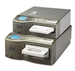
STATIM 5000 G4
STATIM 2000 G4
Поздравляем вас с приобретением кассетного автоклава STATIM®. Автоклав STATIM
- это компактный настольный модуль, предназначенный для стерилизации паром.
Этот кассетный автоклав STATIM G4 полностью соответствует EN13060.
Подробные сведения об установке, эксплуатации и обслуживании устройства
STATIM в полном объеме содержатся в этом руководстве. Ознакомьтесь с этим
руководством и храните его для дальнейшего использования с данным устройством.
Выполняйте инструкции по эксплуатации, техническому обслуживанию и замене
деталей.Содержимое этого руководства подлежит изменениям без предварительного
уведомления с целью отражения изменений и усовершенствований устройств
линейки STATIM .
Устройство STATIM предназначено для стерилизации зубоврачебных и медицинских
инструментов, которые подлежат стерилизации паром. Обращайтесь к разделу
Протокола тестирования в Руководстве, где приведены примеры инструментов
для биологического тестирования, для которых можно использовать STATIM.
Автоклав STATIM не предназначен для стерилизации жидкостей, ткани,
биомедицинских отходов или материалов, не пригодных для стерилизации
паром. Обработка таких материалов может привести к неполной стерилизации и/
или повреждению автоклава. Чтобы получить более подробную информацию о
пригодности инструментов для стерилизации паром, ознакомьтесь с инструкциями
производителя по повторной обработке.
4
2 Важная информация

    2.1 Заявление об ограничении ответственности
    Для паровой стерилизации в автоклаве STATIM используйте только
    дистиллированную воду, полученную методом паровой дистилляции. Не используйте
    деионизированную, деминерализированную или специально фильтрованную воду. Ни
    в коем случае не используйте водопроводную воду.
    Поставка деталей, ремонт и техническое обслуживание автоклава STATIM должны
    осуществляться только авторизованными лицами. Компания SciCan не несет
    ответственности за случайные, фактические или косвенные убытки, возникшие в
    результате ремонта или технического обслуживания автоклава STATIM
    неавторизованными лицами, а также за использование деталей или оборудования,
    поставленных неавторизованными лицами, включая упущенную выгоду,
    производственные, экономические убытки или убытки, возникшие вследствие
    причинения телесных повреждений.
    Ни в коем случае не снимайте крышку автоклава и не вставляйте посторонние
    предметы в отверстия и щели корпуса. Такие действия могут привести к
    повреждению автоклава и/или подвергнуть опасности оператора.
    ВАЖНО! Следуйте местным нормам и правилам, регламентирующим верификацию
    процедуры стерилизации.

    Процедура сушки
    Автоклавы STATIM 2000 G4 и 5000 G4 — это комплексные решения для
    стерилизации упакованных и неупакованных инструментов: быстрая стерилизация и
    быстрая сушка с применением сушильной технологии SciCan Dri-Tec.
    В автоклаве STATIM 2000 G4 применяется конвективное тепло для сушки
    инструментов путем использования тепла, оставшегося в системе после фазы
    стерилизации. Тепло поглощается и передается в кассету, за счет чего правильно
    загруженные в кассету автоклава STATIM инструменты быстро высушиваются.
    В автоклаве STATIM 5000 G4 используется тепло, которое генерируется во
    время фазы стерилизации, а затем поглощается сушильными пластинами. Тепло
    передается с сушильных пластин непосредственно на загруженные инструменты.
    В результате при правильной загрузке кассеты автоклава STATIM сушка происходит
    очень быстро.
    Ознакомьтесь с правилами загрузки инструментов в кассету и использования
    сушильных пластин (STATIM 5000 G4). Эффект быстрой сушки достигается в случае
    точного выполнения правил загрузки инструментов в камеру кассеты.
    О любых серьезных инцидентах следует сообщать производителю и/или в
    компетентные органы по месту проживания пользователя и/или пациента.

                                      5
2 Важная информация                             2000 G4

           2.2 Внешний вид автоклава STATIM 2000 G4
n11 ЖК сенсорный экран                          2           1
                                                                                                                                                                                                                                      Рисунок 1
n21 крышка резервуара/                                                                                                                                                                                                11                          7
n1 водяной фильтр
n31 USB-порт                                                                                                                                                                                              10
n41 выключатель питания
n5 1 разъем кабеля питания
n6 1 выравнивающие ножки
n71 Ethernet-порт
n81 порт вытяжной трубки
n91 компрессор
                                                    3                                                                                                                                                 6        9              8      12   5   4
101 кассета
n
111 биологический фильтр
n                            n
                             121   Порт RS232

   На полях этого                                                                         Ситуация, которая
                                       Потенциальная
                                                                                          может привести к                                                                                                                        Важные
   руководства используются            опасность
                                                                                          механическим                                                                                                                            сведения
   следующие символы:                  для пользователя.
                                                                                          повреждениям.

На устройство нанесены               Осторожно! Горячая                                                                                                                                                            Осторожно! Подробно
следующие символы:                   поверхность и/или горячий пар                                                                                                                                                 ознакомьтесь с руководством.

          Медицинское                 Осторожно! Опасность                                                                                                                                                         Только вода, полученная
          изделие                     поражения электрическим                                                                                                                                                      методом паровой
                                      током. Отсоедините источник                                                                                                                                                  дистилляции
                                      питания перед обслуживанием.

В комплект поставки устройства STATIM 2000 G4 входит перечисленное ниже.
В случае отсутствия любого из элементов немедленно обратитесь к своему дилеру.

                                                                STATim   G4 2000/5000

                  Поддон и крышка                                                                                                                                                                              Руководство оператора
                                                                                      ™
                                                                     AuTOCLAve
                                                                CASSeTTe
                                                                                                                                                                                          reserved.
                                                                                                                                                                  SciCan Ltd . All rights
                                                                                                                                          Rev 8.0. Copyright 2011

                                                                 • Operators Manual
                                                                                                              Operator’s Manual 95-108430

                  кассеты
                                                                                          STATIM G4 2000/5000

                  Стойка для инструментов                                                                                                                                                                      Отводная трубка

                  Сливной флакон                                                                                                                                                                               STAT-DRI PLUS

                  Крепление для крышки                                                                                                                                                                         УКП + 20 эмуляторов
                  флакона                                                                                                                                                                                      стерилизации SciCan

                  Элементы крепления
                                                                                                                                                                                                               USB-накопитель
                  трубки

                  Шнур питания

                                                        6

2 Важная информация                   5000 G4

           2.3 Общие сведения об автоклаве STATIM 5000 G4
n11 ЖК сенсорный экран                 2       1
                                                                                                                                                                                                                11         Рисунок 2
n21 крышка резервуара/
n1 водяной фильтр                                                                                                                                                                            9
n31 USB-порт
n41 выключатель питания
n5 1 разъем кабеля питания
n6 1 выравнивающие ножки
n71 порт вытяжной трубки
n81 биологический фильтр
n91 кассета                                3                                                                                                                                                     6          7    8    10     5   4
101 Порт RS232
n
111 Ethernet-порт
n

                                 Потенциальная                                                Ситуация, которая
   На полях этого
                                 опасность                                                    может привести к                                                                                                       Важные
   руководства используются                                                                   механическим
   следующие символы:            для пользователя.                                                                                                                                                                   сведения
                                                                                              повреждениям.

На устройство нанесены        Осторожно! Горячая                                                                                                                                                      Осторожно! Подробно
следующие символы:            поверхность и/или горячий пар                                                                                                                                           ознакомьтесь с руководством.

          Медицинское         Осторожно! Опасность                                                                                                                                                    Только вода, полученная
          изделие             поражения электрическим                                                                                                                                                 методом паровой
                              током. Отсоедините источник                                                                                                                                             дистилляции
                              питания перед обслуживанием.

В комплект поставки устройства STATIM 5000 G4 входит перечисленное ниже.
В случае отсутствия любого из элементов немедленно обратитесь к своему дилеру.

                 Поддон и крышка
                                                                                                                                                                                                     Шнур питания
                 кассеты
                 Лоток для                             STATim   G4 2000/5000
                                                            AuTOCLAve
                                                       CASSeTTe
                                                                             ™
                                                                                                                                                                                 reserved.
                                                                                                                                                         SciCan Ltd . All rights

                 неупакованных                                                                                                                                                                       Руководство оператора
                                                                                                                                 Rev 8.0. Copyright 2011

                                                        • Operators Manual
                                                                                                     Operator’s Manual 95-108430
                                                                                 STATIM G4 2000/5000

                 инструментов

                 Сливной флакон                                                                                                                                                                      Отводная трубка

                 Крепление для крышки
                 флакона                                                                                                                                                                             STAT-DRI PLUS

                 Элементы крепления                                                                                                                                                                  УКП + 20 эмуляторов
                 трубки                                                                                                                                                                              стерилизации SciCan

                 Стойка для сушильных                                                                                                                                                                USB-накопитель
                 пластин

                                               7
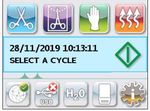
2.4 Обзор сенсорного экрана
      Циклы для полого
  упакованного инструмента

              Цикл для упакованных
                    изделий

                              Резиновые/пластиковые
                                      циклы

                                              Только сушка воздухом.

 Дисплей                                                                  Кнопка
                                                                         остановки

                 мм/дд/гггг    чч:мм:сс

                 ВЫБЕРИТЕ ЦИКЛ

                                                                        Кнопка
                                                                       остановки

   Возможность сетевого                                                 Рисунок 3
  подключения вкл/выкл
   (в активном состоянии
 светится зеленым цветом)

 USB-накопитель соединен/не соединен
   (в активном состоянии светится
           зеленым цветом)

                               Статус уровня воды
                                   и качества

                                                Кассета вставлена
                                               надлежащим образом

                                                            Информация о
                                                        настройках и установке

                                          8

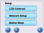
2.5 Обзор меню настроек
Время
1 2 3 --:--
24 ч
Время
14:02
4 5 6
7 8 9
CL 0 EN
Дата
Время
Дата
Летнее время 1 2 3 --/--/--
ДД/ММ/ГГ
01/01/2011
Дата
ВКЛ/ВЫКЛ
Время
4
7
5
8
6
9
CL 0 EN
Летнее время
Дата
ВКЛ/ВЫКЛ Летнее время
ВКЛ/ВЫКЛ
Летнее время
Вкл
мм/дд/гггг чч:мм:сс
ВЫБЕРИТЕ ЦИКЛ ВКЛ/ВЫКЛ По умолчанию Выкл
Гггг/мм/дд xxxxx OK
Гггг/мм/дд xxxxx OK
Гггг/мм/дд xxxxx OK
Недавние
Гггг/мм/дд xxxxx OK
Гггг/мм/дд xxxxx OK
Гггг/мм/дд xxxxx (CFxx)
распечатки Гггг/мм/дд xxxxx (CFxx)
Гггг/мм/дд xxxxx (CFxx)
Гггг/мм/дд xxxxx (CFxx)
Гггг/мм/дд xxxxx (CFxx)
STATIM 5000 S5S2R700
Модель: G4-121101
Недавние
Время 12/24
S/N: 000000A00000
НОМЕР ЦИКЛА : 1
распечатки Задание 12
ч/24 ч
IF: SL00R100
CF xx 12
НЕДОПУСТИМОЕ Формат
Недавниедаты
КАЧЕСТВО ВОДЫ. Время 12/24
распечатки По умолчанию 24
Формат даты
Время 12/24
Формат даты
ММ/ДД/ГГГГ
Формат даты По умолчанию
ДД/ММ/ГГГГ
Язык
Французский язык
Язык По умолчанию
Английский язык
№ устройства
Язык
№ установки
1 2 3 000
Качество воды
№ устройства 4 5 6
Язык 7 8 9
CL 0 EN
Качество воды
№ устройства
xx.x мкСим
Качество воды xx.x м.д.
УРОВЕНЬ ВОДЫ
STATIM 5000 S5S2R700
Модель: G4-152302
Серийный номер
Сер. № 000000A00000
НОМЕР ЦИКЛА 1
ЕСЛИ: SL00R100
CF xx
КАЧЕСТВО ВОДЫ
НЕПРИЕМЛЕМО
Тип принтера
Серийный номер
Тип принтера
Скорость передачи Последовательный
принтер
Тип
в принтера
бодах
Серийный номер По умолчанию
Без принтера
Скорость передачи
Тип принтера
в бодах
Скорость
передачи в бодах
Скорость передачи
1200
в бодах По умолчанию
9600
9

2.5 Обзор меню настроек(прод.)
Конец строки
CR/LF
CR
Код серии CR/LF
По умолчанию
Настройки принтера
Код серии CR/LF
график
Пользователь
принтера ° буква
Принудительный 1 2 3 000
Настройки принтера
процесс
4 5 6
Код серии CR/LF
график 7 8 9
CL 0 EN
Принудительный
Настройки принтера
процесс
график Вынужденный
процесс
Принудительный
Вкл.
процесс По умолчанию Выкл
Настройка ПИН- Настройка
кода ПИН-кода
Пользователь х
ПИН-код обновлен
0000
1 2 3
Новый ПИН-код xxxx
Пользователь 4
7
5
8
6
9
OK
CL 0 EN
Темы
Пользователь
Темы Темы
Изменить тему Statim Silver
Скринсейвер
Темы Обновить тему
По умолчанию
Statim NG
Скринсейвер
Обновить тему Обновить тему Обновить тему
Пользователь ПОДОЖДИТЕ
Поиск темы ...
P04_B091
P04_B092
P04_B093
P04_B094
Готово
Обновить Обновить Обновить
Темы
Заставка
3 мин
Скринсейвер По умолчанию 2
мин.
Контраст ЖКД
xx
Контраст ЖКД По умолчанию
100
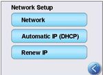
Настройка сети
Контраст ЖКД
Настройки сети Автоматическое IP
(DHCP)
Кнопка звукового Автоматическое IP
(DHCP) Выкл.
Настройка
сигнала сети
Обновить IP
По умолчанию
Вкл.
Кнопка звукового
сигнала Обновить IP
Контраст ЖКД DHCP
Ссылка: Выкл.
Связь: dhcp
IP: 0.0.0.0
Настройка сети Обновить IP
Кнопка звукового
сигнала
Кнопка звукового
Выкл.
сигнала По умолчанию
Вкл.
Громкость
звукового сигнала
80
Громкость
звукового сигнала По умолчанию
100
Уровень
Громкость
звукового сигнала
Уровень
10
3 Настройка вашего STATIM

     3.1 Расположение и подключение вашего устройства
        Расположение вашего устройства
     На эксплуатационные характеристики автоклава STATIM могут влиять несколько
     факторов. Проанализируйте эти факторы и выберите подходящее место для
     установки устройства.

     •НеТемпература  и влажность
         устанавливайте устройство STATIM под прямыми солнечными лучами и вблизи
     источников тепла (например, вентиляторов и радиаторных батарей).
     Рекомендованная рабочая температура: 15–25 ˚С при влажности 25–70%.

     •Вентиляционные
        Зазор
                     отверстия и решетки вашего автоклава STATIM не должны
     быть закрыты или заблокированы. Между верхней, боковыми и задней панелями
     автоклава и любыми стенами или перегородками должен оставаться зазор не менее
     50 мм. За дополнительной информацией по зазорам обращаться к Спецификациям.

     •Эксплуатация
        Вентиляция
                   устройства STATIM должна осуществляться в чистом,
     незапыленном помещении.

     •Автоклав
        Рабочая поверхность
               STATIM необходимо установить на плоскую, горизонтальную,
     водоотталкивающую поверхность. Ни в коем случае не устанавливайте устройство на
     наклонную поверхность.

     •Автоклав
        Электромагнитное излучение
               STATIM прошел испытания и соответствует действующим стандартам по
     допустимому электромагнитному излучению.  Сам автоклав не излучает радиацию,
     но на него может оказывать воздействие другое излучающее оборудование.
     Рекомендуется устанавливать устройство вдали от потенциальных
     источников наводок.

     •Используйте
        Электрические соединения
                  правильно заземленные и снабженные предохранителями источники
     питания с номинальным напряжением, соответствующим указанному на этикетке,
     размещенной на задней панели автоклава STATIM. Не используйте сдвоенные и т. п.
     розетки. Если вы используете сетевой фильтр, подключайте к нему только один
     автоклав STATIM .

        Заземление вашего устройства
     Чтобы заземлить устройство STATIM,подсоедините шнур питания к электрической
     розетке переменного тока сзади устройства. Убедитесь, что выключатель в
     положении ВЫКЛ и подсоедините устройство к источнику питания.

                                      11
3 Настройка вашего STATIM

     3.2 Выравнивание устройства
     При размещении устройства на рабочей поверхности убедитесь, что она стабильна, и
     что все ножки соприкасаются с поверхностью стола. Это предотвратит произвольное
     смещение автоклава. Далее с помощью пузырькового уровнемера в меню настроек
     скорректируйте три уровня ножек, чтобы дренировать устройство надлежащим
     образом. Чтобы воспользоваться пузырьковым индикатором уровня на главном
     экране, выполните следующие шаги:

     1.

     2. Прокрутите к    Уровень        и выберитero.
     3. Настройте выравнивающие ножки, чтобы
        переместить пузырек. Разместите пузырек
        в нижнем правом квадранте целевого
        положения. Это обеспечит правильный слив
        жидкости. Нажмите STOP (ОСТАНОВКА),
        чтобы выйти и вернуться к меню выбора
        цикла. Когда установка правильно выравнена,
        цвет пузырька изменится с красного
        на зеленый.

                                      12
3 Настройка вашего STATIM

     3.3 Подсоединение сливного флакона
     Сливной флакон 1   используется для сбора отработанной воды после ее
     преобразования в пар и слива из кассеты.  Чтобы подсоединить сливной флакон к
     автоклаву STATIM, выполните перечисленные ниже действия (см. рис. 4).

     1. Вставьте отводную 2 трубку в                                5000 G4
        штуцер 3 на задней панели
        устройства и осторожно потяните,
        чтобы проверить герметичность.
     2. Обрежьте трубку до нужной длины                     2
        и вставьте крепление сливного
        флакона 4 на место.                                                         3
                                                        5
     3. Вставьте свободный конец трубки в
        отверстие в крышке сливного
        флакона и затяните крепление                                                    4
        рукой.  Не перекручивайте
        отводную трубку.
     4. Открутите крышку и змеевик
        медного конденсатора 5 от                                       1
        сливного флакона.  Крышка и
        змеевик должны сниматься
        вместе.
     5. Заполните сливной флакон водой
        до отметки минимального уровня
        (MIN) и установите крышку в сборе с
        медным конденсатором.                                   3
                                              2000 G4
        Опорожняйте сливной флакон                                  2
        часто во избежание неприятных
                                                                                5
        запахов и обесцвечивания
        содержимого. (Во избежание этого
        можно добавить в сливной флакон
        дезинфицирующее средство низкой
        концентрации, приготовленное
        согласно инструкциям
        производителя).  Как минимум,                                       1
        опорожняйте сливной флакон после
        каждого заполнения резервуара.
     6. Поставьте сливной флакон рядом       Рисунок 4
        с автоклавом. Храните флакон
        под автоклавом. Трубку можно
        пропустить через отверстие (диаметром 8 мм) в столешнице и закрепить
        нейлоновыми зажимами, входящими в комплект поставки.

                                       13
3 Настройка вашего STATIM

     3.4 Заполнение водяного резервуара
     При заполнении резервуара используйте только воду, полученную методом паровой
     дистилляции и содержащую менее 5 м. д. общей массы растворенных твердых
     веществ (и обладающую проводимостью не
     более 10 мкСм/см).  Посторонние примеси         1
     и добавки, содержащиеся в воде из других
     источников, приведут к появлению
     сообщения об ошибке на ЖК-дисплее.
     Чтобы заполнить резервуар, выполните
     описанные ниже действия (см. рис. 5)
     1. Снимите крышку резервуара 1 .
     2. Залейте воду, полученную методом
        паровой дистилляции, в резервуар почти
        до полного заполнения (максимум 4 л).
        Во избежание пролива воды
                                                   Рисунок 5
        используйте воронку.
     3. Наденьте и закрепите крышку.

     3.5 Заполнение насоса
     Чтобы заполнить насос автоклава STATIM ,
     выполните перечисленные ниже действия.
     1. Переместите устройство к краю рабочей
        поверхности. Передние выравнивающие        3
        ножки должны находиться на расстоянии
        приблизительно в 12 мм от края.                2
     2. Поднимите передний левый угол                       Рисунок 6
        устройства и извлеките трубку 2 из
        зажима, расположенного на нижней панели устройства.
     3. Вытяните сливную трубку так, чтобы ее свободный конец можно было опустить в
        емкость с водой.
     4. Заполните резервуар водой, полученной методом паровой дистилляции.
     5. Извлеките заглушку     из
                            3     конца сливной трубки и подождите 30 секунд, чтобы
        вода стекла из трубки в емкость.  Когда вода потечет устойчивой струей, вставьте
        заглушку на место.
     6. Поднимите передний левый угол автоклава и вставьте трубку в зажим,
        расположенный на нижней панели устройства.  Задвиньте остаток трубки обратно
        в специально предназначенное для этого пространство.
     Проверьте, плотно ли установлена заглушка в сливной трубке.

                                       14
3 Настройка вашего STATIM

     3.6 Настройка времени
     1.

     2. Прокрутите к          Время          и выберитero.
     3. На экране «ВРЕМЯ» для установки времени воспользуйтесь клавиатурой.
          Нажмите     EN   , чтобы сохранить выбор и   вернуться в меню «Настройки».
     4. Чтобы ваше устройство отображало время в 12-часовом формате (24-часовой
          формат настроен по умолчанию), откройте меню «Настройки» и при помощи
                  пролистайте до «ВРЕМЯ 12/24» и переключите настройку на 12. Нажмите
             , чтобы сохранить выбор и вернуться в меню «Настройки».
     5. Чтобы активировать летнее время (ЛВ), рекомендуемое, если ваше устройство
          подсоединено к сети, перейдите в меню «Настройки» и при помощи
          пролистайте до ЛВ ВКЛ/ВЫКЛ и сделайте выбор. Воспользуйтесь
                 для переключения между ЛВ ВКЛ или ВЫКЛ и нажмите
             , чтобы сохранить выбор и вернуться в меню «Настройки».

     3.7 Настройка даты
     1.

     2. Прокрутите к          Дата           и выберитero.
     3. На экране «ДАТА» для установки даты воспользуйтесь клавиатурой. Нажмите
           EN   , чтобы сохранить выбор и вернуться в меню «Настройки».
     4. Чтобы поменять форматы даты, вернитесь в меню «Настройки» и воспользуйтесь
                 , чтобы прокрутить к «ФОРМАТ ДАТЫ». Нажмите на него, и используя
          подсказки, установите дату в желаемом формате. Нажмите   , чтобы сохранить
          выбор и вернуться в меню «Настройки».

     3.8 Настройка языка
     Сообщения, которые показывает STATIM , могут отображаться на разных
     языках. Чтобы изменить текущий язык, выполните перечисленные ниже действия:

     1.

     2. Прокрутите к          Язык           и выберитero.
     3. На экране ЯЗЫК нажмите          , чтобы пролистать перечень языков.
          Когда вы найдете желаемый язык, нажмите     , чтобы сохранить свой выбор и
          вернуться в меню «Настройки».

                                            15
3 Настройка вашего STATIM

     3.9 Присвоение идентификатора автомату
     1.

     2. Прокрутите к            № установки         и выберитero.
     3. При помощи клавиатуры выберите не более трех цифр, которые будут
          использоваться в качестве идентификатора автомата. Нажмите                 EN   , чтобы
          сохранить выбор и     вернуться в меню «Настройки».
     3.10 Создание идентификационного номер пользователя и
           ПИН-кода
     1.

     2. Прокрутите к            Пользователь        и выберитero.
     3. На экране «ЗАДАНИЕ ПИН-КОДА» можно присвоить до четырех ПИН-кодов.
          Выберите одну из пользовательских иконок для присвоения ПИН-кода.
     4. С помощью клавиатуры присвойте ПИН-код, содержащий до четырех цифр, и
          нажмите      EN   , чтобы сохранить            и перейти к экрану подтверждения.

      Настройка ПИН-                     Настройка
      кода                               ПИН-кода                                Пользователь х
                                                              0000               ПИН-код обновлен
                                               1     2   3
                                                                                 Новый ПИН-код xxxx
                                               4     5   6

                                               7     8   9                                          OK

                                               CL    0   EN

     5. Если отображаемая на экране подтверждения информация верна, нажмите ОК,
          чтобы вернуться к экрану «ПИН-код пользователя». Для того, чтобы внести
          исправления, нажмите на ПИН-код пользователя, который вы хотите изменить,
          и повторите описанные выше действия.
     3.11 Настройка обязательных этапов процесса
     При активации обязательных этапов процесса пользователь обязан ввести ПИН-
     код в начале и в конце цикла. Для использования обязательных этапов процесса
     сначала необходимо присвоить идентификатор пользователя и ПИН-код. Инструкции
     по установке идентификатора пользователя и ПИН-кода приведены в Разделах
     3.10 - Создание идентификатора пользователя и ПИН-кода. Чтобы активировать
     обязательные этапы процесса, выполните следующие действия:

     1.

     2. Прокрутите к          Вынужденный            и выберитero.
                              процесс
     3. Для ВКЛЮЧЕНИЯ и ВЫКЛЮЧЕНИЯ обязательных этапов процесса используются
          кнопки            . Нажмите    , чтобы сохранить ваш выбор и вернуться в меню «Настройки».
     ПРИМЕЧАНИЕ. Любой пользователь может прервать цикл и извлечь кассету даже
     при активированной функции обязательных этапов процесса. Однако данные о
     цикле будут содержать информацию о том, что несанкционированный пользователь
     прервал цикл и/или об извлечении кассеты.
                                                    16
3 Настройка вашего STATIM

     3.12 Смена темы сенсорного экрана
     Темы сенсорного экрана STATIM G4 (т.е. пиктограммы и фоновые цвета) можно
     выбрать из предоставленных вариантов или можно загрузить дополнительные темы
     по мере их доступности в SciCan с помощью USB-порта. Чтобы изменить текущий
     выбор темы, выполните следующие действия:

     1.

     2. Прокрутите к        Темы           и выберитero.
     3. Отсюда можно выбрать         Изменить тему   предварительно загруженные темы или
            Обновить тему   перейти к новой теме, которую можно загрузить с помощью
          USB-порта.

     4. На экране     Изменить тему  при помощи          просмотрите доступные
          варианты. Во время прокручивания каждая тема будет просматриваться на
          сенсорном экране. Нажмите     , чтобы выбрать тему и вернуться в меню
          «Настройки».

     5. Для обновления статуса темы, доступной в SciCan, загрузите тему на свой
          настольный компьютер и сохраните файлы на портативный USB-накопитель.
          Вставьте устройство в порт STATIM и на экране UPGRADE THEME (Обновить
          тему) нажмите Повысить статус .

     5.1 Устройство загрузит файлы прямо с USB-накопителя. Не извлекайте USB-порт во
          время загрузки файлов (это занимает по крайней мере 10 минут). По завершении
          на экране отобразится уведомление ‘Done’ («Завершено»). Эта новая тема будет
          доступна из вашего меню ТЕМЫ.

     5.2 Нажмите       , чтобы выбрать эту тему и вернуться в экран «Настройки».

     3.13 Настройка задержки скринсейвера
     Чтобы изменить время активации скринсейвера,
     выполните следующие действия:

     1.

     2. Прокрутите к        скринсейвера   и выберитero.
     3. Воспользуйтесь          , чтобы прокрутить через разные варианты времени.
          Когда вы найдете желаемый вариант времени, нажмите на него. Нажмите         ,
          чтобы сохранить выбор и вернуться в меню «Настройки».

                                           17
3 Настройка вашего STATIM

     3.14 Настройка контраста экрана
     Сенсорный экран STATIM G4 калиброванный под уровень освещение большинства
     стерилизационных центров. Если вам необходимо отрегулировать контраст в
     зависимости от освещения в вашем офисе, выполните следующие действия:

     1.

     2. Прокрутите к      Контраст ЖКД    и выберитero.
     3. Воспользуйтесь          , чтобы прокрутить разные варианты контраста. Когда
          вы найдете желаемый вариант контраста, нажмите на него. Нажмите      , чтобы
          сохранить выбор и вернуться в меню «Настройки».

     3.15 ВКЛЮЧЕНИЕ и ВЫКЛЮЧЕНИЕ кнопки звука
     По заводской установке при нажатии кнопок STATIM G4 издает звук. Если вы
     желаете отключить звук кнопок, выполните следующие действия:
     ПРИМЕЧАНИЕ. ВЫКЛЮЧЕНИЕ кнопки звука НЕ выключает другие аварийные
     сигналы и звуковые оповещения по рабочим циклам.

     1.

     2. Прокрутите к      Звуковой сигнал ВКЛ/ВЫКЛ      и выберитero.
     3. При помощи           выберите ВКЛ. или ВЫКЛ, и нажатием на них сделайте
          необходимый выбор.
          Нажмите     , чтобы сохранить выбор и вернуться в меню «Настройки».

     3.16 Настройка громкости звукового сигнала кнопок
     Если вы хотите отрегулировать громкость звуковых сигналов, выполните
     следующие действия:

     1.

     2. Прокрутите к      Громкость звукового сигнала   и выберитero.
     3. При помощи            пролистайте настройки звука. Выберите желаемую
          настройку, нажав на нее. Нажмите     , чтобы сохранить выбор и вернуться
          в меню «Настройки».

                                         18
3 Настройка вашего STATIM
3.17 Настройка и использование веб-портала STATIM G4
Веб-портал STATIM G4 напрямую подключается к STATIM в вашей локальной
сети. Портал защищен брандмауэром и недоступен для сторонних пользователей (если
у них нет Кода удаленного доступа. Дополнительная информация приведена в Разделе
7. Извлечение кода удаленного доступа). Веб-портал обеспечивает информацию о цикле
в режиме реального времени и архивные записи о стерилизации для данной конкретной
установки. Отсюда можно распечатать отчеты, настроить установки для уведомлений
электронной почты и проводить поиск историй циклов. Для настройки веб-портала,
следуйте инструкциям, доступным на вкладке портала «ПОМОЩЬ».
3.18 Подключение к сети
STATIM G4 оснащен Ethernet-портом 10/100Base-T, размещенным на задней
панели устройства. Чтобы подсоединить устройство STATIM к сети при помощи
маршрутизатора, выполните следующие действия:
1. Подключите сетевой кабель к Ethernet-порту на задней панели автомата. Если в
вашем офисе используется маршрутизатор, он должен автоматически присвоить
вашему автомату IP-адрес. Вы узнаете IP-адрес, присвоенный вам, когда исчезнет
красный символ «Х» на пиктограмме «Сеть».
ПРИМЕЧАНИЕ. В некоторых случаях, если у вас нет маршрутизатора, например,
при совместном использовании сети в Windows, возможно, вам придется присвоить
выделенный или «статический» IP-адрес. Для присвоения статического IP-адреса
свяжитесь с администратором вашей локальной сети.
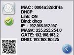
2. Нажмите на пиктограмму «Сеть» на главном экране. На экране «Сеть» появится
информация о возможностях соединения автомата STATIM, включая его IP-адрес.
мм/дд/гггг чч:мм:сс
ВЫБЕРИТЕ ЦИКЛ
19
3 Настройка вашего STATIM

     3. Чтобы получить доступ к веб-порталу вашего автомата, введите IP-адрес,
        отображаемый на сенсорном экране, в браузер любого устройства, подключенного
        к сети. Вы узнаете IP-адрес, присвоенный вам, когда исчезнет красный символ
        «Х» на пиктограмме «Сеть». Когда пиктограмма «Сети» активна (например, при
        отправке электронного письма), она становится зеленого цвета.

     ПРИМЕЧАНИЕ. При подключении к мобильному устройству воспользуйтесь
     QR-кодом.

     ПРИМЕЧАНИЕ. Время подсоединения меняется в зависимости от скорости сети.
     Установление первого соединения может занять больше времени.

     3.19 Подсоединение к беспроводной сети
     Модели STATIM G4 имеют функцию беспроводного подключения блоков к сети G4,
     которая дополняет функцию подключения к сети через кабель, также доступную
     для блоков STATIM G4. STATIM G4 WiFi — это простая настройка и надежное
     подключение к сети G4.

     1. Нажмите значок сети на главном экране.

     2. Выберите WiFi, выберите свою сеть и введите пароль.

     ПРИМЕЧАНИЕ. вы можете в любое время изменить свои параметры подключения

     3.20 Резервирование IP-адреса для вашего STATIM
     Когда ваш STATIM соединен с маршрутизатором на вашей сети, ему присваивается
     уникальный IP-адрес. Если связь между вашим STATIM и маршрутизатором потеряна
     (например, отключение электричества, повторный пуск STATIM или маршрутизатора)
     при повторном подключении может быть получен другой IP-адрес. Это может
     привести к тому, что ранее сохраненные закладки и ссылки станут неправильными.
     Для установки «постоянного» IP-адреса (также известного как «DHCP/IP/
     Резервирование адреса») необходимо выполнить следующие шаги:
     1. Выбрать пиктограмму «Сеть» на сенсорном экране STATIM G4 и записать номер
        GATE (маршрутизатор местного IP). Ввести этот номер GATE в адресную строку
        вашего веб-браузера для доступа в настройки маршрутизатора. (ПРИМЕЧАНИЕ:
        вам потребуется сетевой пароль,чтобы изменить настройки).

        мм/дд/гггг   чч:мм:сс

        ВЫБЕРИТЕ ЦИКЛ

                                       20
3 Настройка вашего STATIM

     ПРИМЕЧАНИЕ. Доступ к этому экрану отличается для каждого маршрутизатора.
     Обратитесь в Руководству пользователя маршрутизатора или к своему сетевому
     администратору для получения более подробной информации. Компания SciCan
     рекомендует использовать беспроводный маршрутизатор N D-Link DIR-615.
     2. Используйте функцию «DHCP/IP/Резервирование адреса» для присвоения своему
        STATIM «постоянного» IP-адреса. (ПРИМЕЧАНИЕ: Каждый производитель может
        использовать различную номенклатуру; эти настройки могут называться: «HCP-
        резервирование», «IP-резервирование» или «резервирование адреса»).
     3. Вам необходимо выбрать соответствующее устройство для приложения этих
        настроек. Название вашего устройства по умолчанию будет: ‘statim_###’.
     ВАЖНО! Обратитесь к своему сетевому администратору для более подробной
     информации.

     3.21 Подготовка устройства к использованию.
     После установки устройства и перед стерилизацией инструментов, провести два
     цикла полого упакованного инструмента (3,5 мин.) (см. раздел 5.2 - Рабочий цикл).
     Извлечь кассету после ее охлаждения. Очистить верх (крышку) и низ (лоток),
     протерев с помощью мягкой ткани внутреннюю поверхность, а затем тщательно
     сполоснуть водопроводной водой. Когда кассета будет чистой и сухой, накрыть
     внутреннюю поверхность STAT-DRI PLUS.
     Утилизация упаковки и списанных товаров
     Ваш товар поставляется в картонной коробке. Пожалуйста, разберите ее и направьте
     на переработку или утилизацию в соответствии с требованиями муниципального
     законодательства.

     Списанный стерилизатор не подлежит утилизации вместе с обычным бытовым
     мусором. Это может нанести вред людям и окружающей среде. Упаковка
     применялась в сфере здравоохранения, поэтому она может представлять небольшой
     риск контроля инфекций. Также она содержит некоторые регенерируемые
     материалы, которые можно извлечь и повторно использовать для изготовления
     других продуктов. Чтобы узнать больше о политике и программах, регулирующих
     утилизацию электроприборов, обратитесь в свое городское самоуправление.

                                        21
4 Использование кассет и подготовка инструментов

     4.1 Использование кассет STATIM 2000 G4
     Соблюдайте осторожность при извлечении кассеты после завершения цикла
     обработки, так как ее металлические части будут горячими, а внутри может
     находится горячий пар.

        Открытие кассеты:
     1. Возьмитесь за ручку кассеты так, чтобы                       защелка кассеты
        большие пальцы располагались сверху на
        замке кассеты.
     2. Прижмите защелку кассеты.
     3. Поднимите крышку кассеты и снимите ее
        с петли.
                                                           Рисунок 7
     4. Положите крышку внутренней стороной вверх.

        Закрытие кассеты:
     1. Совместите язычок петли на крышке кассеты с пазом петли на задней
        части поддона.
     2. Когда вы начнете закрывать крышку, язычок и паз петли войдут в зацепление.

        Чтобы вставить кассету в автоклав STATIM 2000 G4:
     1. Разместите заднюю часть кассеты в устройстве.
     2. Слегка надавите, пока не услышите щелчок и проверьте не изменилась ли ЖК
        иконка с    на     .

     При установке кассеты в автоклав STATIM  не применяйте чрезмерную силу, чтобы
     не повредить внутренние детали.

     ПРИМЕЧАНИЕ. На экране будет отображено            , если кассета неправильно
     вставлена в устройство.

        Чтобы извлечь кассету:
     1. Возьмитесь за ручку двумя руками и вытащите кассету из автоклава.
     2. Полностью извлеките кассету из автоклава и положите ее на твердую
        поверхность.

        Отсоединение кассеты:
     Если автоклав не используется, кассету необходимо отсоединить.  Чтобы отсоединить
     кассету, возьмитесь за ручку и тяните кассету наружу до тех пор, пока ручка кассеты не
     окажется на расстоянии 15–20 мм (1/2 - 3/4”) от передней панели STATIM .

        Использование осушающего реагента STAT-DRI PLUS
     Обработка внутренней поверхности кассеты осушающим реагентом STAT-DRI PLUS,
     который входит в комплект поставки устройства, оптимизирует процесс сушки  (реагент
     можно заказать в компании SciCan, номер для заказа 2OZPLUS, 8OZPLUST, 32OZPLUS).

                                         22
4 Использование кассет и подготовка инструментов

     4.2 Использование кассет STATIM 5000 G4
     Соблюдайте осторожность при извлечении кассеты после завершения цикла
     обработки, так как ее металлические части будут горячими, а внутри может
     находится горячий пар.

        Открытие кассеты:
     1. Поднимите ручку для переноски 2 .
     2. Возьмитесь за ручку кассеты с
        обеих сторон. 1
                                                2
     3. Вставьте указательные пальцы в
        отверстия, а большие пальцы положите
        на углубления для больших пальцев.
                                                                             1
     4. Большими пальцами давите вниз, а
        указательными тяните вверх до тех
        пор, пока крышка не откроется.
                                                                         2
     5. Поднимите крышку кассеты
        и отсоедините ее от поддона.
        Положите крышку внутренней
        стороной вверх.

        Закрытие кассеты:
     1. Совместите язычок петли на крышке
        с пазом петли на поддоне.
     2. Когда вы начнете закрывать крышку,
        язычок и паз петли войдут в
        зацепление.
     3. Опустите ручку для переноски. 2

        Чтобы вставить кассету в
        автоклав STATIM 5000 G4:
     1. Возьмитесь одной рукой за ручку
        кассеты, а другой рукой за ручку для    Рисунок 8
        переноски, как показано на рисунке 8.
     2. Вставьте заднюю часть кассеты в автоклав и
        опустите ручку для переноски.
     3. Слегка надавите, пока не услышите щелчок и проверьте не изменилась ли ЖК
        иконка с    на     .

     При установке кассеты в автоклав STATIM не применяйте чрезмерную силу, чтобы
     не повредить внутренние детали.
     ПРИМЕЧАНИЕ. На экране будет отображено          , если кассета неправильно
     вставлена в устройство.

                                         23
4 Использование кассет и подготовка инструментов

        Чтобы извлечь кассету:
     1. Возьмитесь за ручку одной рукой и вытащите кассету из автоклава.
     2. После того как кассета будет извлечена из автоклава, возьмитесь за ручку для
        переноски свободной рукой и поднимите ее вверх.
     3. Полностью извлеките кассету из автоклава и положите ее на твердую
        поверхность.

        Отсоединение кассеты
     Если автоклав не используется, кассету необходимо отсоединить. Чтобы отсоединить
     кассету, возьмитесь за ручку и тяните кассету наружу до тех пор, пока ручка кассеты не
     окажется на расстоянии 15–20 мм (1 / 2 - 3 / 4”) от передней панели STATIM.

     4.3 Использование сушильных пластин с STATIM 5000 G4
     Кассета STATIM 5000 G4 поставляется с двумя
     стойками, в одной из которых имеются сушильные
     пластины.  Используйте стойку с сушильными
     пластинами, чтобы интенсифицировать сушильный
     процесс для упакованных инструментов.

                                                          Рисунок 9

     4.4 Подготовка и загрузка инструментов
     Перед тем, как загружать инструменты в автоклав STATIM, ознакомьтесь
     с инструкциями производителя по стерилизации.

        Чистка инструментов
     Очистите и промойте все инструменты перед тем, как загружать их в кассету.
     Остатки дезинфицирующих веществ, а также твердые частицы могут помешать
     надлежащей стерилизации и повредить инструменты, кассету и сам автоклав
     STATIM. Смазанные инструменты необходимо тщательно протереть и удалить
     излишки смазки перед загрузкой.

        Неупакованные инструменты
     Разложите неупакованные инструменты на лотке, распределяя их как можно
     равномернее.

                                         24
4 Использование кассет и подготовка инструментов

        Упакованные инструменты (обернутые один раз)
     Уложите инструменты в пакеты для автоклавирования в один слой в соответствии
     с инструкциями производителя. Разместите лоток для инструментов в кассете таким
     образом, чтобы упакованные инструменты находились на расстоянии приблизительно
     6 мм над поверхностью кассеты.  Уложите упакованные инструменты на лоток так,
     чтобы они не касались друг друга.  Чтобы сохранить стерильность, перед тем как
     использовать инструменты и/или убрать их на хранение, убедитесь, что все
     упаковки сухие.
     Необходимо также следить за тем, чтобы общий вес загруженных пакетов не
     превышал 1,5 кг для STATIM 5000 G4 или 1,0 кг дляSTATIM 2000 G4.
     Для STATIM 2000 G4:

     Не рекомендуется использовать в автоклаве STATIM тканевые упаковки.
     Компания SciCan рекомендует использовать бумажные / бумажно-пластиковые
     / пластиковые пакеты для автоклавирования, произведенные в соответствии со
     стандартом EN 868. Инструменты должны лежать в пакетах свободно, чтобы пар
     мог попадать на всю поверхность инструментов.

     Для STATIM 5000 G4:

              Лоток для неупакованного инструмента, рассчитанный на 10 пластин Stat-
              Dri, может вместить 10 пакетов для автоклавирования.

        Резиновые и пластиковые инструменты
     В автоклаве STATIM разрешается стерилизовать следующие материалы:
     нейлон, поликарбонат (Lexan™), полипропилен, ПТФЭ (Teflon™), ацетал (Delrin™),
     полисульфон (Udel™), полиэфиримид (Ultem™), силиконовую резину и полиэфир.
     При загрузке в лоток пластиковых и резиновых инструментов оставляйте
     свободное пространство между инструментами и стенками кассеты. Таким образом
     обеспечивается распределение пара по всем поверхностям и эффективность сушки.

                                       25
4 Использование кассет и подготовка инструментов

     Следующие материалы запрещается стерилизовать в автоклаве STATIM:
     полиэтилен, АБС, стирол, целлюлозные пластмассы, ПВХ, акрил (Plexiglas™), PPO
     (Noryl™), латекс, неопрен и другие аналогичные материалы.
     Стерилизация этих материалов может привести к повреждению инструмента
     или оборудования.  Если вы не уверены в материале или конструкции вашего
     инструмента, перед его загрузкой в автоклав STATIM , обязательно запросите
     дополнительную информацию у производителя инструмента.

        Все инструменты
     Автоклав STATIM НЕ предназначен для стерилизации ткани, жидкостей или
     биомедицинских отходов.  Инструменты остаются стерильными после успешного
     завершения цикла стерилизации до отсоединения кассеты от автоклава.
     Неупакованные инструменты после контакта с окружающей средой
     перестают быть стерильными.  Если требуется стерильное хранение,
     стерилизуемые инструменты необходимо упаковать в пакеты для автоклавирования
     в соответствии с инструкциями производителя инструмента.
     В этом случае необходимо выполнить цикл стерилизации для упакованного
     инструмента с фазой воздушной сушки.
     Лучший практический совет: перед дальнейшим использованием убедитесь, что
     инструменты (как упакованные, так и неупакованные) полностью высушены.
      Упакованные или разложенные в пакеты инструменты не должны соприкасаться
     друг с другом; это обеспечит эффективную стерилизацию и сушку.

     Компания SciCan рекомендует пользователю тщательно выбирать подходящий
     цикл стерилизации в соответствии с рекомендациями руководящих органов,
     ответственных за санитарно-эпидемиологическое состояние, а также местными
     нормативными указаниями / рекомендациями.

     Примечания для использования в офтальмологии
     В области офтальмологии надлежащая упаковка хирургических инструментов
     снижает возможность контакта инструментов с остатками обработки в ходе цикла
     стерилизации. Ввиду высокой чувствительности некоторых типов хирургии (особенно
     в офтальмологии), компания SciCan рекомендует, чтобы все инструменты были
     обычным образом упакованы и обработаны в ходе упаковочного цикла стерилизации.
     Эта практика является рекомендуемым подходом для большинства стерильных
     хирургических процедур и указана в многих ведущих публикациях и руководствах по
     контролю инфекций.

     4.5 Использование биологических и химических индикаторов
     В каждую упаковку (или поверх нее) и загрузку следует добавлять химические
     индикаторы процесса, предназначенные для использования в паровых
     стерилизаторах.  Кроме того, рекомендуется еженедельно использовать
     биологические индикаторы, для того чтобы убедиться, что инструменты
     действительно прошли стерилизацию.

                                       26
4 Использование кассет и подготовка инструментов

     4.6 Веса приспособлений
                      Инструмент                  Стандартный вес приспособления
        Ножницы                                     30 г
        Инструмент для снятия зубного камня         20 г
        Щипцы                                       15 г
        Стоматологический наконечник                40–60 г
        Лоток для упакованных инструментов          260 г
        Лоток для неупакованных инструментов        225 г
        Аспирационная канюля                        10 г
        Пластиковое стоматологическое зеркало       8г
        Ложка для изготовления слепка               15–45 г
        Пластиковое кольцо для рентгенографии       20 г

     ПРИМЕЧАНИЕ. Указанные выше значения веса используются только для справки.
     Точный вес инструментов указан в спецификациях, предоставленных
     производителем.

                                     27
5. Использование STATIM

     Перед использованием STATIM в первый раз, убедитесь, что резервуар и насос
     заполнены. См. разделы 3.4 Заполнение резервуара и 3.5 Заполнение насоса
     для дополнительных инструкций.

     5.1 Выбор цикла
     Автоклавы STATIM 2000 G4 и 5000 G4 имеют семь циклов стерилизации, каждый
     из которых предназначен для стерилизации с использованием указанных ниже
     параметров. Каждый цикл выбирается нажатием кнопок циклов для НЕУПАКОВАННЫХ
     инструментов, УПАКОВАННЫХ инструментов или РЕЗИНЫ/ПЛАСТИКА.

     Далее приводится описание типов инструментов, требований по стерилизации и
     диаграммы характеристик для каждого из циклов.Требования к размеру нагрузки
     указаны в разделе «Протокол тестирования».

     5.1.1 Циклы для неупакованного инструмента
     STATIM 2000 G4 и 5000 G4 имеют два цикла стерилизации типа S при 134 °C и один
     цикл стерилизации типа N при 134 °C для НЕУПАКОВАННОГО инструмента.  По
     окончании фазы стерилизации начинается фаза воздушной сушки,
     которая длится один час. Тип цикла S используется для стерилизации твердых и
     полых металлических инструментов, таких как стоматологические наконечники.
                               ПОЛЫЕ НЕУПАКОВАННЫЕ ИНСТРУМЕНТЫ (S) 134 ˚C / 3,5 мин

                               ПОЛЫЕ НЕУПАКОВАННЫЕ ИНСТРУМЕНТЫ (S) 134 ˚C / 18 мин

     Тип цикла S используется для стерилизации твердых металлических инструментов,
     таких как щипцы, сверла, инструменты для удаления зубного камня
     и пинцеты.
                                ТВЕРДОТЕЛЬНЫЕ НЕУПАКОВАННЫЕ ИНСТРУМЕНТЫ (S) 134 ˚C / 3,5 мин

     Для выбора одного из этих циклов: Нажмите кнопку цикла для НЕУПАКОВАННОГО
     инструмента, чтобы прокрутить список доступных циклов.

         ПОЛЫЕ НЕУПАКОВАННЫЕ                          ПОЛЫЕ НЕУПАКОВАННЫЕ
         ИНСТРУМЕНТЫ                                  ИНСТРУМЕНТЫ

         Нажмите ПУСК.                                Нажмите ПУСК.

     Выбрав нужный цикл, нажмите кнопку ПУСК.
     STATIM G4 помнит последний выбранный тип для неупакованных инструментов и
     отобразит его, когда вы выберете иконку для неупакованных инструментов.

     ПРИМЕЧАНИЕ. Если включены обязательные этапы процесса (где пользователи
     должны вводить ПИН-код для пуска и остановки цикла), после нажатия «НАЧАЛО»
     (Start) появится ПИН-экран. Введите свой ПИН-код, чтобы начать цикл.

                                             28
5. Использование STATIM

       5.1.1 Циклы для неупакованного инструмента продолжение

     ПОЛЫЕ НЕУПАКОВАННЫЕ ИНСТРУМЕНТЫ (S)
                134 ˚C / 3,5 мин

     ПОЛЫЕ НЕУПАКОВАННЫЕ ИНСТРУМЕНТЫ (S)
                 134 ˚C / 18 мин

                                                     A       B       C              D       E       F

                                                                     (Type S)

  ТВЕРДОТЕЛЬНЫЕ НЕУПАКОВАННЫЕ ИНСТРУМЕНТЫ (S)
                 134 ˚C / 3,5 мин

                                                         A   B   C              D       E       F

                                                                     (Type N)

                                                29
5. Использование STATIM

     5.1.2 Циклы для полого упакованного инструмента
     Автоклавы STATIM 2000 G4 и 5000 G4 имеют два цикла стерилизации типа S
     при 134 °C для УПАКОВАННОГО инструмента. Эти циклы используются для
     стерилизации сплошных и полых металлических инструментов, запаянных в
     бумажные/бумажные или бумажные/пластиковые пакеты.
                             ПОЛЫЕ УПАКОВАННЫЕ ИНСТРУМЕНТЫ (S) 134 ˚C / 3,5 мин

                             ПОЛЫЕ УПАКОВАННЫЕ ИНСТРУМЕНТЫ (S) 134 ˚C / 18 мин

     В главном меню нажмите иконку УПАКОВАННЫХ инструментов, чтобы пролистать
     возможные циклы.

         ПОЛЫЕ УПАКОВАННЫЕ                             ПОЛЫЕ УПАКОВАННЫЕ
         ИНСТРУМЕНТЫ                                   ИНСТРУМЕНТЫ

         Нажмите ПУСК.                                 Нажмите ПУСК.

     Выбрав нужный цикл, нажмите кнопку ПУСК.

     STATIM G4 помнит последний выбранный тип для неупакованных полых
     инструментов и отобразит его, когда вы выберете иконку для неупакованных полых
     инструментов.

     ПРИМЕЧАНИЕ. Для проверки правильности выполнения цикла для ПОЛОГО
     УПАКОВАННОГО инструмента (S) 134 °C/3,5 мин. предусмотрено устройство
     контроля процесса (УКП).

      ПОЛЫЕ УПАКОВАННЫЕ ИНСТРУМЕНТЫ (S)
                134 ˚C / 3,5 мин

      ПОЛЫЕ УПАКОВАННЫЕ ИНСТРУМЕНТЫ (S)
                 134 ˚C / 18 мин

                                                         A             B         C   D   E   F

                                              30
5. Использование STATIM

     5.1.3 Циклы с использованием резины и пластика
     Автоклавы STATIM 2000 G4 и 5000 G4 имеют два цикла стерилизации типа S при
     121 °C для стерилизации твердых неупакованных инструментов, изготовленных
     из металла или материалов, перечисленных в разделе «Подготовка и загрузка
     инструментов».
                                РЕЗИНА/ПЛАСТИК (S) 121 ˚C / 15 мин

                                РЕЗИНА/ПЛАСТИК (S) 121 ˚C / 30 мин

     В главном меню нажмите иконку цикла для Резины/Пластика, чтобы прокрутить
     список доступных циклов.

         РЕЗИНА/ПЛАСТИК                                   РЕЗИНА/ПЛАСТИК

         Нажмите ПУСК.                                    Нажмите ПУСК.

     Выбрав нужный цикл, нажмите кнопку ПУСК.

     STATIM G4 помнит последний выбранный тип для циклов с использованием резины
     или пластика и отобразит его, когда вы выберете иконку для резины или пластика.

     РЕЗИНА/ПЛАСТИК (S) 121 ˚C / 15 мин

     РЕЗИНА/ПЛАСТИК (S) 121 ˚C / 30 мин

                                                           A          B    C   D   E   F

                                                31
5. Использование STATIM

     5.1.4 Цикл «Только сушка воздухом»
     Этот цикл не предусматривает стерилизацию.

     Загрузка считается стерильной после успешного завершения фазы стерилизации
     данного цикла.

     Цикл сушки воздухом можно прервать, нажав кнопку СТОП в любой момент
     после завершения фазы стерилизации данного цикла. Сушка особенно важна для
     неупакованных инструментов, так как она предотвращает коррозию. Для сохранения
     стерильности упакованных инструментов требуется сухая упаковка.

     Если кнопка СТОП была нажата во время цикла воздушной сушки цикла
     стерилизации, а кассета не была извлечена из автоклава, то цикл «только сушка
     воздухом» можно использовать для повышения эффективности сушки. Если кассета
     была извлечена из автоклава, ее НЕЛЬЗЯ вставлять обратно для выполнения цикла
     «Только сушка воздухом». Если в кассете находятся упакованные инструменты, а
     упаковки не были сухими, когда кассета была открыта, то упакованные инструменты
     необходимо использовать немедленно, таким образом, чтобы сохранить их
     стерильность, либо стерилизовать заново.

     ПРИМЕЧАНИЕ. Стерилизованные инструменты допускается использовать только
     после полного высыхания. Время сушки может отличаться в зависимости от веса
     загрузки (см. раздел «Подготовка и загрузка инструментов» и «Техническое
     обслуживание»).

         ТОЛЬКО СУШКА ВОЗДУХОМ                ТОЛЬКО СУШКА ВОЗДУХОМ

         Нажмите ПУСК                         Нажмите ПУСК

     Чтобы запустить этот цикл, нажмите кнопку «Только сушка воздухом», а затем
     кнопку ПУСК.

                                      32
5. Использование STATIM

     5.2 Рабочий цикл
     Для запуска любого цикла выполните следующие действия.
     1. Переведите выключатель на задней панели автоклава в положение ВКЛ.

     При запуске устройство отобразит главное меню.

         мм/дд/гггг   чч:мм:сс

         ВЫБЕРИТЕ ЦИКЛ

     2. Нажмите кнопку соответствующего цикла на сенсорном экране, чтобы прокрутить
     список  доступных циклов.

     На дисплее будет отображено название цикла и параметры. Автоклав STATIM G4
     имеет семь различных циклов:

             ПОЛЫЕ                          ПОЛЫЕ                          РЕЗИНА/
                                 или                               или
       НЕУПАКОВАННЫЕ                    УПАКОВАННЫЕ                      ПЛАСТИК (S)
        ИНСТРУМЕНТЫ                    ИНСТРУМЕНТЫ (S)                    121 ˚C / 15
       (S) 134 ˚C / 3,5 мин             134 ˚C / 3,5 мин                     мин

            ПОЛЫЕ                           ПОЛЫЕ                          РЕЗИНА/
       НЕУПАКОВАННЫЕ                    УПАКОВАННЫЕ                      ПЛАСТИК (S)
       ИНСТРУМЕНТЫ (S)                 ИНСТРУМЕНТЫ (S)                    121 ˚C / 30
         134 ˚C / 18 мин                 134 ˚C / 18 мин                     мин

       ТВЕРДОТЕЛЬНЫЕ
       НЕУПАКОВАННЫЕ
       ИНСТРУМЕНТЫ (N)
        134 ˚C / 3,5 мин

     3. Когда вы найдете желаемый вариант цикла, нажмите на иконку ПУСК.

         ПОЛЫЕ УПАКОВАННЫЕ                         ПОЛЫЕ УПАКОВАННЫЕ
         ИНСТРУМЕНТЫ                               ИНСТРУМЕНТЫ

         Нажмите ПУСК.                             Нажмите ПУСК.

     ПРИМЕЧАНИЕ.  Если включены обязательные этапы процесса, после нажатия
     «ПУСК» (Start) появится ПИН-экран Введите свой ПИН-код, чтобы начать цикл.

                                           33
5. Использование STATIM

     5.2 Рабочий цикл      продолжение

     Когда цикл начнется, параметры цикла будут отображены в верхней части экрана.

     Ниже будет показана текущая фаза. Счетчик циклов показан справа.

     На графике показан прогресс цикла, а информация о текущем цикле показана с
     правой стороны.
     Во время выполнения цикла будут слышны различные звуки. Это нормально при
     работе устройства.

                                      34
5. Использование STATIM

     5.2 Рабочий цикл       продолжение
     Жужжание, которое слышится во время воздушной
     сушки, — это звук работающего компрессора.
     Фазу сушки воздухом можно прервать, нажав кнопку
     СТОП в любой момент.

     Когда этап автоматической сушки воздухом завершен
     и цикл стерилизации прошел успешно,на сенсорном
     экране будет показано уведомление о Завершении
     цикла раздается сигнал напоминания, пока не будет
     нажата кнопка СТОП, или пока кассета не будет
     извлечена из автоклава.
     Соблюдайте осторожность! Металлические части могут
      быть горячими, а внутри кассеты может содержаться
     горячий пар.

     5.3 Остановка цикла
     Для остановки цикла нажмите иконку СТОПв правой
     части сенсорного экрана. При нажатии кнопки СТОП,
     извлечении кассеты или при обнаружении проблемы
     во время работы автоклава цикл останавливается.
     Если цикл был остановлен, то перед тем как запустить
     новый цикл, необходимо нажать кнопку СТОП.
     На экране будет показано:

     Если на экране появилось сообщение ОШИБКА ЦИКЛА или НЕСТЕРИЛЬНО, это
     означает, что содержимое кассеты нестерильно! См. раздел 10 «Поиск и устранение
     неисправностей» для дополнительной информации.

     Если был остановлен цикл сушки воздухом, то
     упакованные инструменты, находившиеся в кассете,
     можно хранить, только если они сухие.

     ПРИМЕЧАНИЕ. Если включены обязательные этапы
     процесса, после нажатия «СТОП» (Stop) появится ПИН-
     экран. Чтобы отпустить загрузку вручную, нажмите EN
     на ПИН-экране. На следующем экране выберите
     «РАЗРЕШИТЬ ЗАГРУЗКУ ВРУЧНУЮ».

                                       35
6. Хранение и получение информации о цикле

     У устройства STATIM G4 есть внутренний регистратор данных, который может
     хранить все данные по каждому циклу — успешному или прерванному — в течение
     всего срока службы оборудования. Доступ к этой информации вы можете получить через
     сенсорный экран, веб-портал, USB-накопитель или через подключенный принтер.

     6.1 Восстановление информации о цикле при помощи
     сенсорного экрана
     1. В главном меню нажмите на пиктограмму USB.
     2. Автомат запишет пять последних завершенных и пять  последних прерванных
        циклов. При выборе цикла из перечня на экране появится информация об этом
        цикле в формате, похожем на тот, в котором она будет напечатана.
     3. При помощи клавиш со стрелками просмотрите и прочитайте информацию.
     ПРИМЕЧАНИЕ: Независимо от того, подсоединен ли USB-накопитель к вашему
     автомату или нет, вы всегда можете просмотреть последние пять завершенных и
     пять незавершенных циклов. Для доступа со своего компьютера ко всей информации
     о циклах, которая хранится в устройстве STATIM, воспользуйтесь веб-порталом
     STATIM G4. Чтобы подключить STATIM к сети, обратитесь к отдельному руководству
     под названием «STATIM 2000/5000 G4 - настройки и использование веб-портала».

                                                      Гггг/мм/дд xxxxx OK

                                                      Гггг/мм/дд xxxxx OK

                                                      Гггг/мм/дд xxxxx OK

                                                      Гггг/мм/дд xxxxx OK

         мм/дд/гггг   чч:мм:сс                        Гггг/мм/дд xxxxx OK

                                                      Гггг/мм/дд xxxxx (CFxx)
         ВЫБЕРИТЕ ЦИКЛ                                Гггг/мм/дд xxxxx (CFxx)

                                                      Гггг/мм/дд xxxxx (CFxx)

                                                      Гггг/мм/дд xxxxx (CFxx)

                                                      Гггг/мм/дд xxxxx (CFxx)

     6.2 Восстановление информации о цикле при помощи
     резервной копии данных из USB
     USB-накопитель можно использовать для передачи на компьютер хранящейся в автомате
     информации о циклах. Как показывает практика, это необходимо делать раз в неделю.
     Чтобы перенести данные при помощи USB-порта, выполните следующие действия:

     1. Подключите USB-накопитель к USB-порту.
     2. Устройство STATIM регистрирует данные, которые уже были перенесены на USB-
        накопитель, поэтому будет автоматически загружать только новые данные.
     Данные, которые хранятся во внутренней памяти устройства STATIM ,можно
     копировать только один раз. Данные, которые ранее были перенесены, не будет
     повторно сохранены на новом USB-накопителе. Доступ к ранее перенесенной
     информации можно получить через веб-портал.
     3. Как только индикатор активности имеющегося USB-накопителя перестанет
        мигать или как только пиктограмма USB на ЖКД с мигающего зеленого вернется
        к серому цвету, выньте USB-накопитель и перенесите информацию на компьютер.

     ПРИМЕЧАНИЕ: Если вы нажмете на пиктограмму USB-накопителя в главном меню,
     вы сможете просмотреть только последние пять завершенных и пять незавершенных
     циклов. Чтобы просмотреть все записанные на USB-накопителе циклы, вы должны
     воспользоваться компьютером.
                                       36
6. Хранение и получение информации о цикле

               6.3 Обзор распечатки хода цикла - цикл с нажатой кнопкой «Стоп»
Модель: STATIM 5000            STATIM 5000                  S5S2R706    Программное обеспечение:
                                                                        S5S2R706
Серийный номер: 101010B01222   SN 101010B01222
Идентификатор установки:
Автоклав установлен
                               Установка №:                      000
под номером 000
                               КАЧЕСТВО ВОДЫ
Качество воды в резервуаре     6,7 мкСим / 4,2 м.д.
                               НОМЕР ЦИКЛА                    000829    Счетчик циклов: количество
                                                                        циклов, выполненных
                               15:02                       23/01/2014   на автоклаве = 829
Время / дата:
15:02 23 января 2014
                               ПОЛЫЕ НЕУПАКОВАННЫЕ
Название цикла и параметры:    ИНСТРУМЕНТЫ (S)
ПОЛЫЕ НЕУПАКОВАННЫЕ            134 ßC за 3,5 МИН.
ИНСТРУМЕНТЫ (S)
на 134°C/3,5 минут
                               НАЧАЛО ЦИКЛА                      0:00
                                                                        Цикл отсчета времени:
Разогрев завершен: Начало      ДОВЕДЕНИЕ ДО НЕОБХОДИМЫХ          2:10   начинается с 0:00
фазы доведения до              ПАРАМЕТРОВ
необходимых параметров
2:10 (см. график цикла —
фаза ‘A’ завершена, начало     132,1ßC 297 кПа                   3:27
фазы ‘B’)                      115,0ßC 140 кПа                   3:44
                               ДОВЕДЕНИЕ ДО НЕОБХОДИМЫХ          3:44
                               ПАРАМЕТРОВ
                               132,9ßC 299 кПа                   4:43
                               115,0ßC 138 кПа                   5:02
                                                                        Темп./Давл. и время печати
                               ДОВЕДЕНИЕ ДО НЕОБХОДИМЫХ          5:02    при различных интервалах
                                                                        во время фазы доведения до
                               ПАРАМЕТРОВ                               необходимых параметров

                               132,9ßC 298 кПа                   5:58
                               115,0ßC 142 кПа                   6:16
                               ПОВЫШЕНИЕ ДАВЛЕНИЯ                6:16   Время начала периода высокого
                                                                        давления: 6:16 (начало фазы ‘C’)
                               СТЕРИЛИЗАЦИЯ                      7:24   Время начала стерилизации:
                                                                        7:24 (начало фазы ‘D’)
                               135,5ßC 317 кПа                   7:24
                               Мин. стер. Значения
                               135,4ßC 314 кПа                          Параметры стерилизации
                               Мин. стер. Значения
                               136,6ßC 342 кПа
                               135,5ßC 317 кПа                  10:55
                                                                        Время начала вентиляции:
                               ВЕНТИЛИРОВАНИЕ                   10:55   10:55 (начало фазы ‘E’)

                               ВОЗДУШНАЯ СУШКА                  12:05   Время начала воздушной
                                                                        осушки: 12:05 (начало фазы ‘F’)
                               ЦИКЛ С НАЖАТОЙ КНОПКОЙ           14:51   Кнопка остановки нажата в:
                               СТОП                                     14:51

                               СТЕРИЛИЗАЦИЯ ЗАВЕРШЕНА
                               ПРОВЕРКА СУХОСТИ
                               ВРЕМЯ ОКОНЧАНИЯ                  14:51   Время завершения цикла:
                                                                        14:51
Цифровая подпись               Цифровая подпись №
установки:                     2BFEDC2CDA390D17

                                                      37
-
www.scican.com
Rev. 7.0 Service Manual
Rev. 7.0 Service Guide 06-TSB-236Copyright 2006 SciCan. All
rights reserved.STATIM 2000/S & 5000/SC a s s e t t e A u t o c l a v e
Statim 7.0 2000_5000 Cover 1/9/07 10:04 AM Page 1
-
Manufactured by:SciCan1440 Don Mills Road,Toronto ON M3B
3P9CANADAPhone: (416) 445-1600Fax: (416) 445-2727Toll free:
1-800-667-7733EU Representative:BHT Hygienetechnik GmbH Messerschmittstr.
11D-86368 GersthofenGERMANYFor all service and repair inquiries:Canada:
1-800-870-7777United States: 1-800-572-1211International: (416)
446-4500Email: [email protected]My.SciCan is the private access information network for SciCan
employees,SciCan technicians and associated dealers. My.SciCan.com
is the one-stopinformation outlet for all your technical service and overall
SciCan product needs.On the site you will find technical and operator manuals,
technical bulletins,product artwork, and brochures. As a registered
user, you will receive frequentproduct updates to make sure you have all the latest news and
information fromSciCan.Join by registering at: http://my.scican.com/
Table Of Contents
1. Statim non-S Rev 6xx Calibration Instruction . . . . . . . .
. . . . . . . . . . . . . 12. Statim S-Class Rev 6xx Calibration
Instruction. . . . . . . . . . . . . . . . . . . . 43. Statim USB
Adapter Quick Setup Guide. . . . . . . . . . . . . . . . . . . . .
. . . . . 84. PCB Rev. 7.0 Assembly Instructions . . . . . . . . .
. . . . . . . . . . . . . . . . . . 105. PCB 7 Kits ST5000 Service
. . . . . . . . . . . . . . . . . . . . . . . . . . . . . . . . . .
. 116. PCB 7 Kits ST2000 Service . . . . . . . . . . . . . . . . .
. . . . . . . . . . . . . . . . . . 137. Conductivity Calibration .
. . . . . . . . . . . . . . . . . . . . . . . . . . . . . . . . . .
. . 148. Statim Rev. 7 PCB User and Service Setup . . . . . . . . .
. . . . . . . . . . . . . 159. 2000 Troubleshooting Guide . . . . .
. . . . . . . . . . . . . . . . . . . . . . . . . . . . 3210. 5000
Troubleshooting Guide . . . . . . . . . . . . . . . . . . . . . . .
. . . . . . . . . 4211. S-Class Troubleshooting Guide . . . . . . .
. . . . . . . . . . . . . . . . . . . . . . . 4912. SciCan Data
Logger troubleshooting. . . . . . . . . . . . . . . . . . . . . . .
. . . 5513. Printer Interface Board Rev. 4.X Installation
Instructions. . . . . . . . . . 57STATIMCassette Autoclave is a registered trademark of SciCan
Ltd. STAT-DRI is a trademark of SciCan Ltd. All other trademarks
referred to in this manualare the property of their respective owners.
SciCan Medtech Alpenstrasse 16,6300 Zug SWITZERLANDPhone:
(41-41) 727-7027Fax: (41-41) 727-70-29SciCan Inc.500 Business Center DrivePittsburgh, PA
15205USAPhone: (412) 494-0181Fax: (412) 494-4794Toll free:
1-800-572-1211 -
1
1. Statim Non-S Calibration — Software revision 6.00 and higher
Instructions for the Calibration of Statim Autoclave
thermocouplesWarning Incorrect or inaccurate calibration may cause
unsuccessful sterilization ofinstruments. Statim units contain electronic components which
may be damaged ordestroyed by electro-static discharge (ESD). Observe appropriate
safeguards when calibrating.Always wear a static strap when working with or near printed
wiring boards. In addition, use static foot-straps, grounding mats
and grounded work surfaces when calibrating.Make sure that there is sufficient steam-process distilled water
in the unit prior to starting calibration.The chamber and validation thermocouples must be calibrated to
ensure the correct operation of the Statim Autoclave. Always
recalibrate the system thermocouples following a software upgrade,
when the steam generator is serviced, when the P.C. board is
replaced, or when either of the thermocouples is replaced. The AlEx
steam generator thermocouple doesn’t require calibration,
Validation Thermocouple however has to be calibrated and is done
automatically by running a special calibration cycle. New! The
chamber thermocouple is calibrated by adjusting the Chamber
Thermocouple Offset by using the Unwrapped and Wrapped keys while
comparing a temperature on the display with a temperature measured
by a reference thermometer. To calibrate a Statim unit, follow
these steps: SETUP: 1. Turn the unit off and fill the reservoir
with steam-distilled water. 2. New! There is no need to remove the
cover from the Statim in order to perform thecalibration. 3. Install a calibration cassette with the
reference thermocouple inserted into the hole inthe front of the chamber. 4. New! Power up unit while keeping
Unwrapped and Wrapped button pressed to enterStatim Service Mode. This Service Mode is password protected,
enter password to continue (default password is: Unwrapped,
Wrapped, R&P and Stop keys pressed in this order). Keypad
functions at this time:Unwrapped Key: Select next item in the menu. Wrapped Key: Select
previous item in the menu. Rubber and Plastic Key: Enter current
selectionToggle using keypad through the menu selection to reach
Calibration option and press R&P key. -
2
5. Confirm that the display appears similar to the example
above. The value in the lower right-hand corner (DDD) is the
difference between the Chamber and Validation thermocouple
readings. The value in the upper right corner is the Chamber
Temperature (TTT). The value in the upper left-hand corner (VVV) is
the Validation Thermocouple temperature. The 2 digits in the upper
left-hand corner (CVO) represent the offset between Chamber
thermocouple and Validation Thermocouple Offset in hexadecimal. The
2 digits in the upper right-hand corner (TO) are the Chamber
Temperature Offset value in hexadecimal. CHAMBER CALIBRATION: 6.
Press the Unwrapped cycle button (first from the left) and after
that press STARTbutton to activate a chamber thermocouple calibration cycle. The
system will run a normal sterilization cycle. However, the LCD will
continue to show the calibration display as shown above. (Note: No
will appear in this mode as it does for the Validation Thermocouple
calibration).7. Wait for the chamber to reach the sterilization temperature
of 134 C.New! Keypad functions at this time: Unwrapped Key: increment
current selected offset Wrapped Key: decrement current selected
offset Stop Key: end chamber thermocouple calibration8. Observe the chamber temperature as displayed on the reference
thermometer and on the upper right of the Statim LCD (TTT value).
New! Adjust the TO value by using the Unwrapped and Wrapped keys
until the displayed temperatures match to within +/- 0.2 C. Please
note that Chamber Temperature Offset TO flashes when it is allowed
to be adjusted.9. When the adjustment is complete, press the STOP button to end
the chamber thermocouple calibration cycle.10. Move to the Validation Thermocouple calibration
procedure.VVV CVO TTT TO
DDD
Chamber thermocouple hexadecimal offset
Chamber temperature in C
Difference between Validation TC and chamber temperatures in
CValidation thermocouple hexadecimal offset compared with chamber
readingValidation thermocouple reading
-
3
Validation Thermocouple Calibration: 11. New! Turn the machine
off and back on, while keeping Unwrapped and Wrappedbutton pressed to go back to Service Mode. Enter password to
continue. Toggle using keypad through the menu selection to reach
Calibration option and press R&P key. The display should show
the calibration screen.12. Check that there is sufficient water in the water reservoir
before proceeding. 13. Start a Validation Assy. self-calibration
cycle. To do this, press and hold theUNWRAPPED button and in the same time press START button. The
character will appear immediately to the right of the Validation
thermocouple hexadecimal offset on the display to indicate that a
Validation Assy. calibration cycle is running. This calibration
will take approximately 6 minutes.14. Allow the Validation Assy. self-calibration to complete. The
temperature within the chamber will rise to the sterilization
temperature. Wait until sterilization phase of the calibration
cycle ends automatically. The offset value in the upper left-hand
corner of the display (CVO) may have changed to a new offset
value.15. Press the STOP button to end the Validation TC
self-calibration cycle. 16. Power off the Statim. Calibration of
the Statim autoclave thermocouples is now complete. -
4
2. Statim S-Class Calibration — Software Revision 6.00 &
Higher Instructions for the Calibration of Statim S-Class
AutoclaveWarning Incorrect or inaccurate calibration may cause
unsuccessful sterilization ofinstruments. Always recalibrate the thermocouples and pressure
transducer afterreplacing a steam generator, probe bracket, pressure transducer,
controller board, pressure interface board, or microprocessor /
EEPROM. In addition, after the thermocouple is bent or reconnected
to the controller board, recalibration is recommended.S-Class units contain electronic components which may be damaged
or destroyed by electro-static discharge (ESD). Observe appropriate
safeguards when calibrating.Always wear a static strap when working with or near printed
wiring boards. In addition, use static footstraps, grounding mats
and grounded work surfaces when calibrating.Make sure that there is sufficient steam-process distilled water
in the unit prior to starting calibration.The AlEx steam generator thermocouple doesn’t require
calibration. The chamber thermocouple and pressure transducer
however must be calibrated to ensure the correct operation of the
unit.New! The chamber thermocouple is calibrated by adjusting the
Chamber Thermocouple Offset by using the UNWRAPPED and WRAPPED keys
(see instructions below) while comparing a temperature on the
display with a temperature measured by a reference thermometer.The pressure transducer is calibrated by using the same
UNWRAPPED and WRAPPED (see instructions below) to adjust the
measured chamber pressure reading on the LCD to match the reference
pressure meter attached to the cassette. The calibration is then
verified by comparing the measured chamber pressure to the
calculated chamber pressure and making a fine adjustment, if
necessary.To calibrate a Statim unit, follow these steps:
SETUP:
NOTE: Only the chamber thermocouple and pressure sensor need to
be calibrated. No boiler calibration is required on units with
software revision above R410.1. Turn the unit off and fill the reservoir with steam-distilled
water.2. New! There is no need to remove the cover from the Statim in
order to perform the calibration.3. Insert a calibration cassette and connect the external
temperature and pressure probe. -
5
4. New! Power up unit while keeping Unwrapped and Wrapped button
pressed to enter Statim Service Mode. This Service Mode is password
protected, enter password to continue (default password is:
Unwrapped, Wrapped, R&P and Stop keys pressed in this
order).Keypad functions at this time:
Unwrapped Key: Select next item in the menu.
Wrapped Key: Select previous item in the menu.
Rubber and Plastic Key: Enter current selection
Toggle using keypad through the menu selection to reach
Calibration option and press R&P key.5. Confirm that the display appears similar to the example
above.The value in the lower right-hand corner of the display (CCC.C)
represents Chamber Temperature. The value in the upper left corner
(PPP.P) is the Chamber Pressure. The following two digits in the
upper left corner of the display (PO) represent the Pressure Sensor
Offset value in hexadecimal followed by the theoretical chamber
Temperature calculated from pressure (TTT.T). The two digits in the
upper right corner of the display (CO) represent the Chamber Offset
value in hexadecimal.NOTE: For software revisions higher than 4.15 (R415), in order
to account for the temperature drift of the pressure sensor, the
field PO has two functions:1. When chamber pressure is below 115kPa the offset will have
one value POA Pressure Offset Atmospheric.2. When chamber pressure is higher than 115kPa the PO field will
switch to indicate the POS Pressure Offset Sterilization.PPP.P PO TTT.T TO
CCC.C
Chamber thermocouple hexadecimal offset
Chamber theoretical temperature [C] calculated from pressure
Chamber temperature in C
Pressure offset in hexadecimal
Chamber pressure in kPa
-
6
CHAMBER CALIBRATION:
(Temperature and Pressure)
6. To start a chamber calibration cycle press and release the
Unwrapped cycle button and then press START button. The system will
run a normal sterilization cycle, but the LCD will continue to show
the calibration display as shown in the example above.7. By using the Unwrapped key (+) and Wrapped Key (-) adjust
pressure offset (at atmospheric pressure) until the internal sensor
pressure reading (as displayed in the PPP.P field) matches the
pressure reading on the external pressure meter within 0.5Kpa. The
PO field will show the new pressure offset. For software revisions
higher than 4.15 (R415) PO will represent POA (Pressure Offset
Atmospheric). This has to be done within 30 seconds (see screen
below):8. After 30 seconds, the calibration cycle will continue by
entering the heating up phase. Allow the chamber to reach the
sterilization temperature. As pressure builds in the chamber check
for leaks in the cassette, associated piping and fittings. A steam
leak in the system will introduce errors in the measurement and
will result in improper calibration and non-sterile
instruments.New! Keypad functions at this time:
Unwrapped Key: increment current selected offset
Wrapped Key: decrement current selected offset
Rubber and Plastic Key: select between PO and TO
Stop Key: end chamber thermocouple calibration
9. During calibration the unit will run a normal cycle except
the beginning of the holding phase (sterilization phase) when for
ten consecutive times all the devices are turned off for
approximately 10 seconds to facilitate the calibration process.
During these periods chamber temperature could go down to 131C.
After these ten calm periods the unit will resume normal operation
(see the TIP below for checking the calibration during normal
operation).10. During these calm periods observe the chamber temperature as
displayed on the reference thermometer and on the lower right side
of the Statim LCD (CCC.C value). New! Adjust the TO value by using
the Unwrapped and Wrapped keys until the displayed temperatures
match to within +/- 0.2 C. Please note that Chamber Temperature
Offset TO flashes when it is allowed to be adjusted. If PO flashes
press R&P key to select TO field. Adjust TO when the display
shows:PPP.P PO TTT.T TO
Adjust Press! CCC.C
PPP.P PO TTT.T TO
Adjust Temp! CCC.C
-
7
11.For software revisions higher than 4.15 (R415) when chamber
pressure is higher than 115kPa the PO field will switch to indicate
the POS Pressure Offset Sterilization. During the sterilization
phase, after adjusting the temperature, press R&P key to select
the PO field (PO field will be flashing) and using the keypad,
adjust the pressure offset POS to match the external meter pressure
indication within 1 kPa.NOTE: POS should not be more than 14 counts (7kPa) away in any
direction from POA. TIP: To make sure the calibration has been done
correctly, look at the external meter. When it shows 136.5C you
should hear the valve clicking (the valve opens at 136.5C).12. Verify that for the rest of the calibration cycle the
temperature and pressure readings (internal and external) are the
same.13. When the adjustment is complete, press the STOP button to
end the chamber calibration cycle. Calibration cycle will end
automatically after 5 min of holding the temperature above 134C.
Press the Stop button again to reset the unit.NOTE: for software revisions higher than 4.15 (R415): If during
recalibration POA is changed, the value of POS will be
automatically reset to the new value of POA, therefore when chamber
pressure is higher than 115kPa, POS has to be readjusted.14. Power off the Statim.
Calibration of the Statim S-Class autoclave is now complete.
-
8
3. Statim Data Logger Quick Setup Guide
For units with Rev. 7 Printed Circuit Board Only Note: Please do
not connect Statim Data Logger. Follow instruction below first.
Step 1: Selection of the USB Flash/MSD Option.a) Selection of the USB Flash/MSD Option i. Power up unit while
holding the Stop button pressed. Theuser menu is going to be displayed. ii. By using Unwrapped and
Wrapped keys scroll down toRS232. Press Rubber and Plastic key. iii. The RS232
configuration menu is displayed. By usingUnwrapped and Wrapped keys scroll down to the USB/Flash MSD
option. Press Rubber and Plastic Key.b) Selection of the Serial port Bitrate to 9600 i. By using
Unwrapped and Wrapped keys scroll down toSerial Port Bitrate. ii. The Serial Port Bitrate is going to be
displayed. By usingUnwrapped and Wrapped keys scroll down to 9600. Press Rubber and
Plastic Key.c) Selection of Printer user Char i. By using Unwrapped and
Wrapped keys scroll down toPrinter user Char. ii. Use Unwrapped Key to increment value by
one, WrappedKey to increment value by ten. Select value 32 [0x20]. Press
Rubber and Plastic Key.d) Save and Exit i. By using Unwrapped and Wrapped keys scroll
down to Saveand Exit. Select by pressing Rubber and Plastic key. ii. The
following screen is going to be displayed:HH:MM DD/MM/YYYY MSD NOT DETECTED/INSERT FLASH/MSD/SELECT A
CYCLEStep 2: Setup Date / Time. a) Power up unit while holding the
Stop button pressed. The usermenu is going to be displayed. b) By using Unwrapped and Wrapped
keys scroll down to Time/DateSetup. Press Rubber and Plastic key. c) Setup Time and Date by
pressing Unwrapped, Wrapped, andRubber and Plastic Keys. Press stop when done.
HH:MM DD/MM/YYYY MSD NOT DETECTED/INSERT FLASH/MSD/SELECT A
CYCLE -
9
Step 3: Setup Unit ID. a) Power up unit while holding the Stop
button pressed. The usermenu is going to be displayed. b) By using Unwrapped and Wrapped
keys scroll down to Unit IDSetup. Press Rubber and Plastic key. c) Setup Unit ID by
pressing Unwrapped, Wrapped, and Rubber andPlastic Keys. Press stop when done.
Step 4: Attach Statim USB adapter a) Make sure that both Statim
and Statim USB adapter are Off. b) Connect Statim USB adapter to
Statim unit by using the serialcable. c) Power up the USB Data Logger d) Power up Statim unit.
e) LCD Display will show:f) Insert USB memory g) After a few seconds the LCD display
changes toHH:MM DD/MM/YYYY MSD NOT DETECTED/INSERT FLASH/MSD/SELECT A
CYCLEHH:MM DD/MM/YYYY USB/FLASH DETECTED/SAFELY REMOVE MSD/SELECT A
CYCLE -
10
4. PCB Rev. 7.0 Assembly Instructions
All the connections remain the same as per previous PCB
revisions with the exception of the thermocouple connection. In
order to attach the thermocouple to the PCB, the thermocouple has
to be attached to a TC connector as per following instructions:TC connector & Thermocouple assembly
Detach wire cover with
Screws 1 and 2.
Cut Ground wire.
Trim wires at 0.2 inches (5mm).
Insert wires through the TC connectors rubber o-ring.
Attach Yellow wire at the + sign of the TC connector and Red
wire at the — sign of the TC connector using Screws 3 and 4.Position the rubber o-ring into its groove.
Reattach wire cover.
If serial cable is required (external printer cable
replacement), attach adapter bracket, DB25 to DB9, to the printer
connector opening on chassis using 2x screws. Attach DB9 connector
from the serial cable to the adapter bracket and the 14-pin
connector to Rev 7 PCB at connector J107.Step 5
Pin 1 DB9 connector DB25 to DB9 adapter
Screw 1 Screw 2
Ground wire
Screw 3 Screw 4
Rubber o-ring groove
Wire cover
Step 1 Step 2 Step 3
Step 4
0.2 (5mm)
-
5.PCB 7 Replacement Kits ST5000/S
11
1. 01-109370S PCB SEVEN 100V/110V ST5000 NA, Japan
PCB Seven + Software
2. 01-109746S PCB 7 Repl. Kit ST5000 110V, NA, P
PCB Seven + Software + Printer + Serial Cable
Instructions
3. 01-109747S Alex Boiler/PCB7 ST5000 NA 110V, P.
PCB Seven + Software + Printer + Serial Cable
Alex Kit
Instructions
4. 01-109816S PCB 7 Repl.Kit ST5000 110V NA No P.
PCB Seven + Software + Serial Cable
Instructions
5. 01-109820S Alex/PCB7 ST5000 NA 110V, No P.
PCB Seven + Software + Serial Cable
Alex Kit
Instructions
6. 01-109395S PCB SEVEN 110V, ST5000 US, C
PCB Seven + Software
7. 01-109823S PCB 7 Repl. Kit ST5000 110V, US, P.
PCB Seven + Software + Printer + Serial Cable
Instructions
8. 01-109824S Alex Boiler/PCB7 ST5000 US 110V, P.
PCB Seven + Software + Printer + Serial Cable
Alex Kit
Instructions
9. 01-109826S PCB 7 Repl.Kit ST5000 110V US No P.
PCB Seven + Software + Serial Cable
Instructions
10. 01-109827S Alex/PCB7 ST5000 US 110V, No Print.
PCB Seven + Software + Serial Cable
Alex Kit
Instructions
11. 01-109829S Alex/PCB7 ST5000 100V, No Print.
PCB Seven + Software + Serial Cable
Alex Kit
Instructions
12. 01-109830S Alex Boiler/PCB7 ST5000 100V, P.
PCB Seven + Software + Printer + Serial Cable
Alex Kit
Instructions
13. 01-109396S PCB SEVEN ST5000 230V, C
PCB Seven + Software
14. 01-109839S PCB 7 Repl. Kit ST5000 230V, P.
PCB Seven + Software + Printer + Serial Cable
Instructions
15. 01-109840S Alex Boiler/PCB7 ST5000 230V, P.
PCB Seven + Software + Printer + Serial Cable
Alex Kit
Instructions
-
5.PCB 7 Replacement Kits ST5000/S
12
16. 01-109842S PCB 7 Repl. Kit ST5000 230V, No Pr.
PCB Seven + Software + Serial Cable
Instructions
17. 01-109843S Alex Boiler/PCB7 ST5000 230V, No Pr.
PCB Seven + Software + Serial Cable
Alex Kit
Instructions
18. 01-109368S PCB SEVEN 220/240V ST5000S, C
PCB Seven + Software
19. 01-109846S PCB 7 Repl. Kit ST5000S, Pr.
PCB Seven + Software + Printer + Serial Cable
Instructions
20. 01-109847S Alex Boiler/PCB7 ST5000S, Pr.
PCB Seven + Software + Printer + Serial Cable
Alex Kit
Instructions
21. 01-109849S PCB 7 Repl. Kit ST5000S, No Pr. PCB Seven +
Software + Serial CableInstructions
22. 01-109850S Alex Boiler/PCB7 ST5000S, No Pr.
PCB Seven + Software + Serial Cable
Alex Kit
Instructions
23. 01-109369S PCB SEVEN Czech 230V ST5000S, C
PCB Seven + Software
24. 01-109851S PCB 7 Repl. Kit ST5000SCzech, Pr.
PCB Seven + Software + Printer + Serial Cable
Instructions
25. 01-109852S PCB 7 Repl. Kit ST5000SCzech, NoPr.
PCB Seven + Software + Serial Cable
Instructions
26. 01-109398S PCB SEVEN 230V ST5000S 60PSI, C
PCB Seven + Software
27. 01-109855S PCB 7 Repl. Kit ST5000S 60PSI, Pr.
PCB Seven + Software + Printer + Serial Cable
Instructions
28. 01-109856S Alex Boiler/PCB7 ST5000S 60PSI, Pr.
PCB Seven + Software + Printer
Alex Kit
Instructions
29. 01-109858S PCB 7 Repl. Kit ST5000S 60PSI No P.
PCB Seven + Software
Instructions
30. 01-109859S Alex/PCB7 ST5000S, 60PSI No Pr.
PCB Seven + Software + Serial Cable
Alex Kit
Instructions
-
6. PCB 7 Replacement Kits ST2000/S
13
1. 01-109365S PCB SEVEN Alex 110V 2000 B
PCB Seven + Software
2. 01-109690S PCB 7 Repl. Kit, ST2000 110V, B
PCB Seven + Software + Serial Cable
Instructions
3. 01-109716S Alex Boiler/PCB7 Kit ST2000 110V, B PCB Seven +
Software + Serial CableAlex Kit
Instructions
4. 01-109722S Alex Boiler/PCB7 Kit ST2000 100V, B PCB Seven +
Software + Serial CableAlex Kit
Instructions
5. 01-109366S PCB SEVEN, 230V, ST2000, B PCB Seven +
Software6. 01-109692S PCB 7 Repl. Kit, ST2000 230V, B PCB Seven +
Software + Serial CableInstructions
7. 01-109717S Alex Boiler/PCB7 Kit ST2000 230V, B
PCB Seven + Software + Serial Cable
Alex Kit
Instructions
8. 01-109363S PCB SEVEN 220/240V ST2000S Alex,B
PCB Seven + Software
9. 01-109642S PCB 7 Repl. Kit, ST2000S 230V, B
PCB Seven + Software + Serial Cable
Instructions
10. 01-109718S Alex Boiler/PCB7 Kit ST2000S 230V,B PCB Seven +
Software + Serial CableAlex Kit
Instructions
11. 01-109397S PCB SEVEN 230V ST2000S Alex 60PSI PCB Seven +
Software12. 01-109696S PCB 7 Repl. Kit ST2000S 230V, 60 PSI PCB Seven +
Software + Serial CableInstructions
13. 01-109734S Alex Boiler/PCB7 ST2000S 60PSI, B
PCB Seven + Software + Serial Cable
Alex Kit
Instructions
14. 01-109364S PCB SEVEN Czech 230V ST2000S Alex, B
PCB Seven + Software
15. 01-109640S PCB 7 Repl. Kit, ST2000S Czech, B
PCB Seven + Software + Serial Cable
Instructions
16. 01-109736S Alex Boiler/PCB7 ST2000S Czech, B PCB Seven +
Software + Serial CableAlex Kit
Instructions
-
14
7. Statim Autoclave Conductivity Circuit Calibration
InstructionsStatim Autoclave equipped with PCB rev 7.x requires Conductivity
Circuit Calibration1. Disconnect conductivity sensors wires
2. Using a wire, make a short on the FLOAT pins (J4-5 and
J4-6)3. Enter Service Mode (Power up unit while holding Unwrapped and
Wrapped buttonpressed.)
4. Use Unwrapped Key to select next item in the menu or Wrapped
Key to select previousitem in the menu until Conductivity Setup is displayed.
5. Press Rubber and Plastic Key to enter Conductivity Setup
selection.Display:
CND=xx.xuS/NNN
L=LL.L H=HH.H G=G.GG
Where
xx.x water conductivity in S
NNN conductivity measurement in ADC (Analog to Digital) counts
(0255)LL.L Lower value threshold in S (No water threshold), default
0.3SValues lower than this triggers No Water, Refill reservoir
error.HH.H High value threshold (Bad water threshold), default
10S.Values larger than this triggers Bad Water Quality error.
G.GG Water conductivity circuit gain. Default 1.00
Note: Distilled water readings should be between Low and High
thresholds.6. Check/adjust Low and High threshold values to the default
ones.7. By pressing the Rubber and Plastic Key the selection moves
between LO, HI and G8. Select G, Water conductivity circuit gain (flashing value on
the display), by pressingRubber and Plastic Key
9. Adjust G.GG value so that the conductivity in ADC counts
(NNN) shows 186 1 count.10. Press Stop key to exit Water conductivity mode and save
displayed thresholds HH.H,LL.L and G.GG and enter normal mode of operation, Select cycle
screen.Note: Keypad functions in Conductivity Setup screen:
Unwrapped Key: increment current field (the flashing value on
the display)Wrapped Key: decrement current field (the flashing value on the
display)Rubber and Plastics: move to next field
Stop key: exit
-
15
8. Statim Rev. 7 PCB User and Service Menus
1. User setup menu
……………………………………………………………………………………………..161.1 Time/Date Setup
Mode……………………………………………………………………………….16
1.2 Language Setup
………………………………………………………………………………………..17
1.3 Unit ID Setup
…………………………………………………………………………………………….17
1.4 Water
Quality…………………………………………………………………………………………….18
1.5 Last Printout
……………………………………………………………………………………………..18
1.6 RS232
……………………………………………………………………………………………………..18
1.7 End of Line CR/LF
……………………………………………………………………………………..19
1.8 Serial Port Bit Rate
…………………………………………………………………………………….20
1.9 Printer user
char………………………………………………………………………………………20
1.10 Save and Exit
……………………………………………………………………………………………20
1.11 Exit
………………………………………………………………………………………………………….202. Service
Menu…………………………………………………………………………………………………..21
2.1. Calibration
………………………………………………………………………………………………..22
2.2. Set cycle counter
……………………………………………………………………………………….24
2.3. Lock cycles
……………………………………………………………………………………………….24
2.4. Conductivity
Setup……………………………………………………………………………………..25
2.5. Water.Cnd Tmp.
Comp……………………………………………………………………………….26
2.6. Stored CF Printouts
……………………………………………………………………………………26
2.7. Clear CF Printouts
……………………………………………………………………………………..26
2.8. Display last CF#
………………………………………………………………………………………..27
2.9. Devices Test On/Off
…………………………………………………………………………………..27
2.10. Temperature Offset
…………………………………………………………………………………27
2.11. Press. Atm. Offset
…………………………………………………………………………………..28
2.12. Press. Ster.
Offset…………………………………………………………………………………..28
2.13. Press. Sensor
Type…………………………………………………………………………………28
2.14. Validation
Offset……………………………………………………………………………………..29
2.15. Voltage
Calibration………………………………………………………………………………….29
2.16. Voltage setup
…………………………………………………………………………………………29
2.17. Repeater mode
………………………………………………………………………………………30
2.18. Factory default
……………………………………………………………………………………….30
2.19. Change
Password…………………………………………………………………………………..30
2.20. Backup NVRAM
……………………………………………………………………………………..31
2.21. Restore
NVRAM……………………………………………………………………………………..31 -
16
1. User setup menu Note: To enter User Setup Menu power up
Statim while Stop key is pressedTo initially setup your Statim
>Time/Date Setup Language Setup Unit ID Setup Water Quality
Last Printout RS232 End Of Line CR/LF Serial Port Bitrate Printer
user char Save and Exit ExitKeypad Unwrapped Select next item in the menu Wrapped Select
previous item in the menu Rubber and Plastics Enter the indicated
sub menu selection Stop Exit menu to normal mode of operation1.1 Time/Date Setup Mode
Set the proper time and date
18:00 20/09/2005 HH:MM DD/MM/YYYY
Keypad Unwrapped Increase current field Wrapped Decrease current
field Rubber and Plastics Select next field Stop Save and exit to
normal mode of operation -
17
1.2 Language Setup Display information in your desired
languageDisplay
N.A ENGLISH
Available Languages
N.A ENGLISH JAPANESE U.K.ENGLISH SVENSKA FRANCAIS POLSKI DEUTSCH
MAGYAR ESPANOL CESKY ITALIANO NORSK DANSK ISLENSKA PORTUGUES
SLOVENCINA NEDERLANDS EESTI Japanese (Sterimaster)Keypad Unwrapped Select next language Wrapped Select previous
language Rubber and Plastics If Repeater mode is on, this key will
scroll through all theavailable display messages of the chosen language. Stop Save and
exit to normal mode of operation1.3 Unit ID Setup
Associate unit with an ID number
Unit# 000
Keypad Unwrapped Decrease current field Wrapped Increase current
field Rubber and Plastics Select next digit Stop Save and exit to
normal mode of operation -
18
1.4 Water Quality Display detected water quality
Water Quality CD=xx.xuS/NNN/y.yppm
Screen Representation xx.x Water conductivity in uS
(micro-Siemens) NNN Water conductivity in ADC (Analog to Digital
converter)counts (0255) y.y Water quality in ppm (parts per million)
Keypad Rubber and Plastics Return to main menu Stop Exit to normal
mode of operation1.5 Last Printout
To reprint the last cycle Keypad Stop Print the previous cycle
data and exit to normal mode ofoperation 1.6 RS232
Select which serial device to attach
>RS232 USB FLASH/MSD Debug Mode N/A Serial Printer XML
Keypad Unwrapped Select next option. Second line shows the new
value Wrapped Select previous option. Second line shows the new
value Rubber and Plastics Select and return to main menu Stop Exit,
without saving, to normal mode of operation -
19
1.7 End of Line CR/LF Configure the printout layout
>End Of Line CR/LF CR/LF — CR
This only needs to be set if a serial printer is attached to the
serial port.Available options — No line terminator is sent after each line.
To be used withprinters that accept only 20 characters per line and
automatically advance to next line. Should be used with the
STATprinter.CR A is sent at the end of the line. To be used with
printers that advance to beginning of next line when a CR is
received.CR/LF A is sent at the end of the line. To be used with
printers that translate advance to beginning of next line only
when LF is received.Keypad Unwrapped Select next option. Second line shows the new
value Wrapped Select previous option. Second line shows the new
value Rubber and Plastics Select and return to main menu Stop Exit,
without saving, to normal mode of operationSciCan Suggested External Printers
End Of Line CR/LF Serial Port Bit Rate
Printer user char
Epson TM-U220D (C31C515603)
CR/LF 9600 248 [0xF8]
Citizen IDP-3110-40 RF 120B
CR 9600 N/A
Star Micro SP212FD42-120
CR 9600 210 [0xd2]
Star Micro SP216FD41-120
CR/LF 9600 210 [0xd2]
Star Micro SP512MD42-R
CR/LF 9600 210 [0xd2]
-
20
1.8 Serial Port Bit Rate Choose bit rate for device connected to
the serial port>Serial Port Bitrate 9600 19200 57600 115200 300 1200 2400
4800If USB FLASH/MSD is selected as the RS232 device, a Serial Port
Bit Rate selection of 9600 will be required for the Data Logger to
be operational. Keypad Unwrapped Select next option. Second line
shows the new value Wrapped Select previous option. Second line
shows the new value Rubber and Plastics Select and return to main
menu Stop Exit, without saving, to normal mode of operation1.9 Printer user char
Setting to print a sign
Printer user char dd [0xhh]
Screen Representation dd Decimal value for selected char
(default 32) hh Hex value for the selected char (default 20) Keypad
Unwrapped Increase value by one Wrapped Increase value by ten
Rubber and Plastics Select and return to main menu Stop Exit,
without saving, to normal mode of operation1.10 Save and Exit
Save settings and return to normal mode Upon selection, current
settings are saved and unit restarts in normal mode of
operation1.11 Exit
Exit menu without saving settings. Upon selection, current
settings are discarded (not saved) and unit restarts in normal mode
of operation. -
21
2. Service Menu Note: To enter Service Menu power up Statim
while holding Unwrapped and Wrapped keys pressed. After that enter
password to access Service menu. Default password is Unwrapped,
Wrapped, R&P and Stop keys in this order. The service
technician can change this password. In case the changed password
is lost a backdoor password can be used: Unwrapped, Wrapped,
Unwrapped, Wrapped in this order.To setup the advanced options of Statim >Calibration
Time/Date Setup Language Setup Unit ID Setup Set cycle counter Lock
cycles For S class units only Conductivity Setup Water.Cnd Tmp.
Comp Last Printout Stored CF Printouts Clear CF Printouts Display
last CF# Devices Test On/Off Temperature Offset Press. Atm. Offset
For S class units only Press. Ster. Offset For S class units only
Press. Sensor Type For S class units only Validation Offset For
non-S class units only Voltage Calibration Voltage setup Repeater
mode RS232 End of Line CR/LF Serial Port Bitrate Printer user char
Factory default Change Password Backup NVRAM Restore NVRAM Save and
Exit Exit Production CycleKeypad Unwrapped Select next item in the menu Wrapped Select
previous item in the menu Rubber and Plastic Enter the indicated
sub menu selection Stop Exit and return to normal mode of
operation -
22
2.1. Calibration
Calibrate thermocouple offsets 2.1.1. Non S units
Chamber Calibration Screen VVV.V VO CCC.C CO VC
Chamber Calibration Sterilization phase VVV.V VO CCC.C CO ADJUST
TEMP! VCADJUST TEMP! is displayed during moments when the Chamber Offset
should be adjusted. Chamber Offset (CO) flashes when it can be
adjusted.Validation thermocouple validation VVV.V VO* CCC.C CO VC
Screen Representation VVV.V Validation thermocouple reading VO
Validation thermocouple offset CCC.C Chamber thermocouple reading
CO Chamber thermocouple offset VC Difference between Validation
thermocouple reading andChamber thermocouple reading. After calibration, this value
should be close to 0.Keypad functions when calibration cycle is not started:
UnwrappedTo start the Chamber thermocouple Calibration cycle, first press
and release the Unwrapped key followed by the pressing of the Start
key.To start the Validation thermocouple Calibration cycle, select
the Unwrapped key together with the Start key.900/Sterimaster type units Start the Validation thermocouple
Calibration cycle.Wrapped Send the last printout is to the printer. The
printermust be connected and selected for this feature to work.
900 type units Start the Chamber thermocouple Calibration
cycle. -
23
Rubber and Plastics Start the Burn-in cycle Stop Exit to normal
mode of operation Keypad functions when calibration cycle is
running: Unwrapped Increment selected offset Wrapped Decrement
selected offset Stop Interrupt calibration cycle2.1.2. S units
Chamber Calibration Screen PPP.P PO HHH.H CO CCC.C
Chamber Calibration, Pressure calibration phase PPP.P PO HHH.H
CO Adjust PRESS. CCC.CAdjust PRESS! is displayed during moments when the Pressure
Offset at Atmospheric (POA) should be adjusted. PO flashes when it
can be adjusted. When the phase ends, Adjust PRESS! disappears from
the screen. CO will then start flashing, showing that the Chamber
Offset (CO) can be adjusted.Chamber Calibration Sterilization phase PPP.P PO HHH.H CO ADJUST
TEMP! CCC.CADJUST TEMP! is displayed during moments when the Chamber Offset
(CO) should be adjusted. CO flashes when it can be adjusted. While
in the sterilization phase of the calibration cycle, the Pressure
Offset at Sterilization (POS) can be adjusted. First, select PO
using the keypad. Then increment or decrement PO to match the
external pressure reference. PO will flash when it is selected and
can be adjusted. PPP.P Pressure reading PO Pressure offset. It
reads POA when the pressure is lowerthan 115kPa and POS when the pressure reading is higher or equal
to 115kPa.HHH.H Calculated chamber pressure CO Chamber offset CCC.C
Chamber temperature readingKeypad functions when calibration cycle is not started:
Unwrapped -
24
To start the Chamber thermocouple Calibration cycle, first press
and release the Unwrapped key followed by pressing the Start
key.Wrapped Sends the last printout to the printer. The printer must
be connected and selected for this feature to work.Rubber and Plastics Start the Burn-in cycle Stop Exit to normal
mode of operation Keypad functions when calibration cycle is
running: Unwrapped Increment current selected offset. Wrapped
Decrement current selected offset Rubber and Plastics Select other
offset Stop Interrupt calibration cycle2.2. Set cycle counter
Adjust the recorded number of cycles ran
Cycle # 000000
Keypad Unwrapped Decrement current digit Wrapped Increment
current digit Rubber and Plastics Move to next digit Stop Save and
exit to normal mode of operation2.3. Lock cycles Expands or contracts the selection of cycle
parameters for each cycle button. Keypad Unwrapped Toggle to
Locked/Unlocked mode Stop Save and exit to normal mode of
operationDisplay after toggling to Unlocked mode Cycles UNLOCKED
Available cyclesDisplay after toggling to Locked mode Cycles LOCKED Selected
cyclesIn the Cycles LOCKED mode, each cycle button will represent one
set of cycle parameters. In the Cycles UNLOCKED mode, each cycle
button can represent multiple sets of cycle parameters. After
toggling to each mode, the corresponding -
25
cycles and cycle parameters are displayed one by one on the LCD
display. The available sets of cycle parameters are listed in the
chart below.Available Cycles Unlocked mode
Locked mode Keypad Button
SOLID UNWRAPPED (N) 134C / 3.5 min
HOLLOW UNWRAPPED (S) 134C / 3.5 min
HOLLOW UNWRAPPED (S) 134C / 18 min
Unwrapped
HOLLOW WRAPPED (S) 134C / 3.5 min
HOLLOW WRAPPED (S) 134C / 18 min
Wrapped
RUBBER / PLASTICS (S) 121C / 15 min
RUBBER / PLASTICS (S) 121C / 30 min
Rubber & Plastics
AIR DRYING ONLY 60 MIN. MAXIMUM
Air Drying
2.4. Conductivity Setup
Adjust the water conductivity thresholds
CD=xx.xuS/NNN/y.yppm L=LL.L H=HH.H G=G.GG
Screen Representation xx.x Water conductivity in uS
(micro-Siemens) NNN Water conductivity in ADC (Analog to Digital
converter)counts (0255) y.y Water quality in ppm (parts per million) LL.L
Lower value threshold / No water threshold. Values lowerthan this triggers No Water error (default 0.5uS) HH.H High
value threshold / Water quality threshold. Valueslarger than this triggers No Water error (default 10.0uS) G.GG
Water conductivity circuit gain (default 1.00)Note: Distilled water readings should be between Low and High
thresholds.The currently selected field is indicated by the flashing value
on the display. -
26
Keypad Unwrapped Increment current field Wrapped Decrement
current field Rubber and Plastics Move to next field Stop Exit
Conductivity setup and save displayed thresholds,HH.H and LL.L. Enter normal mode of operation.
2.5. Water.Cnd Tmp. Comp Enable or disable water conductivity
temperature compensation>Water.Cnd Tmp. Comp On Off
Keypad Unwrapped Select next option. Second line shows the new
value Wrapped Select previous option. Second line shows the new
value Rubber and Plastics Select and return to main menu Stop Exit,
without saving, to normal mode of operation2.6. Stored CF Printouts Print saved Cycle Fault printouts
The unit restarts to normal mode of operation. The saved CF
printouts are sent to the printer or data logger only when either
one is attached and configured. The following types of errors are
saved:CFs Water quality or Water level low errors Cycle interrupted
due to errors (##)Keypad Stop Exit to normal mode of operation
2.7. Clear CF Printouts
Reset Cycle Fault printout list
>Clear CF Printouts No YES
Keypad Unwrapped Select next option. Second line shows the new
value Wrapped Select previous option. Second line shows the new
value Rubber and Plastics Select and return to main menu Stop Exit,
without saving, to normal mode of operation -
27
2.8. Display last CF# Show the last Cycle Fault that
occurred>Display last CF# ## (######)
Screen Representation ## Value of last recorded CF (######)
Cycle counter for last CF Keypad Rubber and Plastics Return to main
menu Stop Exit to normal mode of operation2.9. Devices Test On/Off Toggle the units devices on or off
>Devices Test On/Off Pump Off Valve Off Compressor Off Yellow
LED Off Extra 1L Off Extra 2L Off Drawer Relay OffKeypad Unwrapped Select next option. Second line shows the new
value Wrapped Select previous option. Second line shows the new
value Rubber and Plastics Toggle On/Off selected device Stop Return
to main menu2.10. Temperature Offset
View the offset of the thermocouple
>Temperature Offset ##
Screen Representation ## Offset Value Keypad Rubber and Plastics
Return to main menu Stop Exit to normal mode of operation -
28
2.11. Press. Atm. Offset
View the offset of the pressure sensor for atmospheric
conditions>Press. Atm. Offset ##
Screen Representation ## Offset Value
Keypad Rubber and Plastics Return to main menu Stop Exit to
normal mode of operation2.12. Press. Ster. Offset View the offset of the pressure sensor
for sterilization conditions>Press. Ster. Offset ##
Screen Representation ## Offset Value
Keypad Rubber and Plastics Return to main menu Stop Exit to
normal mode of operation2.13. Press. Sensor Type
Select the type of pressure sensor connected to the unit
>Press. Sensor Type 68PSI N/A 60PSI
Keypad Unwrapped Select next option. Second line shows the new
value Wrapped Select previous option. Second line shows the new
value Rubber and Plastics Select and return to main menu Stop Exit,
without saving, to normal mode of operation -
29
2.14. Validation Offset View the offset of the thermocouple
>Validation Offset ##
Screen Representation ## Offset Value Keypad Rubber and Plastics
Return to main menu Stop Exit to normal mode of operation2.15. Voltage Calibration Adjust voltage offsets
Voltage Calibration V = VVV VCal. = CCC
Screen Representation VVV Voltage measured by unit CCC Voltage
calibration offset. This should be adjusted so thatthe VVV value is the same as the line voltage measured by a
voltmeter.Keypad Unwrapped Increase current field Wrapped Decrease current
field Rubber and Plastics Select and return to main menu Stop Exit,
without saving, to normal mode of operation2.16. Voltage setup
Select input voltage of unit
>Voltage setup 115V 230V
Keypad Unwrapped Select next option. Second line shows the new
value Wrapped Select previous option. Second line shows the new
value Rubber and Plastics Select and return to main menu Stop Exit,
without saving, to normal mode of operation -
30
2.17. Repeater mode
Enable or disable unit to run cycles continuously
>Repeater mode On Off
Keypad Unwrapped Select next option. Second line shows the new
value Wrapped Select previous option. Second line shows the new
value Rubber and Plastics Select and return to main menu Stop Exit,
without saving, to normal mode of operation2.18. Factory default
Reset to factory default settings
>Factory default No YES, RESET NVRAM !
This function resets the NVRAM to factory default settings. The
chamber and voltage calibration offsets and conductivity settings
will be reset. The cycle counter will not be reset.Keypad Unwrapped Select next option. Second line shows the new
value Wrapped Select previous option. Second line shows the new
value Rubber and Plastics Select and return to main menu Stop Exit,
without saving, to normal mode of operation2.19. Change Password
Change the password required to access the service menu
The unit will query for a 4 key password. Type New Password
****The unit will require that the user re-enter the same 4 key
password.Retype New Password ****
The unit will confirm that the password has been changed or if
changing the password failed, the unit will again query for a new 4
key password.Password Changed
-
31
2.20. Backup NVRAM
Saves a copy of the units current settings
>Backup NVRAM No Yes
Keypad Unwrapped Select next option. Second line shows the new
value Wrapped Select previous option. Second line shows the new
value Rubber and Plastics Select and return to main menu Stop Exit,
without saving, to normal mode of operation2.21. Restore NVRAM
Restores the previously saved unit settings into the NVRAM
>Restore NVRAM No Yes
Keypad Unwrapped Select next option. Second line shows the new
value Wrapped Select previous option. Second line shows the new
value Rubber and Plastics Select and return to main menu Stop Exit,
without saving, to normal mode of operation -
9. Statim 2000 Trouble-shooting Cycle Faults Software Revision
R1xx, R2xx, R4xx, R5xx and R6xx32
Cycle Fault Number
Description of Fault
Probable Cause of Fault
Cycle Fault #1 The cassette temperature failed to reach 95C
within a time-out period.This fault may be caused by a large cassette leak in conjunction
with an extremely large load or a blown thermal fuse caused by weak
pump delivery and/or contaminated steam generator or a faulty steam
generator triac. If the triac has failed, the thermal fuse may have
also failed. A faulty steam generator (steam generator resistance
failed open) could also cause this fault.Cycle Fault #2 Software Revisions R1xx or R2xx only
The cassette temperature failed to increase from 95C to 100C
within a time-out period.This may be cause by a major steam leak from the cassette,
incorrect chamber temperature calibration or an extremely large
load.Cycle Fault #3 The cassette has failed to pressurize and achieve
a temperature of 110C within a time-out period.This may be caused by a faulty cassette seal, a damaged cassette
or a faulty solenoid valve (failed to close). Verify check valve
and pressure relief valves for leaks. For PCB rev other than rev.
7.xx verify Vref to be 2.520V 0.001V.Cycle Fault #4 The cassette has failed to achieve sterilization
conditions within a timeout period.This may be caused by a faulty cassette seal, a damaged
cassette, improperly installed copper tubing, a failed or faulty
solenoid valve (failed to close) , or improper alignment of the
probe bracket. Verify check valve and pressure relief valves for
leaks. For PCB rev other than rev. 7.xx verify Vref to be 2.520V
0.001VCycle Fault #5 Software Revision R1xx only
The software causes the pump to activate at predetermined times.
If a request to pump water occurs outside of the predetermined time
Cycle Fault #5 occurs.This may be caused by a leaky cassette, a kink in the steam
generator inlet tube, a leaking solenoid outlet valve, a weak pump
and a very large load in the cassette. -
9. Statim 2000 Trouble-shooting Cycle Faults Software Revision
R1xx, R2xx, R4xx, R5xx and R6xx33
Cycle Fault #6 Software Revisions R2xx or R4xx
The software has detected the filtered steam generator
temperature 6C greater than the chamber during the sterilizing
phase of a cycle.The most probable causes are an obstruction caused by seal
misalignment or foreign material in the seal channel, a need for
thermocouple or steam generator calibration or an old or
contaminated steam generator.Cycle Fault #6 Software Revision R5xx and R6xx
The software has detected the Validation thermocouple
temperature to be 5C greater than the chamber during the
sterilizing phase of a cycle.Check for kinked or pinched exhaust tubing and for visible steam
leaks from the cassette seal, lid or tray. Check the solenoid and
make sure the plunger is not sticking. Recalibrate validation
thermocouple (former boiler calibration) or chamber thermocouple.
Verify PCB (chamber temperature reading too low, for PCB rev other
than rev 7.xx bad Vref, etc.).Cycle Fault #7 During Sterilization phase of the cycle the
cassette temperature has dropped below a threshold value.This may be caused by a faulty solenoid valve (fails to close),
a leaky cassette, a leaky pressure relief valve, a leaky check
valve. Check for kinked or pinched exhaust tubing. Check for a
clogged duct in the left rear of the cassette tray.Cycle Fault #8 Software Revisions R2xx or R4xx
The software has detected the filtered steam generator
temperature 6C less than the chamber during the sterilizing phase
of a cycle.This may be caused by a faulty steam generator, a cassette
thermocouple miscalibration, by a contaminated steam generator or a
high output pump.Cycle Fault #8 Software Revision R5xx and R6xx
The software has detected the Validation Thermocouple
temperature to be 5C less than the chamber temperature during the
sterilizing phase of a cycle.Check for a clogged duct in the left rear of the cassette tray.
Check the solenoid for debris and make sure the plunger is not
sticking. Recalibrate validation thermocouple (former boiler
calibration). Check PCB (chamber temperature reading too high, for
PCB rev other than rev 7.xx bad Vref, etc.) Check water pump ( high
output pump). Check water pump ( weak pump). -
9. Statim 2000 Trouble-shooting Cycle Faults Software Revision
R1xx, R2xx, R4xx, R5xx and R6xx34
Cycle Fault #9 Not used
Cycle Fault #10 The cassette temperature has failed to drop
to115C during the Unwrapped or Wrapped Cycle OR the temperature has
failed to drop to 110C during the Rubber and Plastics Cycle in the
purge conditioning stage.Check for a clogged duct in the left rear of the cassette tray.
Check exhaust tubing (kinked or tightly coiled). Check solenoid
valve for improper connection, a failed solenoid valve (blown coil)
or plunger sticking.Cycle Fault #11 The cassette temperature has failed to drop to
102C within a timeout period of the end of a cycle during
venting.Check for a clogged duct in the left rear of the cassette tray.
Check exhaust tubing (kinked or tightly coiled). Check solenoid
valve for improper connection, a failed solenoid valve (blown coil)
or plunger sticking.Cycle Fault #12 This indicates a problem with the temperature
measuring system.Possible causes are a faulty PCB, a disconnected, broken or
faulty thermocouple lead.Cycle Fault #13 Not used
Cycle Fault #14 Software Revisions R1xx or R2xx only
The steam generator temperature is above 171C during the
Sterilization phase of a cycle.This may be the result of a weak water pump, steam generator or
cassette thermocouple miscalibration, or a defective water quality
sensor (cycle running with insufficient water).Cycle Fault #15 The cassette temperature raised above the high
threshold during the Sterilization phase of a cycle or above 138.6C
during conditioning or pressurizing phase of the cycleProbable causes are a blocked duct in the cassette, a pinched
exhaust tube leading to the waste bottle, or a faulty solenoid
valve.Cycle Fault #16 The steam generator temperature went above a
threshold valueThis may be the result of a blocked steam generator inlet tube,
a failed or weak water pump, a failed pump triac, failed steam
generator triac, faulty seal installation or failed solenoid
valve.Cycle Fault #17-#18 Not used
-
9. Statim 2000 Trouble-shooting Cycle Faults Software Revision
R1xx, R2xx, R4xx, R5xx and R6xx35
Cycle Fault #19 For software rev. R1xx, R2xx and R4xx the steam
generator calibration is invalid. For software rev. R5xx and R6xx
the validation thermocouple calibration is invalid. In both cases a
new steam generator or validation thermocouple calibration is
required.This occurs when a new controller board or microprocessor has
been installed. This may also happen when the unit has been
subjected to a strong static discharge corrupting the memory.
Calibrate the boiler / validation thermocoupleCycle Fault #20 Software Revisions R1xx or R2xx
The pump has failed to pump water into the steam generator
during a pre-vent pump time-out. The steam generator temperature
was greater than 140C for 3.6 seconds after the pump was activated
to pump water to cool the steam generator.This may be the result of a blocked steam generator inlet tube,
a failed or weak water pump, a failed pump triac or steam generator
triac, faulty seal installation or failed solenoid valve. Also may
be the result of a defective water quality sensor (insufficient
water in the reservoir)Cycle Fault #21-#24 N/A
Cycle Fault #25
The software has failed to detect a need to pump water within 90
seconds of the start of the cycleThe most probable cause is a blown thermal fuse due to weak pump
delivery and/or a contaminated steam generator, or improperly
connected steam generator leads (loose or unconnected). If the
steam generator triac has failed, the thermal fuse may have also
failed. Verify steam generator resistance (could be failed
open)Cycle Fault #26 Software Revisions R1xx, R2xx or R4xx
The sterilization phase has failed to start within 3 minutes of
the cassette reaching the sterilization temperature. For software
rev. R4xx CF26 is displayed when it occurred in three consecutive
cycles (Cycle interrupted is displayed for the first two cycles).
Cycle Fault 26 counter is reset whenever a successful cycle is
completed.This may be caused by improper boiler thermocouple calibration,
by a contaminated steam generator, by a weak pump delivery or by a
faulty solenoid valve. Also verify Vref to be 2.520V 0.001V -
9. Statim 2000 Trouble-shooting Cycle Faults Software Revision
R1xx, R2xx, R4xx, R5xx and R6xx36
Cycle Fault #26 Software Revision R5xx and R6xx
The sterilization phase has failed to start within 3 minutes of
the cassette reaching the sterilization temperature. CF26 is
displayed when it occurred in three consecutive cycles (Cycle
interrupted is displayed for the first two cycles). Cycle Fault 26
counter is reset whenever a successful cycle is completed.This may be caused by improper validation thermocouple
calibration, by a weak pump delivery or by a faulty solenoid valve.
For PCB other than rev 7.xx also verify Vref to be 2.520V
0.001V.Cycle Fault #27 The temperature of the steam generator failed to
drop bellow a set-point temperature (150C or 165C) in a timeout
periodSeveral conditions may cause this: weak pump delivery and/or out
of water during a cycle, restriction to the pump inlet tube or a
defective water quality sensor (sensor does not detect insufficient
water in the water reservoir) or a contaminated steam
generator.Cycle Fault #72 Software Revision R5xx only
There is a communication error between the microprocessor and
the Temperature Adapter Board (TAB).Check the connection between the square microprocessor and the
Printed Circuit Board (PCB). If an adapter board is used check the
connection between the adapter board and the PCB. Look for bent or
broken pins. Verify that Temperature Adapter PCB(TAB) is properly
inserted and secured on the main Statim PCB.Cycle Fault #90 Software Revisions R6xx only
Corrupted or not initialized chamber calibration value This
occurs when a new controller board or microprocessor has been
installed. This may also happen when the unit has been subjected to
a strong static discharge corrupting the memory. Calibrate chamber
thermocouple.Cycle Fault #91
N/A S-class only.
-
9. Statim 2000 Trouble-shooting Cycle Faults Software Revision
R1xx, R2xx, R4xx, R5xx and R6xx37
Cycle Fault #98 Software Revisions R4xx and up (includes R5xx
and R6xx)Microcontroller fails to communicate with ADC (Analog to Digital
Converter)Hardware failure. MCU not inserted properly in the socket,
extract MCU, and verify pins not to be shorted. Damaged ADC
converter, replace PCB. If a PCB adapter is used, verify that PCB
adapter is properly secured in the socket and that there are no
bent pins. If PCB rev 2.x is in place make sure that C40 is
removed.NO CONFIGURATION EEPROM
Lack of communication between microcontroller and EEPROM
Hardware failure. MCU not inserted properly in the socket,
extract MCU, and verify pins not to be shorted. Damaged or wrong
inserted or missing EEPROM, replace software kit. Damaged
controller PCB. If a PCB Adapter is used, verify that PCB adapter
is properly secured in the socket and that there are no bent
pins -
9. Statim 2000 Trouble-shooting Printer Messages
38
Cycle Fault Number
Description of Fault
Probable Cause of Fault
Message «PRINTER FAULT» (If optional printer is installed)
Printer is not printing.
This may be caused by a paper jam, a failed printer or failed
printer electronics. Check that power is ON, check connector
attachments.«CYCLE ABORTED»
This error message is displayed on the printout only, followed
by the message «NOT STERILE», as a result of the operator pressing
the STOP button to stop the cycle or as a result of any other
abnormal cycle termination, including CYCLE FAULT errors.«STOP BUTTON PRESSED»
The operator pressed the STOP button to stop the cycle. The LCD
shows the message «NOT STERILE» as a result.«CYCLE INTERRUPTED»
This error is displayed on power-up following a power failure
occurs during a cycle or whenever the power is turned OFF after an
error occurred without pressing the STOP button to reset. (Rev.
R200 level code) This message is displayed when the sterilization
phase has failed to start within three minutes of the cassette
reaching the sterilization temperature. If it occurs in three
consecutive cycles Cycle Fault #26 is displayed. (Software Rev.
R4xx, R5xx and R6xx)«PRESS STOP TO RESET»
This message is displayed for all error faults. The user MUST
press the STOP button on the keypad to reset the unit; otherwise
the user will be unable to initiate another cycle. -
9. Statim 2000 Trouble-shooting (Diagnosing Conductivity Sensor
Problems for PCB Rev 2.x, 5.x and 6.x only)39
STATIM / STATIM 1000 / 2000 UNITS CONTAIN ELECTRONIC COMPONENTS
WHICH MAY BE DAMAGED OR DESTROYED BY ELECTROSTATIC DISCHARGE (ESD).
IF THE RESERVOIR HAS BEEN DRAINED PRIOR TO TRANSPORT OR IF A NEW
RESERVOIR IS BEING INSTALLED INTO THE UNIT, DISCHARGE THE PLASTIC
RESERVOIR PRIOR TO DIAGNOSING CONDUCTIVITY SENSOR PROBLEMS OR
INSTALLATION. WHEN INSTALLING A NEW RESERVOIR, ALWAYS SHORT THE
SENSOR LEADS TO THE CHASSIS WHILE FILLING THERESERVOIR FOR THE
FIRST TIME.Before starting diagnostic procedures check that:
1. The reservoir is free of any debris and the conductivity
sensor is clean. 2. The reservoir is filled with good quality steam
distilled process water so that the conductivity sensor is
completely submerged. If in doubt about water quality, drain the
reservoir and refill with steam-process distilled water containing
less than 5 ppm total dissolved solids or having conductivity less
than 10 S/cm. 3. The leads of the conductivity sensor are securely
connected to Controller Board check latest TSB for connections. 4.
Nothing is connected to Controller Board terminal positions labeled
FLOAT J4-5 and J4-6. 5. The Controller Board is clean and dry (both
sides). Pay particular attention to terminal block J4 and
components on the upper right hand portion of the board. 6. For rev
2.x, 5.x and 6.x Controller Boards, measure the negative voltage
across test connector header positions P1-1 and P1-3. If the
voltage reading is not within -8.4V to -9.7V, replace the
Controller Board. To check the Conductivity sensor, follow these
steps: 1. Power the unit OFF and disconnect the sensor leads from
Controller Board connector positions J4-3 and J4-4. 2. Power the
unit ON and start an Unwrapped cycle. 3. If a «REFILL RESERVOIR,
EMPTY WASTE BOTTLE» message appears on the LCD, proceed to step 4.
If the cycle starts when the sensor leads are disconnected, replace
the Controller Board. 4. Short Controller Board connector positions
J4-3 and J4-4 together and start a cycle. If the unit displays a
«WATER QUALITY NOT ACCEPTABLE» message, proceed to step 5. If not,
replace the Controller Board. 5. Remove the short from J4-3 and
J4-4 and short Controller Board connector positions J4-5 and J4-6
together. If the unit displays a «SELECT A CYCLE» message, it is
unlikely that the Controller Board is damaged. 6. If problems
persist, leave the unit powered ON to allow internal components to
warm up for a period of time (some failures are temperature
dependent). Then start any sterilization cycle and repeat steps 1
through 6. 7. To test the conductivity sensor, short the sensor
posts in the reservoir using a long handle screwdriver. The
measured resistance across the unconnected sensor leads should be
less than 1.0 ohm. If the reading is other than that the sensor is
likely damaged. Replace the reservoir. -
9. Statim 2000 Trouble-shooting Trouble-shooting, Original
Statim Error Codes Unit Displays Select A Program40
There are different types of Controller Boards and software
revisions which may be encountered while servicing STATIM / STATIM
1000 / 2000 units. Before using the Original Statim Error Codes
verify that the Statim displays Select A Program when turned
on.Error Message Number
Description of Error Message
Probable Cause of Error Message
Check Cassette #1
The cassette temperature failed to reach 95C in 3 minutes.
This error message occurs only during warm up. The most probable
causes are: 1. Steam generator does not heat up. No power to
steamgenerator. Blown thermal fuse. 2. Check for a large cassette
leak or a large load.Check Cassette #2
The cassette temperature failed to increase from 95C to 100C
within 1 minute 20 seconds.Most probable causes are a faulty cassette seal, miscalibration,
a damaged cassette, improperly adjusted or failed microswitch
allowing unit to function when cassette is not fully inserted.
Occasionally, a low pressure weather system in higher altitude
sites will alter the boiling temperature significantly and trigger
this fault. Verify Vref to be 4.0V.Check Cassette #3
The cassette has failed to pressurize and achieve a temperature
of 110C within 70 seconds of pressurization.This may be caused by a faulty or worn cassette seal, a faulty
or dirty solenoid valve, a damaged cassette or a faulty exhaust
tube, leaky check valve or pressure relief valve.Check Cassette #4
The cassette has failed to achieve sterilization conditions
within 10 minutes of the chamber first reaching 102C.Several conditions may cause this: a damaged or worn cassette
seal, a faulty solenoid valve, an improperly installed copper
tubing, cassette thermocouple misalignment or damage, a faulty
steam generator pressure relief valve or a faulty check valve
on.Check Cassette The software causes the pump to activate while
This indicates a substantial steam leak from the cassette, -
9. Statim 2000 Trouble-shooting Trouble-shooting, Original
Statim Error Codes Unit Displays Select A Program41
#5 between 2 minutes 44 seconds and 2 minutes 24 seconds
remaining in the cycle. If a request to pump water occurs outside
of 2 minutes 44 seconds, Check Cassette #5 occurs.a contaminated steam generator or a weak pump.
Check Cassette #6
The steam generator temperature is more than 5C higher than the
chamber temperature.Most probable causes are a blocked duct, a blocked solenoid
valve, miscalibration or a pinched exhaust tube.Check Cassette #7
The cassette temperature has dropped below 130.5C during the
sterilizing phase of the UNWRAPPED or WRAPPED Cycle, or below
117.5C during the sterilizing phase of the RUBBER AND PLASTIC
Cycle.Most probable cause is a faulty solenoid valve.
Check Cassette #8
The chamber temperature is more than 5C higher than the steam
generator temperature.Most probable causes are thermocouple miscalibration or very
strong pump delivery.Check Cassette #9
This is a special error message for the U.K. market. The chamber
temperature has exceeded 139C during the UNWRAPPED/ WRAPPED Cycle,
or has exceeded 126C during the RUBBER AND PLASTIC Cycle.Most probable causes are a blocked or faulty solenoid valve or a
pinched exhaust tube.Service Needed The steam generator temperature has exceeded
170C, chamber temperature has exceeded 147C, or the thermocouple is
faulty.Most probable causes are a blocked or faulty solenoid valve, a
pinched exhaust tube, a broken thermocouple lead, an open,
disconnected or defective thermocouple, a weak pump or a
contaminated steam generator.Check Cassette (without a number)
The cassette temperature has failed to drop to 103C within a
timeout period at the end of a cycle.Most probable causes are a blocked exhaust duct in the cassette,
a blocked or faulty solenoid valve or a pinched / kinked exhaust
tube. -
10. Statim 5000 Trouble-shooting Cycle Faults
42
Cycle Fault Number
Description of Fault
Suggested steps for Correction of fault
Cycle Fault #1 The cassette temperature failed to reach 95C
within a time-out period.This fault may be caused by a large cassette leak in conjunction
with an extremely large load or a blown thermal fuse caused by weak
pump delivery and/or contaminated steam generator or a faulty steam
generator triac. If the triac has failed, the thermal fuse may have
also failed. A faulty steam generator (steam generator resistance
failed open) could also cause this fault.Cycle Fault #2 Software Revisions R1xx or R2xx only
The cassette temperature failed to increase from 95C to 100C
within a time-out period.This may be cause by a major steam leak from the cassette,
incorrect chamber temperature calibration or an extremely large
load.Cycle Fault #3 The cassette has failed to pressurize and achieve
a temperature of 110C within a time-out periodThis may be caused by a faulty cassette seal, a damaged cassette
or faulty solenoid valve (failed to close). Verify check valve and
pressure relief valves for leaks. For PCB rev other than rev. 7.xx
verify Vref to be 2.520V 0.001V.Cycle Fault #4 The cassette has failed to achieve sterilization
conditions within a timeout period of the chamber first reaching
110C.This may be caused by a faulty cassette seal, a damaged
cassette, improperly installed copper tubing, a failed or faulty
solenoid valve (failed to close) , or improper alignment of the
probe bracket. Verify check valve and pressure relief valves for
leaks. For PCB rev other than rev. 7.xx verify Vref to be 2.520V
0.001V.Cycle Fault #5 Software Revision R1xx only
The software causes the pump to activate at predetermined times.
If a request to pump water occurs outside of the predetermined time
Cycle Fault #5 occurs.This may be caused by a leaky cassette, a kink in the steam
generator inlet tube, a leaking solenoid outlet valve, a weak pump
and a very large load in the cassette.Cycle Fault #6 Software Revisions R2xx or R4xx
The software has detected the filtered steam generator
temperature 6C greater than the chamber during the sterilizing
phase of a cycleThe most probable causes are an obstruction caused by seal
misalignment or foreign material in the seal channel, a need for
thermocouple or steam generator calibration, an old or contaminated
steam generator. -
10. Statim 5000 Trouble-shooting Cycle Faults
43
Cycle Fault #6 Software Revision R5xx and R6xx
The software has detected the filtered Validation thermocouple
temperature 5C greater than the chamber during the sterilizing
phase of a cycle.Check for kinked or pinched exhaust tubing and for visible steam
leaks from the cassette seal, lid or tray. Check the solenoid and
make sure the plunger is not sticking. Recalibrate validation
thermocouple (former boiler calibration) or chamber thermocouple.
Verify PCB (chamber temperature reading too low, for PCB rev other
than rev 7.xx bad Vref ).Cycle Fault #7 During Sterilization phase of the cycle the
cassette temperature has dropped below a threshold value.This may be caused by a faulty solenoid valve (fails to close),
a leaky cassette, a leaky pressure relief valve, a leaky check
valve.Cycle Fault #8 Software Revisions R2xx or R4xx
The software has detected the filtered steam generator
temperature 6C less than the chamber during the sterilizing phase
of a cycle.This may be caused by a faulty steam generator, the cassette
thermocouple miscalibration, by a contaminated steam generator or a
high output pump.Cycle Fault #8 Software Revision R5xx and R6xx
The software has detected the filtered Validation Thermocouple
temperature 5C less than the chamber during the sterilizing phase
of a cycle.Check for a clogged duct in the left rear of the cassette tray.
Check the solenoid for debris and make sure the plunger is not
sticking. Recalibrate validation thermocouple (former boiler
calibration). Check PCB (chamber temperature reading too high, for
PCB revs other than rev 7.xx bad Vref, etc.). Check water pump
(high output pump). Check water pump (weak pump).Cycle Fault #9 N/A
Cycle Fault #10 The cassette temperature has failed to drop
to115C during the Unwrapped or Wrapped Cycle OR the temperature has
failed to drop to 110C during the Rubber and Plastics Cycle in the
purge conditioning stage.Check for a clogged duct in the left rear of the cassette tray.
Check exhaust tubing (kinked or tightly coiled). Check solenoid
valve for improper connection, a failed solenoid valve (blown coil)
or plunger sticking.Cycle Fault #11 The cassette temperature has failed to drop to
102C within a timeout period of the end of a cycle during
venting.Check for a clogged duct in the left rear of the cassette tray.
Check exhaust tubing (kinked or tightly coiled). Check solenoid
valve for improper connection, a failed solenoid valve (blown coil)
or plunger sticking.Cycle Fault #12 This indicates a problem with the temperature
measuring system.Possible causes are a faulty PCB, a disconnected, broken or
faulty thermocouple lead. -
10. Statim 5000 Trouble-shooting Cycle Faults
44
Cycle Fault #13 N/A
Cycle Fault #14 Software Revisions R1xx or R2xx only
The steam generator temperature is above 171C during the
sterilization phase of a cycle.This may be the result of a blocked steam generator inlet tube,
a failed or weak water pump, a failed pump or steam generator
triac, faulty seal installation or failed solenoid valve.Cycle Fault #15 The cassette temperature raised above the high
threshold during the Sterilization phase of a cycle or above 138.6C
during conditioning or pressurizing phase of the cycleProbable causes are a blocked duct in the cassette, a pinched
exhaust tube leading to the waste bottle, or a faulty solenoid
valve.Cycle Fault #16 The steam generator temperature went above a
threshold value.This may be the result of a blocked steam generator inlet tube,
a failed or weak water pump, a failed pump triac, failed steam
generator triac, faulty seal installation or failed solenoid
valve.Cycle Fault #17-#18
N/A
Cycle Fault #19 For software rev. R1xx, R2xx and R4xx the steam
generator calibration is invalid. For software rev. R5xx and R6xx
the validation thermocouple calibration is invalid. In both cases a
new steam generator or validation thermocouple calibration is
required.This occurs when a new controller board or microprocessor has
been installed. This may also happen when the unit has been
subjected to a strong static discharge corrupting the memory.
Calibrate the boiler / validation thermocouplesCycle Fault #20 Software Revisions R1xx or R2xx
The pump has failed to pump water into the steam generator
during a pre-vent pump time-out. The steam generator temperature
was greater than 140C for 3.6 seconds after the pump was activated
to pump water to cool the steam generator.This may be the result of a blocked steam generator inlet tube,
a failed or weak water pump, a failed pump triac or steam generator
triac, faulty seal installation or failed solenoid valve. Also may
be the result of a defective water quality sensor (insufficient
water in the reservoir)Cycle Fault #21-#24
N/A
-
10. Statim 5000 Trouble-shooting Cycle Faults
45
Cycle Fault #25 The software has failed to detect a need to pump
water within 90 seconds of the start of the cycleThe most probable cause is a blown thermal fuse due to weak pump
delivery and/or a contaminated steam generator, or improperly
connected steam generator leads (loose or unconnected). If the
steam generator triac has failed, the thermal fuse may have also
failed. Verify steam generator resistance (could be failed
open)Cycle Fault #26 Software Revisions R1xx, R2xx or R4xx
The sterilization phase has failed to start within 3 minutes of
the cassette reaching the sterilization temperature. For software
rev. R4xx CF26 is displayed when it occurred in three consecutive
cycles (Cycle interrupted is displayed for the first two cycles).
Cycle Fault 26 counter is reset whenever a successful cycle is
completed.This may be caused by improper boiler thermocouple calibration,
by a contaminated steam generator, by a weak pump delivery or by a
faulty solenoid valve. Also verify Vref to be 2.520V 0.001VCycle Fault #26 Software Revision R5xx and R6xx
The sterilization phase has failed to start within 3 minutes of
the cassette reaching the sterilization temperature. CF26 is
displayed when it occurred in three consecutive cycles (Cycle
interrupted is displayed for the first two cycles). Cycle Fault 26
counter is reset whenever a successful cycle is completed.This may be caused by improper validation thermocouple
calibration, by a weak pump delivery or by a faulty solenoid valve.
For PCB other than rev 7.xx also verify Vref to be 2.520V
0.001V.Cycle Fault #27 The temperature of the steam generator failed to
drop bellow a set-point temperature (150C or 165C) in a timeout
periodSeveral conditions may cause this: weak pump delivery and/or out
of water during a cycle, restriction to the pump inlet tube or a
defective water quality sensor (sensor does not detect insufficient
water in the water reservoir) or a contaminated steam
generator.Cycle Fault #72 Software Revision R5xx only
There is a communication error between the microprocessor and
the Temperature Adapter Board (TAB).Check the connection between the square microprocessor and the
Printed Circuit Board (PCB). If an adapter board is used check the
connection between the adapter board and the PCB. Look for bent or
broken pins. Verify that Temperature Adapter PCB (TAB) is properly
inserted and secured on the main Statim PCB. -
10. Statim 5000 Trouble-shooting Cycle Faults
46
Cycle Fault #90 Software Revisions R6xx only
Corrupted or not initialized chamber calibration value
This occurs when a new controller board or microprocessor has
been installed. This may also happen when the unit has been
subjected to a strong static discharge corrupting the memory.
Calibrate chamber thermocouple.Cycle Fault #98 Software Revisions R4xx and up (includes R5xx
and R6xx)Microcontroller fails to communicate with ADC (Analog to Digital
Converter)Hardware failure. MCU not inserted properly in the socket,
extract MCU, and verify pins not to be shorted. Damaged ADC
converter, replace PCB. If a PCB adapter is used, verify that PCB
adapter is properly secured in the socket and that there are no
bent pins. If PCB rev 2.x is in place make sure that C40 is
removed.NO CONFIGURATION EEPROM
Lack of communication between microcontroller and EEPROM
Hardware failure. MCU not inserted properly in the socket,
extract MCU, and verify pins not to be shorted. Damaged or wrong
inserted or missing EEPROM, replace software kit. Damaged
controller PCB. If a PCB Adapter is used, verify that PCB adapter
is properly secured in the socket and that there are no bent
pins -
10. Statim 5000 Trouble-shooting Printer Messages
47
Printer Fault
Description of Fault
Suggested steps for Correction of fault
Message: PRINTER FAULT (if optional printer is installed)
Printer is not printing
This is caused by either a paper jam or a defective printer
controller board.«CYCLE ABORTED»
This error message is displayed on the printout only, followed
by the message «NOT STERILE», as a result of the operator pressing
the STOP button to stop the cycle or as a result of any other
abnormal cycle termination, including CYCLE FAULT errors.«STOP BUTTON PRESSED»
The operator pressed the STOP button to stop the cycle. The LCD
shows the message «NOT STERILE» as a result.«CYCLE INTERRUPTED»
This error is displayed on power-up following a power failure
occurs during a cycle or whenever the power is turned OFF after an
error occurred without pressing the STOP button to reset. (Rev.
R200 level code) This message is displayed when the sterilization
phase has failed to start within three minutes of the cassette
reaching the sterilization temperature. If it occurs in three
consecutive cycles Cycle Fault #26 is displayed. (Software Rev.
R4xx and R5xx)«PRESS STOP TO RESET»
This message is displayed for all error faults. The user MUST
press the STOP button on the keypad to reset the unit; otherwise
the user will be unable to initiate another cycle.No message displayed
The printer does not work
Make sure that all printer cables are connected. Check
connections at the Controller Board and the Printer Controller
Board. The cable -
10. Statim 5000 Trouble-shooting Printer Messages
48
is correctly connected if the time and date are shown on the
LCD. Make sure that the printer is turned ON. Ensure that the paper
is loaded properly. Check that the paper leaves the paper roll from
the top of the roll. This means that the treated surface of the
thermal paper will be in contact with the thermal print head. Other
possibilities are a defective printer mechanism or a defective
Printer Control Board. -
11. Statim 2000S and 5000S Troubleshooting Cycle Faults Software
Revision R4xx, R5xx and R6xx49
Cycle Fault Number
Description of Fault
Probable Cause of Fault
Cycle Fault #1 The cassette temperature failed to reach boiling
temperature within a time-out period.This fault may be caused by a large cassette leak in conjunction
with an extremely large load or a blown thermal fuse caused by weak
pump delivery and/or contaminated steam generator or a faulty steam
generator triac. If the triac has failed, the thermal fuse may have
also failed. A faulty steam generator (steam generator resistance
failed open) could also cause this fault.Cycle Fault #2
Not used
Cycle Fault #3 The cassette temperature failed to reach 110C
within a time-out period.This may be caused by a faulty cassette seal, a damaged
cassette, or a failed or faulty solenoid valve (failed to close).
Verify check valve and pressure relief valves for leaks.
Temperature measurement failure. For Software revisions R4xx and
R5xx verify Vref to be 2.520V 0.001V.Cycle Fault #4 The cassette has failed to achieve sterilization
conditions within a timeout period.This may be caused by a faulty cassette seal, a damaged
cassette, improperly installed copper tubing, a failed or faulty
solenoid valve (failed to close) , or improper alignment of the
probe bracket. Verify check valve and pressure relief valves for
leaks. Temperature measurement failure. For Software revisions R4xx
and R5xx verify Vref to be 2.520V 0.001V.Cycle Fault #5 to #9
Not used
Cycle Fault #10 The cassette temperature failed to drop to a
floor condition during a pre-sterilization purge within a timeout
period.Check for a clogged duct in the left rear of the cassette
tray

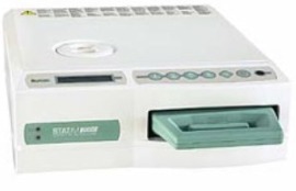
Цена:
255 000
255000
RUB
2029-12-31
руб.
Заказать
Кассетный автоклав STATIM 2000 (1,8 литров), (SciCan, Канада)
Автоклавы STATIM прошли тесты и испытания в ведущих медицинских университетах мира, имеют сертификат соответствия Госстандарта РФ и регистрационное удостоверение Минздрава РФ.
Области применения:
- Стоматология;
- Офтальмология;
- Зндоскопия;
- Гинекология.
Особенности:
- Малое время полной стерилизации (всего 6 минут при температуре 135 С) обеспечивает быстрое и экстренное автоклавирование.
- Наиболее бережное, по сравнению с другими автоклавами, отношение к дорогостоящему оборудованию (инструмент не окисляется, турбинные и эндонтические наконечники, алмазные боры служат дольше).
- Уникальная конструкция кассеты (12 часов инструмент остаётся стерильным), одновременно: стерильный лоток для
- инструмента, камера для стерилизации и компактный контейнер для хранения и переноски.
- Полная автоматизация процесса стерилизации обеспечивает наиболее удобную и простую эксплуатацию в различных режимах работы:
- режим стерилизации открытого инструментария – 3,5 минуты, 135оС;
- режим стерилизации закрытого инструментария – 10 минут, 135оС;
- режим бережной стерилизации (резина, пластик) – 15 минут, 121оС;
- режим максимальной загрузки неупакованного инструмента — 6 минут, 135оС;
- режим сушки и охлаждения – автоматически после каждого цикла.
- Высокая экономическая эффективность применения за счёт сокращения времени между приёмами пациентов и увеличения срока службы инструмента.
- Может быть укомплектован принтером.
Технические характеристики STATIM 2000:
|
Объем кассеты |
2 литра |
|
Размеры |
48 х 41.5 х 15 см |
|
Размеры кассеты |
28 х 18 х 3.5 см |
|
Ёмкость |
4 литра (дистиллированной воды) приблизительно на 40 циклов |
|
Вес без воды |
21 кг |
|
Питание |
220В, 60Гц, 1300 Вт |
|
Автоклав кассетный |
Технические характеристики: |
|
Уникальный номер реестровой записи: |
|
|
Реестровая запись |
|
|
Регистрационный номер медицинского изделия: |
МЗ РФ № 2003/295 |
|
Дата государственной регистрации медицинского изделия: |
13.03.2003 |
|
Срок действия регистрационного удостоверения: |
13.03.2013 |
|
Наименование медицинского изделия: |
Стерилизаторы кассетные STATIM |
|
Наименование организации-заявителя медицинского изделия: |
ЗАО «МТС» |
|
Место нахождения организации-заявителя медицинского |
|
|
Наименование организации-производителя медицинского |
SciCAN |
|
Место нахождения организации-производителя медицинского |
Канада |
|
Код Общероссийского классификатора продукции для |
|
|
Класс потенциального риска применения медицинского изделия |
|
|
Назначение медицинского изделия, установленное |
|
|
Вид медицинского изделия в соответствии с номенклатурной |
|
|
Адрес места производства или изготовления |
|
|
Сведения о взаимозаменяемых медицинских изделиях: |
Operator’s Manual for SciCan Statim 2000 Car Receiver, Dental equipment (2 pages)
Specifications:1385/1385547-statim_2000.pdf file (29 May 2023) |
Accompanying Data:
SciCan Statim 2000 Car Receiver, Dental equipment PDF Operator’s Manual (Updated: Monday 29th of May 2023 06:57:04 AM)
Rating: 4.5 (rated by 38 users)
Compatible devices: STATMATIC smart 2, HYDRIM C61w G4, SANAO 200 L, STATIS 1.1 ST, Quantim 16, STATIM G4, SALUS, hydrim c51w.
Recommended Documentation:
Text Version of Operator’s Manual
(Ocr-Read Summary of Contents of some pages of the SciCan Statim 2000 Document (Main Content), UPD: 29 May 2023)
-
1, SciCan Statim 2000 1. Unwrapped Cycle This cycle is used to sterilize light loads of solid metal instruments such as hand instruments, speculums, and forceps. To select the Unwrapped Cycle, press the Unwrapped Cycle button, then press the START button. 2. Wrapped Cycle This cycle is used to sterilize solid or hollow meta…
-
2, 1. Cycle Instruments non enveloppés Ce cycle sert à stériliser une petite quantité d’instruments en métal dur comme les instruments manuels, les spéculums et les forceps. Pour sélectionner le cycle Instruments non enveloppés, appuyez sur la touche « Instruments non enveloppés » puis sur la touche « …
-
SciCan Statim 2000 User Manual
-
SciCan Statim 2000 User Guide
-
SciCan Statim 2000 PDF Manual
-
SciCan Statim 2000 Owner’s Manuals
Recommended: M220, PEXUSB7LP, Proline-5000 3744


-
Nevadent NZAE 3.7 A1
ELEKTRISCHE ZAHNBÜRSTE BedienungsanleitungIAN 368330_2101ELECTRIC TOOTHBRUSH NZAE 3.7 A1 ΗΛΕΚΤΡΙΚΗ ΟΔΟΝΤΟΒΟΥΡΤΣΑΟδηүίες χρήσης ELECTRIC TOOTHBRUSHOperating instructions …
NZAE 3.7 A1 40
-
Durr Dental VistaScan Perio Plus
3 / 4EN Installation and configuration instructionsVistaScan Perio PlusOnly fully-qualified personnel may set-up, install or operate this appli-ance.Minimum requirementsImaging program DBSWIN or VistaEasy by Dürr DentalThird-party software on requestComputer system See «System requirements …
VistaScan Perio Plus 2
-
septodont DENTAPEN
FR 3EN 4ES 5DE 6IT 7PT 8NL 9PL 10EL 11BG 12CS 13DA 14ET 15FI 16HU 17LT 18LV 19RO 20SK 21SL 22SV 23HR 24 26FR Seringue électronique pour Anesthésie DentaireEN Powered Injector for Dental AnesthesiaES Inyector motorizado para a …
DENTAPEN 28
-
Kulzer Venus Diamond
Gebrauchsanweisung Universelles lichthärtendes Nano-Hybridkomposit, röntgenopakVenus Diamond ist ein radiopakes, lichthärtendes Nano-Universalkomposit. Anwendungsgebiet sind adhäsive, zahnfarbene Front- und Seitenzahnrestaurationen. Aufgrund der hervorra-genden Materialeigenschaften sind dauerhaf …
Venus Diamond 2
Operating Impressions, Questions and Answers:
![]()
STATIM 2000S/5000S
C A S S E T T E A U T O C L A V E ™
• Operator’s Manual
• Benutzerhandbuch
• Manuel de l’utilisateu
• Manuale per l’operatore
• Manual del Operador
STAT 2000S/5000S Operator’s Manual 95-108430 Rev 7.0.
CopyrightIM 2009 SciCan. All rights reserved.

Table of Contents
1.Introduction . . . . . . . . . . . . . . . . . . . . . . . 3
2.Important Information . . . . . . . . . . . . . . . 4
2.1 Disclaimers
2.2 Statim 2000S — Unit Overview
2.3 Statim 5000S — Unit Overview
3.Installation . . . . . . . . . . . . . . . . . . . . . . . . 7
3.1 Environmental Considerations
3.2 Unit Placement
3.3 Connecting the Waste Bottle
3.4 Filling the Reservoir
3.5 Priming the Statim Pump
3.6 Setting the Time and Date
3.7 Language Selection
3.8 Assigning Unit Identifier Number
3.9 Shipping the Unit
4.Instructions for Use . . . . . . . . . . . . . . . 11
4.1 Statim 2000S — Cassette
4.2 Statim 5000S — Cassette
4.3 Statim 5000S — STAT-DRI Plates
4.4 Preparing and Loading Instruments
4.5 Instrument Weight Table
4.6 Selecting a Cycle
4.7 Running a Cycle
4.8 Stopping a Cycle
|
STATIM Cassette Autoclave and Statim are registered trademarks and |
|
|
STAT-DRI and DriTec logos are trademarks of SciCan Ltd. All other trademarks |
|
|
referred to in this manual are the property of their respective owners. |
|
|
For all service and repair inquiries: |
|
|
In Canada |
1-800-870-7777 |
|
United States: |
1-800-572-1211 |
|
Germany: |
+49 (0) 821 56 74 56-0 |
|
International: |
(416) 446-4500 |
|
Email: |
techservice.ca@scican.com |
|
Manufactured by: |
|
|
SciCan |
|
|
1440 Don Mills Road, |
|
|
Toronto ON M3B 3P9 |
|
|
CANADA |
|
|
Phone: |
(416) 445-1600 |
|
Fax: |
(416) 445-2727 |
|
Toll free: |
1-800-667-7733 |
5.Maintenance . . . . . . . . . . . . . . . . . . . . . 20
5.1 Cleaning the Cassette
5.2 Cleaning the Water Reservoir Filter
5.3 Cleaning the Reservoir
5.4 Cleaning the Exterior Surfaces
5.5 Changing the Statim 2000S Air Filter
5.6 Changing the Bacteria Retentive Air Filters
5.7 Replacing the Cassette Seal
5.8 Maintaining Fluid Levels
5.9 Reading Water Quality
5.10 Preventative Maintenance Schedule
6.The Communication Port . . . . . . . . . . . 25
6.1 The RS232 Communication Port
6.2 Installing the Statim Data Logger
6.3 Installing Paper on the Internal Printer
6.4 Removing Internal Printer Paper Jams
6.5 Internal Printer Output Overview
7.Troubleshooting . . . . . . . . . . . . . . . . . . 35
8.Spare Parts List . . . . . . . . . . . . . . . . . . 39
9.Warranty . . . . . . . . . . . . . . . . . . . . . . . . 40
10.Test Protocol . . . . . . . . . . . . . . . . . . . 41
10.1 Type Test
11.Specifications . . . . . . . . . . . . . . . . . . . 43
11.1 Statim 2000S — Specifications
11.2 Statim 5000S — Specifications
EU Representative
SciCan GmbH
Kurzes Geländ 10
D-86156 Augsburg
GERMANY
Phone: +49 (0) 821 56 74 56-0
Fax: +49 (0) 821 56 74 56-99
SciCan Inc.
701 Technology Drive
Canonsburg, PA 15317
USA
Phone: +1 724 820 1600
Fax: +1 724 820 1479
Toll free: 1-888-632-6031
SciCan Medtech
Alpenstrasse
166300 Zug
SWITZERLAND
Phone: +41 (0) 41 727 7027
Fax: +41 (0) 41 727 702
Page 2

1. Introduction
|
Statim 5000S |
|
Statim 2000S |
Congratulations on your selection of the STATIM® Cassette Autoclave. We are confident that you have purchased the finest equipment of its type. The Statim is a compact, counter-top unit that features a number of sterilizing cycles designed to meet your needs and suitability for steam sterilization. The Statim “S” Cassette Autoclaves are fully compliant with EN13060.
The details of installing, operating and servicing your Statim are all contained within this operator’s manual. To ensure years of safe, trouble-free service please read these instructions before operating this unit and keep them for future reference. Operational, maintenance and replacement instructions should be followed for the product to perform as designed. Contents of this manual are subject to change without notice to reflect changes and improvements to the Statim product.
The Statim is suitable for the sterilization of dental and medical instruments designed
to withstand steam sterilization. The Statim has not been designed to sterilize liquids, cloth loads, biomedical waste or materials not compatible with steam sterilization.
The processing of such loads may result in incomplete sterilization and / or damage to the autoclave. For more information about instrument suitability for steam sterilization, consult the manufacturers’ reprocessing instructions.
Page 3

2. Important Information
2.1 Disclaimers
Use only steam-process distilled water in your Statim. Deionized, demineralized, or specially filtered water should not be used. Never use tap water.
Do not permit any person other than certified personnel to supply parts for, service or maintain your Statim. SciCan shall not be liable for incidental, special or consequential damages caused by any maintenance or services performed on the Statim by a third party, or for the use of equipment or parts manufactured by a third party, including lost profits, any commercial loss, economic loss, or loss arising from personal injury.
Never remove the cover of the unit and never insert objects through holes or openings in the cabinetry. Doing so may damage the unit and / or pose a hazard to the operator.
All elements of this book are common to both Statim 2000S and Statim 5000S except when noted.
IMPORTANT:
Follow local guidelines governing verification of the sterilization procedure.
Drying Performance
The Statim 2000S and 5000S have been designed to provide a complete sterilization solution for your unwrapped and wrapped instrument needs: rapid sterilization balanced with rapid drying, by using the SciCan Dri-Tec Drying Technology.
The Statim 2000S uses convection heat to dry instruments by utilizing the remaining heat in the system after the sterilization phase. Heat is captured and released in the cassette to rapidly dry a properly loaded Statim cassette.
The Statim 5000S uses heat generated by the sterilization phase which is absorbed by the drying plates. The heat is transferred from drying plates directly to the load resulting in accelerated, rapid drying of a properly loaded Statim cassette.
Please refer to this operator’s manual for instructions on the proper arrangement of instruments in the cassette and the use of Stat-Dri plates (Statim 5000S). By carefully following these directions on how to properly load the cassette chamber, rapid drying of the load will be achieved.
Page 4
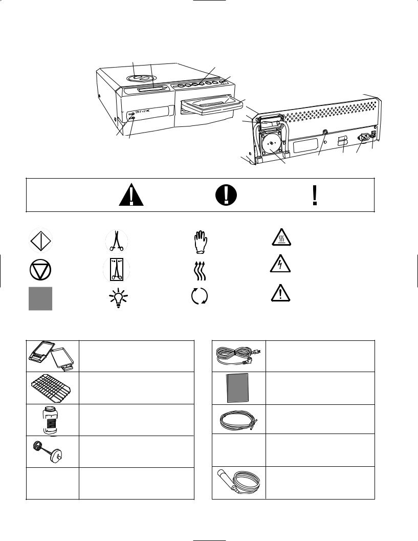
STOP button
Steam distilled water only
START button
|
2. |
Important Information Con’t. |
|||||||||||
|
2.2 Statim 2000S — Unit overview |
||||||||||||
|
■ level indicator |
■ |
4 |
Figure 1 |
|||||||||
|
1 |
3 |
■ |
||||||||||
|
■ keypad |
2 |
1 |
||||||||||
|
■ |
||||||||||||
|
2 |
■ |
|||||||||||
|
■ reservoir cap/ |
||||||||||||
|
3 |
||||||||||||
|
■ |
water filter |
12 |
||||||||||
|
LCD |
||||||||||||
|
■ |
||||||||||||
|
4 |
||||||||||||
|
■ |
power indicator |
|||||||||||
|
5 |
13 |
|||||||||||
|
■ active indicator |
||||||||||||
|
6 |
■ |
|||||||||||
|
■ power switch |
||||||||||||
|
7 |
■ |
5 |
||||||||||
|
■ power cable port |
||||||||||||
|
8 |
6 |
■ |
||||||||||
|
■ leveler feet |
||||||||||||
|
9 |
7 |
|||||||||||
|
9 |
14 8 |
|||||||||||
|
■ exhaust tube port |
■ cassette |
■ biological filter |
11 |
■ |
■ |
|||||||
|
■ |
■ ■ |
|||||||||||
|
10 |
12 |
13 |
■ |
10 |
||||||||
|
■ compressor |
■ |
RS232 port |
||||||||||
|
11 |
14 |
|||||||||||
|
The following symbols |
A potential hazard |
A situation which |
Important |
|||||||||
|
appear in the margins |
may lead to a |
|||||||||||
|
to the operator. |
information |
|||||||||||
|
of this book. |
mechanical failure. |
|||||||||||
The following symbols appear on the unit: UNWRAPPED cycles
WRAPPED cycles
Power Indicator LED
RUBBER /
PLASTIC cycles
Air dry only.
Active Indicator LED
Caution: Hot Surface and/or Hot Steam
Caution: Risk of electrical shock. Disconnect supply before servicing
Caution: Refer to manual for details
When you receive your Statim 2000S packing carton, the items listed below will be included.
If any of the items are missing, contact your dealer immediately so the situation can be corrected.
Cassette Tray and Lid
Unwrapped Instrument
Rack
Waste Bottle
Bottle Lid Fitting
Tube Mounting Hardware
Power Cord
Operator’s Manual
Exhaust Tube
Stat-Dri
P.C.D. + 20 SciCan
Sterilization Emulators
Page 5
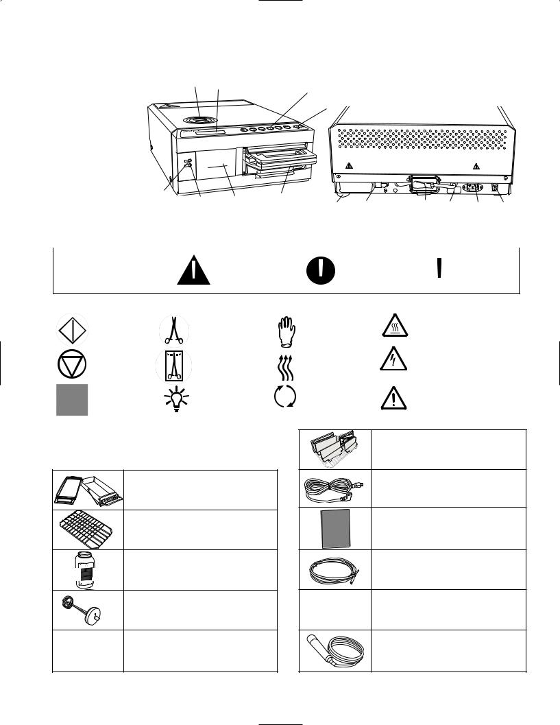
STOP button
Steam distilled water only
START button
|
2. |
Important Information Con’t. |
|||||||
|
■ |
2.3 Statim 5000S — Unit overview |
|||||||
|
level indicator |
3 |
|||||||
|
1 |
■ |
|||||||
|
■ keypad |
4 |
|||||||
|
■ |
||||||||
|
2 |
2 |
|||||||
|
■ |
reservoir cap/ |
|||||||
|
■ |
||||||||
|
3 |
1 |
|||||||
|
4 |
water filter |
|||||||
|
■ |
||||||||
|
■ LCD |
||||||||
|
■ |
power indicator |
|||||||
|
5 |
active indicator |
|||||||
|
■ |
||||||||
|
6 |
power switch |
|||||||
|
■ |
||||||||
|
7 |
power cable port |
|||||||
|
■ |
||||||||
|
8 |
||||||||
|
■ leveler feet |
6 |
|||||||
|
9 |
■ |
12 |
13 |
|||||
|
5 |
■ |
|||||||
|
■ exhaust tube port |
■ |
■ |
||||||
|
10 |
■ |
9 |
10 |
|||||
|
■ |
||||||||
|
■ biological filter |
||||||||
|
11 |
■ cassette |
■ |
RS232 port |
|||||
|
■ optional internal printer (not on all models) |
||||||||
|
12 |
13 |
14 |
Figure 2
■11 ■14 ■8 ■7
(not on all models)
|
The following symbols |
A potential hazard |
A situation which |
Important |
|||
|
appear in the margins |
may lead to a |
|||||
|
to the operator. |
information |
|||||
|
of this book. |
mechanical failure. |
|||||
The following symbols appear on the unit: UNWRAPPED cycles
WRAPPED cycles
Power
Indicator LED
When you receive your Statim 5000S packing carton, the items listed below will be included. If any of the items are missing, contact your dealer immediately so the situation can be corrected.
Cassette Tray and Lid
Unwrapped
Instrument Rack
Waste Bottle
Bottle Lid Fitting
Tube Mounting Hardware
RUBBER /
PLASTIC cycles
Air dry only.
Active Indicator LED
Caution: Hot Surface and/or Hot Steam
Caution: Risk of electrical shock. Disconnect supply before servicing
Caution: Refer to manual for details
Drying Enhancement Plates
Power Cord
Operator’s Manual
Exhaust Tube
Stat-Dri
P.C.D. + 20 SciCan
Sterilization Emulators
Page 6

3. Installation
3.1 Environmental Considerations
There are several factors that may affect the performance of your Statim.
Please review these factors, and select a suitable location in which to install the unit.
• Temperature and Humidity
Avoid installing your Statim in direct sunlight or close to a heat source (e.g. vents or radiators). The recommended operating temperatures are 15-25˚C with humidity of 25-70%.
• Spacing
The vents and openings on the Statim should remain uncovered and unobstructed. Leave a minimum of 50 mm between the top, sides and back of the unit and any
wall or partition.
• Venting
The Statim should be operated in a clean, dust free environment.
• Work Surface
The Statim should be placed on a flat, level, water-resistant surface.
Never install and operate the unit on a sloped surface.
• Electromagnetic Environment
The Statim has been tested and meets applicable standards for electromagnetic emissions. While the unit does not emit any radiation, it may itself be affected by other equipment which does. We recommend that the unit be kept away from potential sources of interference.
• Electrical Requirements
Use properly grounded and fused power sources with the same voltage rating as indicated on the label at the back of your Statim. Avoid multiple outlet receptacles. If using a surge suppressor power bar, plug in one Statim only.
3.2 Unit Placement
When placing the unit on a counter top, ensure the following:
|
• |
1 |
|
|
The level indicator bubble ■ on the front panel should be |
||
|
balanced in the front right quadrant of the target. |
This will |
|
|
ensure that the unit drains properly. Adjusting the three lev- |
||
|
eler feet will help you move the bubble if necessary. |
||
|
• The unit should be stable and all four feet should be secure- |
||
|
ly in contact with the counter surface. |
||
|
This will prevent the unit from moving freely. |
1 |
|
|
■ |
||
|
Figure 3 |
Page 7
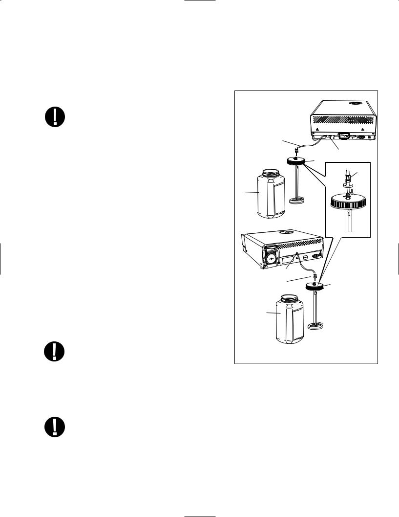
3. Installation Con’t.
3.3 Connecting the Waste Bottle
|
2 |
|||||
|
The waste bottle ■ is used to collect the wastewater after it has been converted |
|||||
|
to steam and then drained from the cassette. To connect the waste bottle to the |
|||||
|
Statim, follow these steps (see figure 4): |
|||||
|
3 |
4 |
5000S |
|||
|
1. Insert the exhaust ■ tube into the fitting |
■ |
||||
|
on the back of the unit and connect tightly. |
|||||
|
2. Cut the tube to length and slide the waste |
|||||
|
5 |
3 |
||||
|
■ |
|||||
|
bottle fitting ■ into place. |
|||||
|
4 |
|||||
|
3. Place the free end of the tube into the hole in |
■ |
||||
|
6 |
|||||
|
the lid of the waste bottle and hand-tighten |
■ |
||||
|
5 |
|||||
|
the fitting. Do not coil the exhaust tube. |
|||||
|
■ |
|||||
|
6 |
2 |
||||
|
4. Unscrew the lid and copper condenser coil ■ |
|||||
|
assembly from the waste bottle. The lid and |
■ |
||||
|
coil should come out together. |
|||||
|
5. Fill the waste bottle with water to the MIN line |
|||||
|
and replace the lid and copper condenser |
|||||
|
assembly. Empty the waste bottle often to |
|||||
|
avoid unpleasant odors and discoloration of |
|||||
|
the contents. (A low-level disinfectant, pre- |
2000S |
4 |
|||
|
pared according to the manufacturer’s |
■ |
||||
|
3 |
|||||
|
instructions, may be added to the waste |
■ |
6 |
|||
|
■ |
|||||
|
bottle to remedy this situation). As a mini- |
|||||
|
mum, empty the waste bottle each time |
|||||
|
you refill the reservoir. |
2 |
||||
|
■ |
|||||
|
6. Place the waste bottle near the unit. Store |
|||||
|
the bottle below the unit. The tube can be |
|||||
|
routed through a hole, (8 mm in diameter) |
Figure 4 |
||||
|
in the counter-top and secured with the |
|||||
|
provided nylon clamps. |
3.4 Filling the Statim Reservoir
When filling the reservoir, ensure you only use steam processed distilled water containing less than 5 ppm total dissolved solids (having conductivity of less than 10 µS / cm). The impurities and additives in other water sources will cause an error reading on the LCD. If you have a water conductivity meter (available from SciCan, order number 01-103139S) check each new water container before filling the reservoir. To fill the reservoir, follow these steps (see figure 5):
Page 8

3.5 Priming the Statim Pump
To prime the Statim pump, follow these steps:
3. Installation Con’t.
|
1. |
2 |
|
|
Remove the reservoir cap ■ |
2 |
|
|
■ |
||
|
2. |
Pour steam-process distilled water into |
|
|
the reservoir until almost full (a maxi- |
||
|
mum of 4L). Use a funnel to avoid |
||
|
spillage. |
||
|
3. |
Replace and secure the cap. |
Figure 5
1. Move the unit to the edge of the work surface. The front leveler feet should be approximately 12 mm from the edge.
2. Lift the front left corner of the unit upward and remove the drain tube ■3 from the clip located on the underside of the unit.
3. Pull the drain tube outward so the free end can be positioned over a water container. 4. Fill the reservoir with steam-process distilled water.
|
5. |
4 |
|||
|
Remove the plug ■ from the end of the drain tube and allow water to drain from the |
||||
|
tube into a container for 30 seconds. When the water flows in a steady stream, replace |
||||
|
the stopper. |
||||
|
4 |
||||
|
6. |
Lift the front left corner of the unit upward and reinsert |
■ |
||
|
the tube into the clip on the underside of the unit. |
3 |
|||
|
Push the excess length of tubing back into the space |
■ |
|||
|
provided. |
||||
|
Make sure the plug in the drain tube is secured. |
Figure 6 |
|||
|
3.6 Setting the Time and Date |
||||
|
To set the time and date, follow these steps and watch the blinking cursor on the LCD: |
||||
|
1. |
Power the Statim OFF. |
|||
|
2. |
Press and hold the UNWRAPPED cycle button. |
14:23 |
11/15/2006 |
|
|
HH:MM |
DD/MM/YYYY |
|||
|
3. |
While pressing the UNWRAPPED cycle button, |
Display when setting the Date / Time |
||
|
power the Statim ON. The LCD display reads: |
||||
4.Use the cycle buttons to select and change the selected field’s value. To increase a field’s value, press the UNWRAPPED cycle button. Hold the button down to increase the value.
5.To decrease the value, press the WRAPPED cycle button.
Page 9

3. Installation Con’t.
|
6. |
To select the next field, press the RUBBER AND PLASTICS cycle button. |
||||
|
7. |
To save changes and return to the regular operating mode, press the STOP button. |
||||
|
8. |
To quit without making changes, power the Statim OFF. |
||||
|
3.7 Language Selection |
|||||
|
The messages displayed on the LCD can be changed to a number of different languages. To |
|||||
|
change the current language selections, follow these steps: |
|||||
|
1. |
Turn the power switch at the back of the unit OFF. |
||||
|
2. |
Press and hold the WRAPPED cycle button. |
||||
|
ENGLISH |
|||||
|
3. |
While depressing the WRAPPED |
||||
|
cycle button, turn the power switch at |
|||||
|
Display when scrolling through languages |
|||||
|
the back of the unit to ON. |
|||||
|
4. |
Press the UNWRAPPED cycle button to scroll to the next language selection. |
||||
|
5. |
Press the WRAPPED cycle button to scroll to the previous language. |
||||
|
6. |
When the desired language is displayed, press the STOP button to save the selection |
||||
|
and return to the regular operating mode. |
|||||
|
3.8 Assigning Unit Identifier Number |
|||||
|
STATIM 2000 S2S2R601 |
|||||
|
1. |
Power the Statim OFF. |
||||
|
#323 |
|||||
|
2. |
Press and hold the RUBBER / PLASTIC cycle button. |
||||
|
Display when assigning unit number |
|||||
|
3. |
While pressing the RUBBER / PLASTIC cycle button, power the Statim ON. |
||||
|
4. |
Using the cycle buttons, select a maximum of 3 digits to be used as the unit’s identifier. The |
||||
|
UNWRAPPED button will increase the selected value and the WRAPPED cycle button will |
|||||
|
decrease it. Use the RUBBER / PLASTIC to move to the next digit. |
|||||
|
5. |
To save changes and return to the regular operating mode, press the STOP button. |
||||
|
3.9 Shipping the Unit |
|||||
|
Before you move the unit, you will need to drain the reservoir. To do so, follow these steps: |
|||||
|
1. |
Place a water container below the unit. |
||||
|
2. |
Using the drain tube (see section 3.5 Priming the Pump, Figure 6) empty the contents of |
||||
|
the reservoir into the water container. |
|||||
|
3. |
Remove any remaining water from the reservoir with a non-linting, absorbant towel. |
||||
|
4. |
Screw-in the three leveler feet found underneath the unit. |
||||
|
5. |
Repack the unit in the original packing materials and include all accessories originally |
||||
|
included with the unit. |
|||||
|
6. |
Specify heated and insured shipping. |
Page 10
![]()
4. Instructions For Use
|
4.1 Statim 2000S — Using the Cassette |
|||
|
When removing the cassette after a cycle, exercise caution as the metal areas will be hot |
|||
|
and the cassette may contain hot steam. |
|||
|
• |
To open the cassette: |
||
|
1. |
Hold the cassette handle with your thumbs facing inward on the cassette latch. |
||
|
2. |
Push downward on the cassette latch. |
cassette latch |
|
|
3. |
Raise the cassette lid upwards and disengage the |
||
|
hinge. |
|||
|
4. |
Rest the lid on its outer surface. |
||
|
• |
To close the cassette: |
Figure 7 |
|
|
1. |
Align the hinge tab on the cassette lid with |
||
|
the hinge slot on the rear of the bottom tray. |
|||
|
2. |
As you begin to close the lid, the hinge tab and slot will engage. |
• Inserting the cassette into the Statim 2000S:
1. Place the end of the cassette into the unit.
2. Gently push inward until you hear a “click” sound.
Never push the cassette into the Statim with force as the interior components could be damaged.
• Removing the cassette:
1. Grasp the handle with two hands and pull away from the unit.
2. Pull the cassette clear of the unit and set down on a firm surface.
|
• |
Disengaging the cassette |
||
|
When not in use, the cassette should be disengaged. To disengage the cassette, grasp the |
|||
|
handle and pull the cassette out until there is a 15 mm to 20 mm (1/2 |
to 3 /4«) gap between |
||
|
the front of the Statim 2000S and the cassette handle. |
|||
|
• |
STAT-DRI |
Treatment of the interior surfaces of the cassette with the Stat-Dri drying agent, provided with your unit, will enhance the drying process. (Replacement bottles are available from SciCan, order number 2OZPLUS, 8OZPLUST, 32OZPLUS).
Page. 11
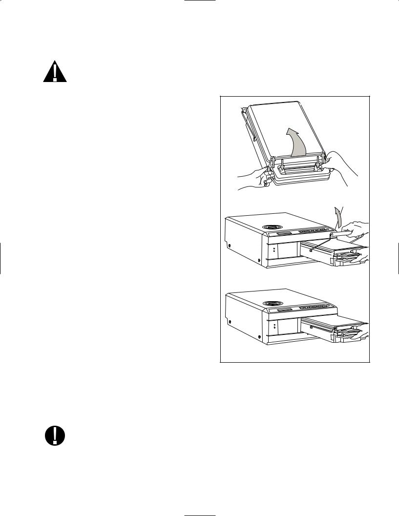
Figure 8
4. Instructions For Use Con’t.
|
4.2 Statim 5000S — Using the Cassette |
||||
|
When removing the cassette after a cycle, exercise caution as the metal areas will be hot |
||||
|
and the cassette may contain hot steam. |
||||
|
• |
To open the cassette: |
|||
|
1. |
1 |
|||
|
Push the carry handle ■ into the |
1 |
|||
|
open position. |
■ |
|||
|
2. |
Put your hands on either side of the cas- |
|||
|
sette handle. |
||||
|
3. |
Insert your forefingers in the slots and |
|||
|
place your thumbs on the thumb pads. |
||||
|
4. |
Press down with your thumbs and |
|||
|
pull up with your forefingers until |
||||
|
the lid opens. |
1 |
|||
|
■ |
||||
|
5. |
Raise the cassette lid and disengage |
|||
|
from the tray. Rest the lid on its |
||||
|
outer surface. |
||||
|
• |
To close the cassette: |
|||
|
1. |
Align the hinge tab on the lid with the |
|||
|
hinge slot on the tray. |
2.As you begin to close the lid, the hinge tab and slot will engage.
3. Place the carry handle into the closed position.
• Inserting the cassette into the Statim 5000S:
1. Hold the cassette handle in one hand and the carry handle in the other as shown in Figure 8.
2.Place the end of the cassette into the unit and drop the carry handle into its closed position.
3.Gently push the cassette inward until you hear a click sound.
Never push the cassette into the Statim with force as the interior components could be damaged.
Page 12
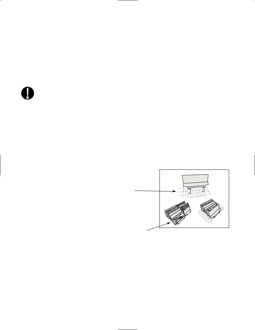
4. Instructions For Use Con’t.
• Removing the cassette:
1. Grasp the cassette handle with one hand and pull out from the unit.
2. As the cassette emerges from the unit, grasp the carry handle with your free hand and lift it upwards.
3. Pull the cassette clear from the unit and set down on a firm surface.
• Disengaging the cassette
When not in use, the cassette should be disengaged. To disengage the cassette, grasp the handle and pull the cassette out until there is a 15 mm to 20 mm (1/2 to 3 /4«) gap between the front of the Statim 5000S and the cassette handle.
4.3 Statim 5000S — STAT-DRI Plates
The Statim 5000S cassette uses STAT-DRI plates to enhance the drying process
for wrapped instruments. The adjustable plates are designed for the unwrapped instruments rack and eliminate the need for a separate wrapped instrument rack.
Up to ten plates can be arranged along the length of the rack. Each unit is shipped with five STAT-DRI plates. Additional plates may be ordered from SciCan (SciCan part number 01-103935).
To install and adjust a STAT-DRI plate, follow these steps:
1.Hold a plate over the desired position, tilted slightly forward with the tabs down.
2.Insert the tabs between the mesh of the unwrapped instrument rack.
3. Each tab has an elongated slot. Slide the plate until the wire is at the end of each slot.
4. Release the plate to the resting position.
5. Prepare and load instruments for sterilization.
4.4 Preparing and Loading Instruments
Before loading any instruments into the Statim, consult the manufacturer’s reprocessing instructions.
• Clean Instruments
Clean and rinse all instruments before loading them into the cassette. Disinfectant residues and solid debris may inhibit sterilization and damage the instruments, the cassette, and the Statim. Lubricated instruments must be wiped thoroughly and any excess lubricant should be removed before loading.
Page 13

4. Instructions For Use Con’t.
• Unwrapped Instruments
Arrange unwrapped instruments on the instrument rack in the tray so that they
do not touch one another. This ensures that steam reaches all surfaces and will promote drying.
Instruments must not be stacked or piled in the cassettes, as this will impede the sterilization process.
• Wrapped Instruments (single wraps)
Place the instruments into single layer autoclave bags according to the manufacturer’s instructions. Orient the instrument rack in the cassette to ensure that wrapped instruments rest approximately 6 mm / 0.25″ above the cassette base. Place the wrapped instruments on the rack and arrange them to avoid overlap. Ensure that all wrapped loads are dry before handling and /or storage to maintain sterility.
The use of cloth wraps in the Statim is not recommended.
SciCan recommends the use of paper / paper and plastic / paper autoclave bags manufactured in accordance to EN 868. Loosely pack instruments in the bags to allow steam penetration to all instrument surfaces.
The wrapped instrument rack for the Statim 5000S is designed to hold a maximum of
12 autoclave bags. Care must be taken to ensure that the combined weight of the loaded bags does not exceed 1.5 kg (3.3 lbs).
The unwrapped instrument rack fitted with a maximum of 10 Stat-Dri plates will hold 10 autoclave bags.
• Rubber and Plastic Instruments
The following materials can be sterilized in the Statim:
nylon, polycarbonate (Lexan™), polypropylene, PTFE (Teflon™), acetal (Delrin™), polysulfone (Udel™), polyetherimide (Ultem™), silicone rubber, and polyester.
When loading rubber and plastic instruments in the tray, leave a space between the instruments and the cassette walls. This ensures that steam reaches all surfaces, and will promote drying.
The following materials cannot be sterilized in the Statim:
polyethylene, ABS, styrene, cellulosics, PVC, Acrylic (Plexiglas™), PPO (Noryl™), latex, neoprene, and similar materials.
Use of these materials may lead to instrument or equipment damage. If you are unsure of your instrument’s material or construction, do not load into your Statim until you have checked with the instrument manufacturer.
Page 14

4. Instructions For Use Con’t.
• All Instruments
The Statim is NOT intended for sterilizing textiles, liquids or biomedical waste. Instruments will remain sterile after a successful cycle until the cassette is disengaged from the unit. Unwrapped instruments, once exposed to ambient or external conditions, cannot be maintained in a sterile state. If sterile storage is desired, wrap the instruments to be sterilized in autoclave bags, according to the instrument manufacturer’s instructions. Then allow the wrapped cycle to run until the air-dry phase is complete.
Best Practice: Allow instruments (wrapped or unwrapped) to dry completely prior to handling. Wrapped or pouched instruments must not touch each other to promote drying and enable effective sterilization.
SciCan recommends the final user carefully choose the most appropriate sterilization cycle according to the recommendations of their leading infection control authorities and local regulatory guidelines / recommendations.
• Routine Monitoring
Chemical process indicators suitable for steam sterilizers should be included in or on each package or load being sterilized. In addition, the weekly use of biological indicators, which allow you to ascertain whether the instruments have been exposed
to sterilization conditions, is recommended.
4.5 Instrument Weight Guide
|
Instrument |
Typical Instrument Weight |
|
|
Scissors |
30 g / 0.96 oz |
|
|
Dental scalers |
20 g / 0.64 oz |
|
|
Forceps |
15 g / 0.48 oz |
|
|
Dental handpiece |
40 to 60 g / 1.29 to 1.92 oz |
|
|
Wrapped instrument rack |
260 g / 8.35 oz |
|
|
Unwrapped instrument rack |
225 g / 7.23 oz |
|
|
Suction cannula |
10 g / 0.32 oz |
|
|
Plastic mouth mirror |
8 g / 0.25 oz |
|
|
Impression tray |
15 to 45 g / 0.48 to 1.45 oz |
|
|
Plastic x-ray positioning ring |
20 g / 0.64 oz |
NOTE: The above weights are to be used as reference only. For exact weights of your instruments, consult the manufacturer’s specifications.
Page 15
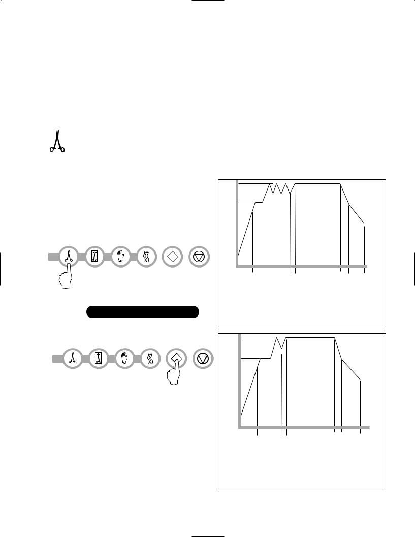
4. Instructions For Use Con’t.
4.6 Selecting a Cycle
The Statim 2000S and 5000S have seven sterilization cycles, each designed to sterilize using the parameters specified. Each cycle can be selected by pressing the UNWRAPPED, WRAPPED or RUBBER / PLASTIC cycle buttons.
The types of instruments, sterilization requirements and a graph depicting each cycle characteristics are described over the following pages.
1. Unwrapped Cycles
The Statim 2000S and 5000S feature two 134˚C type S and one 134˚C type N UNWRAPPED sterilization cycles. At the end of the cycle’s sterilization phase, air drying will commence for one hour.
Air-drying can be interrupted at any time by pressing the STOP button.
To select one of these cycles: Press the UNWRAPPED
cycle button to scroll through the available cycles.
|
HOLLOW UNWRAPPED (S) 134˚C / 3.5 min |
3.5 min / 18 min |
|||||
|
A |
B |
C |
D |
E |
F |
|
|
A 100˚C / 101 kPa |
D |
Sterilizing |
||||
|
HOLLOW UNWRAPPED (S) 134˚C / 18 min |
B |
3 purges (Conditioning) |
134˚C / 304 kPa — |
|||
|
peak at 133˚C / 295 kPa |
138˚C / 341 kPa |
|||||
|
SOLID UNWRAPPED (N) 134˚C / 3.5 min |
C |
Pressurizing |
F |
Air Drying |
||
|
vent to 115˚C / 169 kPa |
E |
Venting |
|
Once the desired cycle has been |
(Type S) |
||||
|
selected, press the START button. |
|||||
|
The unit memory remembers the last |
|||||
|
cycle run and then displays this first when |
|||||
|
the unit is powered on. |
|||||
|
A |
B |
C |
D |
E |
F |
|
3.5 min |
|
A 100˚C / 101 kPa |
D |
Sterilizing |
|
|
B |
1 purge (Conditioning) |
134˚C / 304 kPa — |
|
|
138˚C / 341 kPa |
|||
|
peak at 133˚C / 295 kPa |
|||
|
E |
Venting |
||
|
vent to 115˚C / 169 kPa |
|||
|
C |
Pressurizing |
F |
Air Drying |
|
(Type N) |
Page 16
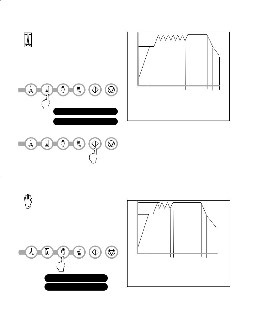
4. Instructions For Use Con’t.
2. Hollow Wrapped Cycles
The Statim 2000S and 5000S feature two WRAPPED 134˚C type S sterilization cycles.
To select one of these S Cycles: Press the WRAPPED button to scroll through the available cycles.
HOLLOW WRAPPED (S) 134˚C / 3.5 min HOLLOW WRAPPED (S) 134˚C / 18 min
|
A |
B |
C |
D |
E |
F |
|
3.5 min / |
|||||
|
18 min |
|||||
|
A 100˚C / 101 kPa |
D |
Sterilizing |
|||
|
B |
6 purges (Conditioning) |
134˚C / 304 kPa — |
|||
|
138˚C / 341 kPa |
|||||
|
peak at 133˚C / 295 kPa |
|||||
|
E |
Venting |
||||
|
vent to 115˚C / 169 kPa |
|||||
|
C |
Pressurizing |
F |
Air Drying |
Once the desired cycle has been selected, press the START button.
The unit remembers the last cycle run and then displays this first when the unit is powered on.
A Process Challenge Device (PCD) is available for validation of HOLLOW WRAPPED (S) 134˚C/3.5 min cycle.
3. Rubber and Plastics Cycle
The Statim 2000S and 5000S feature two 121˚C type S sterilization cycles.
To select one of these S Cycles: Press the RUBBER / PLASTIC button to scroll through the available cycles.
RUBBER / PLASTIC (S) 121˚C / 15 min
RUBBER / PLASTIC (S) 121˚C / 30 min
|
A |
B |
C |
D |
E |
F |
|
15 min / 30 min |
|
A 100˚C / 101 kPa |
D |
Sterilizing |
|
|
B |
3 purges (Conditioning) |
121˚C / 205 kPa — |
|
|
124˚C / 225 kPa |
|||
|
peak at 120˚C / 199 kPa |
|||
|
E |
Venting |
||
|
vent to 110˚C / 143 kPa |
|||
|
C |
Pressurizing |
F |
Air Drying |
Page 17

4. Instructions For Use Con’t.
Once the desired cycle has been selected, press the START button.
The unit remembers the last cycle run and then displays this first when the unit is powered on.
4. Air Dry Only Cycle
This is not a sterilization cycle.
The Air Dry Only Cycle starts automatically after each sterilizing cycle and runs for 60 minutes.
Air drying may be interrupted by pressing the STOP button. To ensure that the contents of the cassette are dry, the cycle should run for the full 60 minutes. Dryness is important for unwrapped instruments for corrosion prevention. For wrapped instruments, a dry wrap is required to maintain sterility.
If the STOP button is pressed during the air drying stage of the sterilization cycle, and the cassette has not been removed from the autoclave, the Air Dry Only cycle may be used to promote further drying. If the cassette has been removed from the autoclave, it may NOT be reinserted for the Air Dry Only cycle. If the cassette contains wrapped instruments and the wraps are not dry when the cassette is opened, the instruments must be handled in an aseptic manner for immediate use or resterilized.
To start, press the Air Dry Only Cycle button, then press the START button.
When started independently, this cycle will run for 1 hour.
Page 18

CONDITIONING 110˚C 143 kPa
14:23 11/15/2006 SELECT A CYCLE
4. Instructions For Use Con’t.
4.7 Running a Cycle
To operate each cycle, follow these steps and watch the LCD . 1. Turn the power switch ON
at the back of the unit to . The LCD display reads:
2.Press the appropriate cycle button on the keypad to scroll through the available cycles
|
The display will read either: |
||||
|
HOLLOW UNWRAPPED |
or |
HOLLOW WRAPPED (S) |
or |
|
|
(S) 134˚C / 3.5 min |
134˚C / 3.5 min |
|||
|
HOLLOW UNWRAPPED |
HOLLOW WRAPPED (S) |
|||
|
(S) 134˚C / 18 min |
134˚C / 18 min |
SOLID UNWRAPPED (N) 134˚C / 3.5 min
As the button is released the display reads:
Cycle you selected
PRESS START

RUBBER / PLASTIC (S) 121˚C / 15 min
RUBBER / PLASTIC (S) 121˚C / 30 min
The unit’s cycle counter is displayed at the start, after the start button is depressed.
Cycle you selected CYCLE NUMBER 000000
The amber indicator light comes on. To indicate that the cycle is in progress, the following messages are displayed as the cycle runs.
Cycle you selected WARMING UP
PRESSURIZING 125˚C 232 kPa
As the cycle is running, various sounds will be heard.
This is the normal functioning of the unit.
|
STERILIZING |
|
|
136.8˚C 330 kPa 3:29 |
VENTING |
|
108˚C 134 kPa |
Page 19

4. Instructions For Use Con’t.
The buzzing noise during the air drying stage is the compressor operating. The air drying phase of the cycle may be interrupted at any time by pressing the STOP button. The display will read:
PLEASE WAIT
CYCLE COMPLETE
When the automatic 60-minute air drying stage is finished the display reads:
REMOVE CASSETTE
CYCLE COMPLETE
If a sterilization cycle is successful the reminder tone sounds and the amber light flashes until the STOP button is pressed or the cassette is removed from the unit.
4.8 Stopping a Cycle
To stop a cycle press the STOP button. If the STOP button is pushed, the cassette is removed, or the unit detects a problem while operating, the cycle will stop and the amber active light will flash. Once a cycle has been stopped, the STOP button must be pressed before another cycle can be started. The display reads any of the following messages:
CYCLE FAULT xxx NOT STERILE or
CASSETTE REMOVED
NOT STERILE
If the display shows the message, CYCLE FAULT or NOT STERILE, the cassette contents are not sterile! See section 7. Troubleshooting for more information.
If the air drying stage of the cycle is interrupted, do not store wrapped instruments that were in the cassette unless they are dry.
Page 20
![]()
5. Maintenance
5.1 Cleaning the Cassette
Keeping the Statim cassette clean is good clinical practice and assists in the function of the unit. SciCan recommends that the interior surface be cleaned at least once a week. Use dishwashing soap or a mild detergent that does not contain chlorine. Scrub the inside of the cassette with a cleaning pad designed for use with Teflon™ coated surfaces. After scouring, rinse thoroughly with water to remove all traces of the detergent. Cleaning the inside of your cassette is very important if you regularly sterilize lubricated instruments. Coating the entire inside surface with STAT-DRI drying agent induces water to form an even coat on the inside surface, without beading. The water in contact with the hot cassette surfaces also evaporates much more efficiently. Spotting is minimized and instruments dry much better. STATDRI should be applied every 10 cycles, and after every cassette cleaning.
5.2 Cleaning the Water Reservoir Filter
This water reservoir filter should be cleaned at least once a week or when required. The filter can easily be removed and cleaned by placing the filter upside down under running water to wash away the particles until clean, and then placed back into the reservoir opening. If a replacement water reservoir filter is required, order part number 01-109300S.
5.3 Cleaning the Reservoir
Check the reservoir for dirt or particles. The reservoir may be cleaned by draining followed by cleaning and rinsing with steam process distilled water ONLY. Use of chemicals or cleaning agents is not reccommended and could cause the unit damage.
5.4 Cleaning the Exterior Surfaces
Use a soft cloth moistened with soap and water to clean all exterior surfaces. Do not use harsh cleaning chemicals or disinfectants.
|
5.5 Changing the Statim 2000S Air Filter |
|||||
|
The filter should be replaced every six months in order to maintain an adequate supply of |
|||||
|
clean air during the air drying cycle. |
|||||
|
To change the filter, follow these steps: |
2000S |
||||
|
1. |
Turn the power switch at the back of the unit OFF. |
||||
|
2. |
Remove and discard the old foam air filter |
4 |
|||
|
■ . |
|||||
|
3. |
4 |
||||
|
Install the new filter ■ (SciCan part no. 01-100207S). |
|||||
|
4. |
2 |
||||
|
Secure the filter plate ■ to the back of the compressor |
4 |
||||
|
1 |
|||||
|
■ |
|||||
|
using the screw ■ retained during |
2 |
||||
|
the disassembly procedure. |
|||||
|
■ |
|||||
|
1 |
|||||
|
■ |
Figure 10 |
||||
Page 21

5. Maintenance
5.6 Changing the Bacteria Retentive Air Filters
The filters should be replaced every six months or after 500 cycles to maintain an adequate supply of clean air during the air drying cycle.
To change the bacteria retentive air filter on the Statim 2000S and 5000S, follow these steps:
1. Power the Statim OFF.
|
2. |
1 |
|||||||
|
Disconnect tube A ■ from the bacteria |
2 |
2000S |
||||||
|
2 |
||||||||
|
■ |
3 |
|||||||
|
retentive filter |
■ |
3and remove the filter from |
||||||
|
■ |
||||||||
|
the filter bracket |
■ . As you remove the filter |
|||||||
|
from the bracket, note the orientation of the |
1 |
|||||||
|
arrow mark on the filter. |
■ |
|||||||
|
3. When the filter is free of the bracket, carefully discon- |
||||||||
|
4 |
||||||||
|
nect tube B ■ from the filter. |
4 |
|||||||
|
■ |
Figure 11 |
|||||||
|
4. Before installing the replacement |
||||||||
|
2 |
||||||||
|
bacteria retentive filter ■ (SciCan order |
5000S |
|||||||
|
no. 01-102119S) check that the arrow mark |
||||||||
|
on the filter matches the direction |
||||||||
|
of the arrow on the bracket. Push the left |
||||||||
|
4 |
2 |
|||||||
|
hand filter fitting into tube B ■ . |
1 |
|||||||
|
■ |
||||||||
|
■ |
||||||||
|
5. Gently press the replacement filter into |
||||||||
|
the filter bracket |
3 |
4 |
3 |
Figure 12 |
||||
|
■ . The arrow mark of |
||||||||
|
the filter should be facing out and pointing to |
■ |
■ |
||||||
|
the left. |
||||||||
|
6. |
1 |
|||||||
|
Re-connect tube A ■ to the right hand filter fitting. |
5.7 Replacing the Cassette Seal
To ensure optimum performance of your Statim cassette autoclave, change the
cassette seal every 500 cycles or every six months, whichever comes first. Replacement seals are available from SciCan (order number 01-100028S for Statim 2000S and 01101649S for Statim 5000S).
To change the cassette seal, follow these steps:
Place the cassette lid and the new seal on a clean work surface. Examine the position of the old seal in the cassette lid and arrange the new seal in the same orientation, next to the lid.
Page 22
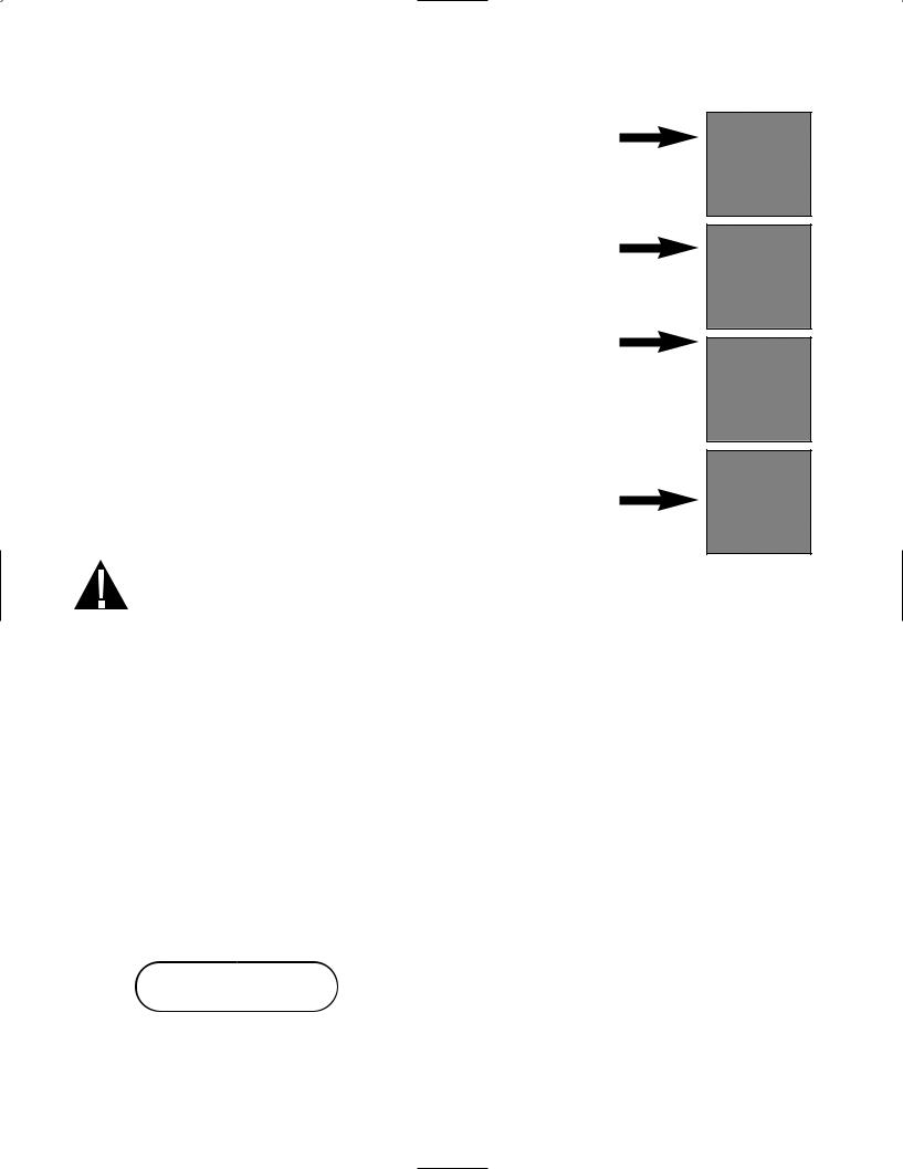
5. Maintenance con’t.
Remove the old seal and discard. Clean any residue out of the seal channel and flush out the channel with distilled water.
|
Lubricate the new seal with the liquid seal lubricant provided. |
|
|
Insert the rounded edge of the seal under the round lip of |
|
|
the lid. Align the holes in the new seal with the holes in the lid. |
|
|
NOTE: At every corner and at the holes in the lid, two square nibs |
|
|
should be visible. The nibs should fit flush with the lid’s outer surface. |
|
|
Ensure the seal is completely inserted. Feel around |
|
|
the periphery to ensure the seal is securely in place. |
|
|
NOTE: During a cycle, steam may appear between the lid |
|
|
and the tray. If this persists, remove the cassette and check |
|
|
that the seal is correctly installed. |
|
|
Figure 13 |
|
|
Be careful. The metal parts will be hot, and the cassette may contain hot steam. |
5.8 Maintaining Fluid Levels
Use only steam-process distilled water containing less than 5 ppm total dissolved
solids (having conductivity of less than 10 µS / cm) in the Statim. To fill the reservoir, remove the cap from the top of the unit and fill the reservoir. We recommend using
a funnel to minimize spills. Each time you refill the reservoir, empty the waste bottle
and refill with water to the MIN line. Empty the waste bottle often to avoid unpleasant odors and discoloration of the contents. (A low-level chlorine-free disinfectant,
prepared according to the manufacturer’s instructions, may be added to the waste bottle to remedy this situation).
|
5.9 Reading Water Quality |
|||
|
1. |
Power up unit while pressing the STOP button to access the User Setup menu. |
||
|
2. |
Using the UNWRAPPED and WRAPPED buttons, scroll to Water Quality and select it by |
||
|
pressing the RUBBER AND PLASTIC button. |
|||
|
>Water Quality |
CD=conductivity |
XX= micro S. value |
|
|
CD=XXuS / yyy / z.z ppm |
yyy= engineering value |
z.z= parts per million value |
|
|
l |
Page 23
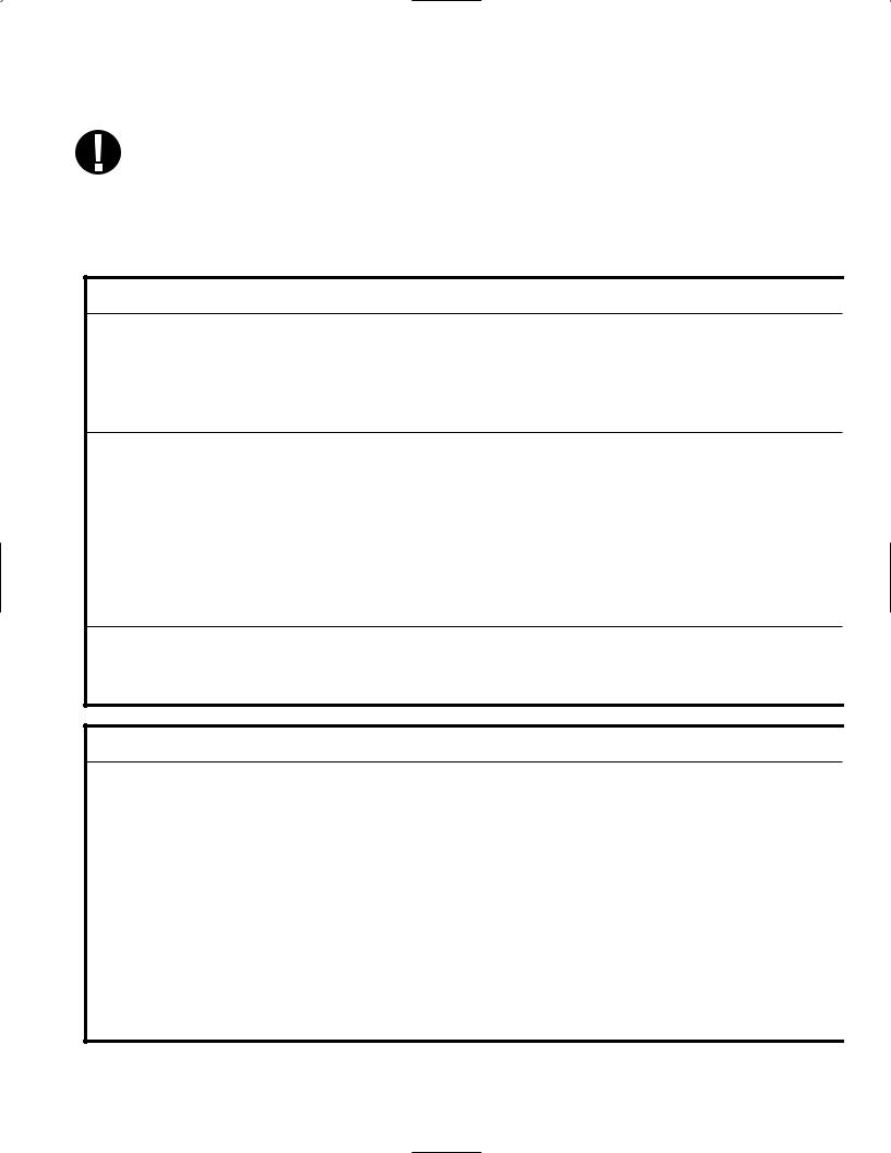
5. Maintenance con’t.
Daily
Weekly
Every 6 months
5.10 Preventative Maintenance Schedule
To ensure trouble-free performance, both the operator and the dealer must follow
a preventative maintenance schedule. NOTE: Please refer to your National, Regional, State or Safety laws for any additional reoccurring user testing that may be required.
The schedules below describe the necessary actions.
|
Operator |
|
|
Water Reservoir |
• Replace water as needed. |
|
• For opthalmic use, drain at the end of every workday, leave empty, and refill at the start |
|
|
of the next workday. |
|
|
Waste Bottle |
• Empty the waste bottle every time you refill the water reservoir. |
|
• Fill the bottle with water, up to the MIN line marking. |
|
|
Cassette |
• Wash the interior of the cassette with dishwashing soap or a mild detergent that does not |
|
contain chlorine. |
|
|
• Scrub the inside with a cleaning pad designed for use with Teflon™-coated surfaces. |
|
|
• After removing all traces of the detergent, treat interior surfaces of the cassette with |
|
|
the STAT-DRI™ Plus drying agent to enhance the drying process. Order more STAT- |
|
|
DRI™ Plus from SciCan quoting 2OZPLUS, 8OZPLUST, or 32OZPLUS. |
|
|
Biological and/or |
• Check the filter for dirt and moisture. Replace if dirty. Call for service if wet. |
|
Air Filter |
|
|
Water Filter |
• Check the water reservoir filter every week and clean if necessary. Replace only if necessary. |
|
Cassette Seal |
• Replace every 500 cycles or six months (whichever is first), or whenever necessary. |
|
Biological and/or |
• Replace every 500 cycles or six months (whichever is first). |
|
Air Filter |
|
Once a year
|
Technician |
|
|
Cassette |
• Check the tray, lid and seal for damage. Replace if necessary. |
|
Biological Filter |
• Inspect the biological filter for moisture. |
|
Solenoid Valve |
• Inspect the valve and clean if dirty. Replace the plunger if defective. |
|
Pump |
• Clean the filters, replace if dirty. |
|
Check Valve |
• Remove the exhaust tube from the back of the unit during the air drying phase. Check for |
|
air coming from the fitting. |
|
|
• Remove the air compressor tube from the check valve inlet while running a cycle. Make |
|
|
sure no steam is leaking from the valve. Replace if there are any leaks. |
|
|
Water Reservoir |
• Check the reservoir for dirt. Clean and rinse with steam process distilled water if necessary. |
|
Calibration |
• Calibrate the unit. |
Page 24

|
6. The Communication Port |
|||
|
6.1 The RS232 Communication Port |
|||
|
All Statim units that do not have an internal |
Printer |
||
|
printer will have an RS232 communication |
|||
|
port that will allow you to connect to an external |
|||
|
printer or to a SciCan Data Logger. For printing, |
|||
|
you will need to purchase a recommended printer |
|||
|
(see list below) from your local computer or electron- |
OR |
||
|
ics store. For data storage, you can |
|||
|
purchase SciCan’s USB Data Logger to record |
|||
|
and store cycle information onto a mass storage |
|||
|
device (MSD) such as a USB Flash Drive or SD |
Data |
||
|
memory card. |
Logger |
||
|
Printer Model |
End Of Line |
Serial Port |
Printer user ° |
|
CR/LF |
Bitrate |
character |
|
|
Epson |
|||
|
TM-U220D (C31C515603) |
CR/LF |
9600 |
248 [0xF8] |
|
Citizen |
|||
|
IDP-3110-40 RF 120B |
CR |
9600 |
N/A |
|
Star Micro |
|||
|
SP212FD42-120 |
CR |
9600 |
210 [0xd2] |
|
Star Micro |
|||
|
SP216FD41-120 |
CR/LF |
9600 |
210 [0xd2] |
|
Star Micro |
|||
|
SP512MD42-R |
CR/LF |
9600 |
210 [0xd2] |
|
SciCan Data Logger |
End Of Line |
Serial Port |
Printer user ° |
|
CR/LF |
Bitrate |
character |
|
|
For Mass Storage Device* |
N/A |
9600 |
32 [0xd2] |
*Due to a variety of software programs/viewers that can be used to view the data files stored on a mass storage device such as a USB memory stick, we recommend the above settings.
For your Statim to communicate to a specific device, you must enable this function through the User Setup menu. Follow the instructions in section 6.2 Installing the
SciCan Data Logger below to enable communication to either an external printer or the SciCan Data Logger.
Page 25

6. The Communication Port con’t.
6.2 Installing the SciCan Data Logger
SciCan’s USB Data Logger can record and store cycle information onto a mass storage device (MSD) such as a USB Flash Drive or SD memory card.
These instructions are for units with a 9-pin communication (RS232) port located at the back of the unit.
Follow the steps below before connecting the Data Logger.
User Mode
Time/Date Setup
Language Setup
Unit ID Setup
Water Quality
Last Printout
RS232
End Of Line CR/LF Serial Port Bitrate Printer user ° char Save and Exit
Exit
User Setup Menu
To install the SciCan Data logger, access the user setup menu by powering up the unit while pressing the STOP button.
Follow the instructions below to complete installation steps.
STEP 1
Selecting the USB Flash/MSD Option
1.Power up unit while pressing the STOP button to access the User Setup menu.
2.Using the UNWRAPPED and WRAPPED buttons, scroll to RS232 and select it by pressing the RUBBER AND PLASTIC button.
3.From the RS232 menu, use the UNWRAPPED and WRAPPED buttons to scroll down to the USB/FLASH MSD option and press the RUBBER AND PLASTIC button to select and return to the User Setup menu.
Page 26

6. The Communication Port con’t.
Setting the Serial Port Bitrate to 9600
1.From the User Setup menu, use the UNWRAPPED and WRAPPED buttons to scroll to the Serial Port Bitrate menu and select it using the RUBBER AND PLASTIC button.
2.From the Serial Port Bitrate menu, use the UNWRAPPED and WRAPPED buttons to scroll down to 9600 and press the RUBBER AND PLASTIC button to select and return to the User Setup menu.
Setting the Printer user Character; (example: 134°C)
|
Printer user ° char |
32 [0x20] |
1.From the User Setup menu, use the UNWRAPPED and WRAPPED buttons to scroll to the Printer user ° char menu and select it using the RUBBER AND PLASTIC button.
2.From the Printer user ° char menu, using the UNWRAPPED button to increase the displayed value by one, and the WRAPPED button to increase that value by ten, enter the value 32 [0x20] and press the RUBBER AND PLASTIC button to accept and return to the User Setup menu.
Save and Exit
 Save and Exit
A Save and Exit must be performed after the above settings are completed. If this is not done, the information will revert to its prior settings.
1.From the User Setup menu, use the UNWRAPPED and WRAPPED buttons to scroll to Save and Exit.
2.Select it by pressing the RUBBER AND PLASTIC button.
The LCD will display time and date information and a sequence of messages:
HH:MM DD/MM/YYYY
“MSD NOT DETECTED”/”INSERT MSD/FLASH”/”SELECT A CYCLE”
Page 27

6. The Communication Port con’t.
Step 2
Selecting the Time and Date
 Time/Date
  HH:MM DD/MM/YYYY
Note: If the time and date were set according to section 3.6, this does not have to be performed again.
1. Power up unit while pressing the STOP button to access the User Setup menu.
2. Using UNWRAPPED and WRAPPED buttons, scroll to Time/Date Setup and press the RUBBER AND PLASTIC button to select it.
3. From the Time/Date Setup menu, set the time and date using the UNWRAPPED and WRAPPED buttons to change the displayed values and the RUBBER AND PLASTIC button to select. Press the STOP button when completed.
Step 3
Setting Unit ID
|
Unit ID |
001 |
|||||
|
Note: If the unit ID |
was set according to section 3.8, this does not have to be |
|||||
|
performed again. |
||||||
|
1. |
Power up unit while pressing the STOP button to access the User Setup menu. |
|||||
|
2. |
Using the UNWRAPPED and WRAPPED buttons, scroll to the Unit ID Setup and press |
|||||
|
the RUBBER AND PLASTIC button to select it. |
||||||
|
3. |
From the Setup Unit ID menu, use the UNWRAPPED and WRAPPED buttons to change |
|||||
|
the displayed values and the RUBBER AND PLASTIC button to select and move to the |
||||||
|
next digit. Press the STOP button when completed. |
|
Step 4 |
|||
|
Connecting the SciCan Data Logger |
|||
|
1. |
Ensure that both the Statim unit and the SciCan Data Logger are off. |
||
|
2. |
Connect the SciCan Data Logger to the Statim unit by using the serial cable. |
||
|
3. |
Power up the SciCan Data Logger |
||
|
HH:MM DD/MM/YYYY |
|||
|
4. |
Power up the Statim unit. |
||
|
“MSD NOT DETECTED”/”INSERT |
|||
|
5. |
The LCD will display the following |
||
|
MSD/FLASH”/”SELECT A CYCLE” |
|||
|
sequence of messages: |
|||
|
6. |
Insert USB Flash Drive or SD memory card |
HH:MM DD/MM/YYYY |
|
|
7. |
After a few seconds the LCD will display |
USB/FLASH DETECTED/SAFELY |
|
|
the following sequence of messages: |
REMOVE MSD/SELECT A CYCLE |
||
Page 28

6. The Communication Port con’t.
6.3 Installing Paper on the Internal Printer
Use only paper approved for use with the optional internal printer on the Statim 5000S. The use of any other paper will damage the printer and will void the warranty. Thermal paper is available from SciCan (SciCan order no. 01-101657S).
Do not operate the printer without paper. If you run out of thermal paper, or if you do not wish to use the printer, turn it OFF.
Never pull the paper backwards through the printer. This will damage the printer mechanism.
To install the paper into the printer, follow these steps:
1.Power the Statim 5000S ON.
2.Open the printer door ■1 by pushing on the top half of the door.
3.Power the printer ON.
4.Unroll some paper from the thermal paper roll ■3 and trim the corners using the paper cutting template included with each box.
5.Move the paper roll arm ■4 into the loading position. Place the paper roll ■3 on the arm so the paper strip feeds from the top of the roll and then carefully insert
it into the paper feed slot ■5 until it stops.
If the paper does not feed from the top, the heat sensitive side of the paper will not be in contact with the print head and the printer will not print.
6.With one hand, continue to gently feed the paper strip into the paper feed slot. With the other hand, press the paper advance button until the paper feeds by itself.
Keep the paper straight when feeding it into the printer or it may jam. Do not force the paper into the slot! If the paper will not feed into the slot, pre-cut the end of the roll again and reload the paper.
Page 29

, follow these
6.The Communication Port con’t.
7.Continue to press the paper advance button ■6 until the paper feeds through the paper exit slot on the front of the printer. Then, move the paper roll ■3 and arm into the operating position and close the printer door ■1 . The printer is now ready to operate.
When you see a red line on one side of the paper, it is time to replace the roll.
If a paper jam occurs, and the paper cannot be removed by pressing the paper advance button ■6 , do not pull the paper backwards through the printer.
Never put a utensil or tool into the paper exit slot. For full instructions on how to remove paper jams, see section 6.4 Removing Internal Printer Paper Jams.
To replace the paper roll ■3 steps:
1.With scissors, cut the paper between the roll and the paper feed slot ■5 .
2.Remove the roll from the arm and discard the unused portion.
3.Press the paper advance button ■6 to feed
the paper that remains in the printer out of the slot at the front of the printer.
4.Install the new thermal paper roll by following the instructions described in this section.
■5 ■2
■4 ■3 ■1
■4
■6
Figure 15.1
■5 ■2
■6
■3 Figure 15.2
Page 30
![]()
6. The Communication Port con’t.
|
6.4 Removing Internal Printer Paper Jams |
||||
|
If paper jams in the printer and cannot be removed |
||||
|
by pressing the paper advance button ■, the print- |
||||
|
6 |
7 |
|||
|
er must be disassembled. Do not pull the paper |
■ |
|||
|
backwards through the printer and never put uten- |
||||
|
sils or tools into the paper exit slot. |
8 |
|||
|
■ |
||||
|
When paper is jammed in the printer, follow |
||||
|
these steps to remove the jam: |
||||
|
1. Power the Statim 5000S OFF and unplug the |
9 |
■ |
||
|
unit. |
■ |
|||
|
15 |
||||
|
2. Using scissors, cut the paper between the |
14 |
|||
|
roll and the paper feed slot ■. |
||||
|
5 |
13 |
■ |
||
|
3. Remove the paper roll ■ from the paper |
||||
|
3 |
■ |
■ |
||
|
roll arm ■ and leave the arm in the |
||||
|
4 |
11 |
|||
|
loading position. |
||||
|
4. Using a #1 Phillips screwdriver, remove the |
10 |
|||
|
■ |
||||
|
three screws ■ from the printer cover ■ and |
1 |
4 |
||
|
■ |
||||
|
7 |
8 |
■ |
||
|
remove the cover. |
10 |
|||
|
5. Note the orientation of the exposed printed |
■ |
|||
|
■ |
Figure 16 |
|||
|
wiring board and the paper roll arm |
■assem- |
|||
|
4 |
12 |
|||
|
bled on the printer door ■. |
||||
|
1 |
6.Gently lift the printed wiring board upwards and away from the printer door. Exercise care while handling the board. The printer is integral to the wiring board. Do not place strain on the connections of the ribbon cable soldered to the board. Do not remove the connector of the flexible cable from the connector header on the board. The paper drive mechanism on the underside of the wiring board is now exposed.
7.Using a pair of tweezers or fine needle-nosed pliers, carefully remove the paper from the mechanism.
When the paper is removed, reassemble the printer:
1.Carefully snap the paper roll holder, in the loading position, back into the clips on the printer door ■1 .
Page 31

6. The Communication Port con’t.
2. Place the printed wiring board back into position on the printer door. Note the alignment of the mounting holes ■9 in the wiring board and the mounting bosses ■13 on the printer door. The black plastic printer body rests between the locating ribs ■10 on the inside of the printer door.
3.Ensure that the flexible cables ■11 , ■14 are not pinched between the printer door and the wiring board.
4.Place the printer cover on the printer door. Ensure that the flexible cables are not pinched between the cover and the door. The power button and the paper advance button must protrude through the openings in the cover and operate freely.
5.Using a #1 Phillips screwdriver, secure the printer cover to the printer door with
the three screws retained during the disassembly procedure. Do not over-tighten these screws.
6.Plug your Statim 2000S / 5000S into the wall receptacle. Reconnect the printer if it was previously disconnected. Turn the power switch to the ON position.
7.Press the printer power button to the ON position. Load paper into the printer following the procedures in section 7.3 Installing Paper on the Internal Printer.
Page 32

6. The Communication Port con’t.
6.5 Cycle Printout Overview
1. Model: STATIM 2000 software: S2S2R410
2. Unit Identifier: autoclave has been set up as number 323
3. Cycle counter: the number of cycles having been run on the unit = 9
4. Time / Date: 1:38 pm 14th April, 2003
5. Cycle Name: SOLID UNWRAPPED (N)
6. Cycle Name cont’d – parameters: 134˚C /
3.5 min – 1P
7. Cycle clock: starting at 0:00
8. Warm up complete: start of the conditioning phase is 2:07 (see cycle graph – ‘A’ phase complete, start of ‘B’ phase)
9. Peek Temp. / Press. & Time of conditioning purge: for each purge (number of lines based on cycle selection – this is a one purge cycle – activity within ‘B’ phase )
10. Lowest Temp. / Press. & Time of conditioning purge: for each purge (number of lines based on cycle selection – this is a one purge cycle – activity within ‘B’ phase )
1.
2.
3.
4.
5.
6.
7.
8.
9.
10.
11.
12.
13.
14.
15.
16.
17.
18.
19.
20.
21.
22.
23.
Page 33

6.The Communication Port con’t.
11.Start Time of Pressurization: 3:21(start of ‘C’ phase)
12.Start Time of Sterilization: 4:12 (start of ‘D’ phase)
13.Temp. / Press. & Time at start of sterilization (‘D’ phase)
14.Min. Temp. / Press during the sterilization phase (lower limits of ‘D’ phase)
15.135.1˚C 308 kPa
16.Max. Temp. / Press during the sterilization phase (upper limits of ‘D’ phase)
17.136.7˚C 323 kPa
18.Temp. / Press. & Time of end of sterilization phase (end of ‘D’ phase)
19.Time Venting started: 7:43 (start of ‘E’ phase)
20.Sterilization was successfully completed
21.Time Air Drying started: 8:07 (start of ‘F’ phase)
22.Cycle was stopped by user
23.Drying cycle aborted prior to completion, load may not be dry
Page 34

7. Troubleshooting
|
Problem |
Solution |
||
|
Unit does not power ON. |
Check that the unit is plugged into a properly |
||
|
grounded outlet and that the power cord is firmly |
|||
|
seated at the rear of the machine. |
|||
|
Try another circuit. Power unit OFF for 10 seconds |
|||
|
and then power ON again. |
|||
|
Check the condition of the line circuit |
|||
|
breaker or fuse. |
|||
|
There is water under the machine. |
Check that water was not spilled when refilling the |
||
|
reservoir. Make sure the plug in the exhaust tube is |
|||
|
secured. Remove and reinsert the cassette . |
|||
|
Attempt another cycle. |
|||
|
Be careful. The metal parts will be hot, and the cas- |
|||
|
sette will contain hot steam. |
|||
|
The cassette is leaking. If water drips from the under- |
|||
|
side of the unit during operation, check the cassette |
|||
|
seal for misalignment or damage and replace the seal |
|||
|
if required. |
|||
|
Be careful. The metal parts will be hot, and the cas- |
|||
|
sette will contain hot steam. |
|||
|
Attempt another cycle. If it still leaks attempt another |
|||
|
cycle using a different cassette if possible. |
|||
|
If the leak persists, turn the unit OFF, remove and |
|||
|
unload the cassette, unplug the unit, and call |
|||
|
your dealer. |
|||
|
Instruments do not dry. |
Best drying occurs when the cycle continues to com- |
||
|
pletion. Allow the cycle to finish. Make sure the instru- |
|||
|
ments are loaded correctly in the cassette. Refer to |
|||
|
section 4.4 Preparing and Loading Instruments. |
|||
|
Check the unit leveling. |
|||
|
Clean the inside of the cassette and treat with Stat-Dri |
|||
|
drying agent. Refer to section 5.1 Cleaning the |
|||
|
Cassette. Examine the exhaust tube (tube to the |
|||
|
waste bottle) for kinks. |
|||
Page 35

7. Troubleshooting con’t.
|
If kinked, straighten the tube. If the tube cannot be |
|||
|
straightened, remove it from the push-in fitting |
|||
|
attached to the Statim. Depress the collar on the fit- |
|||
|
ting and with the other hand pull firmly on the tube. |
|||
|
Once the tube is free of the fitting, cut the damaged |
|||
|
section of tubing away using a sharp instrument. Be |
|||
|
sure that you leave enough tube to reach the unit |
|||
|
when you re-attach the tube to the exhaust fitting. If |
|||
|
the tube is too short to remove a section, contact your |
|||
|
SciCan dealer fora replacement. |
|||
|
Make sure the compressor is working. To check, |
|||
|
remove the exhaust tube from the waste bottle. |
|||
|
Start the Air Drying Only Cycle, and place the free |
|||
|
end into a glass of water. If there is not a strong, |
|||
|
steady flow of bubbles, the compressor is not |
|||
|
functioning properly. Contact your SciCan dealer. |
|||
|
Cycle interrupted — NOT STERILE, |
Wait a few minutes and attempt another cycle before |
||
|
Cycle aborted — NOT STERILE and |
proceeding to the next solution. Remove the cas- |
||
|
CYCLE FAULT messages. |
sette. Be careful. The metal parts will be hot and the |
||
|
cassette will contain hot steam. Inspect the cassette |
|||
|
to ensure that the holes in the back of the seal are |
|||
|
perfectly aligned, and that the flexible lip of the seal is |
|||
|
completely free. Check the exhaust tube for kinks or |
|||
|
obstructions. If kinked, straighten the tube. If the |
|||
|
tube cannot be straightened, remove it from the push- |
|||
|
in fitting attached to the Statim. Depress the collar on |
|||
|
the fitting and, with the other hand pull firmly on the |
|||
|
tube. Once the tube is free of the fitting, cut the dam- |
|||
|
aged section of tubing away using a sharp instrument. |
|||
|
Be sure that you leave enough tube to reach the unit |
|||
|
when you re-attach the tube to the exhaust fitting. If |
|||
|
the tube is too short to remove a section, contact your |
|||
|
SciCan dealer for a replacement. |
|||
|
Check that the Statim has not inadvertently been |
|||
|
exposed to any electrical interference. |
|||
|
Refer to the Installation section dealing with |
|||
|
Environmental Considerations. (Section 3.1) |
|||
|
Try running another cycle. If the problem persists, |
|||
|
record the cycle fault message number and contact |
|||
|
your dealer. |
|||
Page 36

7. Troubleshooting con’t.
|
Excessive steam issuing from the front |
Remove and reinsert the cassette. Attempt another |
|||
|
of the machine. |
cycle. Remove and check the cassette seal for mis- |
|||
|
alignment or damage. Replace the seal if required. |
||||
|
Be careful as the metal parts will be hot and the cas- |
||||
|
sette will contain hot steam. |
||||
|
If the leak persists, turn the unit OFF, remove and |
||||
|
unload the cassette and contact your SciCan dealer. |
||||
|
Message WATER QUALITY IS NOT ACCEPT- |
You have used water which is not steam-process dis- |
|||
|
ABLE. Machine will not start. |
tilled or is improperly distilled. |
|||
|
Empty the reservoir and refill with steam-process dis- |
||||
|
tilled water containing less than 5 ppm total disolved |
||||
|
solids (having conductivity of less than 10 µS / cm). |
||||
|
If you have the water conductivity meter, check the |
||||
|
quality of the water before refilling the reservoir. |
||||
|
Refer to the steps described in section 3.9 Shipping |
||||
|
the Unit to empty the reservoir. |
||||
|
Message REFILL RESERVOIR, |
The level of the water in the reservoir is low. Refill the |
|||
|
Machine will not start. |
reservoir. Refer to the steps described in section 3.4 |
|||
|
Filling the Reservoir. |
||||
|
Message PRINTER FAULT displayed on |
Check for a paper jam. If the paper is jammed, follow |
|||
|
LCD Printer is not printing. |
the paper removal procedures outlined in section 6.4. |
|||
|
Power unit OFF for 10 seconds and then power |
||||
|
ON again. If the paper is still jammed, follow the dis- |
||||
|
assembly procedures outlined in section 6.4 |
||||
|
Removing Paper Jams. |
||||
|
The printer does not work. |
Make sure that the printer cable is connected securely |
|||
|
with the connector on the back of the Statim |
||||
|
and the |
Statprinter. Make sure that the printer is pow- |
|||
|
ered ON. Power unit OFF for 10 seconds and |
||||
|
then power ON again. |
||||
|
The printer appears to work, but nothing is |
Ensure that the paper is loaded properly (refer to sec- |
|||
|
printed on the paper. |
tion 6.3 Installing Paper on the Internal Printer). Check |
|||
|
to see that the paper leaves the paper roll from the top |
||||
|
of the roll. This means that the treated surface of the |
||||
|
coated thermal paper will be in contact with the thermal |
||||
|
print head. |
||||
|
Time and date are incorrect. |
The time and date have not been set. See section |
|||
|
3.6 |
Setting the Time and Date. |
|||
Page 37

7. Troubleshooting con’t.
|
Message MSD NOT CONNECTED <> |
Check the serial cable connection. |
|
INSERT MSD/FLASH |
Check the power connection. |
|
Ensure the lower red LED is lit. |
|
|
Check that the Mass Storage Device is properly |
|
|
inserted. |
|
|
Repeat the instructions for Installing the SciCan |
|
|
Data Logger on your Statim. |
|
|
Message MSD/FLASH FULL <> |
The MSD is full. Export the data. |
|
REPLACE MSD |
|
|
Message Missing lines of |
Refer to the STATIM screen to confirm successful |
|
Data on MSD/FLASH |
sterilization. |
|
Reset the Data Logger by unplugging its power, dis- |
|
|
connecting the MSD and waiting 10 seconds. Then |
|
|
re-connect the power adapter and insert the MSD into |
|
|
the Data Logger. |
|
|
If the problem persists, contact the SciCan Service |
|
|
Center. |
|
|
Message: The file or directory in the |
Refer to the STATIM screen to confirm successful |
|
MSD is corrupted or unreadable. |
sterilization. |
|
The MSD may have been unplugged while data was |
|
|
being written to it. The MSD should not be unplugged |
|
|
until after “SAFELY REMOVE MSD <> MSD/FLASH |
|
|
DETECTED” is displayed. |
|
|
The corrupted files or directories may be lost. |
|
|
Reformat the MSD on your computer. |
|
Page 38

8. Spare Parts List
|
01-100204S |
Exhaust Tube |
|
01-100724S |
Condenser Bottle w / o |
|
Condenser |
|
|
01-100735S |
Waste Water Bottle Fitting |
|
01-100780S |
Bumper |
|
01-100782S |
Push-In Fitting (2000S) |
|
01-100812S |
Condenser Bottle |
|
01-100834S |
Cassette Lid (2000S) |
|
01-101649S |
Cassette Seal (5000S) |
|
01-101657S |
Thermal Paper (Box of 10 rolls) |
|
01-101658S |
Cassette Handles |
|
01-101709S |
Mesh Rack (5000S) |
|
01-101755S |
Push-In Fitting (5000S) |
|
01-101757S |
Cassette Lid w / Box (5000S) |
|
01-101766S |
Power Cord UK |
|
01-101768S |
Power Cord Switzerland |
|
01-101769S |
Power Cord Italy |
|
01-101779S |
Power Cord Europe |
|
01-106030S |
Cassette Lid Handle (2000S) |
|
01-106071S |
Extended Cassette Lid |
|
Handle (5000S) |
|
|
01-104093S |
Exhaust Tube 3 m long |
|
01-101783S |
Reservoir Cap and Filter |
|
01-101970S |
Data Cable (5000S) |
|
01-102119S |
Filter Biological |
|
01-103139S |
Conductivity Meter |
|
01-103475S |
Tray (2000S) |
|
01-103557S |
Power Cord Repl. Denmark (det.) |
|
01-103865S |
Seal Lubricant |
|
01-103945S |
Rack-Tray Unwrapped |
|
Instr. Kit (2000S) |
|
|
01-104343S |
Plug — Drain Tubing (5000S) |
|
01-104472S |
Extended Cassette Handles |
|
(5000S) |
|
|
01-104696S |
Handpiece Adapter |
|
01-104697S |
Adapter Cassette Seal (2000S) |
|
01-104698S |
Adapter Cassette Seal (5000S) |
|
01-104699S |
Seal Insert |
|
01-100207S |
Compressor Filter (2000S) |
|
01-104700S |
Adapter Cassette O-Ring Kit |
|
01-104702S |
Adapter Cassette Lid (2000S) |
|
01-104704S |
Adapter Cassette Lid (5000S) |
|
01-104786S |
Instrument Holder — 4 mm |
|
(5000S) |
|
|
01-100028S |
Cassette Seal (2000S) |
|
01-106438S |
Cassette Lid, Extended (2000S) |
|
01-108340S |
Statim PCD – spare parts |
|
01-109300S |
Water Reservoir Filter Kit |
|
ACCESSORIES |
|
|
01-100008A |
Kit Cassette Final (2000S) |
|
01-100271A |
Kit Tray Cassette w / Mesh |
|
(2000S) |
|
|
01-101613S |
Cassette Complete (5000S) |
|
01-101614S |
Tray Complete (5000S) with Box |
|
01-103923 |
Condenser Additional Bottle |
|
01-103935 |
STATDRI Plates (5000S) |
|
01-104104 |
Extended Length Cassette |
|
(5000S) |
|
|
01-104499 |
Extended Cassette Instrument |
|
Rack (5000S) |
|
|
01-104701 |
Adapter Cassette (2000S) |
|
01-104703 |
Adapter Cassette (5000S) |
|
01-106101 |
Handpiece Adapter Kit (2000S) |
|
01-106102 |
Handpiece Adapter Kit (5000S) |
|
01-106653 |
Mesh Tray (2000S) |
|
01-210000 |
Kit Printer (5000S) |
|
01-106325 |
Container Endoscope |
|
Complete (5000S) |
|
|
2OZPLUS |
STAT-dri 2 oz. |
|
8OZPLUST |
STAT-dri 8 oz. |
|
32OZPLUS |
STAT-dri 32 oz. |
|
99-108332 |
Chemical Emulator |
|
134˚C/3.5 min |
|
|
01-108341 |
Statim PCD Final Assembly Kit |
Page 39

9. Warranty
Limited Warranty
For a period of one year, SciCan guarantees that the Statim 2000S / 5000S, when manufactured by SciCan in new and unused condition, will not fail during normal service due to defects in material and workmanship that are not due to apparent abuse, misuse, or accident.
The one year warranty will cover the performance of all components of the unit except consumables such as the cassette seal, the compressor filter and the microbiological filter, provided that the product is being used and maintained according to the description in the user’s manual.
A two-year warranty will be applied specifically to the water pump, steam generator, and printed circuit board (PCB) provided that the product is being used and maintained according to the description in the user’s manual.
In the event of failure due to such defects during this period of time, the exclusive remedies shall be repair or replacement, at SciCan’s option and without charge, of any defected part(s) (except gasket), provided SciCan is notified in writing within thirty(30) days of the date of such a failure and further provided that the defective part(s) are returned to SciCan prepaid.
This warranty shall be considered to be validated, if the product is accompanied by the original purchase invoice from the authorized SciCan dealer, and such invoice identifies the item by serial number and clearly states the date of purchase. No other validation is acceptable. After one year, all SciCan’s warranties and other duties with respect to the quality of the product shall be conclusively presumed to have been satisfied, all liability therefore shall terminate, and no action or breach of any such warranty or duty may thereafter be commenced against SciCan.
Any express warranty not provided hereon and any implied warranty or representation as to performance, and any remedy for breach of contract which, but for this provision, might arise by implication, operation of law, custom of trade or course of dealing , including any implied warranty of merchantability or of fitness for particular purpose with respect to all and any products manufactured by SciCan is excluded and disclaimed by SciCan. If you would like to learn more about SciCan products and features, visit our website at www.scican.com.
Page 40
![]()
41 Page
|
/ |
UN |
UN |
/ |
/ |
/ |
/ |
||
|
/ |
/18 |
10 |
||||||
|
— |
. |
|||||||
|
— |
||||||||
|
— |
10 |
Test |
||||||
|
— |
||||||||
|
* |
test Type1. |
Protocol |
|
D |
||||||||||||||
|
VoKavo GENTLEforce 7000C |
||||||||||||||
|
ental instruments– Gentleux 25PowerLPAL |
||||||||||||||
|
W&H-Trend |
LS, WD-56 |
|||||||||||||
|
C-95RMHS,T |
||||||||||||||
|
KaVo SuperorqueLUX/640 B |
||||||||||||||
|
-INTRAmatic LUX3,LH20 |
||||||||||||||
|
-PANAAir |
||||||||||||||
|
NSK 18040ATL1 |
||||||||||||||
|
– Ti-Max |
/ |
/. |
||||||||||||
|
TAR-WL430 S |
||||||||||||||
|
Sirona-T1 lassic,40Control,L S |
HOLLOW / |
(S) ˚C /.53 |
||||||||||||
|
Bein – Air — Bora L |
TC3 |
|||||||||||||
|
UNWRAPPED(S) 134˚C /.53min |
||||||||||||||
|
Midwestradition-T |
||||||||||||||
|
SW -75 |
||||||||||||||
|
W&HA–-99 LT |
HOLLOW / WRAPPED(S)134˚C /.53min |
|||||||||||||
|
TA-98 LC |
||||||||||||||
|
Gimblecannulairrigatingnnulacg E489430 |
HOLLOW / UNWRAPPED(S)134˚C /.53min |
|||||||||||||
|
B & klmologyOphthE4989mentsstr |
||||||||||||||
|
Gillisrrigating-aspiratingcannula E4932 |
||||||||||||||
|
LasiNichaminhydrossection26gcannulaE4421 H |
||||||||||||||
|
Irrigating-aspiratinghandpiece |
MVS 1063CHOLLOW / UNWRAPPED(S)134˚C /.53min |
|||||||||||||
|
RdfMdz c kGbHE |
cc |
|||||||||||||
|
Trocar sleeve, tahroscopy, 2 ings opkcoc |
||||||||||||||
|
1.7u lmme i intedia04nimmlengthx1 #10n |
-0008ope e-0ries |
|||||||||||||
|
Ac |
steroscopc |
|||||||||||||
|
Trocar sleeve,hy |
ydiagnosticrotaheath,ss,1 fixedHOLLOW / UNWRAPPED(S)134˚C /.53min |
|||||||||||||
|
stopk,coc.27 mm dia x gth302#10mm-0049len-00 |
||||||||||||||
|
acoandpiece |
||||||||||||||
|
h h P |
||||||||||||||
|
NeoSonixYeomanbilte alyforcepsntsuminsthrotawitgshaftin 28-304 |
||||||||||||||
|
Ml |
phtlmic |
han pie |
HOLLOW / UNWRAPPED(S)134˚C /.53min |
|||||||||||
|
Fraz |
edle |
26-778 |
||||||||||||
|
ne |
HOLLOW / UNWRAPPED(S)134˚C /.53min |
|||||||||||||
|
FrazierF-iopsgusonbetu 19-570 |
||||||||||||||
|
Kerrison |
||||||||||||||
|
ier geuron 184-199 |
||||||||||||||
|
Yankauer suction2-104SStu |
HOLLOW / UNWRAPPED(S)134˚C /.53min |
|||||||||||||
|
Menghinibiopsyneedle 13-150 |
||||||||||||||
|
c |
Dck |
HOLLOW / UNWRAPPED(S)134˚C /.53min |
||||||||||||
|
BeNeedle,Mton Winsonk 30G1 |
||||||||||||||
|
Hoc |
||||||||||||||
|
stic |
||||||||||||||
|
key kForceps,branememelingpemw-1925 |
||||||||||||||
|
e i |
al or shop |
HOLLOW / UNWRAPPED(S)134˚C /.53min |
*1. The PCD (Process Challenge Device) was designed
exclusively for use in the Statim 2000S and Statim 5000S autoclaves.
2. The PCD is not for use with the Statim 2000, Statim 5000 or Statim 5000S Extended Cassette.
3. PCD specification available upon request.
4. Hollow load A test not applicable – rationale available upon request.

10. Test Protocol con’t.
|
Cycle |
STATIM 2000S |
STATIM 5000S |
||
|
Cold Unit With Max. Load + |
Cold Unit With Max. Load + |
|||
|
Drying Phase |
Drying Phase |
|||
|
Warm Unit Without Load + |
Warm Unit Without Load + |
|||
|
Drying Phase |
Drying Phase |
|||
|
SOLID UNWRAPPED (N) |
9:15 + 60:00 |
13:15 + 60:00 |
||
|
134˚C / 3.5 min |
||||
|
6:45 + 60:00 |
8:45 + 60:00 |
|||
|
HOLLOW UNWRAPPED |
11:45 + 60:00 |
17:30 + 60:00 |
||
|
(S) 134˚C / 3.5 min |
||||
|
8:05 + 60:00 |
10:50 + 60:00 |
|||
|
HOLLOW UNWRAPPED (S) |
26:15 + 60:00 |
32:00 + 60:00 |
||
|
134˚C / 18 min |
||||
|
22:35 + 60:00 |
25:20 + 60:00 |
|||
|
HOLLOW WRAPPED (S) |
15:35 + 60:00 |
24:00 + 60:00 |
||
|
134˚C / 3.5 min |
||||
|
10:40 + 60:00 |
15:30 + 60:00 |
|||
|
HOLLOW WRAPPED (S) |
30:05 + 60:00 |
38:30 + 60:00 |
||
|
134˚C / 18 min |
||||
|
25:10 + 60:00 |
30:00 + 60:00 |
|||
|
RUBBER / PLASTIC (S) |
20:15 + 60:00 |
22:50 + 60:00 |
||
|
121˚C / 15 min |
||||
|
18:40 + 60:00 |
20:20 + 60:00 |
|||
|
RUBBER / PLASTIC (S) |
35:15 + 60:00 |
37:50 + 60:00 |
||
|
121˚C / 30 min |
33:40 + 60:00 |
35:20 + 60:00 |
||
Page 42

11. Specifications
|
11.1 Statim 2000S — Specifications |
||
|
Machine Dimensions: |
Length: |
48.5 cm |
|
Width: |
41.5 cm |
|
|
Height: |
15 cm |
|
|
Cassette Size (External): |
Length: |
41 cm (includes handles) |
|
Width: |
19.5 cm |
|
|
Height: |
4 cm |
|
|
Cassette Size (Internal): |
Length: |
28 cm |
|
Width: |
18 cm |
|
|
Height: |
4 cm |
|
|
Sterilization Chamber Volume: |
1.8 L |
|
|
Reservoir Volume: |
4.0 L |
|
|
Weight (Without water): |
21 kg |
|
|
Clearance required: |
||
|
Top: |
5 cm |
|
|
Sides: |
5 cm |
|
|
Back: |
5 cm |
|
|
Front: |
48 cm |
|
|
Clearance required for movement of the door(s): |
48 cm |
|
|
Minimum charge in the water reservoir: |
550 mL |
|
|
PRV value (pressure relief valve): |
43.5 PSI |
|
|
Electrical Rating: |
220 — 240 V, 50/60 Hz, 6 A |
|
|
Current: |
AC |
|
|
Protection Class: |
I |
|
|
Protection: |
covered |
|
|
Ambient Operating Temperature: |
5˚C — 40˚C |
|
|
Sound levels: |
Mean — 56 dB, Peak — 65 dB |
|
|
Humidity: |
80% Max. |
|
|
Max. Altitude: |
2000 m |
Page 43

11. Specifications con’t.
|
11.2 Statim 5000S — Specifications |
||
|
Machine Dimensions: |
Length: |
55 cm |
|
Width: |
41 cm |
|
|
Height: |
19 cm |
|
|
Cassette Size (External): |
Length: |
49.5 cm (includes handles) |
|
Width: |
19.5 cm |
|
|
Height: |
8 cm |
|
|
Cassette Size (Internal): |
Length: |
38 cm |
|
Width: |
18 cm |
|
|
Height: |
8 cm |
|
|
Sterilization Chamber Volume: |
5.1 L |
|
|
Reservoir Volume: |
4.0 L |
|
|
Weight (Without water): |
33 kg |
|
|
Clearance required: |
||
|
Top: |
5 cm |
|
|
Sides: |
5 cm |
|
|
Back: |
5 cm |
|
|
Front: |
57 cm |
|
|
Clearance required for movement of the door(s): |
57 cm |
|
|
Minimum charge in the water reservoir: |
550 mL |
|
|
PRV value (pressure relief valve): |
43.5 PSI |
|
|
Electrical Rating: |
220 — 240 V, 50/60 Hz, 6 A |
|
|
Current: |
AC |
|
|
Protection Class: |
I |
|
|
Protection: |
covered |
|
|
Ambient Operating Temperature: |
5˚C — 40˚C |
|
|
Sound levels: |
Mean — 57 dB, Peak — 65 dB |
|
|
Humidity: |
80 % Max. |
|
|
Max. Altitude: |
2000 m |
|
|
Optional Internal Printer Specifications: |
||
|
Type: |
Thermal Printer |
|
|
Print: |
20 characters per line |
|
|
Print Speed: |
1 line per second |
|
|
Paper Roll Capacity: approx. |
80 sterilization cycles per roll |
Page 44

Inhaltsverzeichnis
1.Einführung . . . . . . . . . . . . . . . . . . . . . . . . 3
2.Wichtige Informationen . . . . . . . . . . . . . 4
2.1 Haftungsausschluss
2.2 Statim 2000S — Geräteübersicht
2.3 Statim 5000S — Geräteübersicht
3.Einrichtung . . . . . . . . . . . . . . . . . . . . . . . 7
3.1 Umgebungsbedingungen
3.2 Aufstellen des Gerätes
3.3 Anbringen der Abwasserflasche
3.4 Befüllen des Statim-Behälters
3.5 Vorbereiten der Statim-Pumpe
3.6 Einstellen von Uhrzeit und Datum
3.7 Sprachauswahl
3.8 Gerätekennung vergeben
3.9 Versand des Gerätes
4.Bedienungsanleitung . . . . . . . . . . . . . . 11
4.1 Statim 2000S — Kassette
4.2 Statim 5000S — Kassette
4.3 Statim 5000S — STAT-DRI-Platten
4.4 Vorbereiten und Einstellen der Instrumente
4.5 Tabelle Instrumentengewicht
4.6 Auswahl eines Sterilisationsprogramms
4.7 Durchlauf eines Programms
4.8 Anhalten eines Programms
|
Der STATIM Kassettenautoklav und Statim sind eingetragene Warenzeichen und die |
|
|
STAT-DRI und DriTec Logos sind Warenzeichen von SciCan Ltd. Alle anderen in diesem |
|
|
Handbuch erwähnten Warenzeichen sind Eigentum ihrer jeweiligen Besitzer. |
|
|
Alle Serviceund Reparaturanfragen richten Sie bitte an: |
|
|
In Kanada: |
1-800-870-7777 |
|
In den USA: |
1-800-572-1211 |
|
Deutschland: |
+49 (0) 821 56 74 56-0 |
|
International: |
(416) 446-4500 |
|
E-Mail: |
techservice.ca@scican.com |
|
Hergestellt von: |
|
|
SciCan |
|
|
1440 Don Mills Road, |
|
|
Toronto ON M3B 3P9 |
|
|
CANADA |
|
|
Telefon: |
(416) 445-1600 |
|
Fax: |
(416) 445-2727 |
|
Gebührenfrei: |
1-800-667-7733 |
|
5. Wartung . . . . . . . . . . . . . . . . . . . . . . . . . |
20 |
|
|
5.1 |
Reinigen der Kassette |
|
|
5.2 |
Reinigen des Wasserbehälter-Filters |
|
|
5.3 |
Reinigen des Behälters |
|
|
5.4 |
Reinigen der Außenflächen |
|
|
5.5 |
Auswechseln des Statim 2000S-Luftfilters |
|
|
5.6 |
Auswechseln des Bakterienrückhaltefilters |
|
|
5.7 |
Austausch der Kassettendichtung |
|
|
5.8 |
Aufrechterhalten der Flüssigkeitsniveaus |
|
|
5.9 |
Ablesen der Wasserqualität |
|
|
5.10 Zeitplan präventive Wartungsmaßnahmen |
||
|
6. Kommunikationsanschluss . . . . . . . . . |
25 |
|
|
6.1 |
RS232-Kommunikationsanschluss |
|
|
6.2 |
Einrichten des Statim Datenrekorders |
|
|
6.3 |
Einlegen von Papier in den internen Drucker |
|
|
6.4 |
Beseitigen von Papierstaus im internen Drucker |
|
|
6.5 |
Übersicht Druckausgabe interner Drucker |
|
|
7. Problembehandlung . . . . . . . . . . . . . . |
35 |
|
|
8. Ersatzteilliste . . . . . . . . . . . . . . . . . . . . |
39 |
|
|
9. Garantie . . . . . . . . . . . . . . . . . . . . . . . . . |
40 |
|
|
10. Testprotokoll . . . . . . . . . . . . . . . . . . . . |
41 |
|
|
10.1 Typenprüfung |
||
|
11. Technische Daten . . . . . . . . . . . . . . . . |
43 |
|
|
11.1Statim 2000S — Technische Daten |
||
|
11.2Statim 5000S — Technische Daten |
Vertreter in der EU:
SciCan GmbH
Kurzes Geländ 10
D-86156 Augsburg
DEUTSCHLAND
Telefon: +49 (0) 821 56 74 56-0
Fax: +49 (0) 821 56 74 56-99
SciCan Inc.
701 Technology Drive
Canonsburg, PA 15317
USA
Telefon: +1 724 820 1600
Fax: +1 724 820 1479
Gebührenfrei (nur in den USA): 1-888-632-6031
SciCan Medtech
Alpenstrasse
166300 Zug
SCHWEIZ
Telefon: +41 (0) 41 727 7027
Fax: +41 (0) 41 727 702
Seite 2

|
1. Einführung |
|
Statim 5000S |
|
Statim 2000S |
Gratulation zum Kauf Ihres STAT ® Kassettenautoklaven. Wir sind davon überzeugt, dass Sie das beste Produkt seiner Art erworbenIM haben. Der Statim ist ein kompaktes Tischgerät, das mit seinen zahlreichen Sterilisationsprogrammen all Ihren Bedürfnissen und Erwartungen bei der Dampfsterilisation gerecht wird. Die Statim “S” Kassettenautoklaven entsprechen vollständig der EN13060.
Dieses Benutzerhandbuch enthält alle Einzelheiten zu Einrichtung, Betrieb und Wartung Ihres Statim. Zur Gewährleistung eines langjährigen sicheren und problemfreien Betriebs sollten Sie die Anweisungen vor Inbetriebnahme des Gerätes lesen und sie für künftige Verwendung aufbewahren. Die Anweisungen zu Betrieb, Wartung und Austausch von Ersatzteilen sollten befolgt werden, damit das Gerät ordnungsgemäß arbeiten kann. Der Inhalt dieses Handbuchs kann ohne Vorankündigung geändert werden, um Veränderungen und Verbesserungen am Statim wiederzugeben.
Der Statim eignet sich zur Sterilisation zahnärztlicher und medizinischer Instrumente, die einer Dampfsterilisation standhalten. Der Statim ist nicht geeignet für die Sterilisation von Flüssigkeiten, Textilien und biomedizinischen Abfallstoffen oder Materialien, die einer Dampfsterilisation nicht standhalten. Die Beschickung mit solchen Stoffen kann zu unvollständiger Sterilisation und/oder Schäden am Autoklav führen. Für weitere Informationen über die Eignung bestimmter Instrumente für die Dampfsterilisation ziehen Sie bitte die Herstelleranweisungen zur Aufbereitung zu Rate.
Seite 3

2. Wichtige Informationen
2.1 Haftungsausschluss
Verwenden Sie für Ihren Statim ausschließlich dampfdestilliertes Wasser. Sie sollten kein deionisiertes, demineralisiertes oder speziell gefiltertes Wasser verwenden. Verwenden Sie auf keinen Fall Leitungswasser.
Die Lieferung von Ersatzteilen, die Wartung und die Instandhaltung dürfen nur durch autorisiertes Personal erfolgen. SciCan übernimmt keinerlei Haftung für zufällige, besondere oder Folgeschäden, die durch Instandsetzung oder Wartung des Statim durch Dritte entstehen, oder für die Verwendung von Ausrüstung oder Einzelteilen aus der Herstellung Dritter, einschließlich Gewinneinbußen, jeglicher gewerblicher Verluste, wirtschaftlicher Verluste oder Verluste durch Verletzungen von Personen.
Entfernen Sie niemals die Abdeckung des Gerätes und führen Sie auch keine Gegenstände durch die Löcher oder Öffnungen am Gehäusekasten ein. Zuwiderhandlung kann zu Schäden am Gerät und/oder zur Gefährdung des Bedieners führen.
Alle Teile dieses Buches beziehen sich sowohl auf den Statim 2000S als auch den Statim 5000S, soweit nicht anders angegeben.
WICHTIG:
Befolgen Sie die örtlichen Vorschriften und Bestimmungen zur Verifizierung des Sterilisationsverfahrens.
Trocknungsleistung
Die Modelle Statim 2000S und 5000S wurden entwickelt, um Ihnen eine umfassende Sterilisierungslösung für unverpackte und verpackte Instrumente zu bieten: schnelle Sterilisierung, ergänzt durch schnelle Trocknung mithilfe der SciCan Dri-Tec- Trocknungstechnologie.
Der Statim 2000S nutzt Konvektionswärme zum Trocknen von Instrumenten mithilfe der im System nach der Sterilisationsphase vorhandenen Restwärme. Die Hitze wird erfasst und in eine Kassette eingeleitet, um eine ordnungsgemäß geladene Statim-Kassette schnell zu trocknen.
Der Statim 5000S verwendet in der Sterilisationsphase generierte Wärme, die von den Trocknungsplatten absorbiert wird. Die Wärme wird von den Trocknungsplatten direkt auf die Ladung übertragen. Dies beschleunigt die Trocknung einer ordnungsgemäß geladenen Statim-Kassette.
Anweisungen zur ordnungsgemäßen Anordnung der Instrumente in der Kassette und zur Verwendung von Stat-Dri-Platten (Statim 5000S) finden Sie in diesem Benutzerhandbuch. Befolgen Sie die Anleitungen zum ordnungsgemäßen Laden der Kassettenkammer genau, damit die Ladung schnell getrocknet wird.
Seite 4

2. Wichtige Informationen (Fortsetzung)
|
2.2 Statim 2000S — Geräteübersicht |
||||||||||||
|
1 |
Füllstandsanzeige |
3 |
4 |
|||||||||
|
■ |
■ |
Abbildung 1 |
||||||||||
|
■ |
2 |
|||||||||||
|
2 |
Tastenfeld |
■ |
||||||||||
|
■ |
1 |
|||||||||||
|
3 |
Behälterdeckel |
■ |
||||||||||
|
■ |
||||||||||||
|
/Wasserfilter |
12 |
|||||||||||
|
4 |
||||||||||||
|
LCD |
■ |
|||||||||||
|
■ |
||||||||||||
|
5 |
Stromanzeige |
|||||||||||
|
■ |
||||||||||||
|
6 |
Aktiv-Anzeige |
|||||||||||
|
■ |
13 |
|||||||||||
|
7 |
Netzschalter |
■ |
||||||||||
|
■ |
||||||||||||
|
8 |
Netzkabelanschluss |
|||||||||||
|
■ |
6 |
5 |
||||||||||
|
■ |
||||||||||||
|
9 |
Nivellierfüße |
■ |
||||||||||
|
■ |
7 |
|||||||||||
|
10 |
Auslassanschluss |
9 |
14 8 |
■ |
||||||||
|
■ |
12 |
Kassette |
13 |
■ |
11 |
10 |
■ ■ |
|||||
|
11 |
■ |
■ Biofilter |
■ |
|||||||||
|
Kompressor |
■ |
|||||||||||
|
■ |
14 |
RS232-Anschluss |
||||||||||
|
■ |
||||||||||||
|
Die folgenden Symbole wer- |
Eine potenzielle Gefahr |
Eine Situation, die zu |
Wichtige |
|||||||||
|
den in der Randspalte dieses |
einem mechanischen |
|||||||||||
|
für den Bediener. |
Information |
|||||||||||
|
Handbuchs verwendet. |
Defekt führen kann. |
|||||||||||
|
Die folgenden Symbole finden sich am Gerät: |
Vorsicht: Heiße Oberfläche |
|||||||||||
|
START— |
UNVERPACKT |
GUMMI/ |
||||||||||
|
und/oder heißer Dampf |
||||||||||||
|
Programme |
KUNSTSTOFF |
|||||||||||
|
Taste |
||||||||||||
|
Programme |
Vorsicht: Gefahr eines |
|||||||||||
|
STOP— |
VERPACKT |
Nur Lufttrocknen |
Stromschlags. Vor |
|||||||||
|
Wartungsmaßnahmen Gerät |
||||||||||||
|
Taste |
Programme |
|||||||||||
|
ausstecken |
||||||||||||
|
Nur |
Stromanzeige- |
Aktiv- |
Vorsicht: Weitere |
|||||||||
|
dampfdestil- |
Details siehe |
|||||||||||
|
LED |
Anzeige-LED |
|||||||||||
|
liertes Wasser |
Handbuch |
|||||||||||
|
Der Karton, in dem Sie ihren Statim 2000S geliefert bekommen, enthält die unten aufgelisteten Artikel. Falls irgendeiner dieser |
||||||||||||
|
Artikel fehlen sollte, wenden Sie sich bitte umgehend an Ihren Händler, damit diese Situation bereinigt werden kann. |
Kassettentray und Deckel
Instrumentenständer für unverpackte Instrumente
Abwasserflasche
Flaschendeckelhalterung
Schlauchmontage-Hilfsteile
STATIM 2000S/5000S
Stromkabel
Bedienungsanleitung
Ablassschlauch
Stat-Dri
P.C.D. + 20 SciCan
Sterilisationsemulatoren
Seite 5

2. Wichtige Informationen (Fortsetzung)
|
2.3 Statim 5000S — Geräteübersicht |
Abbildung 2 |
|||||||||||||
|
1 |
Füllstandsanzeige |
3 |
||||||||||||
|
■ |
||||||||||||||
|
■ |
4 |
|||||||||||||
|
2 |
Tastenfeld |
■ |
||||||||||||
|
■ |
2 |
|||||||||||||
|
3 |
||||||||||||||
|
Behälterdeckel |
■ |
1 |
||||||||||||
|
■ |
||||||||||||||
|
4 |
/Wasserfilter |
■ |
||||||||||||
|
■ |
LCD |
|||||||||||||
|
5 |
Stromanzeige |
|||||||||||||
|
■ |
||||||||||||||
|
6 |
Aktiv-Anzeige |
|||||||||||||
|
■ |
||||||||||||||
|
7 |
Netzschalter |
|||||||||||||
|
■ |
||||||||||||||
|
8 |
Netzkabelanschluss |
|||||||||||||
|
■ |
||||||||||||||
|
9 |
||||||||||||||
|
■ |
Nivellierfüße |
6 |
||||||||||||
|
■ |
12 |
13 |
||||||||||||
|
10 |
5 |
■ |
||||||||||||
|
Auslassanschluss |
■ |
9 |
||||||||||||
|
■ |
■ |
10 |
||||||||||||
|
■ |
7 |
|||||||||||||
|
■ |
8 |
|||||||||||||
|
■ |
||||||||||||||
|
11 |
11 |
■ |
||||||||||||
|
■ |
Biofilter |
■ 14 |
||||||||||||
|
12 |
■ |
|||||||||||||
|
13 |
14 |
|||||||||||||
|
■ optionaler interner Drucker |
Kassette |
RS232-Anschluss (nicht bei allen Modellen) |
||||||||||||
|
(nicht bei allen Modellen) |
■ |
■ |
||||||||||||
|
Die folgenden Symbole werden |
Eine potenzielle Gefahr |
Eine Situation, die zu |
Wichtige |
|||||||||||
|
in der Randspalte dieses |
einem mechanischen |
|||||||||||||
|
für den Bediener. |
Information |
|||||||||||||
|
Handbuchs verwendet. |
Defekt führen kann. |
|||||||||||||
|
Die folgenden Symbole finden sich am Gerät: |
Vorsicht: Heiße Oberfläche |
|||||||||||||
|
START— |
UNVERPACKT |
GUMMI/ |
||||||||||||
|
und/oder heißer Dampf |
||||||||||||||
|
Taste |
Programme |
KUNSTSTOFF |
||||||||||||
|
Vorsicht: Gefahr eines |
||||||||||||||
|
Programme |
||||||||||||||
|
STOP— |
VERPACKT |
Nur Lufttrocknen |
Stromschlags. Vor |
|||||||||||
|
Wartungsmaßnahmen Gerät |
||||||||||||||
|
Taste |
Programme |
|||||||||||||
|
ausstecken |
||||||||||||||
|
Nur |
Stromanzeige- |
Aktiv- |
Vorsicht: Weitere |
|||||||||||
|
dampfdestil- |
Details siehe |
|||||||||||||
|
LED |
Anzeige-LED |
|||||||||||||
|
liertes Wasser |
Handbuch |
|||||||||||||
|
Der Karton, in dem Sie Ihren Statim 5000S geliefert bekom- |
||||||||||||||
|
men, enthält die unten aufgelisteten Artikel. Falls irgendeiner |
Trocknungshilfsplatten |
|||||||||||||
|
dieser Artikel fehlen sollte, wenden Sie sich bitte umgehend an |
||||||||||||||
|
Ihren Händler, damit diese Situation bereinigt werden kann. |
||||||||||||||
|
Kassettentray und Deckel |
Stromkabel |
Instrumentenständer für unverpackte Instrumente
STATIM 2000S/5000S
Bedienungsanleitung
Abwasserflasche
Flaschendeckelhalterung
Schlauchmontage-Hilfsteile
Ablassschlauch
Stat-Dri
P.C.D. + 20 SciCan
Sterilisationsemulatoren
Seite 6

3. Einrichtung
3.1 Umgebungsbedingungen
Es gibt eine Reihe von Faktoren, die die Leistung Ihres Statim beeinflussen können. Schauen Sie sich bitte diese Faktoren genau an und wählen Sie daraufhin einen passenden Ort zum Aufstellen des Gerätes.
• Temperatur und Luftfeuchtigkeit
Stellen Sie Ihren Statim nicht an einem Ort mit direkter Sonneneinstrahlung oder in der Nähe einer Heizquelle (z.B. Entlüfter oder Heizkörper) auf. Die empfohlene Betriebstemperatur liegt zwischen 15 und 25 °C bei einer Luftfeuchtigkeit zwischen 25 und 70 %.
• Abstände
Die Lüftungsschlitze und Öffnungen des Statim sollten stets unbedeckt und frei zugänglich sein. Lassen Sie mindestens 50 mm zwischen der Oberseite, den Seiten sowie der Rückseite und jeglichen Wänden oder Abtrennungen frei.
• Belüftung
Der Statim sollte in einer sauberen, staubfreien Umgebung betrieben werden.
• Arbeitsfläche
Der Statim sollte auf einer flachen, ebenen und wasserabweisenden Oberfläche aufgestellt werden. Installieren und betreiben Sie das Gerät nicht auf einer geneigten Fläche.
• Elektromagnetisches Umfeld
Der Statim ist auf elektromagnetische Emissionen getestet worden und erfüllt die maßgeblichen Normen. Während das Gerät selbst keine Strahlung abgibt, kann es jedoch von anderen strahlenden Geräten beeinflusst werden. Wir empfehlen Ihnen deshalb, das Gerät von potenziellen Interferenzquellen fernzuhalten.
• Elektrische Anforderungen
Verwenden Sie ordnungsgemäß geerdete und abgesicherte Stromquellen mit derselben Spannungsleistung, die auf dem Aufkleber an der Rückseite Ihres Statim ausgewiesen ist. Vermeiden Sie die Verwendung von Mehrfachsteckdosen. Bei der Verwendung von Stromleisten mit Überspannungsschutz stecken Sie immer nur einen Statim ein.
3.2 Aufstellen des Gerätes
Beim Aufstellen des Gerätes auf einer Arbeitsplatte stellen Sie Folgendes sicher:
• Die Niveauanzeigenblase ■1 an der Frontblende sollte in den vorderen rechten Zielquadranten positioniert werden. Damit stellen Sie sicher, dass die Flüssigkeit aus dem Gerät richtig abfließen kann. Die Justierung der Nivellierfüße wird Ihnen bei Bedarf helfen, die Blase richtig einzustellen.
• Das Gerät sollte stabil und mit Kontakt aller vier Füße auf der Arbeitsplatte aufgestellt sein. Dies verhindert ein Hinund
Herbewegen des Gerätes.
 ■1
■1
Abbildung 3
Seite 7
 Loading…