Перейти к контенту
- Manuals
- Brands
- Stenhoj Manuals
- Automobile Accessories
- Maestro 2.20
- Operation and maintenance instructions
-
Contents
-
Table of Contents
-
Troubleshooting
-
Bookmarks
Quick Links
DRIFTS- & VEDLIGEHOLDELSESVEJLEDNING
Operation AND MAINTENANCE INSTRUCTIONS
STENHØJ AUTOLIFT A/S
DK-7150 Barrit
+ 45 76 821330, telefax + 45 76 821331
E-mail: autolift@stenhoj.dk / www.stenhoj.dk
MAESTRO
BETRIEBS- UND WARTUNGSANLEITUNG
DRIFTS- OCH UNDERHÅLLSMANUAL
Date: 210207
Ref.: PML/LJE/gf
T61827
Serial No:
Pages: 34
Summary of Contents for Stenhoj Maestro 2.20
- Page 1
MAESTRO DRIFTS- & VEDLIGEHOLDELSESVEJLEDNING OPERATION AND MAINTENANCE INSTRUCTIONS BETRIEBS- UND WARTUNGSANLEITUNG DRIFTS- OCH UNDERHÅLLSMANUAL STENHØJ AUTOLIFT A/S Date: 210207 Serial No: DK-7150 Barrit + 45 76 821330, telefax + 45 76 821331 E-mail: autolift@stenhoj.dk / www.stenhoj.dk Ref.: PML/LJE/gf Pages: 34… - Page 2
MAESTRO T61827 Drifts- og vedligeholdelsesvejledning 2 — 9 Operation and maintenance instructions 10 — 17 Wartungs- und Bedienungsanleitung 18 — 26 Drifts- och underhållsmanual 27 — 34 Revision:… - Page 3
Dette løfteaggregat er specielt konstrueret for løft af automobiler, hvorfor det stærkt frarådes at løfte alt andet udstyr med denne autoløfter. BESKRIVELSE Denne MAESTRO er en 2-søjlet elektromekanisk løfter med 2 motorer, automatisk ligestyring og en løftekapacitet op til: Model: Løftekapacitet: Maestro 2.20 2000 kg Maestro 2.25 2500 kg Maestro 2.30 3000 kg Maestro 2.32 3200 kg Maestro 2.37… - Page 4
MAESTRO T61827 Hævning: Indstil svingarmene således, at konsollerne, der er beklædt med skridsikkert materiale, er anbragt under bilens bærende dele. Placer konsollerne omhyggeligt, så bilen ikke kan skride. Bemærk at konsollerne er dimensioneret efter en placering i forhold til bilens løftepunkter som vist på nedenstående skitse Center for løftepunkt Center for løftepunkt / Center of lifting point Center of lifting point… - Page 5
T61827 MAESTRO Sikringer: se el-diagram. Revision:… - Page 6
Kileremme: Disse bør efterjusteres én gang hvert år til den korrekte remspænding. Ved et kraftigt tryk midt på remmen må denne maksimalt kunne trykkes 5 mm sammen. Ekspansionsbolte: Disse efterspændes én gang hvert år med et moment på: Model: Efterspændingsmoment: Maestro 2.20 60Nm Maestro 2.25 60Nm 60Nm Maestro 2.30… - Page 7
T61827 MAESTRO Rengøring: Rengøring af 2-søjlet overgulvsløftere, for forebyggelse af korrosions skader. Korrosive væsker som bremsevæske, olie, brændstof eller anden opløsningsvæske, skal aftørres med det samme, da der ellers vil ske skade på overfladebehandlingen. Særlig opmærksomhed skal rettes på den korrosive effekt af salt i efterår og vinter perioden. Rengøringsmidlerne må… - Page 8
MAESTRO T61827 FEJLFINDINGSSKEMA SYMPTOM ÅRSAG AFHJÆLPNING Løfteren kan hverken Strømsvigt Efterse sikringer. Tilkald el-installatør hæves eller sænkes Overbelastning Fjern belastning og start igen Defekt elektronisk Tilkald montør sensor Fejl i det elektriske Tilkald autoriseret el-installatør system Løfteren kan ikke Obstruktion under arme Tryk på… - Page 9
T61827 MAESTRO Fejlfinding: Aktiver kort ’OP’. Afkod den sekvens af bip der gives, eller observer blinkmønstret på LED3. Sekvensen består af i alt 8 bip/blink, OK-tilstand indikeres med kort signal, fejl indikeres med et langt. Fejl 1 til Fejl 4 – Fælles: Kontroller at forsyningsspændingen ligger indenfor det normerede spændingsområde, både under drift og i stilstand. - Page 10
MAESTRO T61827 Ubalance under opkørsel – Sluk for hovedafbryder (se nedenfor) og kør manuelt de to stole i K1/Safety ikke trukket fuldstændig balance – kør løfteren i bundstiling for nulstilling af pulsværdier — følg vejl. i afsnittet ”forholdsregler omkring manuel Løfteren er kørt udenfor betjening af løfteren”… - Page 11
T61827 MAESTRO OVERVÅGNING AF FØLERE / MOTORVÆRN: Det kontrolleres under kørsel, at afstanden mellem pulser ikke overskrider en forudbestemt tid. Hvis en af de tre magneter i kileremsskiven mangler, en føler er defekt, eller der af anden grund ikke aftastes korrekt , vil dette medføre en overskridelse af tiden, og løfteren går i stå. - Page 12
DESCRIPTION This MAESTRO is a 2-post surface-mounted electro-mechanical lift with 2 motors, automatic synchronization and a lifting capacity up to : Model: Lifting capacity: Maestro 2.20 2000 kg Maestro 2.25 2500 kg Maestro 2.30 3000 kg Maestro 2.32… - Page 13
T61827 MAESTRO Lifting: Position the adjustable arms in order that the skid-proof pick-up pads are placed under the supporting parts of the vehicle. Place the pick-up pads carefully in order to prevent the car from slipping off. Note that the pick-up pads are dimensioned in accordance with a positionning according to the lifting points of the vehicle as shown on the sketch below. - Page 14
MAESTRO T61827 Fuses: See wiring diagram. Revision:… - Page 15
V-belts: These must be re-adjusted once a year to correct tension: when pressing hard on the middle of the belt these must only be pressed 5 mm down. Expansion bolts: These must be re-tightened once a year with a torque of : Model: Torque: Maestro 2.20 60Nm Maestro 2.25 60Nm 60Nm Maestro 2.30… - Page 16
MAESTRO T61827 Cleaning: Cleaning of 2-post surface mounted lifts to prevent corrosion damages. Corrosive fluids as brake fluid, oil, fuel or other solvents must be wiped off immediately, otherwise damage will occur to the coating. Special attention must be paid to the corrosive effect of salt in fall and winter periods. The cleansing agents must not have any abrasive effect, nor contain solvents. - Page 17
T61827 MAESTRO TROUBLE SHOOTING CHART SYMPTOM CAUSE REMEDY Lift will neither Electricity cut Check fuses. Call authorized electrician raise nor lower Overload Remove load and re-start Defective electronic sensor Call authorized fitter Fault in the electrical system Call authorized electrician Lift cannot lower Obstruction under arms or Push UP-button and remove obstruction… -
Page 18: Trouble Shooting
MAESTRO T61827 Trouble shooting: Activate UP briefly. Decode the sequence of beeps given or observe the pattern of flashes on LED 3. The sequence consists of a total of 8 beeps/flashes. A short signal indicates OK-state, a long signal indicates error. Error 1 to 4 –…
- Page 19
T61827 MAESTRO Obstruction / unbalance during lowering Is cancelled when UP-button is activated, so that UP still has the priority and the obstruction can be left. Check that there is no obstruction under the lift hindering it from lowering. If necessary activate UP to remove wedged objects. - Page 20
MAESTRO T61827 For software versions ending on 64 and higher: Switch off lift. Get both carriages to bottom position and in balance. Is this already done, wait 30 sec. Switch on lift. Both bottom sensors must now be alight. The lift should now work and the trouble shooting can be continued. When replacing a circuit board the document T81701 ”Return note for circuit boards”… - Page 21
Geräte mittels dieser Hebebühne zu heben. BESCHREIBUNG Diese MAESTRO ist eine 2-Säulen flurmontierte elektromechanische Hebebühne mit 2 Motoren, automatischem Gleichlauf und mit einer Tragfähigkeit von :. Modell: Tragfähigkeit: Maestro 2.20 2000 kg Maestro 2.25 2500 kg Maestro 2.30 3000 kg Maestro 2.32… - Page 22
MAESTRO T61827 BEDIENUNG Die Hebebühne darf nur von bezüglich Betrieb und Wartung unterwiesenem Personal bedient werden. Positionierung des Fahrzeuges: Das Fahrzeug zwischen die beiden Säulen fahren und die vier Teleskoparme unter das Fahrzeug schwingen. Hubvorgang: Die Teleskoparme einstellen, so daß die Aufnahmen, die mit rutschhemmendem Material belegt sind, unter den tragenden Fahrzeugteilen stehen. - Page 23
Druck auf die Mitte der Keilriehmen darf es nur møglich sein, sie 5 mm herunterpressen zu können. Schwerlastanker: Diese müssen einmal pro Jahr mit untenstehendem Moment nachgespannt werden. Modell: Nachspannungsmoment: Maestro 2.20 60Nm Maestro 2.25 60Nm 60Nm Maestro 2.30 60Nm Maestro 2.32… - Page 24
MAESTRO T61827 Nachspannung der Schrauben am Säulenfuß: Diese müssen jede 12 Monate mit untenstehendem Moment nachgespannt werden: Modell: Nachspannungsmoment: Maestro 2.20 100Nm Maestro 2.25 100Nm 100Nm Maestro 2.30 100Nm Maestro 2.32 100Nm Maestro 2.37 Wenn eine oder mehrere der Schrauben während der Nachspannung brechen, müßen alle Schrauben am Säulenfuß… - Page 25
T61827 MAESTRO Säule Stenhøj A/S akzeptiert keine Reklamation wegen Lackabschälungen oder Rostschäden, die durch fehlende oder ungenügende Reinigung oder Wartung verursacht sind. Schadenausbesserung Die Ausbesserung von Schäden an der Lackierung muß umgehend durchgeführt werden, um die Verbreitung des Schadensumfangs zu minimieren. Die Schäden werden typisch von folgenden Typen sein: Schäden, die nicht in der Metaloberfläche eindringt und in nur in der Lackierung liegt Schäden in der Metaloberfläche… - Page 26
MAESTRO T61827 FEHLERSUCHE SYMPTOM URSACHE ABHILFE Die Bühne kann weder Stromausfall Sicherungen überprüfen. Elektrofachmann zu heben, noch senken Rate ziehen. Überlastung Hebebühne entlasten und wieder betätigen Defekter elektronischer Sensor Monteurhilfe erforderlich Fehler im elektrischen System Elektrofachmann zu Rate ziehen Die Bühne kann nicht Hindernis unter den Armen AUF-Taster betätigen und Hindernis entfernen gesenkt werden… - Page 27
T61827 MAESTRO Fehlersuche: ”AUF” ganz kurz betätigen. Die abgebene Piepton-Sequenz dekodieren, oder das Blinkmuster auf LED3 beobachten. Die Sequenz besteht aus insgesamt 8 Pieptönen/Aufblitzen, OK-Sdand wird mit einem kurzen Signal angegeben, Fehler wird mit einem langen Signal angegeben. Fehler 1 bis 4 – Gemeinsam: Überprüfen, daß… - Page 28
MAESTRO T61827 Unbalanz während dem Hauptschalter ausschalten (siehe unten) und die beiden Hubstühle manuell in vollständiger Balanz bringen – die Bühne zur untersten Heben – K1/Safery nicht Stelle senken, um die Pulswerte nullzustellen — die Vorschriften im gezogen Abschnitt ”Vorschriften für die manuelle Betätigung der Bühne” Die Bühne ist aus der folgen. - Page 29
T61827 MAESTRO Für Software-Versionen, die auf 64 oder darüber enden: Die Bühne ausschalten. Beiden Hubstühle zur Bodenstellung und in Gleichstand bringen. Wenn dies schon erfüllt ist, dann 30 Sekunden warten. Die Bühne einschalten. Beide unteren Sensoren sollen leuchten. Die Bühne soll jetzt funktionieren, und die Fehlersuche kann evt. fortsetzen. Bei Austausch von Steckkarten soll das Dokument ”Return note for circuit boards”… - Page 30
Denna lyftanordning är speciellt konstruerad för lyft av bilar, varför lyft av annan utrustning oavsett typ ej får förekomma. BESKRIVNING Denne MAESTRO är en 2-pelars golvmonterad elektromekanisk lyft med två elmotorer med en lyftkapacitet på : Model: Lyftkapacitet: Maestro 2.20 2000 kg Maestro 2.25 2500 kg Maestro 2.30 3000 kg Maestro 2.32 3200 kg Maestro 2.37… - Page 31
T61827 MAESTRO MANÖVRERING Lyften bör endast användas av personal som är utbildade på lyftens funktioner och underhåll. Placering av fordon: Kör in fordonet och vrid lyftarmarna in under det. Lyftning: Ställ in armarna så att konsolerna, som är beklädda med glidsäkert material, är anbringade under fordonets lyftpunkter (se fordonets instruktionsbok). - Page 32
Kilremmar: Dessa skall justeras en gång per år. Korrekt remspänning är när man med ett kraftigt tryck mitt på remmen får den att tryckas in max 5 mm. Expanderbultar: Dessa dras en gång varje år med ett moment på: Model: Efterdragningsmoment: Maestro 2.20 60Nm Maestro 2.25 60Nm Maestro 2.30 60Nm Maestro 2.32… - Page 33
T61827 MAESTRO Revision:… - Page 34
MAESTRO T61827 Om en eller flera skruvar gaar av vid efterdragning skall alla skruvarna vid pelarfoten bytas ut. OBS! Om lyften används för tvätt eller är placerad i en fuktig miljö skall skruvarna efterdras var 6:e månad. Smörjning: Lyften kräver endast tillsyn varje halvår, alla rörliga delar skall smörjas som följer: PLATS ÅTGÄRD SMÖRJMEDEL… - Page 35
T61827 MAESTRO Reparationsmöjligheter: Kontakta BIMA för instruktion. Artikelnummer på reparationslack framgår av reservedelskatalogen och innehåller rengöring, primer og lack, samt hur man gör. Kom ihåg RAL-numret på lacken. GARANTI: Vid returnering av bifogade garantibevis skall det vara ifyllt och underskrivet omedelbart efter installation samt att de i denna manual angivna föreskrifterna avseende manövrering och underhåll uppfyllts, ges en ettårig fabriksgaranti för produktions- och materialfel. - Page 36
MAESTRO T61827 Felsökning: Aktivera Upp kort. Om det uppstår ett fel som förhindrar användning av lyften så hörs/syns det en sekvens av ljudsignaler eller blinkningar ( Se nedan schema). Sekvensen består av alternativt 8 blink ( LED 3) eller ljudsignaler. En kort signal indikerar att allt är OK, en lång att det är något fel. Exempel: — — — — — — — — Här hörs först sex korta signaler följt av en lång och till sist en kort ( totalt 8). - Page 37
T61827 MAESTRO Hinder / obalans under sänkning Elimineras genom att trycka på UPP- knappen så att UPP-funktionen får prioritet och därmed kan lyften lyftas från hindret. Kontrollera att det inte är något hinder under lyften vid sänkning. Tryck uppknappen för att få… - Page 38
MAESTRO T61827 For softwareversioner slutter på 64 eller derover: Sluk løfteren. Bring begge stole til bundstilling og i balance. Er dette allerede opfyldt, vent da 30 sekunder. Tænd løfteren. Der skal være lys i begge bundfølere. Løfteren bør nu kunne køre, og fejlfinding kan evt. fortsætte. Ved udskiftning af printkort udfyldes dokument ”returseddel for printkort”, og medsendes defekt printkort til leverandør.
|
AUTOP (Германия) |
|||
|
STENHOJ (Дания) |
|||
|
|||
|
|||
|
|||
|
|||
|
|||
|
|||
|
|||
|
|||
|
|||
|
|||
|
|||
|
|||
|
|||
|
|||


-
Contents
-
Table of Contents
-
Troubleshooting
-
Bookmarks
Quick Links
STENHØJ
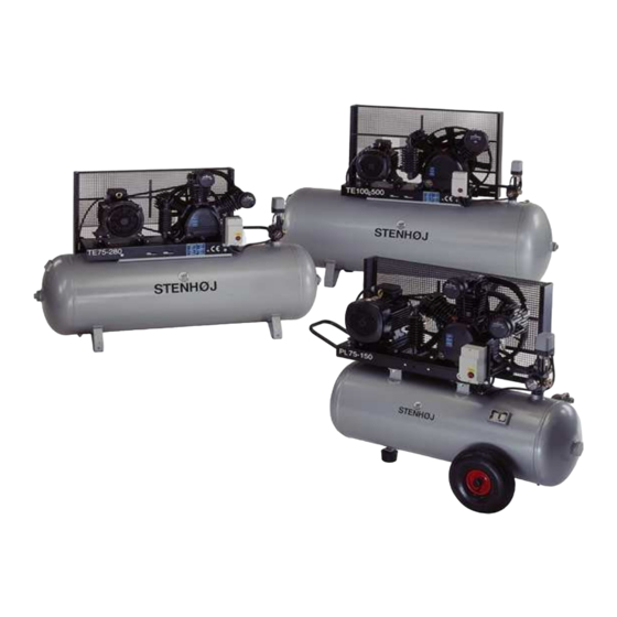
Piston compressors
B-LINE type PL/TE/PE
Rev.: 29-07-2005
Årgang 2005
User manual
STENHØJ A/S
DK-7150 Barrit
+45 7682 1330
Fax +45 76 82 1331
Internet www.stenhoj.dk
E-mail:infor@stenhoj.dk
T63514
Version
Summary of Contents for Stenhoj T63514
- Page 1
STENHØJ T63514 Piston compressors B-LINE type PL/TE/PE Rev.: 29-07-2005 Årgang 2005 VersionUser manual STENHØJ A/S DK-7150 Barrit +45 7682 1330 Fax +45 76 82 1331 Internet www.stenhoj.dk E-mail:infor@stenhoj.dk…
-
Page 2: Table Of Contents
Congratulations with your new imported STENHØJ piston compressor. Please read and follow these instructions carefully, prior to using your new piston compressor. Contents Page List of types 1.1 Name plate 1.2 Technical data Before using your compressor 2.1 Safety precautions Function 3.1 Function 3.2 Usage…
- Page 3
1.0 List of models 1.1 Name plate [ Date ] [ Type ] [ Serial no. ] [ Working pressure 1.2 Technical data Model no. Model Size of air Output R.P.M. No of Pressure Pressure D-O-L Motor receiver [L/min] cylinders stage [bar] [Kw]… -
Page 4: Before Using Your Compressor
2.0 Before using your compressor When you have unpacked your compressor, kindly check carefully that the product is without defects and that nothing is missing. Kindly contact your STENHØJ distributor if you should find defects . Stationary compressor units must be mounted on vibration dampers. Connection to mains supply always to be carried out by STENHØJ service engineer or authorized electrician.
-
Page 5: Limitations
3.3 Limitations Do not use compressed air directly as breathing matter. If you require air in such a quality, kindly contact your STENHØJ distributor. If you have any questions in this regard, please contact your STENHØJ distributor. IMPORTANT Never direct outlet air towards human beings or animals. 4.0 Operation instructions 4.1 Where to place the compressor unit The compressor unit can be placed any place dry and frost-proof.
-
Page 6: Pressurizing
4.4 Pressurizing If motor is overloaded, the motor starter will stop the compressor unit. For safety rea- sons a safety valve is fitted with the pressure switch, the function of which is to equalize pressure if this exceeds max. allowable pressure for the unit in question. Do no touch the safety valve.
-
Page 7: Maintenance
5.0 Maintenance 5.1 Maintenance The lifetime of the compressor unit depends on the maintenance carried out. There- fore check regularly oil level, belt tension and suction filter, and keep compressor block and motor clean. (Especially oleaginous dust on ribs reduces cooling). Oil: Change oil after app.
-
Page 8: Trouble Shooting
6.0 Trouble shooting • IMPORTANT 1) Switch off the current before remowing any parts from the compressor. 2) Empty the air receiver of air before dismantling any part of the compres- sor unit’s pressure system. SYMPTOM CAUSE REMEDY A. Compressor unit will not Fault in electrical installation: Let an electrician check the elec- start automatically.
- Page 9
6.0 Trouble shooting SYMTOM CAUSE REMEDY F. Compressor can not at- Inlet underdimensioned, e.g. inlet pipe Dimension inlet pipe correctly — tain the required working between inlet and compressor. larger fresh air intake. pressure. Pressure gauge defective. Replace it. Unit too small in proportion to air con- Connect further capacity. -
Page 10: Warranty
6.0 Trouble shooting SYMTOM CAUSE REMEDY K. Compressor’s oil con- Too much oil in compressor. Check oil level 2 or 3 minutes sumption rises. after stopping. Leaks around crank case. Change packing and inspect pack- ing surface. Repair or replace de- fective parts.
-
Page 11: Spare Parts
8.0 Spare parts STENHØJ offers the following spare parts kit for the various compressor types. Kindly note that only the spare parts kits as listed below are available.The kits are defined on the following pages. Ref. no. Designation Compressor type C49409 Packing kit, complete PL30…
- Page 12
8.1 Drawing for compressorblock type PL30 8.1 Spare parts kit for compressorblock type PL30 -12-… - Page 13
Article no. C49409 Packing kit cpl. consist. of : Ref. no. Discription Qty. Cylinder head packing Packing for valve Packing for valveseat Packing for cylinder Oil filling assembly packing 1 Oil sight gauge packing Bearing seat packing * The spareparts kit is cpl. for the compressorblock Article no. - Page 14
8.2 Drawing for compressorblock type PL50 -14-… - Page 15
8.2 Spare parts kit for compressorblock type PL50 Article no. C49402 Packing kit cpl. consist. of : Ref. no. Discription Qty. Cylinder head packing Valve packing Valve seat packing Cylinder packing Oil filling assembly packing 1 Oil sight gauge packing Rear bearing seat packing * The spareparts kit is cpl. - Page 16
8.3 Drawing for compressorblock type PL75 -16-… - Page 17
8.3 Spare parts kit for compressorblock type PL75 Article no. C49406 Packing kit cpl. consist. of : Ref. no. Discription Qty. Cylinder head packing Packing for valve seat Packing for valve Packing for cylinder Oil sight gauge packing O-ring Rear bearing seat packing Cylinder head packing Packing for valve * The spareparts kit is cpl. - Page 18
8.3 Spare parts kit for compressorblock type PL75 Article no. C49207 Pistonring kit cpl. LP consist. of : Ref. no. Discription Qty. Packing for cylinder Pistonring kit Cylinder head packing Packing for valve * The spareparts kit is only for one cylinder Article no. - Page 19
8.4 Drawing for compressorblock type PL100 -19-… - Page 20
8.4 Spare parts kit for compressorblock type PL100 Article no. C49403 Packing kit cpl. consist. of : Ref. no. Discription Qty. Cylinder head packing Packing for valve seat Packing for cylinder O-ring Oil sight gauge packing Rear bearing seat packing * The spareparts kit is cpl. - Page 21
8.5 Drawing for compressorblock type TE50 -21-… - Page 22
8.5 Spare parts kit for compressorblock type TE50 Article no. C49404 Packing kit cpl. consist. of : Ref. no. Discription Qty. Cylinder head packing Packing for valve Packing for valve seat Packing for valve seat Packing for cylinder Cylinder head packing Oil sight gauge packing O-ring Rear bearing seat packing… - Page 23
8.5 Spare parts kit for compressorblock type TE50 Article no. C49205 Pistonring kit cpl. LP consist. of : Ref. no. Discription Qty. Packing for valve seat Packing for cylinder Pistonring kit Cylinder head packing * The spareparts kit is only for one cylinder. Article no. - Page 24
8.6 Drawing for compressorblock type TE75 -24-… - Page 25
8.6 Spare parts kit for compressorblock type TE75 Article no. C49406 Packing kit cpl. consist of : Ref. no. Discription Qty. Cylinder head packing Packing for valve seat Packing for valve Packing for cylinder Oil sight gauge packing O-ring Rear bearing seat packing Cylinder head packing Packing for valve * The spareparts kit is cpl. - Page 26
8.6 Spare parts kit for compressorblock type TE75 Article no. C49207 Pistonring kit cpl. LP consist of : Ref. no. Discription Qty. Packing for cylinder Pistonring kit Cylinder head packing Packing for valve * The spareparts kit is only for one cylinder. Article no. - Page 27
8.7 Drawing for compressorblock type TE100 -27-… - Page 28
8.7 Spare parts for for compressorblock type TE100 Article no. C49408 Packing cpl. consist of : Ref. no. Discription Qty. Cylinder head packing Packing for valve seat Packing for cylinder O-ring Oil sight gauge packing Rear bearing seat packing O-ring Cylinder head packing Packing for valve seat * The spareparts kit is cpl. - Page 29
8.7 Spare parts kit for compressorblock type TE100 Article no. C49209 Pistonring kit cpl. LP consist of : Ref. no. Discription Qty. Cylinder head packing Packing for valve seat Packing for cylinder Pistonring kit * The spareparts kit is only for one cylinder. Article no. - Page 30
8.8 Drawing for compressorblock type PE 50B -30-… - Page 31
8.8 Spare parts kit for compressorblock type PE 50B Article no. C49405 Packing kit cpl. consist. of : Ref. no. Discription Qty. Cylinder head packing Packing for valve seat Packing for cylinder O-ring Oil sight gauge packing Rear bearing seat packing * The spareparts kit is cpl.
-
Contents
-
Table of Contents
-
Troubleshooting
-
Bookmarks
Quick Links
STENHØJ
Piston compressors
B-LINE type PL/TE/PE
Rev.: 29-07-2005
Årgang 2005
User manual
STENHØJ A/S
DK-7150 Barrit
+45 7682 1330
Fax +45 76 82 1331
Internet www.stenhoj.dk
E-mail:infor@stenhoj.dk
T63514
Version 
Summary of Contents for Stenhoj T63514
-
Page 1
STENHØJ T63514 Piston compressors B-LINE type PL/TE/PE Rev.: 29-07-2005 Årgang 2005 Version User manual STENHØJ A/S DK-7150 Barrit +45 7682 1330 Fax +45 76 82 1331 Internet www.stenhoj.dk E-mail:infor@stenhoj.dk…
 -
Page 2: Table Of Contents
Congratulations with your new imported STENHØJ piston compressor. Please read and follow these instructions carefully, prior to using your new piston compressor. Contents Page List of types 1.1 Name plate 1.2 Technical data Before using your compressor 2.1 Safety precautions Function 3.1 Function 3.2 Usage…
-
Page 3
1.0 List of models 1.1 Name plate [ Date ] [ Type ] [ Serial no. ] [ Working pressure 1.2 Technical data Model no. Model Size of air Output R.P.M. No of Pressure Pressure D-O-L Motor receiver [L/min] cylinders stage [bar] [Kw]… -
Page 4: Before Using Your Compressor
2.0 Before using your compressor When you have unpacked your compressor, kindly check carefully that the product is without defects and that nothing is missing. Kindly contact your STENHØJ distributor if you should find defects . Stationary compressor units must be mounted on vibration dampers. Connection to mains supply always to be carried out by STENHØJ service engineer or authorized electrician.
-
Page 5: Limitations
3.3 Limitations Do not use compressed air directly as breathing matter. If you require air in such a quality, kindly contact your STENHØJ distributor. If you have any questions in this regard, please contact your STENHØJ distributor. IMPORTANT Never direct outlet air towards human beings or animals. 4.0 Operation instructions 4.1 Where to place the compressor unit The compressor unit can be placed any place dry and frost-proof.
-
Page 6: Pressurizing
4.4 Pressurizing If motor is overloaded, the motor starter will stop the compressor unit. For safety rea- sons a safety valve is fitted with the pressure switch, the function of which is to equalize pressure if this exceeds max. allowable pressure for the unit in question. Do no touch the safety valve.
-
Page 7: Maintenance
5.0 Maintenance 5.1 Maintenance The lifetime of the compressor unit depends on the maintenance carried out. There- fore check regularly oil level, belt tension and suction filter, and keep compressor block and motor clean. (Especially oleaginous dust on ribs reduces cooling). Oil: Change oil after app.
-
Page 8: Trouble Shooting
6.0 Trouble shooting • IMPORTANT 1) Switch off the current before remowing any parts from the compressor. 2) Empty the air receiver of air before dismantling any part of the compres- sor unit’s pressure system. SYMPTOM CAUSE REMEDY A. Compressor unit will not Fault in electrical installation: Let an electrician check the elec- start automatically.
-
Page 9
6.0 Trouble shooting SYMTOM CAUSE REMEDY F. Compressor can not at- Inlet underdimensioned, e.g. inlet pipe Dimension inlet pipe correctly — tain the required working between inlet and compressor. larger fresh air intake. pressure. Pressure gauge defective. Replace it. Unit too small in proportion to air con- Connect further capacity. -
Page 10: Warranty
6.0 Trouble shooting SYMTOM CAUSE REMEDY K. Compressor’s oil con- Too much oil in compressor. Check oil level 2 or 3 minutes sumption rises. after stopping. Leaks around crank case. Change packing and inspect pack- ing surface. Repair or replace de- fective parts.
-
Page 11: Spare Parts
8.0 Spare parts STENHØJ offers the following spare parts kit for the various compressor types. Kindly note that only the spare parts kits as listed below are available.The kits are defined on the following pages. Ref. no. Designation Compressor type C49409 Packing kit, complete PL30…
-
Page 12
8.1 Drawing for compressorblock type PL30 8.1 Spare parts kit for compressorblock type PL30 -12-… -
Page 13
Article no. C49409 Packing kit cpl. consist. of : Ref. no. Discription Qty. Cylinder head packing Packing for valve Packing for valveseat Packing for cylinder Oil filling assembly packing 1 Oil sight gauge packing Bearing seat packing * The spareparts kit is cpl. for the compressorblock Article no. -
Page 14
8.2 Drawing for compressorblock type PL50 -14-… -
Page 15
8.2 Spare parts kit for compressorblock type PL50 Article no. C49402 Packing kit cpl. consist. of : Ref. no. Discription Qty. Cylinder head packing Valve packing Valve seat packing Cylinder packing Oil filling assembly packing 1 Oil sight gauge packing Rear bearing seat packing * The spareparts kit is cpl. -
Page 16
8.3 Drawing for compressorblock type PL75 -16-… -
Page 17
8.3 Spare parts kit for compressorblock type PL75 Article no. C49406 Packing kit cpl. consist. of : Ref. no. Discription Qty. Cylinder head packing Packing for valve seat Packing for valve Packing for cylinder Oil sight gauge packing O-ring Rear bearing seat packing Cylinder head packing Packing for valve * The spareparts kit is cpl. -
Page 18
8.3 Spare parts kit for compressorblock type PL75 Article no. C49207 Pistonring kit cpl. LP consist. of : Ref. no. Discription Qty. Packing for cylinder Pistonring kit Cylinder head packing Packing for valve * The spareparts kit is only for one cylinder Article no. -
Page 19
8.4 Drawing for compressorblock type PL100 -19-… -
Page 20
8.4 Spare parts kit for compressorblock type PL100 Article no. C49403 Packing kit cpl. consist. of : Ref. no. Discription Qty. Cylinder head packing Packing for valve seat Packing for cylinder O-ring Oil sight gauge packing Rear bearing seat packing * The spareparts kit is cpl. -
Page 21
8.5 Drawing for compressorblock type TE50 -21-… -
Page 22
8.5 Spare parts kit for compressorblock type TE50 Article no. C49404 Packing kit cpl. consist. of : Ref. no. Discription Qty. Cylinder head packing Packing for valve Packing for valve seat Packing for valve seat Packing for cylinder Cylinder head packing Oil sight gauge packing O-ring Rear bearing seat packing… -
Page 23
8.5 Spare parts kit for compressorblock type TE50 Article no. C49205 Pistonring kit cpl. LP consist. of : Ref. no. Discription Qty. Packing for valve seat Packing for cylinder Pistonring kit Cylinder head packing * The spareparts kit is only for one cylinder. Article no. -
Page 24
8.6 Drawing for compressorblock type TE75 -24-… -
Page 25
8.6 Spare parts kit for compressorblock type TE75 Article no. C49406 Packing kit cpl. consist of : Ref. no. Discription Qty. Cylinder head packing Packing for valve seat Packing for valve Packing for cylinder Oil sight gauge packing O-ring Rear bearing seat packing Cylinder head packing Packing for valve * The spareparts kit is cpl. -
Page 26
8.6 Spare parts kit for compressorblock type TE75 Article no. C49207 Pistonring kit cpl. LP consist of : Ref. no. Discription Qty. Packing for cylinder Pistonring kit Cylinder head packing Packing for valve * The spareparts kit is only for one cylinder. Article no. -
Page 27
8.7 Drawing for compressorblock type TE100 -27-… -
Page 28
8.7 Spare parts for for compressorblock type TE100 Article no. C49408 Packing cpl. consist of : Ref. no. Discription Qty. Cylinder head packing Packing for valve seat Packing for cylinder O-ring Oil sight gauge packing Rear bearing seat packing O-ring Cylinder head packing Packing for valve seat * The spareparts kit is cpl. -
Page 29
8.7 Spare parts kit for compressorblock type TE100 Article no. C49209 Pistonring kit cpl. LP consist of : Ref. no. Discription Qty. Cylinder head packing Packing for valve seat Packing for cylinder Pistonring kit * The spareparts kit is only for one cylinder. Article no. -
Page 30
8.8 Drawing for compressorblock type PE 50B -30-… -
Page 31
8.8 Spare parts kit for compressorblock type PE 50B Article no. C49405 Packing kit cpl. consist. of : Ref. no. Discription Qty. Cylinder head packing Packing for valve seat Packing for cylinder O-ring Oil sight gauge packing Rear bearing seat packing * The spareparts kit is cpl.

T62262 INSTALLATION AND MAINTENANCE MANUAL M 2.30 F STENHØJ AUTOLIFT A/S DK-7150 Barrit + 45 76 821330, telefax + 45 76 821331 E-mail: [email protected] / www.stenhoj.dk Pdf downloaded from http://www.thepdfportal.com/m2.30fmanual_243951.pdf Date: 210610 Serial No: Ref.: /gf Pages: 31 1 Table of contents EC Declaration of Conformity .................................................................................................. 2 Delivery / Transport / Stacking ................................................................................................ 3 Delivery and Installation requirements ................................................................................... 4 Most important designations according to new concrete standard B 4710-1 .......................... 6 Concrete strength classes ...................................................................................................... 6 Conventional applications ....................................................................................................... 7 Safety devices ......................................................................................................................... 7 Important installation instructions ........................................................................................... 8 Practical use of the lifts ........................................................................................................... 9 Testing of lifts ........................................................................................................................ 10 Disposal of the lifts ................................................................................................................ 10 Technical details ................................................................................................................... 11 Product description ............................................................................................................... 13 Foundation ............................................................................................................................ 14 Floor fixing for lifts up to 4 t .................................................................................................. 15 Foundation work for lifts up to 4 t ......................................................................................... 16 Installation and initial operation ............................................................................................ 17 Safety lock device (load nut failure) ..................................................................................... 18 Replacement of nut set ........................................................................................................ 20 Emergency lowering .............................................................................................................. 21 Maintenance and service ..................................................................................................... 22 Maintenance schedule .......................................................................................................... 22 Ribbed V-belt ........................................................................................................................ 23 Pick-up pads ......................................................................................................................... 23 Control unit ............................................................................................................................ 24 Connection of circuit board.................................................................................................... 25 Electric diagram .................................................................................................................... 26 Spare parts drawing ............................................................................................................. 27 Swing arm M 2.30 F standard-series .................................................................................... 30 Spare parts list ..................................................................................................................... 31 Pdf downloaded from http://www.thepdfportal.com/m2.30fmanual_243951.pdf T62262 T62262 2 STENHØJ AUTOLIFT A/S Barrit Langgade 188-190 DK-7150 Barrit Tel.: + 45 76 82 13 30 Fax: + 45 76 82 13 31 CVR-nr. 16 92 61 91 E-mail: [email protected] Homepage: www.stenhoj.dk EC Declaration of Conformity in accordande with the EC Machine Directive 2006/42/EC, Annex II A Automotive lift: M 2.30 F Model No.: 097001 Serial No.: 2-post surface-mounted lift Max. lifting capacity: 3000 kg Manufacturer: STENHØJ AUTOLIFT A/S Barrit Langgade 188-190 DK – 7150 Barrit Year: 2010 We hereby declare that the above mentioned machine, by its design and construction and equivalent with the version put on the market by us, complies with the essential fundamen-tal health and safety requirements. In case of any modification in the machine unapproved by us this certificate becomes void. Relevant EC-Directives: - EC-Machinery Directive 2006/42/EC - Low Voltage Directive 2006/95/EC - Electromagnetic Compatibility Directive 2004/108/EC Harmonized standards applied: - EN 1493:1998 + A1:1:2008 - EN 12100-1; EN 12100-2 - EN 60204-1 - EN 954-1:1996 Responsible for documentation Søren Madsen, Barrit Langgade 188-190, DK-7150 Barrit Barrit, 2010 Anders Jul Nielsen Engineering Manager EC Declaration of Conformity - Form EC-GB Revision: Pdf downloaded from http://www.thepdfportal.com/m2.30fmanual_243951.pdf T62262 3 Delivery / Transport / Stacking Dimensions: Lift type 1-post lift 2-post lift 4-post lift A 700 690 970 B 3100 3100 3100 C 700 570 450 + Platforms Scissor lift Scissor lift with free wheel lift 800 680 5000 1660 450 790 Dimensions in mm! Max. 4 pieces Working place area 2-post lift Required floor space Minimum 1 m in front, laterally and behind the vehicle / lift 7m 3,5 m Pdf downloaded from http://www.thepdfportal.com/m2.30fmanual_243951.pdf T62262 4 Delivery and Installation Requirements 1. Delivery by forward company invoiced with standard freight charge: A forklift must be made available at short notice. Weight of the lifts: approx. 650 – 2700 kg, depending on lift type. 2. Delivery by truck with off - loading equipment invoiced with increased freight charge: Equipment for deposition assistance must be provided at short notice. Weight of the lifts approx. 650 – 1000 kg, depending on lift type 3. Preparations for installation Prior to setting up following work must be arranged by the operator: ♦ Preparation of the fundament (see standard foundation). ♦ Laying of electrical connection to place of installation site. ♦ Transport of lift to place of installation site. 4. Minimum foundation requirements The foundation surface must be flat and horizontal for all lifts. The foundation must correspond to the general guidelines for foundations (DIN 1054). For lifts installed outside, the foundation must be frost-proof. In case of ceiling installation, the floor conditions must be certified by a structural engineer. Lifts are be anchored with special chemical bolts or through bolts, minimum strength 8.8 and washers (are not delivered with the lift). 5. Performances of our customer service section The customer service or the authorised partners take on the setting up of the lift with the following criteria: - Fixing to the floor. - Fitting of the lift. When installing the lift, additional personnel, and/ or auxiliary lifting means must be provided at short notice. - Electrical functional check and trial run without final mains connection (which must be carried out by a local specialist). - Permanent connection of cables between posts on 2-post lifts only if the cable portal is used - Short instruction. 6. Average time for installation (providing the conditions above are met): Approx. 4 hours working time The electrical connection cables are only assembled permanently with the use of a cable portal (accessory). Otherwise these cables must be fixed by the operator. Revision: Pdf downloaded from http://www.thepdfportal.com/m2.30fmanual_243951.pdf 5 T62262 If the lift is installed by the operator himself, the attached assembly and operating instructions must be observed. Subsequently the lift must be subjected to safety acceptance by the customer service. This includes the following performances: Electrical functional check and trial run. Examination of the individual structural components. Short instruction. 7. Annual check In addition to the check prior to the initial commissioning of the lift by our customer service department, the official regulations demand at least one safety inspection per year by experts. Our customer service will be pleased to submit you a quotation for a maintenance contract. 8. Installation cost rates and invoicing The performances of the customer service stated are invoiced in accordance with the respectively applicable terms and conditions of installation, hourly rates and lump-sum travelling amounts. Fixing material is not included in the scope of delivery of lifts. 9. Guarantee Based on the fact that lifts must satisfy specify safety requirements for protection of persons working of them, we draw your attention to the fact that we must tie the guarantee entitlement of the operator to the correct performed safety acceptance. Always uses original spare parts. The use of any other parts invalidates the design permit and all claims under warranty. Pdf downloaded from http://www.thepdfportal.com/m2.30fmanual_243951.pdf T62262 6 The most important designations according to the new concrete standard B 4710-1 Exposition classes (environmental classes) XO XC1 XC2 XC3 XC4 no corrosion risk, no frost; corrosion released by carbonation X0 non-reinforced concrete, concrete in buildings with < 30% air humidity XC1 concrete in buildings (flats, offices), kitchens, bathrooms, laundries; foundations in the groundwater XC2 interiors with high air humidity, laundries, cattle sheds, indoor swimming pools, not oppressive groundwater, water pressure height under 2 m XC3 water pressure height 2 to 10 m; seal concrete buildings (in former times: WU) XF1 Rain and frost demand for curved (> 5 %) and vertical surfaces, all under-faces with frost XF2 concrete with frost and rope means (salt) for curved (< 5%) and horizontal surfaces XF3 rain and frost demand for horizontal surfaces; hydraulic engineerings F4 concrete with frost and rope means (salt) for horizontal surfaces (in former times: FTB) Concrete strength classes The new strength classes are to be compared approximately as follows: C 8/10 C12/15 C16/20 B 8/B 80 B 15/B 160 B20 / B225 C20/25 B25 Revision: Pdf downloaded from http://www.thepdfportal.com/m2.30fmanual_243951.pdf 7 T62262 Conventional applications Your lift has been design-tested in its basic concept, this lift offers you maximum economic efficiency and safety. It is up to you to make use of these advantages. A prerequisite for this is correct operation, perfect maintenance and good care of the lift. Please read these operating instructions carefully. They provide you with all necessary data and show how simple it is to keep your lift ready for use at all times. Your lift is only designed to raise passenger vehicles or vehicles whose total weight does not exceed the lifts’s maximum permitted load capacity and whose specified lifting points are within the lift’s lifting area. All 4 lifting points have to be used. Your lift is designed to raise motor vehicles. The transportation of people is not permitted. When using the lift in painting plants or rooms in which a large amount of work is carried out with solvent-containing materials, pay attention to the risk of explosion. In its standard form the drive is not protected against explosion. Safety devices Your lift is equipped with several safety devices, to ensure workers safety, if the lift is used according to this manual. Please take care of these safety devices, when installing the lift and check them after any case of failure. Only trained service people are allowed to repair this lift. Only original parts are to be used for repair. If third parts equipment is used for repair, the CE certificate of conformity will become void. In accordance with the regulations regarding the operation of lifts, lift devices must be checked for their operational safety by an expert at the latest after one year. Records must be kept of inspections. In this respect please pay attention to ensuring that only company-trained experts, who have been instructed in the function of lifts and who are in possession of a certificate from the manufacturing company, check and accept your lift. Pdf downloaded from http://www.thepdfportal.com/m2.30fmanual_243951.pdf T62262 8 Attention! Important instructions for assembling the 2-Post-Lift! 1. The assembly should be carried out by qualified staff in accordance with the construction and operating instructions (otherwise the guarantee will be invalidated). 2. Check that all parts have been delivered before starting installation. 3. Final installation checks must be carried out. 4. Test instructions are to be complied with. 5. Instructions for the foundation of the lift must be strictly observed. 6. Ensure that the motor axis is hanging parallel to the spindel axis. For any adjustment please loosen the screws from base plate and retighten them. 7. Check the locking mechanism of the swing arm, then ensure that the bolt is vertical and parallel to the front of the post. 8. The lift is pre-programmed in the factory and must be adjusted to local conditions. Check that the foot protection facility is at the correct height. 9. Beware of the alignment (outward leaning) of the posts. 10. Check the gap between the steering frame and the cover band (correct and grease the back of the cover band when necessary). 11. The self-securing swing arm screws (retaining device) is only completely hardened after 24 hours (check for a gap of 1 to 2 mm between the screw head and the swing arm bearing). 12. Observe maintenance schedule (swing arms, spindles, lifting pads). 13. For lifting, use all 4 swing arms only at the lifting points recommended by the manufacturer. Revision: Pdf downloaded from http://www.thepdfportal.com/m2.30fmanual_243951.pdf T62262 9 Practical use of the post-lifts The operating knob is in "ON" position. Turn the control knob to move the lift in the direction indicated by the arrows. On release of the operating knob it returns automatically to the “off” position. Operating of the lift is only permitted by authorised persons! According to the regulations for prevention of accidents, persons under the age of 18 are not permitted to operate the lift without supervision. The lift is designed only as a vehicle lift, it should not be used for other purposes. See instruction on the lift column. If there are any faults with the lift, turn off electricity, make safe, secure against unauthorised use and contact the service department. See the operation label on the lift column! Before lifting or lowering a vehicle check that nobody is in danger, that nothing is leaning against the vehicle and no obstacles are underneath it. Attention: With some vehicles, higher lifting apparatus is necessary. If necessary, a set (4) spacing bushes is available. This ensures safe lifting of the vehicle. The total vehicle weight must not exceed the authorised capacity and load dispatching. Only original accessories may be used as load supporting devices (type tested parts), wooden blocks or other devices for load lifting are not permitted. It is advisable that the vehicle should be driven on so that the centre of gravity is between the lift columns (especially with the asymmetric swing arms). In order to guarantee a safe raising of the vehicle it may only be lifted at all 4 lifting points as stipulated by the manufacturer. Check the safety of the lifting once again after having raised the vehicle a little. Pay attention to the centre of gravity when working with heavy parts as it can cause the vehicle being raised to fall. Only use the lift as intended: for lifting vehicles. Other, apparently practical uses are not among is intended purposes. It is forbidden to use the lifts to raise heavy vehicle parts, eg, engines. The swing arms are fitted with blocking devices which work automatically. They will block the moving of the swing arms after a short lifting distance and release again when lowered (approx. 15 mm). If the arms have to be swung in a greater height, eg, in order to place a vehicle on a bench, then a hand lever can be installed, so that the arm locking device can be released manually. Pdf downloaded from http://www.thepdfportal.com/m2.30fmanual_243951.pdf T62262 10 Testing of lifts The testing of lifts is to be carried out in accordance with the local safety regulations ! The required tests are carried out by manufacturer’s construction department according to the regulations. Please ask your commercial partners for their reasonably priced maintenance contracts. Disposal of the post lift The lift can be disassembled and be disposed of only through an authorised specialist. The same regulations must be considered, as when installing the lift. For the case of scrapping, all materials must be disposed in accordance with the laws of the appropriate country, in which the lift is installed. The scrapping of the lift must be documented according to the country, in which this was installed. Attention! When loading/unloading, moving, installing, assembling or dismantling the lift all precautionary measures are specified by rules for the prevention of accidents (safety helmets, gloves, shoes) are to be obeyed. These rules are in accordance with the laws of the appropriate country. Revision: Pdf downloaded from http://www.thepdfportal.com/m2.30fmanual_243951.pdf T62262 11 Technical details Type: Remark: Width (mm): Height (mm) approx.: Max. vehicle width (mm): Range (mm): Lifting height (mm): Min. arm clearance (mm): Lifting time (sec): Nett weight (kg): Capacity (kg): M 2.30 F with asymmetric swing arms 3315 2550 2350 1.920 2005 85 45 500 3000 * Motor power (kW): Voltage (V): ED-power: Current (A): Fuse rating (A gl): Noise level (dB(A)): 2x3 400 S3 – 10% 16 20 78 Subject to change without prior notice ! * The load distribution should not exceed the ration 3:2 !!! Pdf downloaded from http://www.thepdfportal.com/m2.30fmanual_243951.pdf T62262 Dimensions of the 2-post lift M 2.30 F Subject to modification without prior notice ! Revision: Pdf downloaded from http://www.thepdfportal.com/m2.30fmanual_243951.pdf 12 13 T62262 Product description The lift basically consists of the main post and a slave post. In both posts the lifting spindles and the lifting carriages with load bearing device are to be found. The drive turns the lifting spindle. On the spindles there are nuts which are attached to the lifting carriage which, according to the turning direction of the drive, moves up or down and thus performs the raising and lowering operation. The lifting carriage is driven on maintenance free roller bearings within the column. In each post a motor driven belt turns the spindles. The even running of the lifting carriages is ensured via an electronic synchronizing system (potentiometers). Any uneven running of the lifting carriages (eg, because of an uneven load, lack of lubrication, etc) is regulated by the synchronization control within a distance of approximately 10 mm. The lifting carriage which is in front is briefly stopped until the slower carriage reaches the same height. This levelling may be observed several times in the course of the lift. By shifting the operating knob on the control box the lifting motion corresponding to the movement symbols is switched on. When the lift reaches top position it stops automatically (potentiometer); the same happens in bottom position. The potentiometer also controls the safety stop: For safety reasons, the downward movement is programmed to automatically stop at a height of 200 mm (between the floor and the underside of the lifting device). By releasing and the re-engaging the operating knob the carriages lower together with the sound of a warning tone. The operating knob goes automatically back to stop position when released and the movement of the lift is stopped in the corresponding position of the carriage. In addition, the lift is equipped with a variety of both passive and active safety devices. An example of this would be the safety device for broken load bearing nuts which transfers the load to a safety nut in the event of a worn thread. At the same time, a mechanical blocking system is engaged which prevents continued movement to the lowered position in the event of worn threads. In this way, unintentional travel on the safety nuts is avoided. The swing arm lock locks the load arms moving after running upward a short distance from the lowered position. This is to prevent the lifting device slipping from the lifting points on the vehicle being raised. The safe positioning is to checked ! The thermo sensors in the motors stop the lift in the event of overheating and only allow the lift to re-start after a cooling down period. The M 2.30 2-post lift is used with asymmetrical arms. A maximum capacity of only 3.000 kg and a maximum weight distribution of only 3:2 is allowed. When using the asymmetrical version of the arms, the swing arms have difference length. The vehicle has to be placed in drive-on direction with the short-double telescopic pick up arms in front and the long arms, only single telescopic, backwards. The vehicle to be lifted is positioned so that the front door hinges are close to the lift columns in order to facilitate a wide opening of the doors. It is desirable that the vehicle’s engine is towards the short swing arm (the centre of gravity of the vehicle as close as possible to the centre of the lift)!. All 4 lifting points are positioned at the jacking points stipulated by the vehicle manufacturer! Pdf downloaded from http://www.thepdfportal.com/m2.30fmanual_243951.pdf T62262 14 Foundation As the M 2.30 F is of a “baseless” design, the floor fixing is critical .The entire load (dead weight of lift and moving weight of vehicle) are transferred to the floor through the chemical bolts. Before installing the lift, it is necessary to ensure that the floor is adequate (see supplement anchoring for lifts). When installing the lift on a ceiling, the floor’s suitability must be verified by a structural engineer, or other competent person. Only after checking of the available underground, a decision can be made about the corresponding anchoring. The penetration depths of the anchors (anchors are not supplied) have to be followed (see instructions of the anchor manufacturers). Otherwise the safety of the lift may be compromised. The correct length (L) of the active part of the anchor bolt is obtained by adding the measurements „h“ + thickness of the floorcover and height of the files and the height of the installation base. Drill size and the thightening torque are in accordance to the bolt manufacturers instructions. To achieve a perfect installation, the undamaged concrete floor should be flat and level (min. C20/25, frost proof) with the corresponding load capacity. According to the type of anchor used for the 21+1 mm hole in the base plate, the washers must be of sufficient size! Revision: Pdf downloaded from http://www.thepdfportal.com/m2.30fmanual_243951.pdf T62262 15 Floor fixing for lifts up to 4 t B H s t g L X = floor thickness (21 cm) = anchoring depth of anchors = thickness of ground covering - concrete C20/25 = thickness of component = threaded length = length of anchors = according to indications of manufacturer Length of anchors: L = h + s + t + g Depending on the type of anchoring, use approximatelysized washers for 21+1 mm drill holes in the base plate. Subject to change without prior notice ! Pdf downloaded from http://www.thepdfportal.com/m2.30fmanual_243951.pdf T62262 16 Foundation work for lifts up to 4 t Underground: Concrete without damage Perm. SigmaB >= 200 kN/m² C20/25 BST 500 M Concrete floor> 2,0 cm Perm. SigmaB >= 150 kN/m² M 2.30 F X = 374 cm Y = 257 cm Floor plate C 20/25 concrete without damage Thickness: d ≥ 21 cm necessary asx = 2,57 cm²/m - lower reinforcement necessary aSx,y = 3,77 cm²/m - upper reinforcement Fixing of post: BST 500 M BST 500 M Hilti HVA/HAS-M12x110 mm (or equivalent quality) Important: Always follow the installation instructions and keep to the min. anchoring depths specified by the anchor manufacturers ! Tests on existing concrete floor are necessary for anchoring ! Revision: Pdf downloaded from http://www.thepdfportal.com/m2.30fmanual_243951.pdf 17 T62262 Installation and initial operation In order to install a lift correctly the concrete must be flat and horizontal and have the required load strength (minnimum C20/25). First of all the posts are placed on their staying positions. The distance dimensions of the base plates of the posts are shown in the relevant sketch of dimensions. In accordance with EN1493 there must be a safety margin of 500 mm minimum between the posts and any other obstacle (wall, etc) and, similarly, between any load to be raised and another obstacle. After repeated checking of the installation situation, the base plate is anchored through the existing drilled holes (the base plates must lie on with their entire surface!). According to the chapter “Foundation”, 12 special chemical bolts M12 are required. Other equivalent chemical bolts can also be used that have been appproved for the concrete by the building supervisory authorities, resp. for this region. Chemical anchors are not supplied. The posts of the lift must be vertical. They must in no case lean inwards. A slight outward lean (up to 10 mm) is desirable. If necessary, extra shims can be placed between the column base plates and the floor for levelling purposes. In the slave post there are the cables which are connected to the main post. These cables are connected to the main post. A cable portal can also be purchases additionally for this connection. When installing the cables it is important to ensure that the wires are not mixed up! Before starting the electrical work, please read and observes the instructions regarding initial installation (following pages) carefully! For further questions, our service department is available. The electrical installation for the lift must be carried out by an electrical engineer and according to the enclosed circuit diagram. The lift should operate in accordance with the travel direction symbols when the operating knob is activated. If necessary, change the direction of turn by interchanging the 2 phases. Grease the arm locking bolts thoroughly. When the arms have been fitted it has be checked that the locking piece has engaged in the toothing. The lift has to be lubricated at the post according to the lubrication schedule (following pages). Securing of the lifting device (eg, swing armes) against being disconnected: Fit the arm locking device in such a way that there remains a gap of 1 to 2 mm between the screw head and the upper edge of the swing arm. Attention: The self-securing screws are completely hardened only after 24 hours. There must be sufficient space between the bracket for the cover band and the post so that the cover does not get damaged. The brackets may need to be adjusted.The spindles must be greased. Should there be a noise from the cover bands when the lift is running then multi-purpose grease can be applied to the back of the cover band. By doing a test run, check the limits and the safety stop. If the lift does not come down to the height required the following has to be done: - Lower lift to bottom position - Loosen the bolt for potentiometer bracket - On both post 1 and post 2: disengage potentiometer (allen bolt), turn the spindle manually down to the height required. - When the distance required to floor has been reached re-fit potentiometer. - Test the lift. After examination of the function of the lift by experts, the start-up can take place. Pdf downloaded from http://www.thepdfportal.com/m2.30fmanual_243951.pdf T62262 18 Safety lock device (load nut failure) Your lift is equipped with a safety lock that stops the operation if a nut has failed. For explanation of the function of the safety lock device, please check the following sketch. Fig. 2 and 3 show the position of load nut and respectively safety nut with the angled safety catch between nuts on the driving angles. The load carrying device is fitted into the lifting carriage and cannot be accessed from outside. When using the lift in normal operation, there is a clearance between safety nut and carriage which allows the safety nut to run without load. If the thread of the load nut is worn out, the load nut will fail. In this case the carriage falls on the safety nut and activates the safety lock which presses against the back wall of the post (see fig. 3). If the lift is running on the safety nut once, it can be lowered. If the carriage is moved upwards again, the safety lock catches on the back wall of the lift and stops the raising of the lift. The locking mechanism must under no circumstances be disconnected. If the lift stops about 10 mm above the ground level, the safety catch is engaged. Load nut failures can only be repaired by qualified lift engineers ! To prevent load nut failure, the below check-up should be carried out periodically: Faulty or improper repairs can be a danger to people remaining below the lift ! Load nut testing (once a year) With inspection nut „trapezoidal thread Tr45x6”, available as special accessory (Ident-Nr.: 35416.7). 1. Remove the flexible cover so that the load nut can be seen in the carriage. 2. Using a bar, lift the carriage as and hold. 3. Fix the testing nut (accessory) on the spindle, turn anti-clockwise until it touches the load nut 4. Lower the carriage 5. Measure the gap between the load nut and the testing nut with a gauge or vernier. If the wear is over 1mm, the load nut must be replaced! Revision: Pdf downloaded from http://www.thepdfportal.com/m2.30fmanual_243951.pdf T62262 19 Load nut failure Load nut Carriage Block Safety lock Safety nut To be greased every 3 monts (see Maintenance and Service) Fig. 2 Load nut okay Fig. 3 Load nut destroyed Pdf downloaded from http://www.thepdfportal.com/m2.30fmanual_243951.pdf T62262 20 Replacement of nut set When replacing the nut set please take care that the distance between bottom of carriage and bottom of safety nut must be at least 30 mm. Revision: Pdf downloaded from http://www.thepdfportal.com/m2.30fmanual_243951.pdf 21 T62262 Emergency lowering Important: During emergency lowering procedure, the automatic end limits are switched off. If lowering the lift onto mechanical limit stops the lift might be damaged Notes: The procedure described below for lowering in an emergency case must only be executed by authorised and trained personnel. A second person should take care about this procedure from outside the operating area to ensure the safety of the operator and vehicle. The emergency lowering procedure must be stopped immediately, if any danger should arise and re-started when cause of danger has been removed. It is only possible to lower the lift once, making sure that the arms do not touch the floor. Operation of emergency lowering procedure: An emergency lowering by using the motors can be necessary if the electronic controls fail. If other elements fail, then the lift should be lowered manually (by turning the bolt on the large pulley). The control knob must be turned on position “0” or off. If both carriages are not at the same height, it is possible to lock only one contactor from „0“ position to „1“ position and the arms can be brought on the same level. This levelling should be done in small steps and with increased attention. Operation the contactors The emgergency lowering can be carried out through mechanical operation of the contactors, by turning the operating knob onto 1 (down) and operate the contactor manually. Warning: No automatic end limit switchingoff When the maximum necessary lower position of the arms has been reached, the emergency lowering can be stopped immediately. The lift can be used again, only after removing of all defects by authorised personnel. K1 – Contactor main post Motor 1 down K2 – Contactor slave post Motor 1 down Different contactors can be used. ABB contactor Colour: black Condor contactor Colour: grey Pdf downloaded from http://www.thepdfportal.com/m2.30fmanual_243951.pdf T62262 22 Maintenance and service Before doing any servicing or maintenance the electricity supply must be cut off and the lift should be protected from any unauthorised use! For a long lift cycle and constant readiness of the lift the maintenance is an absolutely paramount issue. In certain conditions (e.g. increased use, low temperature, etc.) the spindle has to be greased separately (Molybdenum disulphide grease Mo2S). At least once a month you should check that the grease provision is sufficient. After installation and commissioning there may be some stretching of the power transmission elements, depending on the type of lift. For example, stretching of the drive belt, cables, consequential adjustments, adjustments to the safety systems, etc. These changes do not constitue wear and tear of the parts. They are routine aspects of working and must form part of the customer’s maintenance and care. With missing or poor care break downs can occur which are not covered by the guarantee. In this case, any costs arising may have to be paid by the customer. The swing arm joints must be greased when necessary and at least every 3 months (oil underneath the safety screws). Where lifts are exposed to the weather, the lubrication programme should be doubled (see the lubrication instructions on the main post). The lifting arms must always be kept in working condition. The buffer points must be kept clean and free of grease. The spindles of the turntables must be greased. They must not be able to unscrew themselves completely. Maintenance Schedule See chapter mechanical synchronization Abstract from „operation label“ Grease lifting spindle once a month with Molybdenum disulphide grease Keep pick up pad clean and free of grease Lubricate rollers and running surface with multipurpose grease twice a year! Keep lifting arms clean and free of grease See chapter Safety lock device! (load nut failure) Grease functional areas of lifting arm retainer periodically If the lift is used more heavily maintenance periods are to be shortened. Icon Meaning Icon Meaning Please read the manual and the inspection logbook. Keep clean and free of grease ! 1 Visual check Maintenance period every 6 months Lubricate with oil Maintenance period once a month Grease with multipurpose grease Maintenance period every 3 months Revision: Pdf downloaded from http://www.thepdfportal.com/m2.30fmanual_243951.pdf 23 T62262 Ribbed V-belt When the motor cover is removed and the lift is without load then the big belt pulley should be rotatable by hand (rough-running). The correct tension of the belt is 220-240 Hz. During operation: 195-220 Hz. Flex pick-up pad with attachable sleeve Subject to change without prior notice. Pdf downloaded from http://www.thepdfportal.com/m2.30fmanual_243951.pdf T62262 Control unit Revision: Pdf downloaded from http://www.thepdfportal.com/m2.30fmanual_243951.pdf 24 25 Main circuit board – Connection and initial operation 1. Connect main supply – clockwise direction of rotation. X3 - L1 ; X4 - L2 ; X2 - L3 ; X6 - N ; X7 - PE 2. Connect motor slave post on K2 slave post. Cable 1 – U ; Cable 2 – V ; Cable - W 3. Connect thermo motor slave post and PE. Cable 4 – THERMO ; Cable 5 – THERMO ; PE – PE Attention: take care about correct connection of PE !!!! 4. Connect potentiometer slave post. GREEN – X11- 6 ; WHITE – X11 - 7 ; BROWN – X11 - 8 5. 400V AC POWER ON – Drive mode. Lift is moving upwards. Attention: please observe sequence !! 6. Turn knob “UP” – main post moves downwards. Interchange main supply L1 and L2. 7. Turn knob “UP” – slave side moves downwards. Interchange cable 1 - U and cable 2 - W on contactor K2 – slave side. Pdf downloaded from http://www.thepdfportal.com/m2.30fmanual_243951.pdf T62262 T62262 Electric diagram Revision: Pdf downloaded from http://www.thepdfportal.com/m2.30fmanual_243951.pdf 26 27 Spare parts drawing Pdf downloaded from http://www.thepdfportal.com/m2.30fmanual_243951.pdf T62262 T62262 28 9 8 12 13 Y 10 W 16 15 11 6 17 V 5 X 14 12 7 6 Revision: Pdf downloaded from http://www.thepdfportal.com/m2.30fmanual_243951.pdf T62262 29 21 18 20 24 23 22 19 21 20 11 Pdf downloaded from http://www.thepdfportal.com/m2.30fmanual_243951.pdf T62262 30 Swing arm 27 25 26 27 Revision: Pdf downloaded from http://www.thepdfportal.com/m2.30fmanual_243951.pdf T62262 31 Spare parts list See page: 24 24 24 27 Item No.: 1 Reference: 27 27 28 28 28 28 28 28 28 28 28 28 28 28 29 29 29 29 29 29 29 30 30 30 2 4 5 7 8 9 10 11 12 13 14 15 16 17 18 19 20 21 22 23 24 25 26 27 CN491092 CN491118 CN488734 CN484857 CN484873 CN483727 CN489088 CN479600 CN259457 CN479972 CN481879 CN480087 CN485342 CN484816 CN484808 CN485359 CN484527 CN410084 CN483818 CN199703 CN358333 CN485243 CN485367 CN456434 CN484832 CN482943 CN483065 CN483214 777112 - - CN358671 CN362780 CN362798 CN488684 777231 Description: Operating knob Control box empty Control board cpl Motor cpl., main post Motor cpl., slave post Control unit Operation instructions sticker Ribbed V-belt pulley (big) Bolt for top plate (1 set for 1 column) Ribbed V-belt pulley (small) Ribbed V-belt Top plate Spindle bearing (bottom and top) Potentiometer bracket cpl. Top cover Bolt for V-belt pulley Post cover band cpl. (for 1 post) Carriage guiding rollers (4 pieces) Set of guiding blocks (1 set = 4 pieces) Cover (plastic) Bolt for arm locking device (4 pieces) Nut set cpl. (1 set for 1 post) Nut set accessories (1 set for 1 post) Arm locking device cpl. Lifting carriage cpl. Lifting spindle Swing arm asymmetric long (without pick-up pads) Swing arm asymmetric short (without pick-up pads) Pick-up pads complete vertical adjustable (1 set for 1 arm) Motor cable, 10 m - slave post Potentiometer 3-core cable - main post Potentiometer 3-core cable, 10 m long - slave post Door stop - rubber Chemical anchors Subject to change without prior notice ! Pdf downloaded from http://www.thepdfportal.com/m2.30fmanual_243951.pdf
- Manuals
- Brands
- Stenhoj Manuals
- Automobile Accessories
- Maestro 2.20
- Operation and maintenance instructions
-
Contents
-
Table of Contents
-
Troubleshooting
-
Bookmarks
Quick Links
DRIFTS- & VEDLIGEHOLDELSESVEJLEDNING
Operation AND MAINTENANCE INSTRUCTIONS
STENHØJ AUTOLIFT A/S
DK-7150 Barrit
+ 45 76 821330, telefax + 45 76 821331
E-mail: autolift@stenhoj.dk / www.stenhoj.dk
MAESTRO
BETRIEBS- UND WARTUNGSANLEITUNG
DRIFTS- OCH UNDERHÅLLSMANUAL
Date: 210207
Ref.: PML/LJE/gf
T61827
Serial No:
Pages: 34
Summary of Contents for Stenhoj Maestro 2.20
-
Page 1
MAESTRO DRIFTS- & VEDLIGEHOLDELSESVEJLEDNING OPERATION AND MAINTENANCE INSTRUCTIONS BETRIEBS- UND WARTUNGSANLEITUNG DRIFTS- OCH UNDERHÅLLSMANUAL STENHØJ AUTOLIFT A/S Date: 210207 Serial No: DK-7150 Barrit + 45 76 821330, telefax + 45 76 821331 E-mail: autolift@stenhoj.dk / www.stenhoj.dk Ref.: PML/LJE/gf Pages: 34… -
Page 2
MAESTRO T61827 Drifts- og vedligeholdelsesvejledning 2 — 9 Operation and maintenance instructions 10 — 17 Wartungs- und Bedienungsanleitung 18 — 26 Drifts- och underhållsmanual 27 — 34 Revision:… -
Page 3
Dette løfteaggregat er specielt konstrueret for løft af automobiler, hvorfor det stærkt frarådes at løfte alt andet udstyr med denne autoløfter. BESKRIVELSE Denne MAESTRO er en 2-søjlet elektromekanisk løfter med 2 motorer, automatisk ligestyring og en løftekapacitet op til: Model: Løftekapacitet: Maestro 2.20 2000 kg Maestro 2.25 2500 kg Maestro 2.30 3000 kg Maestro 2.32 3200 kg Maestro 2.37… -
Page 4
MAESTRO T61827 Hævning: Indstil svingarmene således, at konsollerne, der er beklædt med skridsikkert materiale, er anbragt under bilens bærende dele. Placer konsollerne omhyggeligt, så bilen ikke kan skride. Bemærk at konsollerne er dimensioneret efter en placering i forhold til bilens løftepunkter som vist på nedenstående skitse Center for løftepunkt Center for løftepunkt / Center of lifting point Center of lifting point… -
Page 5
T61827 MAESTRO Sikringer: se el-diagram. Revision:… -
Page 6
Kileremme: Disse bør efterjusteres én gang hvert år til den korrekte remspænding. Ved et kraftigt tryk midt på remmen må denne maksimalt kunne trykkes 5 mm sammen. Ekspansionsbolte: Disse efterspændes én gang hvert år med et moment på: Model: Efterspændingsmoment: Maestro 2.20 60Nm Maestro 2.25 60Nm 60Nm Maestro 2.30… -
Page 7
T61827 MAESTRO Rengøring: Rengøring af 2-søjlet overgulvsløftere, for forebyggelse af korrosions skader. Korrosive væsker som bremsevæske, olie, brændstof eller anden opløsningsvæske, skal aftørres med det samme, da der ellers vil ske skade på overfladebehandlingen. Særlig opmærksomhed skal rettes på den korrosive effekt af salt i efterår og vinter perioden. Rengøringsmidlerne må… -
Page 8
MAESTRO T61827 FEJLFINDINGSSKEMA SYMPTOM ÅRSAG AFHJÆLPNING Løfteren kan hverken Strømsvigt Efterse sikringer. Tilkald el-installatør hæves eller sænkes Overbelastning Fjern belastning og start igen Defekt elektronisk Tilkald montør sensor Fejl i det elektriske Tilkald autoriseret el-installatør system Løfteren kan ikke Obstruktion under arme Tryk på… -
Page 9
T61827 MAESTRO Fejlfinding: Aktiver kort ’OP’. Afkod den sekvens af bip der gives, eller observer blinkmønstret på LED3. Sekvensen består af i alt 8 bip/blink, OK-tilstand indikeres med kort signal, fejl indikeres med et langt. Fejl 1 til Fejl 4 – Fælles: Kontroller at forsyningsspændingen ligger indenfor det normerede spændingsområde, både under drift og i stilstand. -
Page 10
MAESTRO T61827 Ubalance under opkørsel – Sluk for hovedafbryder (se nedenfor) og kør manuelt de to stole i K1/Safety ikke trukket fuldstændig balance – kør løfteren i bundstiling for nulstilling af pulsværdier — følg vejl. i afsnittet ”forholdsregler omkring manuel Løfteren er kørt udenfor betjening af løfteren”… -
Page 11
T61827 MAESTRO OVERVÅGNING AF FØLERE / MOTORVÆRN: Det kontrolleres under kørsel, at afstanden mellem pulser ikke overskrider en forudbestemt tid. Hvis en af de tre magneter i kileremsskiven mangler, en føler er defekt, eller der af anden grund ikke aftastes korrekt , vil dette medføre en overskridelse af tiden, og løfteren går i stå. -
Page 12
DESCRIPTION This MAESTRO is a 2-post surface-mounted electro-mechanical lift with 2 motors, automatic synchronization and a lifting capacity up to : Model: Lifting capacity: Maestro 2.20 2000 kg Maestro 2.25 2500 kg Maestro 2.30 3000 kg Maestro 2.32… -
Page 13
T61827 MAESTRO Lifting: Position the adjustable arms in order that the skid-proof pick-up pads are placed under the supporting parts of the vehicle. Place the pick-up pads carefully in order to prevent the car from slipping off. Note that the pick-up pads are dimensioned in accordance with a positionning according to the lifting points of the vehicle as shown on the sketch below. -
Page 14
MAESTRO T61827 Fuses: See wiring diagram. Revision:… -
Page 15
V-belts: These must be re-adjusted once a year to correct tension: when pressing hard on the middle of the belt these must only be pressed 5 mm down. Expansion bolts: These must be re-tightened once a year with a torque of : Model: Torque: Maestro 2.20 60Nm Maestro 2.25 60Nm 60Nm Maestro 2.30… -
Page 16
MAESTRO T61827 Cleaning: Cleaning of 2-post surface mounted lifts to prevent corrosion damages. Corrosive fluids as brake fluid, oil, fuel or other solvents must be wiped off immediately, otherwise damage will occur to the coating. Special attention must be paid to the corrosive effect of salt in fall and winter periods. The cleansing agents must not have any abrasive effect, nor contain solvents. -
Page 17
T61827 MAESTRO TROUBLE SHOOTING CHART SYMPTOM CAUSE REMEDY Lift will neither Electricity cut Check fuses. Call authorized electrician raise nor lower Overload Remove load and re-start Defective electronic sensor Call authorized fitter Fault in the electrical system Call authorized electrician Lift cannot lower Obstruction under arms or Push UP-button and remove obstruction… -
Page 18: Trouble Shooting
MAESTRO T61827 Trouble shooting: Activate UP briefly. Decode the sequence of beeps given or observe the pattern of flashes on LED 3. The sequence consists of a total of 8 beeps/flashes. A short signal indicates OK-state, a long signal indicates error. Error 1 to 4 –…
-
Page 19
T61827 MAESTRO Obstruction / unbalance during lowering Is cancelled when UP-button is activated, so that UP still has the priority and the obstruction can be left. Check that there is no obstruction under the lift hindering it from lowering. If necessary activate UP to remove wedged objects. -
Page 20
MAESTRO T61827 For software versions ending on 64 and higher: Switch off lift. Get both carriages to bottom position and in balance. Is this already done, wait 30 sec. Switch on lift. Both bottom sensors must now be alight. The lift should now work and the trouble shooting can be continued. When replacing a circuit board the document T81701 ”Return note for circuit boards”… -
Page 21
Geräte mittels dieser Hebebühne zu heben. BESCHREIBUNG Diese MAESTRO ist eine 2-Säulen flurmontierte elektromechanische Hebebühne mit 2 Motoren, automatischem Gleichlauf und mit einer Tragfähigkeit von :. Modell: Tragfähigkeit: Maestro 2.20 2000 kg Maestro 2.25 2500 kg Maestro 2.30 3000 kg Maestro 2.32… -
Page 22
MAESTRO T61827 BEDIENUNG Die Hebebühne darf nur von bezüglich Betrieb und Wartung unterwiesenem Personal bedient werden. Positionierung des Fahrzeuges: Das Fahrzeug zwischen die beiden Säulen fahren und die vier Teleskoparme unter das Fahrzeug schwingen. Hubvorgang: Die Teleskoparme einstellen, so daß die Aufnahmen, die mit rutschhemmendem Material belegt sind, unter den tragenden Fahrzeugteilen stehen. -
Page 23
Druck auf die Mitte der Keilriehmen darf es nur møglich sein, sie 5 mm herunterpressen zu können. Schwerlastanker: Diese müssen einmal pro Jahr mit untenstehendem Moment nachgespannt werden. Modell: Nachspannungsmoment: Maestro 2.20 60Nm Maestro 2.25 60Nm 60Nm Maestro 2.30 60Nm Maestro 2.32… -
Page 24
MAESTRO T61827 Nachspannung der Schrauben am Säulenfuß: Diese müssen jede 12 Monate mit untenstehendem Moment nachgespannt werden: Modell: Nachspannungsmoment: Maestro 2.20 100Nm Maestro 2.25 100Nm 100Nm Maestro 2.30 100Nm Maestro 2.32 100Nm Maestro 2.37 Wenn eine oder mehrere der Schrauben während der Nachspannung brechen, müßen alle Schrauben am Säulenfuß… -
Page 25
T61827 MAESTRO Säule Stenhøj A/S akzeptiert keine Reklamation wegen Lackabschälungen oder Rostschäden, die durch fehlende oder ungenügende Reinigung oder Wartung verursacht sind. Schadenausbesserung Die Ausbesserung von Schäden an der Lackierung muß umgehend durchgeführt werden, um die Verbreitung des Schadensumfangs zu minimieren. Die Schäden werden typisch von folgenden Typen sein: Schäden, die nicht in der Metaloberfläche eindringt und in nur in der Lackierung liegt Schäden in der Metaloberfläche… -
Page 26
MAESTRO T61827 FEHLERSUCHE SYMPTOM URSACHE ABHILFE Die Bühne kann weder Stromausfall Sicherungen überprüfen. Elektrofachmann zu heben, noch senken Rate ziehen. Überlastung Hebebühne entlasten und wieder betätigen Defekter elektronischer Sensor Monteurhilfe erforderlich Fehler im elektrischen System Elektrofachmann zu Rate ziehen Die Bühne kann nicht Hindernis unter den Armen AUF-Taster betätigen und Hindernis entfernen gesenkt werden… -
Page 27
T61827 MAESTRO Fehlersuche: ”AUF” ganz kurz betätigen. Die abgebene Piepton-Sequenz dekodieren, oder das Blinkmuster auf LED3 beobachten. Die Sequenz besteht aus insgesamt 8 Pieptönen/Aufblitzen, OK-Sdand wird mit einem kurzen Signal angegeben, Fehler wird mit einem langen Signal angegeben. Fehler 1 bis 4 – Gemeinsam: Überprüfen, daß… -
Page 28
MAESTRO T61827 Unbalanz während dem Hauptschalter ausschalten (siehe unten) und die beiden Hubstühle manuell in vollständiger Balanz bringen – die Bühne zur untersten Heben – K1/Safery nicht Stelle senken, um die Pulswerte nullzustellen — die Vorschriften im gezogen Abschnitt ”Vorschriften für die manuelle Betätigung der Bühne” Die Bühne ist aus der folgen. -
Page 29
T61827 MAESTRO Für Software-Versionen, die auf 64 oder darüber enden: Die Bühne ausschalten. Beiden Hubstühle zur Bodenstellung und in Gleichstand bringen. Wenn dies schon erfüllt ist, dann 30 Sekunden warten. Die Bühne einschalten. Beide unteren Sensoren sollen leuchten. Die Bühne soll jetzt funktionieren, und die Fehlersuche kann evt. fortsetzen. Bei Austausch von Steckkarten soll das Dokument ”Return note for circuit boards”… -
Page 30
Denna lyftanordning är speciellt konstruerad för lyft av bilar, varför lyft av annan utrustning oavsett typ ej får förekomma. BESKRIVNING Denne MAESTRO är en 2-pelars golvmonterad elektromekanisk lyft med två elmotorer med en lyftkapacitet på : Model: Lyftkapacitet: Maestro 2.20 2000 kg Maestro 2.25 2500 kg Maestro 2.30 3000 kg Maestro 2.32 3200 kg Maestro 2.37… -
Page 31
T61827 MAESTRO MANÖVRERING Lyften bör endast användas av personal som är utbildade på lyftens funktioner och underhåll. Placering av fordon: Kör in fordonet och vrid lyftarmarna in under det. Lyftning: Ställ in armarna så att konsolerna, som är beklädda med glidsäkert material, är anbringade under fordonets lyftpunkter (se fordonets instruktionsbok). -
Page 32
Kilremmar: Dessa skall justeras en gång per år. Korrekt remspänning är när man med ett kraftigt tryck mitt på remmen får den att tryckas in max 5 mm. Expanderbultar: Dessa dras en gång varje år med ett moment på: Model: Efterdragningsmoment: Maestro 2.20 60Nm Maestro 2.25 60Nm Maestro 2.30 60Nm Maestro 2.32… -
Page 33
T61827 MAESTRO Revision:… -
Page 34
MAESTRO T61827 Om en eller flera skruvar gaar av vid efterdragning skall alla skruvarna vid pelarfoten bytas ut. OBS! Om lyften används för tvätt eller är placerad i en fuktig miljö skall skruvarna efterdras var 6:e månad. Smörjning: Lyften kräver endast tillsyn varje halvår, alla rörliga delar skall smörjas som följer: PLATS ÅTGÄRD SMÖRJMEDEL… -
Page 35
T61827 MAESTRO Reparationsmöjligheter: Kontakta BIMA för instruktion. Artikelnummer på reparationslack framgår av reservedelskatalogen och innehåller rengöring, primer og lack, samt hur man gör. Kom ihåg RAL-numret på lacken. GARANTI: Vid returnering av bifogade garantibevis skall det vara ifyllt och underskrivet omedelbart efter installation samt att de i denna manual angivna föreskrifterna avseende manövrering och underhåll uppfyllts, ges en ettårig fabriksgaranti för produktions- och materialfel. -
Page 36
MAESTRO T61827 Felsökning: Aktivera Upp kort. Om det uppstår ett fel som förhindrar användning av lyften så hörs/syns det en sekvens av ljudsignaler eller blinkningar ( Se nedan schema). Sekvensen består av alternativt 8 blink ( LED 3) eller ljudsignaler. En kort signal indikerar att allt är OK, en lång att det är något fel. Exempel: — — — — — — — — Här hörs först sex korta signaler följt av en lång och till sist en kort ( totalt 8). -
Page 37
T61827 MAESTRO Hinder / obalans under sänkning Elimineras genom att trycka på UPP- knappen så att UPP-funktionen får prioritet och därmed kan lyften lyftas från hindret. Kontrollera att det inte är något hinder under lyften vid sänkning. Tryck uppknappen för att få… -
Page 38
MAESTRO T61827 For softwareversioner slutter på 64 eller derover: Sluk løfteren. Bring begge stole til bundstilling og i balance. Er dette allerede opfyldt, vent da 30 sekunder. Tænd løfteren. Der skal være lys i begge bundfølere. Løfteren bør nu kunne køre, og fejlfinding kan evt. fortsætte. Ved udskiftning af printkort udfyldes dokument ”returseddel for printkort”, og medsendes defekt printkort til leverandør.


* Несмотря на то, что мы стремимся сохранять правильность и актуальность этой информации, она не является первоисточником, и для достоверной информации всегда следует обращаться к реестру компаний (см. Источник ниже).
© Авторские права 2021 B2BHint. Все права защищены. Информация предоставлена официальными реестрами.
Гайки на Space, Stenhoj, Beissbarth, Ravaglioli (Италия)

Грузовая гайка TR 40×5, TR 40x5L (длина 75 мм) автомобильного подъемника RAVAGLIOLI / SPACE, Beissbarth.
Совместимость с моделями: RAV KPN 305, KPN 306, KPN 329, KPN 336, KPN 337, RAV KPX 337, RAV KPS 305, KPS 306, KPS 324/326/327, KPS 224/234, KPS 328/329, SDE 2345, SDS 320000, SNC 273, R224, R225, R230, R231, R235, R236 и все остальные модели автомобильных подъемников Ravaglioli, Space и Beissbarth с винтом TR 40×5. Гайки на Stenhoj — DK7150, Mascot 613, DS2 Maestro, DS2 303/313, DS2 650, DS2 652A, DS2 655, DS2431, DS 303, DK7150, DS2 M 303, DS2 431, Typ DS2 600, DS2 630, DS2 635, DS2 633, DS2 840, A-S630 — под заказ.
Наша сервисная служба готова осуществить качественную диагностику, ремонт и обслуживание автомобильных подъемников. У нас Вы найдете: низкие цены, срочность выполнения работ, реальную гарантию.
Если вы хотите заказать запчасть, или есть вопросы о наличии или изготовлении запчастей, звоните
* Обращаем ваше внимание на то, что данный Интернет сайт носит исключительно информационный характер и ни при каких условиях не является публичной офертой, определяемой положениями Статьи 437 Гражданского кодекса Российской Федерации. Для получения точной информации о стоимости оборудования и запасных частей обращайтесь к менеджерам.
Вы можете перейти к оформлению заказа или остаться в каталоге
ГАЙКА ГРУЗОВАЯ TR 40X6 ДЛИНА 65 ММ АВТОМОБИЛЬНОГО ПОДЪЕМНИКА STENHOJ

Гайка грузовая TR 40×6, (длина 65 мм) автомобильного подъемника Stenhoj (STENHØJ Group пр-во Дания), Zippo (Германия), Nordlift (Финляндия).
The safety nut also fits for Stenhoj lift type DK 7150, DS2 Master, Electronic 323, M&E 303, DS2-A, DS2 M 303/313 (Master), DS2 S 503, DS2 E 323, DS2 650*1, DS2 650, DS2 652A, DS2 652, DS2 651, DS2 655, DS2 Master Type DS2 431, до 01.12.1995 Mascot 613 611 and DS2 Maestro after that buy new version plastic.
Читайте также: Спиральные компрессоры copeland zr характеристики
The safety nut also fits for Stenhoj lift type A/S DK 7150 Barrit Denmark Year: 1975 2T, DS2 840, DS2 A-S 630, DS2 600 633 840 etc..
Продажа и изготовление запасных частей для автомобильных подъёмников.
У нас можно купить и заказать по доступным ценам рабочие и предохранительные гайки на двухстоечные и четырёхстоечные электромеханические подъёмники любой сложности, по чертежам или образцам заказчика.
Гайки на автоподъёмники изготовлены из бронзы БрОЦС 5-5-5, полиамида б и полиамида б модифицированным графитом.
Гайки изготовлены из цельного стержня полиамида б высшего качества только российского производства, в этом материале отсутствуют вредные примеси и поры, и имеют повышенный ресурс по сравнению с литыми гайками.
Перед изготовлением запчастей, согласно заводским рекомендациям мы проводим термическую обработку полиамида в масляной ванне, для снятия внутренних напряжений, в результате чего гайка не растрескивается и не разрушается.
Полиамид выдерживает большие нагрузки и имеет очень низкий коэффициент трения по стали, практически не изнашивает дорогостоящий винт.
Гарантия на гайки, изготовленные из полиамида и бронзы, составляет 12 месяцев, при правильном монтаже и правильном обслуживании подъемника. Срок службы гаек из полиамида от 4 до 10 лет в зависимости от загрузки подъемника и его своевременном и грамотном обслуживании.
Гайки для подъемников Stenhoj, Zippo, Nordlift

Минимальная сумма заказа на сайте — 4000 руб.

| День | Время работы | Перерыв |
|---|---|---|
| Понедельник | 09:00 — 18:00 | |
| Вторник | 09:00 — 18:00 | |
| Среда | 09:00 — 18:00 | |
| Четверг | 09:00 — 18:00 | |
| Пятница | 09:00 — 18:00 | |
| Суббота | Выходной | |
| Воскресенье | Выходной |
* Время указано для региона: Россия, Санкт-Петербург
Гайки для подъемников Stenhoj, Zippo, Nordlift
Грузовая гайка TR 40×5, (длина 65 мм) автомобильного подъемника Stenhoj (STENHØJ Group пр-во Дания), Zippo (Германия), Nordlift (Финляндия).
Материал, из которого изготовлена гайки: бронза(БрОЦС 5-5-5) или полиамид термообработанный в масле модифицированый графитом.
Грузовая гайка бронзовая ― 8000 руб/шт.
Грузовая гайка полиамидная ― 6000 руб/шт.
Совместимость с моделями:
Type Nordlift DH 2500 / Nordlift DHM 2000 / Nordlift DHM 2500 / Nordlift DR 2000
Typ Zippo 1150 1930 / DR 2000
Stenhoj Maestro 2.25
Stenhoj Maestro 2.30
Stenhoj Maestro 2.32
Stenhoj Maestro 2.35
Stenhoj Maestro 2.50
Stenhoj Mascot 1.25
Stenhoj Mascot 1.32
Stenhoj Mascot 2.25
Stenhoj Mascot 2.30
Stenhoj Mascot 2.32
Stenhoj Miro 2.30
Stenhoj DK 7150
Stenhoj Mascot 613
Stenhoj DS2 Maestro
Stenhoj DS2 303/313
Stenhoj DS2 650
Stenhoj DS2 652A
Stenhoj DS2 655
Stenhoj DS2 431
Stenhoj DS2 М 303
Гайки для Итальянских автоподъемников Ravaglioli, Space, Stenhoj, Beissbarth.

| Производитель: | Ravaglioli Италия |
| ID товара: | 3238 |
| Артикул: | Гайки для Итальянского автоподъемника Ravaglioli, |
| Все характеристики |

Получить скидку

Заказать доставку
Подробное описание
Грузовая гайка TR 40×5, TR 40x5L (длина 75 мм) автомобильного подъемника RAVAGLIOLI / SPACE, Beissbarth. Материал, из которого изготовлена гайка: бронза(БрОЦС 5-5-5) или полиамид Совместимость с моделями: RAV KPN 305, KPN 306, KPN 329, KPN 336, KPN 337, RAV KPX 337, RAV KPS 305, KPS 306, KPS 324/326/327, KPS 224/234, KPS 328/329, SDE 2345, SDS 320000, SNC 273, R224, R225, R230, R231, R235, R236 и все остальные модели автомобильных подъемников Ravaglioli, Space и Beissbarth с винтом TR 40×5. Гайки на Stenhoj — DK7150, Mascot 613, DS2 Maestro, DS2 303/313, DS2 650, DS2 652A, DS2 655, DS2431, DS 303, DK7150, DS2 M 303, DS2 431, Typ DS2 600, DS2 630, DS2 635, DS2 633, DS2 840, A-S630 — под заказ.
Читайте также: Подключение однофазного двигателя компрессора с пусковой обмоткой
Наша сервисная служба готова осуществить качественную диагностику, ремонт и обслуживание автомобильных подъемников. У нас Вы найдете: низкие цены, срочность выполнения работ, реальную гарантию.
Гайки для Итальянских автоподъемников Ravaglioli, Space, Stenhoj, Beissbarth. характеристики
Доставка и оплата:
Варианты доставки:
Доставка по Москве и Московской области:
Наша компания производит доставку по Москве и Московской области в течение 1-3 рабочих дней после получения денег в кассу или на расчетный счет. Исключением является товар с длительным сроком поставки, об этом обязательно сообщат наши менеджеры до оплаты заказа.
Стоимость рассчитывается из соотношения объема товара и расстояния до места доставки.
Доставка по России транспортными компаниями:
- Байкал Сервис
- ЖелдорАльянс
- Деловые Линии
- ЖелДорЭкспедиция
- ПЭК
- Транзит ТК
Стоимость доставки по России рассчитывается по тарифам транспортных компаний.
Стоимость доставки до транспортной компании рассчитывается как доставка по Москве.
Отгрузка товара производится со склада поставщика на следующий день после оплаты или позже, но не позднее 5 рабочих дней. Местонахождение склада, предварительно, уточняйте у менеджера. При самовывозе, требуется обязательно сообщить ориентировочное время прибытия за товаром.
Во всех случаях получения товара Вы получаете полный пакет бухгалтерских и сопроводительных документов.
Способы оплаты:
На основании выставленного счёта Вы можете произвести оплату за:
- Наличный расчёт в кассе нашего офиса.
- Безналичный расчёт на счет нашей компании.
- Банковской картой Платежные системы
- Кредит через наших банков-партнеров
- Лизинг через наших партнеров
Автоподъемник Stenhoj в Симферополе

Индивидуальный подход: персональный менеджер ответит на все ваши вопросы, проконсультирует и поможет в выборе товара. Конкурентные цены, благодаря прямому сотрудничеству с производителями. Профессиональное качество оборудования для автосервиса.
Индивидуальный подход: персональный менеджер ответит на все ваши вопросы, проконсультирует и поможет в выборе товара. Конкурентные цены, благодаря прямому сотрудничеству с производителями. Профессиональное качество оборудования для автосервиса.

Индивидуальный подход: персональный менеджер ответит на все ваши вопросы, проконсультирует и поможет в выборе товара. Конкурентные цены, благодаря прямому сотрудничеству с производителями. Профессиональное качество оборудования для автосервиса.

Индивидуальный подход: персональный менеджер ответит на все ваши вопросы, проконсультирует и поможет в выборе товара. Конкурентные цены, благодаря прямому сотрудничеству с производителями. Профессиональное качество оборудования для автосервиса.

Индивидуальный подход: персональный менеджер ответит на все ваши вопросы, проконсультирует и поможет в выборе товара. Конкурентные цены, благодаря прямому сотрудничеству с производителями. Профессиональное качество оборудования для автосервиса.
Читайте также: Матрас тривес 2500 противопролеж ячеистый c компрессором
Индивидуальный подход: персональный менеджер ответит на все ваши вопросы, проконсультирует и поможет в выборе товара. Конкурентные цены, благодаря прямому сотрудничеству с производителями. Профессиональное качество оборудования для автосервиса.
Индивидуальный подход: персональный менеджер ответит на все ваши вопросы, проконсультирует и поможет в выборе товара. Конкурентные цены, благодаря прямому сотрудничеству с производителями. Профессиональное качество оборудования для автосервиса.
Гайки для Итальянских автоподъемников Ravaglioli, Space, Stenhoj, Beissbarth.

| Производитель: | Ravaglioli Италия |
| ID товара: | 3238 |
| Артикул: | Гайки для Итальянского автоподъемника Ravaglioli, |
| Все характеристики |

Получить скидку

Заказать доставку
Подробное описание
Грузовая гайка TR 40×5, TR 40x5L (длина 75 мм) автомобильного подъемника RAVAGLIOLI / SPACE, Beissbarth. Материал, из которого изготовлена гайка: бронза(БрОЦС 5-5-5) или полиамид Совместимость с моделями: RAV KPN 305, KPN 306, KPN 329, KPN 336, KPN 337, RAV KPX 337, RAV KPS 305, KPS 306, KPS 324/326/327, KPS 224/234, KPS 328/329, SDE 2345, SDS 320000, SNC 273, R224, R225, R230, R231, R235, R236 и все остальные модели автомобильных подъемников Ravaglioli, Space и Beissbarth с винтом TR 40×5. Гайки на Stenhoj — DK7150, Mascot 613, DS2 Maestro, DS2 303/313, DS2 650, DS2 652A, DS2 655, DS2431, DS 303, DK7150, DS2 M 303, DS2 431, Typ DS2 600, DS2 630, DS2 635, DS2 633, DS2 840, A-S630 — под заказ.
Наша сервисная служба готова осуществить качественную диагностику, ремонт и обслуживание автомобильных подъемников. У нас Вы найдете: низкие цены, срочность выполнения работ, реальную гарантию.
Гайки для Итальянских автоподъемников Ravaglioli, Space, Stenhoj, Beissbarth. характеристики
Доставка и оплата:
Варианты доставки:
Доставка по Москве и Московской области:
Наша компания производит доставку по Москве и Московской области в течение 1-3 рабочих дней после получения денег в кассу или на расчетный счет. Исключением является товар с длительным сроком поставки, об этом обязательно сообщат наши менеджеры до оплаты заказа.
Стоимость рассчитывается из соотношения объема товара и расстояния до места доставки.
Доставка по России транспортными компаниями:
- Байкал Сервис
- ЖелдорАльянс
- Деловые Линии
- ЖелДорЭкспедиция
- ПЭК
- Транзит ТК
Стоимость доставки по России рассчитывается по тарифам транспортных компаний.
Стоимость доставки до транспортной компании рассчитывается как доставка по Москве.
Отгрузка товара производится со склада поставщика на следующий день после оплаты или позже, но не позднее 5 рабочих дней. Местонахождение склада, предварительно, уточняйте у менеджера. При самовывозе, требуется обязательно сообщить ориентировочное время прибытия за товаром.
Во всех случаях получения товара Вы получаете полный пакет бухгалтерских и сопроводительных документов.
Способы оплаты:
На основании выставленного счёта Вы можете произвести оплату за:
- Наличный расчёт в кассе нашего офиса.
- Безналичный расчёт на счет нашей компании.
- Банковской картой Платежные системы
- Кредит через наших банков-партнеров
- Лизинг через наших партнеров
- Свежие записи
- Чем отличается двухтактный мотор от четырехтактного
- Сколько масла заливать в редуктор мотоблока
- Какие моторы бывают у стиральных машин
- Какие валы отсутствуют в двухвальной кпп
- Как снять стопорную шайбу с вала
источники:
https://evakuatorinfo.ru/kompressor-stenhoj-dk-7150