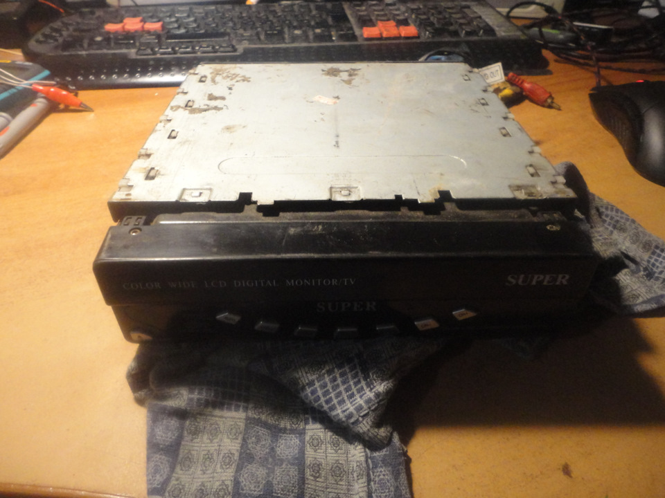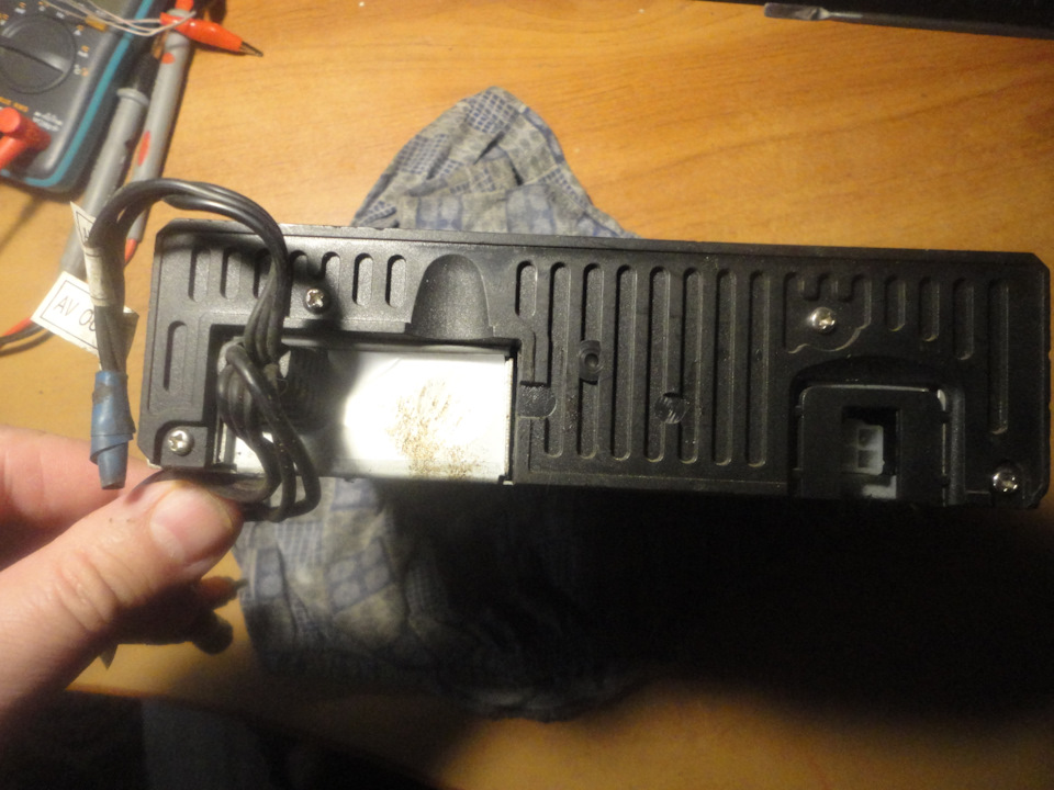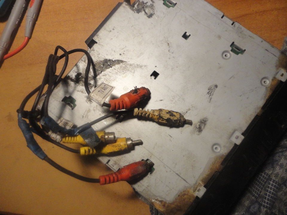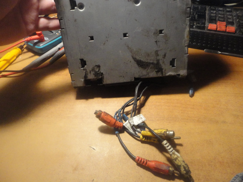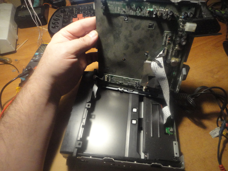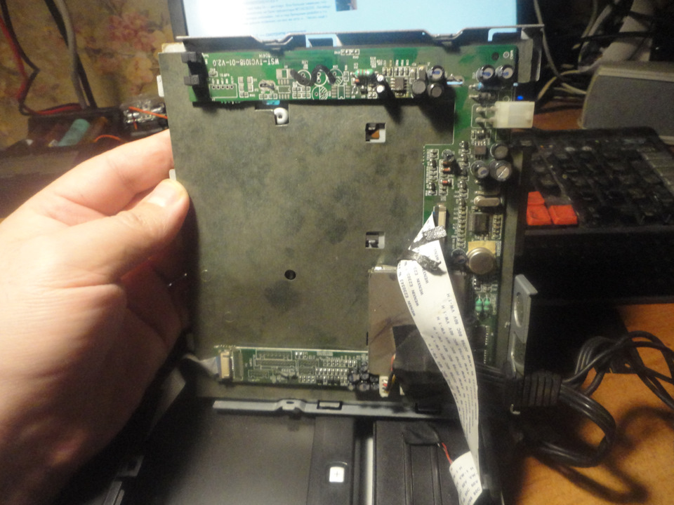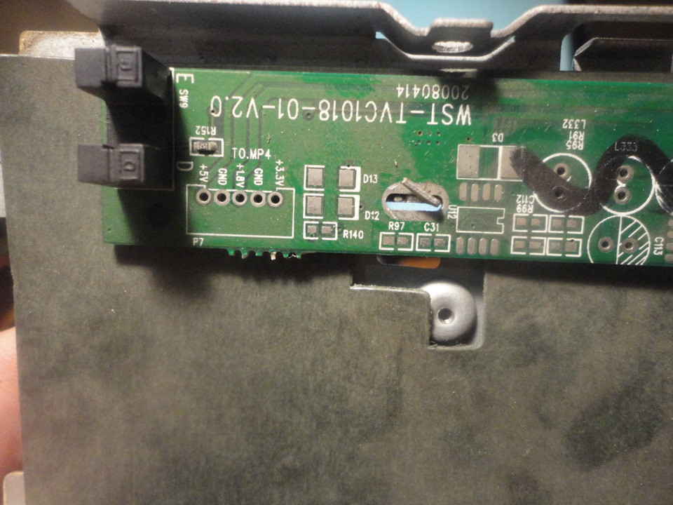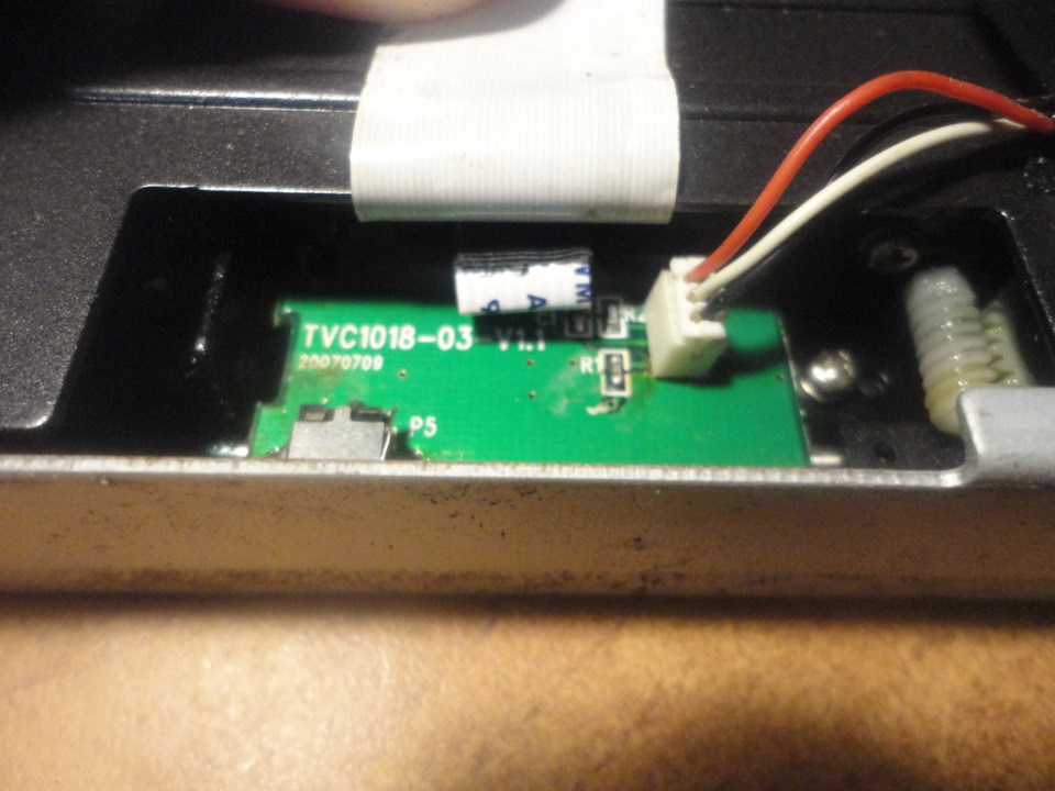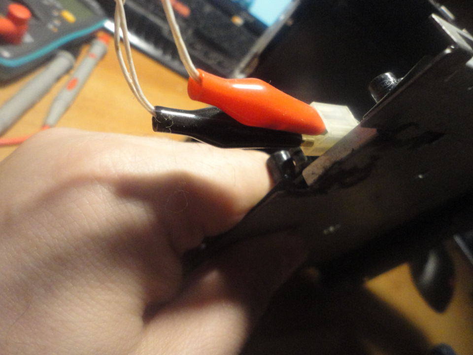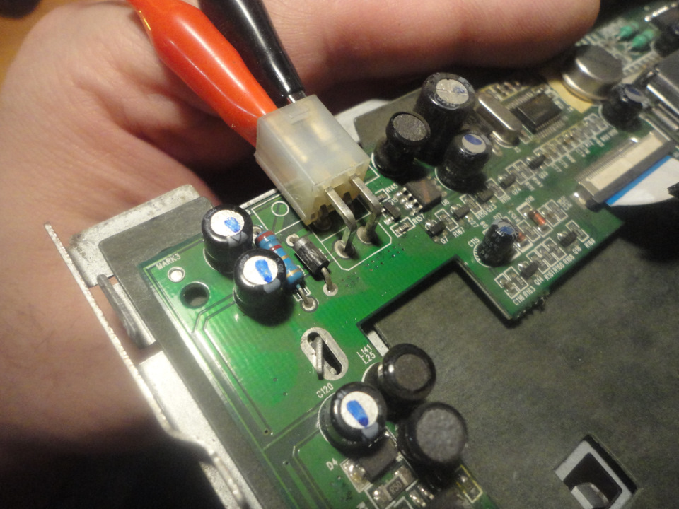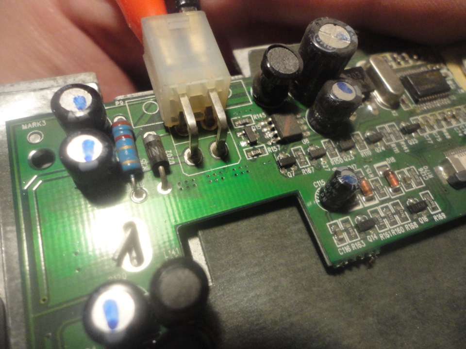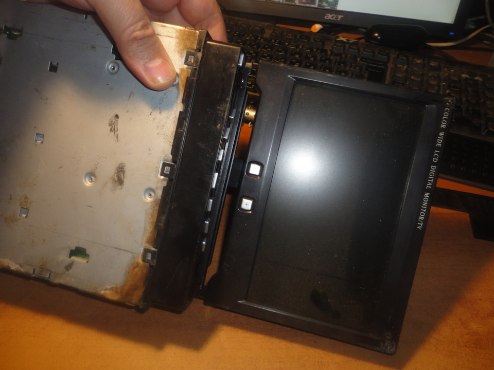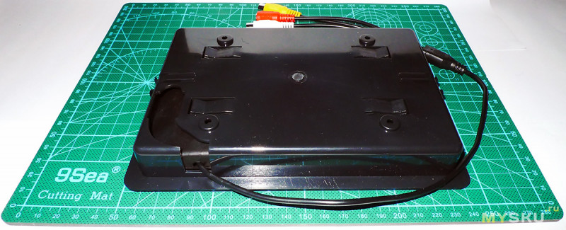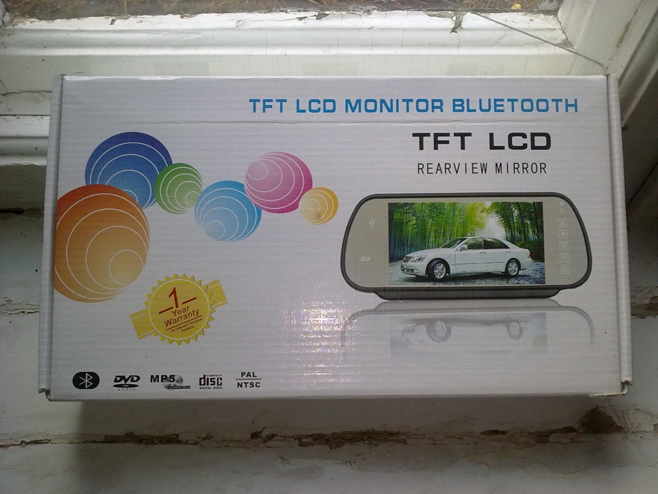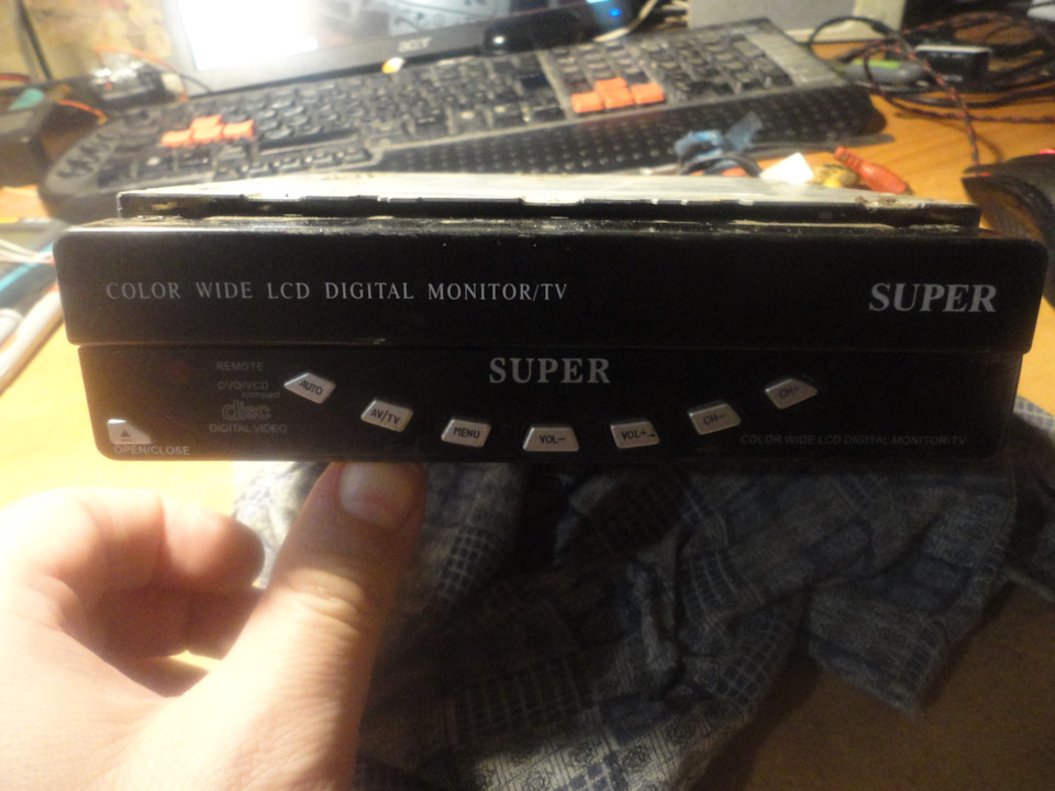
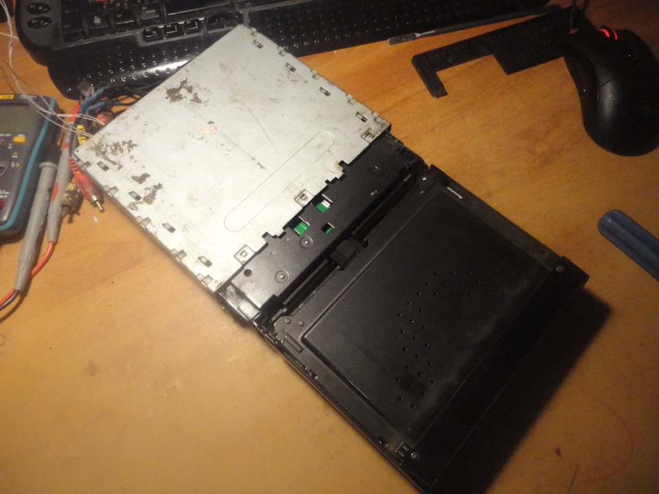
Из серии — ты ж мастер, ремонтируй.
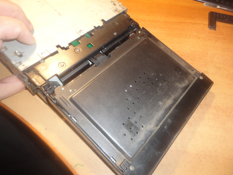
Принесли не знаю в чем, вонючее. Чем — то техническим воняет, сказали, что в гараже лежал. По моему валялся в гараже, выкинуть жалко.
Пока фоток накидаю, позже отредактирую.
Общее резюме: 7 дюймов – на мой взгляд, оптимальная диагональ для комфортного просмотра изображения с камер, но вместе с тем монитор такого размера трудно разместить в небольших машинах A и B–класса — банально мало места на торпеде. Серьезный минусом также является посредственное качество матрицы.
Если вам интересна более подробная информация – предлагаю ознакомиться с обзором.
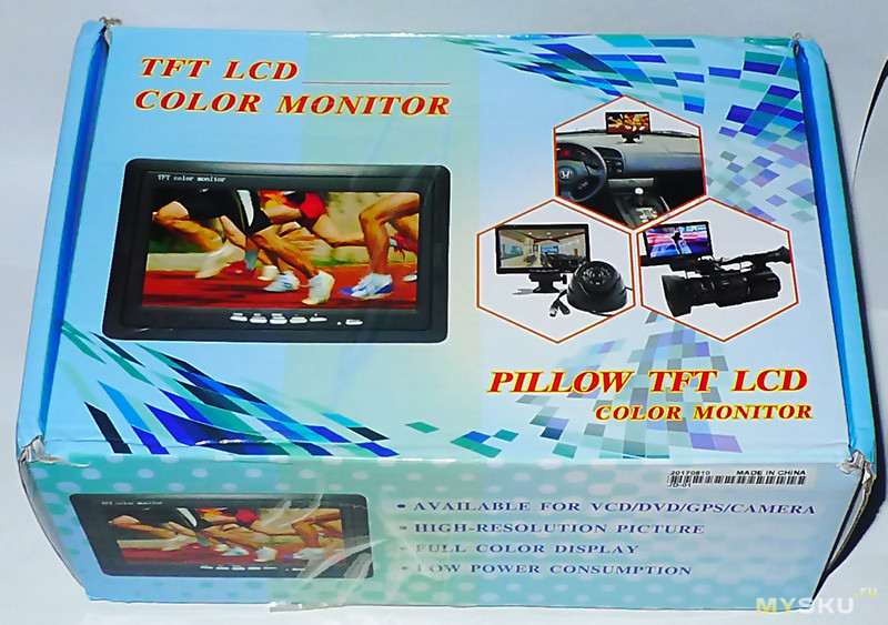
Монитор поставляется вот в такой коробке с цветным принтом:
Изображение монитора на коробке не соответствует реальному. Это, судя по всему потому, что одна и та же упаковка используется производителям для мониторов с различной конструкцией (в комплектной инструкции приведено 5 различных вариантов).
Спецификация монитора с сайта магазина также взята из инструкции и больше соответствует модели с поддержкой воспроизведения звука:
Screen size: 7”(16:9)
Display image number: 480(W)*RGB234(H),800(W)*RGB480(H)
System standard: PAL/NTSC auto switch
Workign power supply: 24V DC/12V DC optional
Power sonsumption: <5W
Video input: 75ohm 1 VP-PCCVBS
Video output: 75ohm 1VP-PCCVBS
FM launch distance: 5m
Conditions of use: temperature -30℃+60℃
Relative humidity: <90%
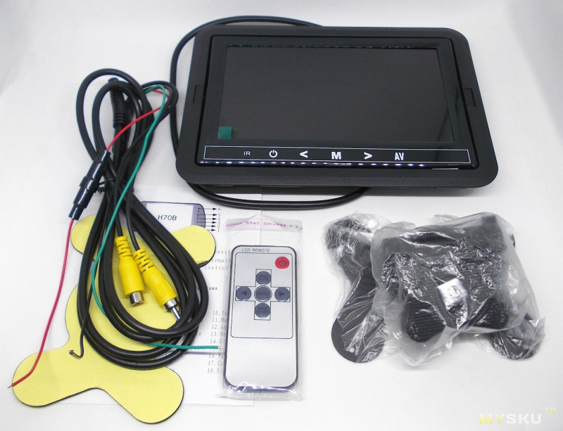
Комплект поставки включает:
- сам монитор в сборе со съемной панелью для встроенной установки,
- держатель для установки на торпеду,
- двусторонний скотч для крепления держателя,
- комплект соединительных кабелей,
- пульт,
- инструкция на английском языке.
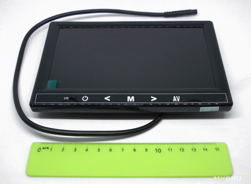
Размер монитора – 18 x 10.8 x 2.5 см (т.е. соответствуют DIN по ширине и чуть больше по высоте, что менее критично).
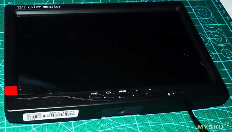
На лицевой панели внизу расположены сенсорные кнопки, со следующими функциями (слева направо):
- активация пульта,
- вкл./выкл.,
- навигация настроек влево,
- активация настроек
- навигация настроек вправо,
- переключение видеовходов.
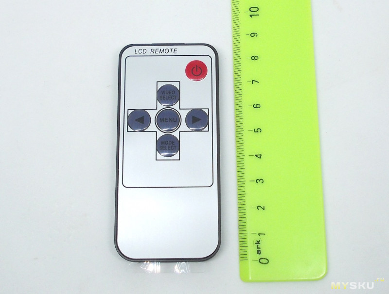
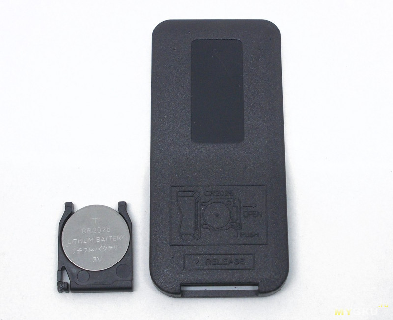
Эти же функции продублированы на комплектном миниатюрном пульте (8.5 x 4.1 x 0.5 см):
Питание пульта осуществляется от комплектной батарейки CR2025.
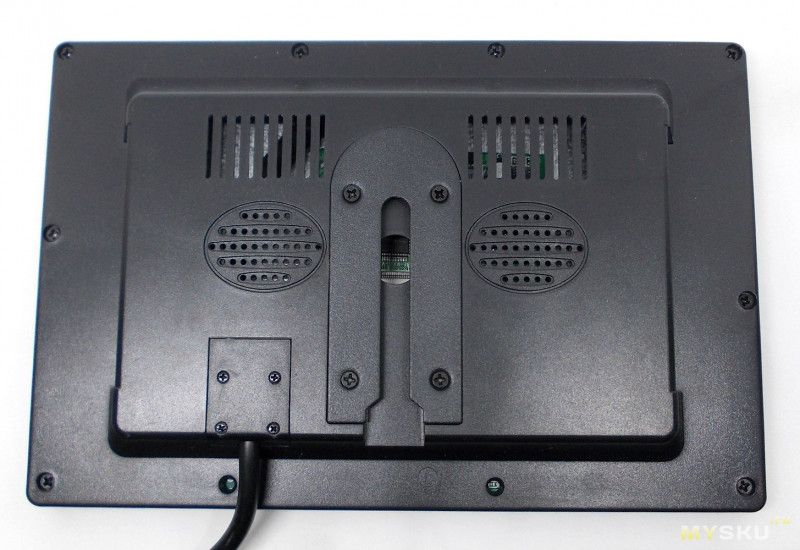
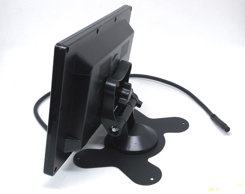
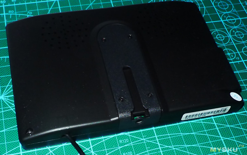
Обратная сторона. Видно крепление для подставки и вентиляционные отверстия.
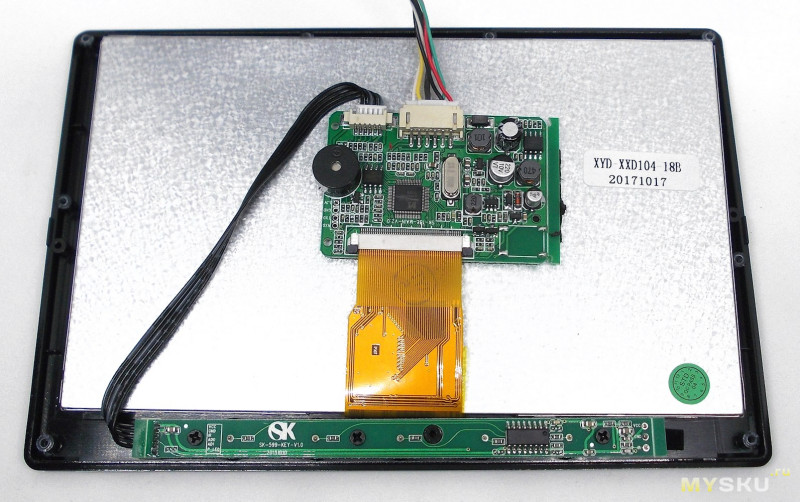
Внутренняя конструкция:
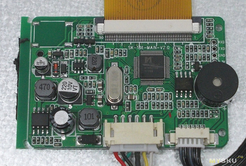
Плата управления крупным планом:
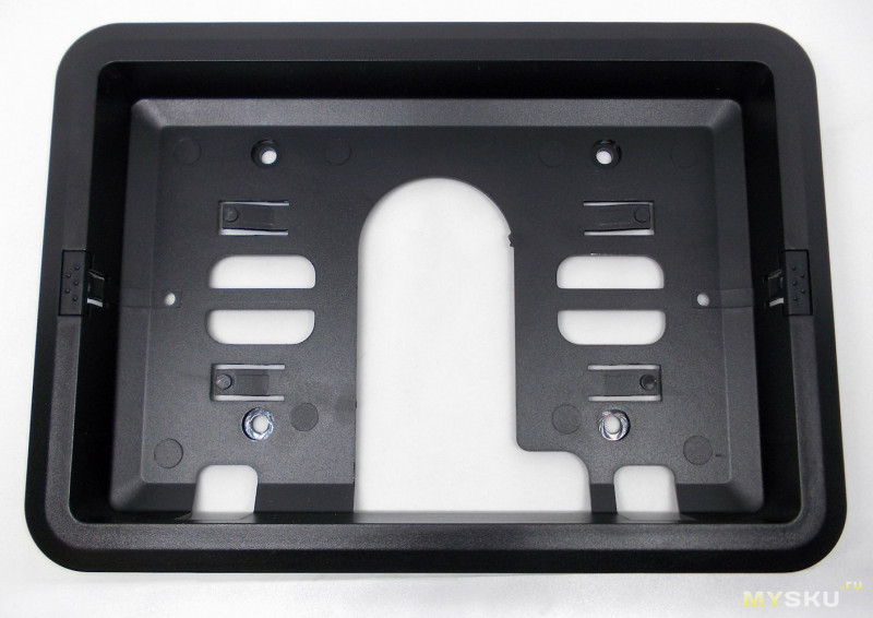
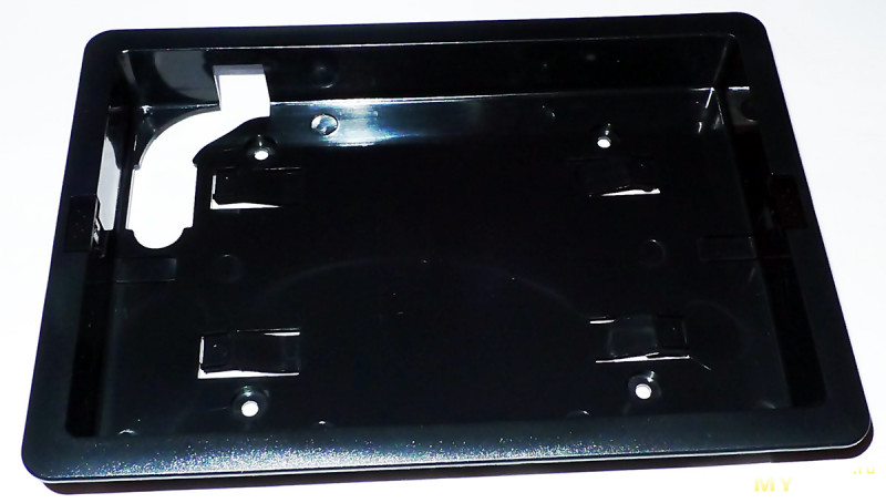
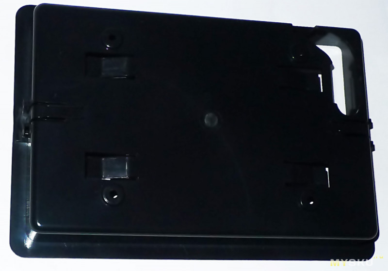
Панель для встроенного крепления:
Монитор фиксируется в панели с помощью расположенных по бокам зажимов. Для крепления самой панели предназначены четыре отверстия на задней стенке.
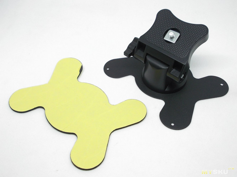
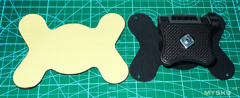
Держатель для установки на торпеду:
Крепление возможно как на двусторонний скотч или на болты/саморезы, для чего предусмотрены отверстия в подставке.
Угол наклона монитора на подставке можно регулировать.
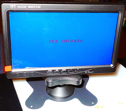
Так это смотрится в сборе:
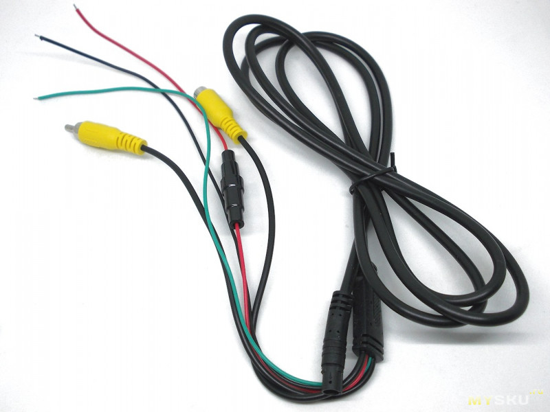
Соединительный кабель:
Красный провод – 12V, черный – заземление, зеленый – сигнал активации камеры заднего вида, RCA-разъем мама – для подключения вывода видео с регистратора, RCA-разъем папа – для подключения видео с камеры заднего вида.
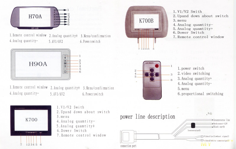
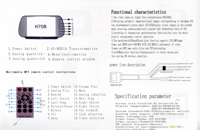
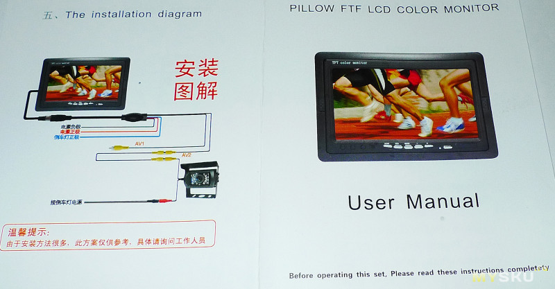
Комплектная инструкция малоинформативна, но для полноты обзора я ее все-таки приведу.
Инструкция, кому интересно
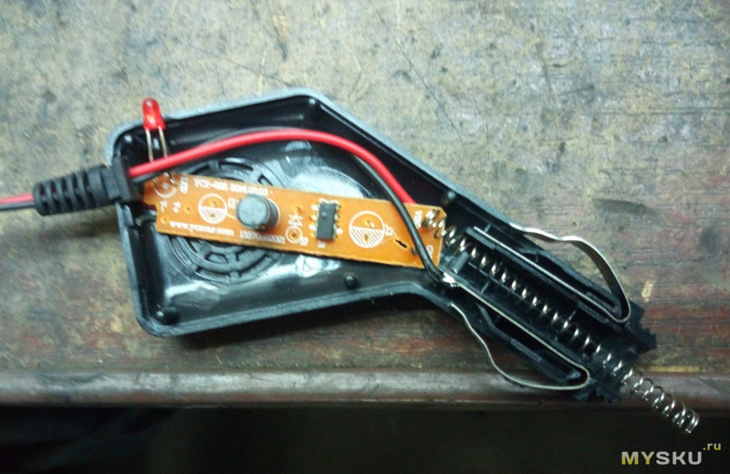
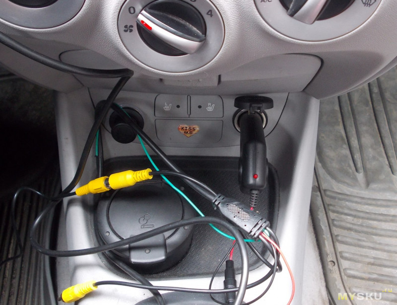
Так как камера заднего вида еще не пришла, тестирование камеры я проводил без стационарной установки. Для подключения к электросети автомобиля придумал такой переходник из сломанного зарядного в прикуриватель:
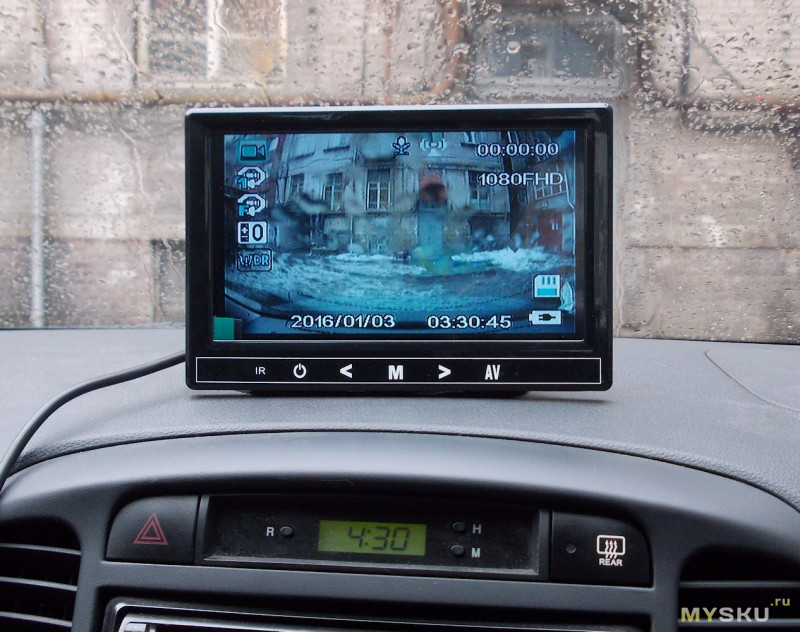
Вывод видео с регистратора:
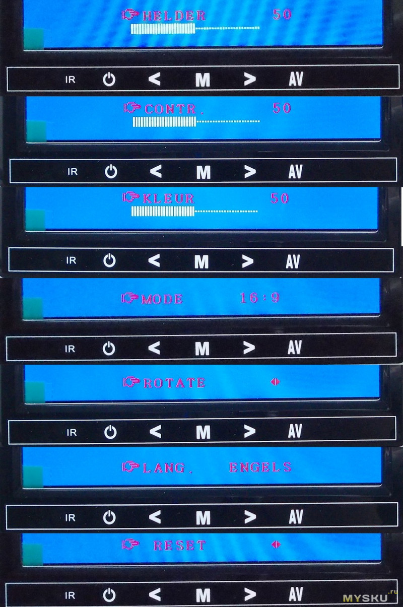
Доступные параметры настройки (для лучшей читаемости показаны на однородном фоне экрана не подключенного второго канала):
1- яркость, 2 – контрастность, 3 – цветонасыщенность, 4 – соотношение сторон (16:9 / 4:3), 5 – поворот экрана, 6 – язык (русского нет), 7 – сброс настроек.
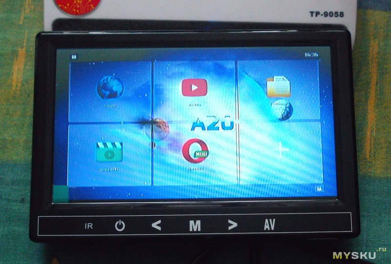
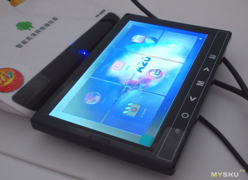
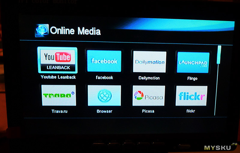
В порядке эксперимента подключил монитор к TV-box.
Как видите, картинка есть, но качество изображения оставляет желать лучшего. И дело тут не только в использовании композитного видео, но и в качестве самой матрицы, дающей инверсию цветов под острыми углами обзора.
Исходя из этого, считаю, что стоимость монитора в магазине завышена.
Товар предоставлен для написания обзора магазином. Обзор опубликован в соответствии с п.18 Правил сайта.
Предлагаю вашему вниманию обзор универсального (автомобильного) 7-дюймового TFT LCD цветного монитора с двумя видеовходами и универсальным крепежом…
Характеристики от продавца
7 Inch TFT Color LCD Dual-Input Car Monitor with Remote Controller
Description:
Color: Black
Resolution: 480 x 234(RGB)
System: PAL / NTSC
Voltage: 12V
Power:≦7 W
Operating Temperature:-20°C ~ + 50°C
Scan Frequency:2
170 degree adjustable angle.
Touching key operating.
Language: Chinese / English
Video: Two-way Video Input
7″ TFT Color LCD 16:9 Screen
Car reversing backsight surveillance.
Remote control,strong shock resistance,adjustable stand,adjustable image brightness,color and contrast.
Backlight function,automatic image switching to left or right monitoring.
Package Included:
1 x 7″ LCD Car Monitor
1 x Remote Controller
1 x Connecting Cable
1 x English User Manual
Технические характеристики:
Диагональ — 7″ 16:9
Разрешение экрана — 480 x 234(RGB)
Напряжение питания — 12В
Два видео входа
Поддержка PAL/NTSC с автоматичеким переключением.
Размеры:
Экрана (Ш/В/Г) — 170/110/20 мм
Корзины (Ш/В/Г) — 190/133/25 мм
Сам монитор весит 250гр
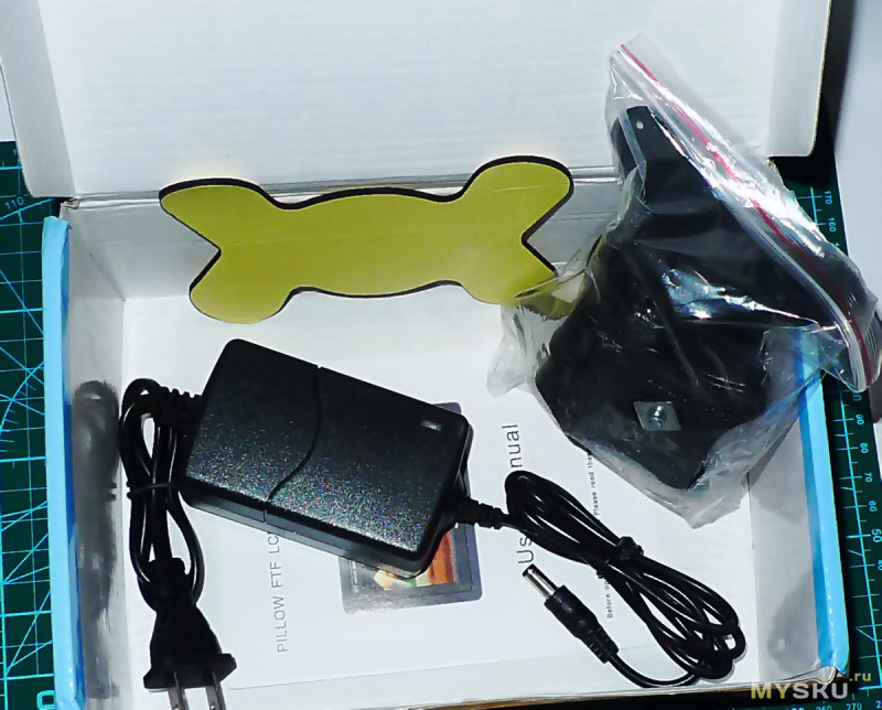
Комплект поставки в красочной картонной коробке весом 670гр что приехал ко мне:
Монитор с несъемными проводами подключения
Подставка под монитор
Корзинка для крепления корпуса монитора
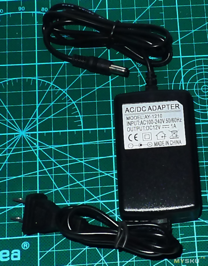
Импульсный блок питания на 12В
Инструкция
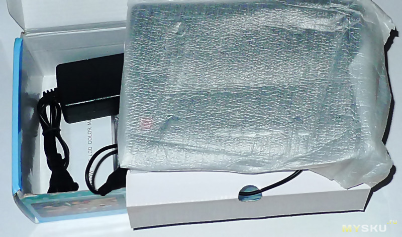
Содержимое коробки
Распаковка
Комплект поставки
Блок питания 12В
Монитор можно прикрепить к нужной поверхности двумя способами:
1. на подставке под шурупы/винты на её основании или на двухсторонний скотч который идет в комплекте.
2. через корзину которая прикручивается к нужной поверхности и далее сам монитор вставляется в эту корзину.
Монитор в корзине, вынимается из неё нажатием двух кнопок-защёлок по бокам с лицевой стороны
Вид с обратной стороны монитора помещённого в корзину
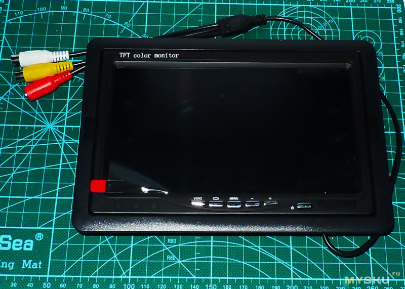
Внешне выглядит неплохо, обрамление из черного цвета матового пластика, сам экран под защитной плёнкой тоже матовый, кнопки управления хромированы.
Вид монитора с тыльной стороны
Корзина крепления монитора
С тыльной стороны
Подставка с регулируемым до 90гр углом наклона и двусторонний скотч для её неподвижного крепления
Инструкция по эксплуатации
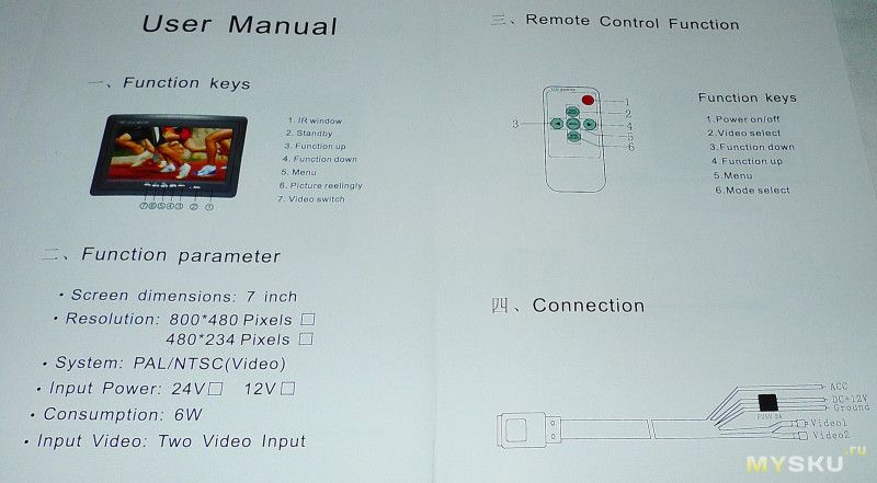
Подключение
Желтого и белого цвета гнёзда-тюльпаны это два видеовхода, красного цвета разъём DC 12В питания.
Для проверки монитора подсоединил его к медиаплееру
На панели расположено шест кнопок управления, слева — направо:
переключение видеовходов
поворот картинки
доступ к меню
кнопки +- навигации по меню
включение экрана
Меню монитора позволяет выбрать язык (есть даже русский), изменить соотношение сторон 16:9 или 4:3, изменить яркость, контрастность, насыщенность и поворот изображения.
Запас регулировки яркости, контрастности и насыщенности вполне приличный
Углы обзора по горизонтали похожи на честные 170°, по вертикали явно меньше, изображение начинает выбеливаться
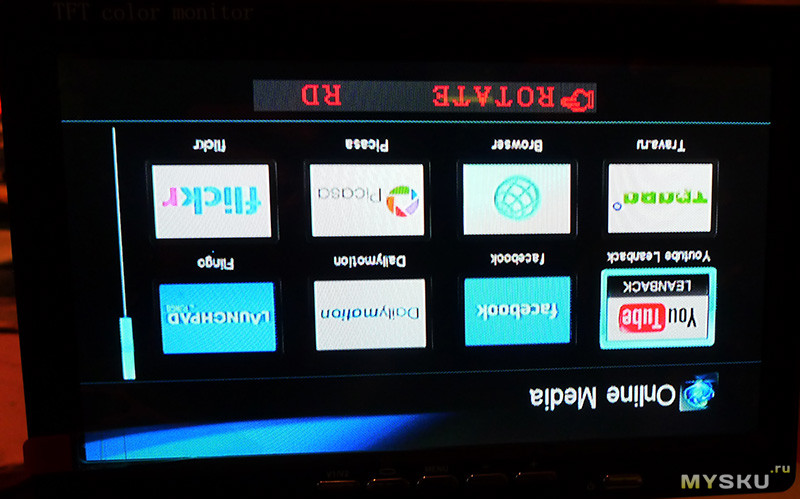
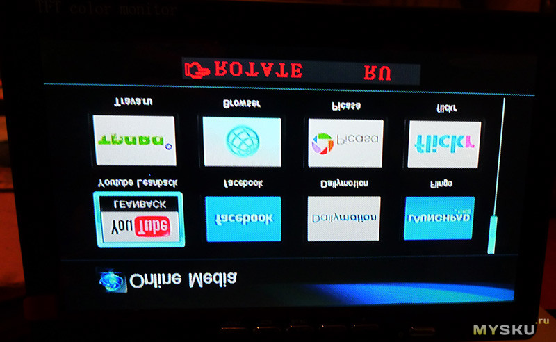
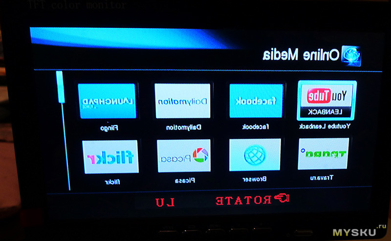
Доступные режимы поворота изображения, кнопкой на панели или через меню монитора
Итог.
Плюсы
Качество изображения вполне приличное для своей цены и предназначения, битых пикселей не обнаружил
Универсальный крепёж монитора в комплекте
Минусы.
Небольшие углы обзора по вертикали
Товар для написания обзора предоставлен магазином. Обзор опубликован в соответствии с п.18 Правил сайта.

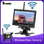
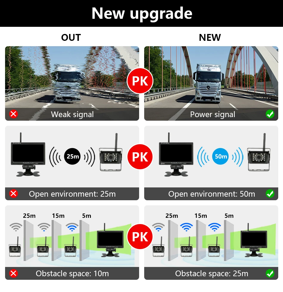
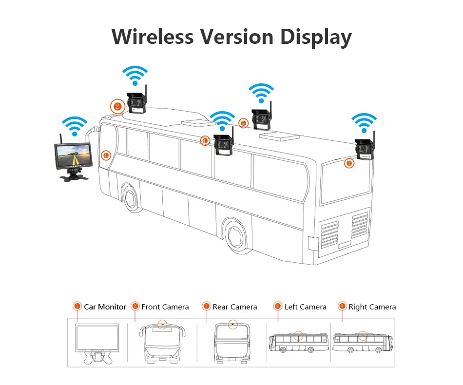
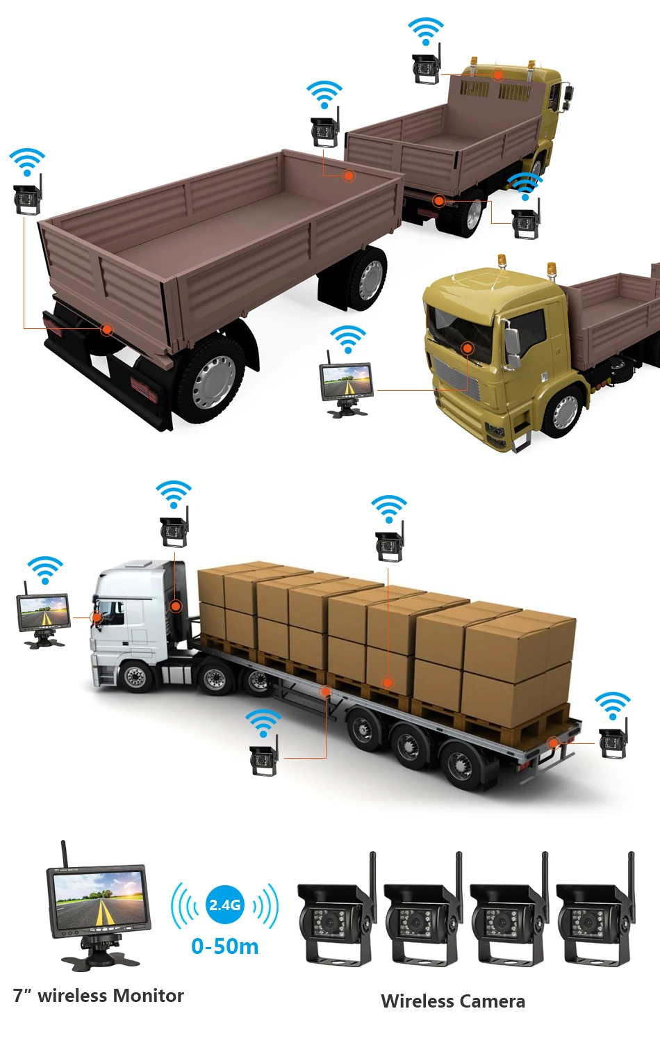
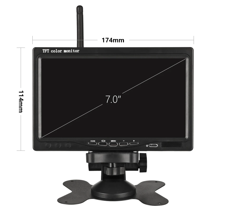
Jansite 7 дюймов беспроводной автомобильный монитор TFT LCD Автомобильная камера заднего вида HD монитор для грузовика камера для автобуса RV Ван Камера заднего вида проводная
Описание:
1,7 дюймовый HD TFT LCD широкоэкранный монитор со встроенным беспроводным приемником 2,4 ГГц
2. Заднего вида ночного видения ИК Водонепроницаемая резервная камера заднего вида с Built-in2.4GHz беспроводным передатчиком-авто водонепроницаемый объектив камеры, с 18 индивидуальными инфракрасными (ИК) светодиодами. Эффективная дальность действия: 15 м. Это поможет вам выглядеть четко ночью или в плохую погоду.
3. С 2 видеовхода-видео 1 может использоваться для обратного хода, а видео 2 может использоваться для просмотра DVD / VCD / TV / GPS.
4. Простота установки-Беспроводная помощь при парковке; Монитор запустится автоматически, и синхронно отображает видео с камеры заднего вида, когда вы поддерживаете ваш автомобиль.
5. Класс водонепроницаемости IP 67 подходит для морской среды. Жесткий металлический корпус камеры, водонепроницаемый и грязезащитный. Он может прослужить дольше без нагрева, так что вы можете показать заднего вида все время.
Спецификация:
2,4 ГГц аналоговый беспроводной 7-дюймовый монитор
Работа: 2400-2483,5 МГц
Дальность передачи: 50 метров
Формат сжатия: MPEG 4 видео
Частота передачи: 18 дБм
Скорость передачи: 12 Мбит/с
FHSS: прыгающий спектр
Скорость прыжка: 1200/с
Размер экрана: 7-дюймовый 16:9
Разрешение: 800RGB x480 точек
ТВ система: PAL / NTSC
Рабочее напряжение: 12V / 24V DC
Мощность: ≤ 8,64 Вт
Рабочая температура: от-10 градусов до + 65 градусов
Цифровая беспроводная камера 2,4 ГГц
Стандарт NTSC: 510*492 пикселей, PAL: 510*582 пикселей
Разрешение: 420 ТВЛ
Объектив: 2,5 мм
Минимальная освещенность: 0Lux (LED ON)
Инфракрасный свет: 18 шт.
Расстояние ночного видения: 15 метров
Класс водонепроницаемости: IP67
Угол обзора: 120 °
Рабочее напряжение: 12 / 24V DC
Рабочая температура: -20 °C ~ + 70 °C
Материал корпуса: алюминий
Крепление Материал: металл
7 «беспроводной HD автомобильный монитор дисплей
Беспроводные камеры/обратное изображение
На расстоянии 5 метров качество не стабильное. нужно одлиннять антены, обеспечить прямую видимость
В то, что против того, что наши производственные мощности включают в или около того только в том случае,
Брал не себе, набери в интернете, наверняка есть описание и решение проблем.
Если поставить его на фуру, то он не ловит, только для близкого расстояния
На фуре 20 метров ловит но иногда помехи!
Купи сразу комплект проводной…дешевле
Ват ис рампа?Это простая камера..без звука.
Нет, принт грузовика, автобуса, рисунок метров
Нет, это не wi fi сигнал. А просто определённая частота. 6 м через кузов помехи сильные.
На нашей работе он непрерывно работает как achteruitrijspiegel, и делает это в темноте
Камера очень хорошо работает ночью
Есть возможность подключения провода
Да, если правильно подключен
Очень рад, выглядит идеально. Устанавливается в 7-метровом доме.
Это займет около шести недель, чтобы получить мой товар.
Монитор это такое же устройство как и в компьютере, конечно же нельзя.
Покупал знакомому на фуру.Помехи говорит есть не большие…особенно если стоит под высоковольтной линией.В целом доволен покупкой.
Хорошо работает на 12 вольт системы.
Питание проводное,а так без
Он создан для детей возрастом от 12 вольт.
Не могу сказать у меня 12 вольт
Нет короче спереди и длиннее сзади) Se?
Пульт дистанционного управления ВКЛ-ВЫКЛ
По спецификациям судя — да, сможет. Брал знакомому дальнобою для установки на грузовик.
То, что нужно за шнур культивированный зарядное устройство сделано крутой камера с монитором вечный проживания
Не знаю. Выписывал не себе.
Нет, это не wi fi сигнал. А просто определённая частота. 6 м через кузов помехи сильные.
-
Applicable models
work car,bus/truck,ect
-
Feature 1
Rear view camera
-
Feature 10
Jansite car Monitor
-
Feature 5
Rear view camera monitor
-
Feature 7
monitor for car camera
-
Feature 8
wireless rear view camera
-
Feature 9
Wireless rear camera
-
Screen Resolution
800*480
-
Wireless connections
Wireless Kit
-
Материал объектива
Пластик
-
Минимальная единица измерения
100000015
-
Размер логистики — высота (см)
10
-
Размер логистики — длина (см)
26
-
Размер логистики — ширина (см)
24
-
Сертификация
Европейский сертификат соответствия
-
Способ подключения
Проволока
-
Тип материала
АБС-пластик
-
Тип сигнализации
Видеокамера заднего вида в автомобиле
4ARLIK
Был больше месяца назад
Привет всем! вот прикупил еще один ништячок, монитор зеркало 7 дюймов, подключается к AV выходу магнитолы, в комплекте пульт ДУ, теперь смотреть фильмы могут все пассажиры Passat-a.
Удачи на дорогах!
Цена вопроса: 4 300 ₽
Пробег: 223 000 км
Машины в продаже
Комментарии
18
Войдите или зарегистрируйтесь, чтобы писать комментарии, задавать вопросы и участвовать в обсуждении.
DanDangerous, нашел проблему с автопереключением?
Включается ли картинка заднего вида на мониторе при включении заднего хода?
Камеры у меня небыло, но в инструкции сказано что при правильном подключении все должно работать.
Вроде все правильно собрал, перечитал кучу инструкций, выслушал множество советов спецов! не хочет работать автоматически! при каждом включении заднего хода приходится включать монитор!
у меня магнитола не штатная sony, выходы есть, но штейкер один подходит, а другой нет((не знаю что делать!
Дружище, подскажи пожалуйста как к магнитоле цеплял!в какие гнезда?или что переделывал?
Ничего, не переделывал, стыковал стандартным тюльпаном на аудио и AV выходы.
а как зеркало заднего вида он как? можешь сфоткать в нерабочем состоянии?
как зеркало нормально, сфоткать неполучится на фото как обычный экран.
если монитор выключить он будет как зеркало? или просто черный экран?
когда выкл.как тонированное зеркало.
а как в него видно? нормально или мутно?
видно нормально, только привыкать надо.
Подскажите пожалуйста как подключить телефон по Bluetooth.
Требует пароль 1234, 123, 0000, 000.
Не подходит
У меня 1234 подходит, сделай сброс RESET, на магнитоле.
Все комментарии
-
Contents
-
Table of Contents
-
Bookmarks
Quick Links
Thank you for purchasing our product.
Please read this User’s Manual before
using the
product.
Change without Notice
7″ TFT LCD MONITOR
USER MANUAL
e
-4
1
Related Manuals for Aaeon 7” TFT LCD MONITOR
Summary of Contents for Aaeon 7” TFT LCD MONITOR
- Page 1
Thank you for purchasing our product. Please read this User’s Manual before using the product. Change without Notice 7” TFT LCD MONITOR USER MANUAL… -
Page 2: Safety Precaution
Safety Precautions Federal Communications Commission (FCC) Statement This Equipment has been tested and found to comply with the limits for a Class B digital device, pursuant to Part 15 of the FCC rules. These limits are designed to provide reasonable protection against harmful interference in a residential installation.
-
Page 3: Table Of Contents
Content Table Safety Precaution.……..……………………………………………………………… 2 Content Table….….…………………………………………………………………… 3 Feature….……………………………………………………………………………… 4 1. Package Contents…….…………………………………………………………. 5 2. TFT Installation…………………………………………………………………… 6 3. Signal Cable Description……..…………………………………………………. 7 4. Control Cable Description……..………………………………………………… 9 5. Front Panel Control.……………………………………………………………… 10 OSD Menu ………………………..…..………………………………………….. 11 Picture…..………………………………………………………………….………. 12 Function…………………………………………………………………………… 13 Recall……………………………………………………………………………….
-
Page 4: Feature
Feature Support up to 2 CCD Camera Inputs (Mini din Connector) Extra RCA Input for Multimedia (VCD, DVD, Game Device) Provide 1 Video / 1 Audio Signal Output Auto Detection for NTSC / PAL System Support Trigger : 3 (Back / Door / AV) Auto Brightness Adjustment by CDS Back Mirror Status Selection via OSD Video Output Select via OSD (Back / Door / AV)
-
Page 5: Package Contents
1. Package Contents Item Qty. 1. 7” LCD Monitor 2. Sun-hood 3. Mounting Bracket 4. Accessories 5. Control Cable 6. User Manual…
-
Page 6: Tft Installation
2. TFT Installation Step 1 Check the package and make sure all parts are included Step 2 Clip the sun-hood on to the monitor Step 3 Make sure it is installed properly Step 4 Install the monitor on to the bracket Step 5 Adjust the monitor to an appropriate / comfortable viewing angle before tightening the screws…
-
Page 7: Signal Cable Description
3. Signal Cable Description BACK DOOR AV VID EO IN Gr ay co lor lin e LIV E V IDEO OU T Whit e col o r li ne LIVE AU DI O O UT Blac k co lo r li ne AV AU DIO I N Re d color l ine 1.
- Page 8
Mini Din Pin Assignment * Type 1 (Standard): 1. —— 4. GND 2. —— 5. +12V 3. Audio 6. Video (Optional) *Type 2 1. GND 4. +12V 2. —— 5. ——- 3. Video 6. Audio… -
Page 9: Control Cable Description
4. Control cable Description WH IT E ( DOOR .,e tc) 6 BL ACK ( GND ) Fuse 5A B LU E (R EVE R S E) 2 Re d OR AN GE C OL OR 4 RE D (AC C POWE R) 1.
-
Page 10: Front Panel Control
5. Front Panel Control POWER Press the power button to activate the monitor or to keep the monitor under stand by mode. Red light for stand by, Green light is turn on. SOURCE Press this button to select Back or Door image, it can select AV / BACK / DOOR image when the hand park is working.
-
Page 11: Osd Menu
OSD MENU 1. Press the MENU button to enter to the OSD Menu 2. Turn the MENU button left or right to select the setting you wish to proceed. The color of the content will turn YELLOW to identify your selection. 3.
-
Page 12: Picture
PICTURE The PICTURE set up contains different setting for the TFT: BRIGHTN ESS CON TRAST COL OR HU E CAMER A TIMER STEP VIDEO TIMER STEP RETUR N Menu Ju m p S ou rce P ower BRIGHTNESS Provide adjustment for the overall picture shade and brightness of TFT display.
-
Page 13: Function
FUNCTION The FUNCTION set up contains the on screen identification and the activation of the distance gage. BAC K MIRROR STATUS DISTANCE GAGE VIDEO OU T SEL EC T AUTO BRIGH T AD JU ST RETUR N Menu Ju mp S ourc e P o wer BACK MIRROR STATUS…
-
Page 14: Vehicle Installation
6. Vehicle Installation Camera Yellow Green a. Install Camera R (for rear view) b. Use a measuring tool to mark out the distance behind the vehicle. c. Adjust the viewing angle of the camera so that the distance gage shown from the TFT match to the distance marks behind the vehicle.
-
Page 15: Specification
7. Specification Screen size 7 inch ( diagonal ) Active area 154.08(W) x 86.58(H) Pixel configuration 0.107(W) x 0.370(H) Resolution 1440(W) x 234 (H) Viewing angle UP:60° / Down:60° / Left: 60° / Right:60° Power source: DC9.6V ~DC32V Contrast ratio 300:1 Brightness 400 cd/m…
-
Page 16: Attachment
8. Attachment Attachment 1: Dimension Chart…
|
Новичок Регистрация: 19.03.2012 Сообщений: 15 Репутация: 11
|
Упал не включается. Не подает не каких признаков. Напряжения питания микросхем присутствуют. Видимых повреждений сколов,трещин нет. Помогите найти схему. |
|
|
|
В электронном оборудовании железнодорожного транспорта востребованы DC/DC-преобразователи, которые соответствуют определенным отраслевым стандартам (EN50155, EN50121, EN45545-2, EN61373). В этих нормативных документах содержатся практически все необходимые требования к компонентам, применяемым в ЖД-оборудовании. Широкий выбор DC/DC-преобразователей для ЖД-транспорта имеется в номенклатуре известного производителя MORNSUN. В настоящий момент продукция этой компании широко представлена на российском рынке и доступна как со склада, так и под заказ с небольшим сроком поставки. |
|
Эксперт Регистрация: 26.12.2010 Адрес: Санкт-Петербург Сообщений: 2,643 Репутация: 953
|
Смотри здесь: |
|
|
|
Компания MEAN WELL разработала две серии многофункциональных интеллектуальных источников бесперебойного питания на DIN-рейку – DRS-240 и DRS-480 – с выходной мощностью 240 и 480 Вт. Новые ИБП сочетают в одном корпусе AC/DC-источник питания, контроллер заряда/разряда АКБ и контроллер управления и мониторинга с возможностью программирования. Новые ИБП уже представлены в Компэл и предназначены для охранных и противопожарных систем, оборудования для экстренной связи, аварийного освещения и центральных систем мониторинга. |
|
Новичок Регистрация: 19.03.2012 Сообщений: 15 Репутация: 11
|
Там уже был. Есть только фото похожее и все, а схемы к фото нет. |
|
|

|
Опубликованы материалы вебинара, посвященного подходу компании MEAN WELL к созданию мощных управляемых систем низковольтного и высоковольтного питания и зарядных установок для промышленного, технологического, телекоммуникационного, медицинского, радиопередающего и другого оборудования, а также для систем альтернативной энергетики. На вебинаре мы рассмотрели новинки и серийную продукцию в концепции «3+N», расскажем об этой концепции и о том, как создать из готовых модулей систему питания мощностью до 360 кВт с напряжением до 380…400 В (постоянного тока). Были представлены ИП с рециркуляцией энергии для тестового оборудования и модули управления питанием. |
|
Гуру Регистрация: 10.11.2011 Адрес: Taganrog |
Что и звука нет?Схемы не найдешь -чистый кит.это с ДВД?Фото платы прикрепил бы..Так что рой напруги промежуточные-5В и 3.3В…Опиши состав.Падалец это грустно-на инверторе есть напруги?… |
|
|
|
Эксперт Регистрация: 26.12.2010 Адрес: Санкт-Петербург Сообщений: 2,643 Репутация: 953
|
Возьми любую схему, похожую по составу, и работай. Что при падении могло случиться? Лампа, кварц, трещина какая-нибудь, исходи из этого. Вот у меня от какого-то Super схема безымянная. |
|
|
|
Новичок Регистрация: 19.03.2012 Сообщений: 15 Репутация: 11
|
Огромное спасибо! Запустил. -вышел из строя кварц. |
|
|
C:Documents and SettingskenjiDesktopWork4-159-460 Pepper11(1)
EN41594601114159460111_Pepper EN_EN0USBCO.fm
Online
Reference
Book:
Online
Registration:
Software
Updates:
For Your Convenience
To learn more about your unit, visit the online Reference Book at: http://www.sony.com/referencebook
Be sure to register your unit.
United States
Canada
http://productregistration.sony.com
http://www.SonyStyle.ca/registration
Your unit is capable of receiving software updates. For the latest information about software updates for your unit, visit:
United States
Canada
http://www.sony.com/tvsupport http://www.sony.ca/support
NOTE: If your unit is connected to the Internet, you can check for software updates by selecting
Settings, Product
Support and then Software Update.
masterpage:Left
C:Documents and SettingskenjiDesktopWork4-159-460 Pepper11(1)
EN41594601114159460111_Pepper EN_EN0USCOVER.fm
LCD Digital
Color TV
masterpage:Right
Printed in Japan
4-159-46011(1)
KDL-46XBR10/KDL-52XBR10
4-159-460-
11(1)
KDL-52XBR10
KDL-46XBR10
MBT-WZ5
© 2009 Sony Corporation
Sony Customer Support
U.S.A.: www.sony.com/tvsupport
Canada: www.sony.ca/support
United States
1.800.222.SONY
Canada
1.877.899.SONY
Please Do Not Return the Product to the Store
KDL-46XBR10/KDL-52XBR10
4-159-460-
11(1)
Owner’s Record
The model, electric ratings, serial numbers and the date of manufacture are in the following locations:
Monitor: rear of the monitor at the bottom left
Media receiver: on the underside and rear
Record these numbers in the spaces provided below. Refer to them whenever you call upon your Sony dealer regarding this unit.
Monitor
Model Name
Serial No.
Media receiver
Model Name
Serial No.
CAUTION
To prevent electric shock and blade exposure, do not use this polarized AC plug with an extension cord, receptacle or other outlet unless the blades can be fully inserted.
❑
Operate the unit only on 120 V AC.
❑
Avoid operating the unit at temperatures below 41°F (5°C).
Wireless Function of the Unit
❑
The picture may be affected depending on the installation environment or setup of the monitor and media receiver
(page 20).
❑
It may take time to transmit pictures depending on the types of signal, fast motion, such as game pictures, etc.
❑
If pictures from a PC or still images are displayed, flickering or blurring may occur.
❑
This unit can be used only in combination of the supplied monitor and media receiver.
❑
Do not operate this unit near medical equipment (pacemaker, etc.), as malfunction of the medical equipment may result.
❑
Although this unit transmits/receives scrambled signals, be careful of unauthorised interception. We cannot be responsible for any trouble as a result.
Licensing Information
Macintosh is a trademark of Apple Inc., registered in the U.S. and other countries.
HDMI, the HDMI logo and High-Definition Multimedia Interface are trademarks or registered trademarks of HDMI Licensing, LLC.
Fergason Patent Properties, LLC:
U.S. Patent No. 5,717,422
U.S. Patent No. 6,816,141
Manufactured under license from Dolby Laboratories. Dolby and the double-D symbol are trademarks of Dolby Laboratories.
In the United States, TV Guide and other related marks are trademarks of Gemstar-TV Guide International, Inc. and/or its subsidiaries. In Canada, TV Guide is a registered mark of
Transcontinental Inc., and is used under license by Gemstar-TV
Guide International, Inc. and/or its subsidiaries.
The TV Guide On Screen system is manufactured under license from Gemstar-TV Guide International, Inc. and/or its subsidiaries.
The TV Guide On Screen system is protected by one or more of the following United States patents 6,498,895; 6,850,693; 6,396,546;
5,940,073; 6,239,794 to Gemstar-TV Guide International, Inc. and/ or its subsidiaries.
Gemstar-TV Guide International, Inc. and/or its related affiliates are not in any way liable for the accuracy or availability of the program schedule information or other data in the TV Guide On Screen system and cannot guarantee service availability in your area. In no event shall Gemstar-TV Guide International, Inc. and/or its related affiliates be liable for any damages in connection with the accuracy or availability of the program schedule information or other data in the TV Guide On Screen system.
Blu-ray Disc is a trademark.
“BRAVIA” and and DMe x
, S-Force, Motionflow, BRAVIA Sync,
are trademarks or registered marks of Sony Corporation.
“XrossMediaBar” is a trademark of Sony Corporation. “XMB” is a trademark of Sony Corporation and Sony Computer Entertainment
Inc.
“PlayStation” is a registered trademark and “PS3” is a trademark of
Sony Computer Entertainment Inc.
DLNA
®
, the DLNA Logo and DLNA CERTIFIED™ are trademarks, service marks, or certification marks of the Digital
Living Network Alliance.
Your BRAVIA TV is ENERGY STAR ® qualified in the “Home” mode.
It meets strict energy efficiency guidelines set by the U.S. Environmental Protection Agency and
Department of Energy. ENERGY STAR is a joint program of these government agencies, designed to promote energy efficient products and practices.
Changes to certain features, settings, and functionalities of this TV
(i.e. TV Guide, Picture/Sound, Light Sensor, Power Savings) can increase or change the power consumption.
Depending upon such changed settings, the power consumption may exceed the limits required for the ENERGY STAR qualification in the “Home” mode.
2
This manual is for the 46 and 52 inch BRAVIA KDL-XBR10 series models with screen size measured diagonally.
Contents
Introducing Your BRAVIA
®
TV
Experiencing Stunning HD with
Your BRAVIA TV . . . . . . . . . . . . . . . . . . . . . 4
The Four Steps to a Full HD Experience . . . . 4
TV Feature Highlights . . . . . . . . . . . . . . . . . . . 5
Getting Started
Setting Up Your Monitor . . . . . . . . . . . . . . . . . 6
Connecting the AC Power Cord . . . . . . . . . . . 7
Using a Wall-Mount Bracket . . . . . . . . . . . . . .8
Locating Inputs and Outputs . . . . . . . . . . . . . 10
Connecting the Unit . . . . . . . . . . . . . . . . . . . 12
Connecting Internet & DLNA Certified™
Networks. . . . . . . . . . . . . . . . . . . . . . . . . . . 15
Connecting Other Equipment . . . . . . . . . . . . 16
Removing the Terminal Cover for
Monitor . . . . . . . . . . . . . . . . . . . . . . . . . . . . 17
Installing the Unit Against a Wall or
Enclosed Area . . . . . . . . . . . . . . . . . . . . . . 17
Securing the Monitor . . . . . . . . . . . . . . . . . . . 18
Establishing the Wireless Communication
Between the Monitor and
Media Receiver. . . . . . . . . . . . . . . . . . . . . . 20
Running Initial Setup . . . . . . . . . . . . . . . . . . . 21
Operating the TV
Using the Remote Control. . . . . . . . . . . . . . . 22
Remote Control Button Description . . . . . . . 23
Unit Controls and Indicators . . . . . . . . . . . . . 26
Programming the Remote Control . . . . . . . . 27
Manufacturer’s Code List . . . . . . . . . . . . . . . 28
Using Other Equipment with Your
Remote Control. . . . . . . . . . . . . . . . . . . . . . 30
Remote Control Backlight . . . . . . . . . . . . . . . 31
Exploring the XMB
™
Features
and TV
Category Icons . . . . . . . . . . . . . . . . . . . . . . . 33
Accessing Photo, Music, and Video
Content . . . . . . . . . . . . . . . . . . . . . . . . . . . . 34
BRAVIA Internet Video . . . . . . . . . . . . . . . . . 35
Photo, Music, and Video . . . . . . . . . . . . . . . . 36
BRAVIA Internet Widgets . . . . . . . . . . . . . . . 39
Favorites . . . . . . . . . . . . . . . . . . . . . . . . . . . . 41
TV Guide On Screen
®
. . . . . . . . . . . . . . . . . 42
Background TV . . . . . . . . . . . . . . . . . . . . . . . 44
Inputs . . . . . . . . . . . . . . . . . . . . . . . . . . . . . . 44
Wide Mode . . . . . . . . . . . . . . . . . . . . . . . . . . 45
BRAVIA
®
Sync™ with Control for HDMI. . . . 47
Other Information
How to Care for Your BRAVIA . . . . . . . . . . . 48
Troubleshooting . . . . . . . . . . . . . . . . . . . . . . 48
Specifications . . . . . . . . . . . . . . . . . . . . . . . . 50
Index . . . . . . . . . . . . . . . . . . . . . . . . . . . . . . . 52
Welcome to the World of BRAVIA
®
HDTV
Thank you for purchasing this Sony BRAVIA
®
high-definition television. Use the documentation listed below to get the most out of your unit.
Safety Booklet
Provides precautionary measures to keep you and your unit safe. Read this information prior to setting up your unit.
Operating Instructions
Provides general unit operation information.
Quick Setup Guide
Provides unit setup information, illustrates sample optional equipment connection diagrams, and highlights TV features.
Reference Book
Offers the most complete unit operation information available for your unit and presents advanced customization details. Access it at www.sony.com/referencebook.
The unit operation information above has been designed in an eco-friendly manner to reduce the consumption of natural resources.
3
Introducing Your BRAVIA
®
TV
Experiencing Stunning HD with Your BRAVIA TV
To experience the stunning detail of your new BRAVIA TV, you need access to high-definition
(HD) programming. Your BRAVIA TV can receive and display HD programming from:
• Over-the-air broadcasting via HD-quality antenna
• HD cable subscription
• HD satellite subscription
• Blu-ray Disc™ player or other HD compatible external equipment
Contact your cable, satellite or HD service provider for information on upgrading to HD programming.
The Four Steps to a Full HD Experience
Set, Source, Sound, and Setup
Along with your BRAVIA TV set, a complete HD system requires a source of HD programming, an HD sound system, and a proper connection setup. Refer to the Quick
Setup Guide, enclosed separately, for connecting other optional equipment.
You can enjoy crisp, clear images, smooth movement, and high-impact visuals from
1080 HD signals as shown here.
When you compare a high-definition signal to a standard definition signal, you will notice a big difference in picture quality. If black bars appear as shown here, press WIDE on the remote control to fill the screen.
4
TV Feature Highlights
Your BRAVIA TV is equipped with the latest in TV technology.
➢ Broadband Internet Connectivity: BRAVIA Internet
Video brings videos, movies and much more from the
Internet to your unit (page 35). BRAVIA Internet Widgets
allow you to access local weather, news, and much more.
Displayed here is Widgets (page 39).
➢ Digital Media Accessibility: Use the Photo, Music, and
Video Category icons to access photo, music, and video files from DLNA Certified
TM
networked equipment or Sony
USB equipment. Displayed here is Photo USB (page 36).
Photo
DSC02991
Fri 5/25/2007 12:06 PM JPG
DSC00140.JPG
DSC00141.JPG
➢ Central Location for Your Favorite Items: The
Favorites feature centralizes your favorite BRAVIA
Internet Video and Widgets items, Photo, Music, Video content, TV channels, External Inputs, and Background
TV themes for quick and easy access (page 41).
➢ Channel Programming Information: TV Guide On
Screen
®
provides TV programming information (page 42).
➢ TV Home Menu: XMB
TM
(XrossMediaBar) unit menu provides you access to unit settings, photo, music, video,
TV channel listings, and more (page 32).
Product Support
Preferences
Settings
Picture & Display
Sound
Channels & Inputs
Network
TV
5
Getting Started
Setting Up Your Monitor
This monitor is packaged with a detached Table-Top Stand so you can mount your monitor to a wall right away. If you are not mounting the monitor to a wall, you will need to attach the Table-
Top Stand. You will need a Phillips screwdriver and the supplied screws to complete the task. Look for the attachment instructions provided with the unit.
Be sure to consider the following while setting up your monitor:
• Disconnect all cables when carrying the monitor.
• Carry the monitor with the adequate number of people; larger size monitors require two or more people.
• Correct hand placement while carrying the monitor is very important for safety and to avoid damage.
• Ensure your monitor has adequate ventilation, see page 17.
• For best picture quality, do not expose the screen to direct illumination or sunlight.
• Avoid installing the monitor in a room with reflective wall and floor materials.
• Avoid moving the monitor from a cold area to a warm area. Sudden room temperature changes may cause moisture condensation. This may cause the monitor to show poor picture and/or poor color. Should this occur, allow moisture to evaporate completely before powering the monitor on.
6
• Read the supplied Safety Booklet for additional safety information.
• When cable connection is completed, be sure to secure the monitor to a stable surface or mount it to a wall. The designated Sony wall-mount bracket model and TV stand model name(s) are available under the “Other Information” section of Operating Instructions. For details on securing
the monitor, see page 18.
Connecting the AC Power Cord
Make sure all connections are set before connecting the AC power cord.
Monitor
1
Connect the supplied AC power cord to the monitor.
2
Attach the stand cover.
Do not pinch the AC power cord.
3
Attach the terminal cover.
4
Media receiver
AC power cord (supplied)
7
Using a Wall-Mount Bracket
All models can be mounted to a wall using the Wall-Mount Bracket (not supplied) out of the box as packaged.
Prepare the monitor for the Wall-Mount Bracket before making cable connections.
Sony strongly recommends that you use the Wall-Mount Bracket model designed for your
monitor (see page 49) and that wall-mounting of your monitor should be performed by a
Sony dealer or licensed contractor.
• Follow the instruction guide provided with the Wall-Mount Bracket for your model. You may also need to refer to the online Reference Book for additional information for your unit model. Sufficient expertise is required in installing this monitor, especially to determine the strength of the wall for withstanding the monitor’s weight.
• Be sure to use the screws supplied with the Wall-Mount Bracket when attaching the mounting hooks to the monitor. (Do not use the screws that are intended for the Table-Top
Stand attachment.)
The supplied M6 screws are designed so that they are 8 mm to 12 mm in length when measured from the attaching surface of the mounting hook.
Use of screws other than those supplied with the bracket may result in internal damage to the monitor or cause it to fall, etc.
When attaching to the Wall-Mount Bracket
8-12 mm
Spacer (black)
Screw M6 × 16 (supplied with the Wall-Mount Bracket)
Mounting Hook
Rear of the monitor
When attaching to the Floor Stand
8-12 mm
Spacer (silver)
Screw M6 × 20 (supplied with the monitor)
Mounting Hook
Rear of the monitor
• Be sure to store the unused screws and Table-Top Stand in a safe place until you are ready to attach the Table-Top Stand. Keep the screws away from small children. When you are
using the Table-Top Stand, be sure to read page 19.
8
Locating Inputs and Outputs
Front of media receiver
1 2 3
2 IN
4
SERVICE ONLY VIDEO
VIDEO 2 IN
L (MONO) -AUDIO-R
Rear of media receiver
5
6 7 8 9
1
VIDEO IN
1
CABLE/
ANTENNA
2
R AUDIO L P
R
P
B
COMPONENT IN
(1080p/1080i/720p/480p/480i)
Y
AUDIO OUT
(VAR/FIX)
(OPTICAL)
DIGITAL
AUDIO
OUT
DMe x
/
SERVICE
R AUDIO L
AUDIO
RGB
PC IN
1
R AUDIO
AUDIO IN
L
3
IN
4
REMOTE
LAN
0
Rear of monitor qa qs qd 1 qf
3
5
10
• An HDMI or Component video (YP
B
P
R
) connection is required to view 480i, 480p, 720p, 1080i and 1080p video formats. The 1080/24p video format is available only with HDMI connection.
This unit displays all video input signals in a resolution of 1,920 dots × 1,080 lines.
Item
1
HDMI IN 1/2/3/4
AUDIO IN
R-AUDIO-L
Description
HDMI (High-Definition Multimedia Interface) provides an uncompressed, alldigital audio/video interface between this unit and any HDMI-equipped audio/video equipment, such as a set-top box, DVD player, and A/V receiver. HDMI supports enhanced, or high-definition video, plus digital audio. Be sure to use only an HDMI cable that bears the HDMI logo.
Use the HDMI IN 1 port when connecting DVI equipment with a DVI-to-HDMI cable or adapter (not supplied). Equipment using a DVI connection also requires an additional audio connection using an audio cable connected to AUDIO (L/R).
Connects to USB equipment to access photo, music, and video files.
2
USB
3 SERVICE ONLY This port is for service only.
4
VIDEO 2 IN
L (MONO)-
AUDIO-R
Connects to the composite video and audio output ports on your A/V equipment.
If you have mono equipment, connect its audio output port to the media receiver’s
L (MONO) audio input port.
5
AC IN
Connects to your power source. Connect the supplied power cord to AC IN and the nearest wall outlet.
6
VIDEO IN 1/
COMPONENT
IN 1 (1080p/
1080i/720p/
480p/480i)/
R-AUDIO-L
This input port can be used as composite video input (VIDEO 1) or as component video input (COMPONENT 1). For composite use, connect the yellow jack to Y for video and use audio (L/R) for audio signals. For component connection, use Y, P
B
,
P
R
for video signals and also connect the audio (L/R) for audio signals.
By default, this unit will automatically detect and switch between VIDEO 1 and
COMPONENT 1. To manually set the input type, press HOME, select Settings, then Channels & Inputs, then select Video/Component 1 Selection.
Connects to the left and right audio input jacks of your analog audio equipment. You can use these outputs to listen to your unit’s audio through your stereo system.
7
AUDIO OUT
(VAR/FIX)
R-AUDIO-L
8
PC IN
(RGB/AUDIO)
Connects to a personal computer’s video and audio output connector. Can also be connected to other analog RGB equipment.
For some Apple Macintosh computers, it may be necessary to use an adapter (not supplied). If an adapter is used, connect the adapter to the computer before connecting the HD15-HD15 cable.
You may need to adjust the unit settings or your PC’s resolution and timing (see
page 14).
This jack is for receiving the external control signal.
9
REMOTE
0
CABLE/
ANTENNA
RF input that connects to your cable or over-the-air antenna.
qa
COMPONENT
IN 2
Component video provides better picture quality than the composite video.
Audio connection is required for the COMPONENT IN ports, connect audio (L/R). qs
DIGITAL AUDIO
OUT (OPTICAL)
Connects to the optical audio input of digital audio equipment that is PCM/Dolby*
Digital compatible.
qd
DMe x
/SERVICE This USB port is only for service unless you are connecting an optional BRAVIA
Link module (DMe x
).
qf
LAN
Connects to an existing network using an Ethernet cable. Be sure to complete
Network Setup (page 21).
* Manufactured under license from Dolby Laboratories. Dolby and the double-D symbol are trademarks of Dolby
Laboratories.
11
Connecting the Unit
Cable System or VHF/UHF Antenna System
You can enjoy high-definition and standard-definition digital programming (if available in your area) along with standard-definition analog programming.
This unit is capable of receiving unscrambled digital programming for both cable (QAM and
8VSB) and external VHF/UHF antenna (ATSC).
Cable or VHF/UHF (or VHF only)
75-ohm coaxial cable Rear of media receiver
CABLE/
ANTENNA
• It is strongly recommended that you connect the CABLE/ANTENNA input using a 75-ohm coaxial cable to receive optimum picture quality. A 300-ohm twin lead cable can easily be affected by radio frequency interference, resulting in signal degradation.
Cable System and VHF/UHF Antenna System
Use an optional A-B RF switch (not supplied) to switch between the cable
A-B RF Switch and over-the-air antenna programming, as shown here.
Cable
Antenna
Set the Cable/Antenna setting found under the Settings on the XMB
™
to
Cable or Antenna for the type of input signal you choose.
A
B
Rear of media receiver
CABLE/
ANTENNA
HD Cable Box/HD Satellite Box
You can enjoy high-definition programming by subscribing to a high-definition service or a highdefinition satellite service. For the best possible picture, make sure you connect this equipment to your media receiver via the HDMI or component video (with audio) input located on the rear of the media receiver.
Shown with HDMI Connection
CATV/Satellite antenna cable
HD cable box/
HD satellite box
Rear of media receiver
1
CABLE/
ANTENNA
2
R AUDIO L P
R
P
B
COMPONENT IN
(1080p/1080i/720p/480p/480i)
VIDEO IN
1
Y
AUDIO OUT
(VAR/FIX)
R AUDIO L
(OPTICAL)
DIGITAL
AUDIO
OUT
DMe x /
SERVICE
AUDIO
RGB
PC IN
1
R AUDIO
AUDIO IN
L
3
IN
4
REMOTE
LAN
HDMI cable
12
Shown with DVI Connection
AUDIO-L (white)
AUDIO-R (red)
Rear of media receiver
1
CABLE/
ANTENNA
2
VIDEO IN
1
R AUDIO L P
R
P
B
COMPONENT IN
(1080p/1080i/720p/480p/480i)
Y
AUDIO OUT
(VAR/FIX)
R AUDIO L
(OPTICAL)
DIGITAL
AUDIO
OUT
DMe x /
SERVICE
RGB
PC IN
AUDIO
1
R AUDIO
AUDIO IN
L
3
IN
Audio cable
4
REMOTE
LAN
HD cable box/
HD satellite box
CATV/
Satellite antenna cable
DVI-to-HDMI cable
• If your equipment has a DVI output and not an HDMI output, connect the DVI output to the
HDMI IN 1 (with DVI-to-HDMI cable or adapter) and connect the audio output to the AUDIO
IN (L/R) of HDMI IN 1.
Shown with Component Connection
Rear of media receiver
1
VIDEO IN
1
CABLE/
ANTENNA
2
R AUDIO L P
R
P
B
COMPONENT IN
(1080p/1080i/720p/480p/480i)
Y
AUDIO OUT
(VAR/FIX)
R AUDIO L
(OPTICAL)
DIGITAL
AUDIO
OUT
DMe x /
SERVICE
RGB
PC IN
AUDIO
1
R AUDIO
AUDIO IN
L
3
AUDIO-R (red)
AUDIO-L (white)
P
R
(red)
P
B
(blue)
Y (green)
IN
Component video cable
4
REMOTE
LAN
Audio cable
CATV/Satellite antenna cable
HD cable box/
HD satellite box
(Continued)
13
Shown with PC connection
Use this unit as a monitor for your PC by connecting an HD15-HD15 cable connection as shown below.
This unit can also be connected to a PC with a DVI or HDMI output. (Refer to the supplied Quick
Setup Guide.)
Rear of media receiver
1
VIDEO IN
1
CABLE/
ANTENNA
2
R AUDIO L P
R
P
B
COMPONENT IN
(1080p/1080i/720p/480p/480i)
Y
AUDIO OUT
(VAR/FIX)
R AUDIO L
(OPTICAL)
DIGITAL
AUDIO
OUT
DMe x /
SERVICE
RGB
PC IN
AUDIO
1
R AUDIO
AUDIO IN
L
3
IN
4
REMOTE
LAN
HD15-HD15 cable (analog RGB)
Audio cable (stereo mini plugs)
PC Input Signal Reference Chart
After connecting the PC to the unit, set the output signal from your PC according to the supported resolutions and timings indicated below.
Supported resolutions
Signal
VGA
Horizontal
(Pixel)
640
800
SVGA
XGA
WXGA
1,024
1,280
1,280
SXGA
HDTV*
1,360
1,280
1,920
×
×
×
×
×
×
×
×
×
Vertical
(Line)
480
600
768
768
768
768
1,024
1,080
Horizontal frequency (kHz)
47.8
47.7
64.0
67.5
31.5
37.9
48.4
47.4
Vertical frequency (Hz)
60
60
60
60
60
60
60
60
Standard
VGA
VESA Guidelines
VESA Guidelines
VESA
VESA
VESA
VESA
CEA-861*
~
• This unit’s PC input does not support Sync on Green or Composite Sync.
• This unit’s PC VGA input does not support interlaced signals.
• For the best picture quality, it is recommended to use the signals in the above chart. In plug and play, signals with a 60 Hz vertical frequency will be detected automatically. (PC reboot may be necessary.)
* The 1080p timing when applied to the HDMI input will be treated as a video timing and not PC timing. This affects Picture settings and Wide Mode settings. To view PC content set Scene Select to Graphics,
Wide Mode to Full, and Display Area to Full Pixel.
14
• Connect the PC IN jack to the PC using an HD15-HD15 cable with ferrite core (analog RGB) and
audio cable (see page 11).
• The unit enters the standby mode automatically when the PC is connected to the unit and no signal has been output from the PC for more than 30 seconds, see the online Reference Book for details.
Connecting Internet & DLNA Certified™ Networks
Connect an Ethernet cable from your home network to the LAN input of your unit to enjoy
BRAVIA Internet features and/or connect to DLNA Certified™ media servers, see page 36 to
learn more about these features.
Sample Network Connection Diagram
Internet Features
• BRAVIA Internet Video
• BRAVIA Internet Widgets
Internet
Modem
WE
R
TER
NT
RN
E
INTERNET
DLNA Certified™ Media
Player or Sony USB
Equipment Features
• Photo
• Music
• Video
Router
WE R
PO
RT 1
POR
T 2
POR T 3
POR T 4 or
DLNA Certified™ Media Server
Wireless
Bridge
Renderer-compatible
Device
CABLE/
ANTENNA
2
1
VIDEO IN
1
R AUDIO L P R P
COMPONENT IN
B
(1080p/1080i/720p/480p/480i)
Y
AUDIO OUT
(VAR/FIX)
R AUDIO L
(OPTICAL)
DIGITAL
AUDIO
OUT
DMe x
/
SERVICE
AUDIO
RGB
PC IN
1
R AUDIO
AUDIO IN
L
3
IN
4
REMOTE
LAN
• For more information about compatible wireless bridges, visit https://internet.sony.tv
• Refer to your DLNA Certified equipment’s operating instructions for setup and connection information.
15
Connecting Other Equipment
CABLE/
ANTENNA
Digital recorder
Digital audio equipment
Analog audio equipment
(A/V Receiver/Home Theater)
Personal computer
1
CABLE/
ANTENNA
2
VIDEO IN
1
R AUDIO L P
R
P
B
COMPONENT IN
(1080p/1080i/720p/480p/480i)
Y
AUDIO OUT
(VAR/FIX)
(OPTICAL)
DIGITAL
AUDIO
OUT
DMe x
/
SERVICE
R AUDIO L
AUDIO
RGB
PC IN
1
R AUDIO
AUDIO IN
L
3
IN
4
REMOTE
LAN
Rear of media receiver
Front of media receiver
Blu-ray
Disc Player/
“PS3”
DVD player
Digital satellite receiver
Digital cable box
Audio system
2 IN
SERVICE ONLY VIDEO
VIDEO 2 IN
L
(MONO)
-AUDIO-R
USB VCR/
Game system/
Camcorder
16
• Refer to the Quick Setup Guide (supplied) when connecting other equipment to your unit.
Removing the Terminal Cover for Monitor
2
1
Installing the Unit Against a Wall or Enclosed Area
Make sure that your unit has adequate ventilation. Allow enough space around the unit as shown below. Avoid operating the unit at temperatures below 41 °F (5 °C).
Monitor
Installed with stand
Installed on the wall
11
7 /
8 inches
(30 cm)
11 7 /
8 inches
(30 cm)
4 inches
(10 cm)
4 inches
(10 cm)
/
(6 cm)
4 inches
(10 cm)
4 inches
(10 cm)
4 inches (10 cm)
Leave at least this much space around the set.
Leave at least this much space around the set.
Never install the monitor as follows:
Air circulation is blocked.
Air circulation is blocked.
Wall
Wall
Media receiver
Top
2 inches
(5 cm)
Front
2 inches
(5 cm)
2 inches
(5 cm)
2 inches
(5 cm)
2 inches
(5 cm)
Leave at least this much space around the set.
• Inadequate ventilation can lead to overheating of the unit and may cause unit damage or cause a fire.
17
Securing the Monitor
Sony strongly recommends taking measures to prevent the monitor from toppling over.
Unsecured monitors may topple and result in property damage, serious bodily injury or even death.
❑
❑
Preventing the Monitor from Toppling
❑
❑
❑
❑
Secure the monitor to a wall and/or stand.
Do not allow children to play or climb on furniture and monitor.
Avoid placing or hanging items on the monitor.
Never install the monitor on:
• slippery, unstable and/or uneven surfaces.
• furniture that can easily be used as steps, such as a chest of drawers.
Install the monitor where it cannot be pulled, pushed, or knocked over.
Route all AC power cords and connecting cables so that they are not accessible to curious children.
Recommended Measures to Secure the Monitor
Consider the following measures when securing your monitor to a TV stand (not supplied).
1
Secure the stand for the monitor.
Make sure the TV stand can adequately support the weight of the monitor. Use two angle braces (not supplied) to secure the stand.
For each angle brace use the appropriate hardware to:
• attach one side of the angle brace to the wall stud.
• attach the other side to the TV stand.
Angle brace
Stand
18
2
Secure the monitor to the stand.
Use the optional hardware listed below (not supplied):
• M4 × 12 machine screw (screwed into the monitor’s Table-Top Stand).
• A screw or similar (attach it to the TV stand).
• Rope or chain (strong enough to support the weight of the monitor). Make sure that there is no excess slack in the rope or chain.
An alternative way to secure the monitor is with an optional Sony Support Belt Kit.
M4 × 12 machine screw
Screw
Screw hole on the Table-Top Stand
3
Anchor the monitor to the wall.
Remove two screws from the top-most wall-mount holes.
Use the hardware listed below (not supplied):
• Two M6 × 8 mm anchor bolts (screw into the top-most wall-mount holes located on the rear of the monitor).
• Rope or chain (attach to one M6 anchor bolt).
• Wall-anchor (attach to the wall stud) strong enough to support the weight of the monitor
(pass the rope through the wall-anchor, then attach to the other M6 anchor bolt).
Anchor bolts
Wallanchor
Wallmount holes
Rope or chain
• Contact Sony Customer Support to obtain the optional Support Belt Kit by providing your monitor model name.
For United States call: 1-800-488-7669 or visit: www.sony.com/accessories
For Canada call: 1-877-899-7669
• Measure 2 provides minimal protection against the monitor toppling over. For further protection, follow all three measures recommended above.
19
Establishing the Wireless Communication Between the
Monitor and Media Receiver
1
Press either POWER on the unit or TV POWER on the remote control to turn on the unit power.
POWER
POWER button
Media receiver
POWER button
PO
WER
Monitor
2
Check the LINK indicator on the media receiver.
If wireless communication between the media receiver and monitor is established, this indicator lights up.
LINK
LINK indicator
20
• Refer to the supplied Quick Setup Guide for the communication range of this unit.
• The monitor and media receiver should be placed in the same room.
• Install the media receiver between 20 inches (50 cm) and 33 feet (10 m) away from the monitor.
• Make sure that no objects are blocking the path between the monitor and media receiver. Otherwise the picture quality may be affected.
• Rearrange the installation position of the monitor and media receiver in case of fuzzy picture.
• Do not place media receiver in a metallic rack.
• Do not use two or more units at the same time in an area of radio interference.
• When the screen does not display properly, check if the Link Level in the Settings/Product
Support/Contact Sony screen is Medium or High.
Running Initial Setup
The Initial Setup screen appears when you turn on the unit for the first time.
1
Complete your cable connections before proceeding with the Initial Setup (refer to the Quick Setup
Guide and the online Reference Book for additional information).
2
Use the following remote control buttons to navigate through the Initial Setup.
BRAVIA INTERNET
Initial Setup
Welcome! Please select a language.
¡Bienvenido! Seleccione el idioma.
Bienvenue! Sélectionner la langue.
Continue Choose
English
Español
Français
RETURN
V/v button: Allows you to highlight options where applicable.
button: Allows you to select the highlighted option.
B button: Allows you to move back to the previous screen, where applicable.
b button: Allows you to move to the next screen, where applicable.
3
Select the language for the on-screen display (OSD) text.
4
Select your viewing environment. Home mode sets the monitor display to settings optimized for home viewing (this setting is ENERGY STAR compliant). Retail mode changes the display settings to a default more appropriate for a store environment.
5
Select how your monitor is positioned.
6
Select your country and enter your ZIP or Postal code.
7
Set the clock to the current date and time.
8
Select Continue to scan for available channels and enable the TV Guide On Screen
® feature. If you receive channels from a cable box or satellite receiver and do not wish to use the unit’s built-in tuner, select Skip. Selecting Skip will disable the TV Guide On Screen feature, which is only available when the unit’s tuner is used.
9
To benefit from the network features included on this unit, connect to your existing home
network (see page 15). Follow the instructions on the screen to complete Network Setup, or
select Skip to complete it at a later time (optional). Refer to the online Reference Book for more details.
Initial Setup is complete. You can now begin using your new unit.
• Enabling the TV Guide On Screen feature will increase the amount of time the unit is in
Download Acquisition Mode (DAM); see page 50 and 51.
• For more information on TV Guide On Screen, see page 42.
• If the language that you selected in the Language setting is available from the broadcaster as an
Alternate Audio language, your unit will automatically switch to the matching language with the
Alternate Audio feature. To change the audio settings, access the Alternate Audio menu by pressing OPTIONS on the remote control when an alternate audio stream is available from the broadcaster. Alternate Audio is only available for digital programs (see the online Reference Book).
• To complete Network Setup at a later time, access the XMB
™
Settings menu. Then select Network Setup.
and select the Network icon on the
21
Operating the TV
Using the Remote Control
Inserting Batteries into the Remote Control
Insert two size AA batteries (supplied) by matching e and E on the batteries to the diagram inside the battery compartment of the remote control.
Guidelines for Remote Control
• Point your remote control directly at the IR sensor located on your monitor.
• Make sure that no objects are blocking the path between the remote control and the IR sensor on your monitor.
• Fluorescent lamps can interfere with your remote control; try turning off the fluorescent lamps.
• If you are having problems with the remote control, reinsert or replace your batteries and make sure that they are correctly inserted.
• When controlling other equipment connected to the media receiver, point the remote control directly at the equipment to control.
Push to open
22
Remote Control Button Description
1
2
3
4
DISPLAY LIGHT POWER TV POWER
DVD AMP STB
FUNCTION
TV
PLAY
SYNC MENU PAUSE STOP
THEATER SCENE CC WIDE
VIDEO
BRAVIA INTERNET
WIDGETS
MUTING
VOL CH
JUMP
REC REC PAUSE REC STOP
BD/DVD
TOP MENU MENU F1 F2
YELLOW BLUE RED
GREEN
~
• The 5, PLAY and CH + buttons have a tactile dot. Use them as a reference when operating the unit.
Button
1 DISPLAY
2 LIGHT
3 FUNCTION
Buttons
4 SYNC
MENU
Description
Press once to display information about the channel/program/input you are viewing. The information will time out in a few seconds or press again to exit. You can change the display preference, press HOME and go to Preferences to set Info
Banner to Small, Medium or Large.
Press to light up the remote control buttons. See
page 31 for additional information on the remote
control backlight.
The FUNCTION button indicator lights up momentarily when pressed to show which external equipment the remote control is operating. These buttons can be programmed to operate external equipment. You must first press one of these FUNCTION buttons to operate
the corresponding equipment. See page 27 for
“Programming the Remote Control”.
The buttons listed below can operate video equipment programmed to the DVD, AMP, or STB FUNCTION buttons of the remote control. When the TV
FUNCTION button is selected, the buttons can also be used to control the connected equipment with the
Control for HDMI function (not available on all
Control for HDMI equipment).
Some other buttons on the remote control may also operate BRAVIA
®
Sync
TM
equipment.
. PREV: Press to replay the current program from the previous chapter mark (if any) or from the beginning of the live TV cache.
< z
REPLAY: Press to replay the current program for a set period of time.
z
<
ADVANCE: Press to advance forward a set period of time when playing back a recorded program.
> NEXT: Press to advance forward to the next chapter mark (if any) or to live TV when playing back a recorded program.
m (fast reverse): Press to play a program in fast rewind mode.
N PLAY: Press to play a program at a normal speed.
M (fast forward): Press to play a program in fast forward mode.
X PAUSE: Press to pause playback.
x STOP: Press to stop playback.
SYNC MENU: Press once to display the Sync’d HDMI
Devices (while a Control for HDMI device is not selected). Select the HDMI device and then press SYNC
MENU to display the menu of connected equipment (not available on all Control for HDMI equipment).
THEATER: Press to turn on and off the Theater
Mode. The picture settings will be set for a cinema-like experience and the audio will be switched to the audio output of the attached speakers of your BRAVIA Sync audio system. Your BRAVIA Sync audio system must be connected by an HDMI connection to your unit (see
page 47 for details).
(Continued)
23
5
6
7
8
9 q; qa qs qd qf qg qh qj qk
DISPLAY
DVD AMP STB
FUNCTION
TV
PLAY
SYNC MENU PAUSE STOP
THEATER SCENE CC WIDE
VIDEO
BRAVIA INTERNET
WIDGETS
MUTING
VOL CH
JUMP
REC REC PAUSE REC STOP
BD/DVD
TOP MENU MENU F1 F2
YELLOW BLUE RED
GREEN
ql w; wa
Button Description
5 SCENE
6 BRAVIA
INTERNET
VIDEO
9 RETURN
Press to display the XMB
page 35).
™
with highlight on the most recently viewed Internet content provider (see
7 FAVORITES Press to display Favorites menu. Press again to exit
from the Favorites menu (see page 41).
8 GUIDE
Press to open the TV Guide On Screen. Press again
to exit the Guide (see page 42).
Press to go back to the previous screen or exit from the screen when displaying menu items and settings.
0 HOME
Press to select the best picture and sound settings for the particular type of content you are viewing.
qa 0-9 ENT
Press to display TV Home Menu/XMB
™
to access unit Settings and other media and network related
content (see page 32).
Press 0-9 to select a channel; the channel changes after two seconds. Press ENT to change channels immediately.
qs
Use with 0-9 and ENT to select digital channels.
For example, to enter 2.1, press
2
, ,
1
and ENT.
qd MUTING qf VOL +/–
Press to mute the sound. Press again or press VOL + to restore the sound.
Press to adjust the volume.
qg DVR/VCR
Record
Buttons
z REC: Press to start recording.
X REC PAUSE: Press to pause recording.
x REC STOP: Press to stop recording.
Press to display the top menu of the BD/DVD disc.
qh BD/DVD
TOP MENU
qj BD/DVD
MENU
qk YELLOW,
BLUE,
RED,
GREEN
Press to display the BD/DVD disc menu.
~
For more information, refer to the operating manual of the connected equipment.
To use with Sony Blu-ray Disc player (BD), see
page 31.
ql TV POWER Press to turn on and off the unit. w; POWER wa WIDE
Press to turn on and off the external equipment selected by FUNCTION buttons.
Press repeatedly to cycle through the available Wide
Mode settings (see page 45).
24
DISPLAY
DVD AMP STB
FUNCTION
TV
PLAY
SYNC MENU PAUSE STOP
THEATER SCENE CC WIDE
VIDEO
BRAVIA INTERNET
WIDGETS
ws wd wf wg wh
Button Description
ws CC wd BRAVIA
INTERNET
WIDGETS
wf INPUT
Press to turn Closed Captions (CC) on, off, or automatically display CC when sound is muted.
Press to display the BRAVIA Internet Widgets. While the BRAVIA Internet Widgets are displayed on the screen, press again to remove the Widgets from the
screen (see page 39).
Press to display the list of inputs. Press repeatedly to
toggle through the inputs (see page 44).
wg V/v/B/b wh OPTIONS
Press to display a list of convenient functions and menu shortcuts. The Options menu items vary based on current input and/or content.
wj JUMP
Press V/v/B/b to move focus/highlight. Press to select/confirm an item.
Press to jump back and forth between two channels or inputs. The unit alternates between the current channel or input and the last channel or input that was selected.
JUMP JUMP
MUTING
VOL CH
JUMP
wj wk
REC REC PAUSE REC STOP
BD/DVD
TOP MENU MENU F1 F2
YELLOW BLUE RED
GREEN
wl wk CH +/– wl F1/F2
Press to scan through channels. To scan quickly through channels, press and hold down either +/–.
Press to select the function of connected components.
For details, see page 30 “Using Other Equipment with
Your Remote Control”.
25
Unit Controls and Indicators
Monitor
1 2 3 4
5 6 7 8
9 q;
Media receiver
9
POWER STANDBY PIC OFF / TIMER LINK
3 3 1 qa
Item
1 PIC OFF/
TIMER indicator
2 HD SIGNAL
indicator
3 POWER/
STANDBY indicator
Description
Lights up in orange when the Timer or Sleep Timer is set. Lights up and/or blinks in orange during a software upgrade.
Lights up in green when the Power Saving is set to Picture Off.
Lights up when the unit receives HD signal including up converted signals.
4 Light Sensor
Lights up in red when your unit is in PC power saving mode or during the software upgrade. Lights up in green when the unit is turned on. If the LED blinks in red continuously, this may indicate that the unit needs servicing (see Sony Customer
Support information on the front cover).
Senses room light level and adjusts the screen brightness accordingly. Do not put anything near the sensor or the nearby general area (as shown above), as its function may be affected.
Receives IR signals from the remote control. Do not block this area, as it may interfere with remote control operation.
(IR) Infrared
Receiver
5 HOME
6
INPUT
Press to display TV Home Menu/XMB
™ and network related content.
to access unit Settings and other media
Press to display the list of inputs or confirm your selection. Press repeatedly to toggle through the inputs.
~
• Inputs can be changed by pressing
V/v and
while the list of external inputs is displayed.
• See page 44 for information about setting up the external inputs labels.
In the MENU screen, this button serves to confirm the selection or setting.
7 – VOLUME + Press to adjust the volume. In the MENU screen, these buttons serve as left/right buttons.
8 – CHANNEL + Press to scan through channels. To scan quickly through channels, press and hold down either +/–. In the MENU screen, these buttons serve as up/down buttons.
9 POWER
0 Speaker
Press to turn on and off the unit.
Outputs audio signal.
qa LINK indicator Lights up when the wireless connection between the media receiver and monitor is stable.
26
Programming the Remote Control
The remote control can be programmed to operate other equipment and is pre-programmed to operate the following Sony equipment.
Function Button Sony Equipment Code Number
DVD DVD Player 31033
AMP
STB
Receiver
Digital Satellite
52172
01639
Programming Other Equipment
DISPLAY
DVD AMP STB
FUNCTION
TV
PLAY
SYNC MENU PAUSE STOP
THEATER SCENE CC WIDE
VIDEO
BRAVIA INTERNET
WIDGETS
2
2
4
3
Follow the steps below to program your unit remote control.
1
Find the code that corresponds to your equipment from page 28. If more
than one code is provided, try programming the first code listed.
2
Press and hold DVD, AMP or STB simultaneously with the INPUT button and release. When in the programming mode, the FUNCTION button blinks for approximately 30 seconds until a code is entered.
3
Enter the five digit code using 0-9 while the FUNCTION button is lit. If the code is not entered within 30 seconds, you must repeat step 2.
4
Press
FUNCTION button blinks twice; if not, it blinks five times.
VOL CH
~
• Any of the FUNCTION buttons can be programmed to operate other equipment regardless of the labeling.
For example, DVD can be programmed to operate a Blu-ray Disc player.
Confirm the Programming
If you can turn your equipment on and off using the green POWER button, the programming is complete. If not, try the next code listed.
~
• In some cases, you may not be able to program your remote control. If this is the case, use your equipment’s own remote control.
27
Manufacturer’s Code List
If your equipment’s code is not listed, visit http://esupport.sony.com/remotecodes for a more comprehensive list.
Sony Equipment
Codes
Sony
Equipment
A/V Receiver
Programmable
Code Number
52172
Blu-ray Disc Player 41516, 42178, 42180
Cable –Digital 02177
DVD A/V System 51622, 51558, 51658,
51858
DVD Changers
DVD Player
31633
31033, 31069, 31070
DVD/HDD
Combo Player
DVD/VCR
Combo Player
31033, 31069, 31070
30864
DVR /HDD Player 22181, 22182, 22183
Satellite 01639
VCR 21232, 21546, 22184
Other Manufacturer
Equipment Codes
HD Blu-ray Disc Players
Manufacturer
LG
Panasonic
Philips
Pioneer
Samsung
Code
40741
41641
42084
40142
40199
DVD Player
Manufacturer
Coby
Cyberhome
GPX
JVC
Koss
Memorex
Code
30778, 30852, 31077,
31086, 31107, 31165,
31177, 31351, 31628
30816, 30874, 31023,
31024, 31117, 31129,
31502, 31537
30699, 30769
30558, 30623, 30867,
31164, 31550, 31602
30651, 30769, 30896,
31061, 31423
30695, 30831, 31270
Manufacturer
Panasonic
Philips
RCA
Samsung
Sylvania
Toshiba
Code
30490, 30503, 30571,
30703, 31762
30503, 30539, 30646,
30675, 31267, 31354,
32056
30522, 30571, 30717,
30790, 30822, 31022
30490, 30573, 30744,
31044, 31075, 31470
30675, 31268
30503, 30539, 30573,
30695, 31154, 31503,
31588, 31608, 31854
DVD Changers
Manufacturer
Sylvania
Techwood
Toshiba
Yamaha
Zenith
Code
30675
30692
30503, 31154
30497, 30545
30741
DVD Recorder
Manufacturer
Cyberhome
JVC
LG
Lite-On
Panasonic
Philips
Samsung
Sylvania
Toshiba
Code
31129, 31502
31164
30741
31158, 31416, 31440
30490
30646
30490, 31470
30675
31588
DVD/VCR Combo Units
Manufacturer
JVC
Broksonic
Panasonic
Toshiba
Zenith
Code
30867, 31164, 31550,
31602
30695, 31419
31762
30503, 31854
30741, 30869
VCR’s
Manufacturer
Daewoo
JVC
Panasonic
Philips
Sylvania
Code
20037, 20045, 20046,
20278, 21137
20041, 20067, 21162
20000, 20035, 20162,
20225, 20226, 20614,
20616, 21062, 21162,
21262
20000, 20035, 20045,
20048, 20081, 20162,
20209, 20616, 20618,
20739, 21081, 21181
20000, 20035, 20043,
20081, 20593, 21593
A/V Receiver/Home Theater
Systems
Manufacturer
Audiovox
Bose
Denon
Emerson
JVC
Koss
LG
Onkyo
Panasonic
Philips
Pioneer
RCA
Samsung
Sherwood
Yamaha
Zenith
Code
30790, 51390
50674, 51229, 51933
50121, 51142, 51306,
51360, 52857
50531
50331, 51495
30651
51293
51298, 51320, 51805
50308, 51288, 51308,
51316, 51548, 51633,
51763, 51764
31267, 51189, 51266,
51269
50150, 50531, 50630,
50823, 51023, 51384
30790, 50531, 50823,
51023, 51254, 51390,
51511, 51609
51295, 51500
31077, 51077, 51517,
51653
30497, 50176, 50354,
51023, 51276, 51331,
51376, 51815
51293
28
Digital Video Recorders
Manufacturer
TiVo
Code
01442, 01443, 01444,
20618, 20636, 20739
Satellite
Manufacturer
DirecTV
Dish Network
System
Echostar
Funai
GE
Hitachi
Hughes
Humax
JVC
LG
Panasonic
Philips
RCA
Samsung
TiVo
Code
00099, 00247, 00392,
00566, 00639, 00749,
00819, 01076, 01108,
01109, 01142, 01377,
01392, 01414, 01442,
01442, 01443, 01444,
01609, 01639, 01640,
01749, 01856, 20739
00775, 01170, 01505,
01775
00775, 01170, 01505,
01775
01377
00392, 00566
00749, 00819, 01250
00749, 01142, 01443,
01444, 01749, 20739
01790, 20739, 21797,
21988
00775, 01170, 01775
01226, 01414, 22010
00247, 00701, 20614,
20616
00099, 00722, 00749,
00775, 00819, 01076,
01142, 01749, 20618,
20739
00143, 00392, 00566,
00775, 00855, 01142,
01392, 01442, 20880
01108, 01109, 01142,
01276, 01377, 01442,
01609, 20739
01442, 01443, 01444,
20618, 20636, 20739
Cable Box
Manufacturer Code
AT&T
Jerrold/
General Inst./
Motorola
Pace
Panasonic
Pioneer
00858, 02045
00003, 00276, 00476,
00810, 00858, 01187,
01254, 01376, 02045
00008, 00237, 00877,
01877
00000, 00008, 00107,
00144
00144, 00533, 00877,
01877
Scientific Atlanta 00000, 00003, 00008,
00237, 00477, 00877,
01877
Zenith 00000, 00525, 00899
29
Using Other Equipment with Your Remote Control
The table below describes the remote control commands available when external equipment is programmed to the DVD, AMP, or STB buttons on the unit’s remote control.
Button Action
Access Control
DISPLAY
Display
Select
Clear (cancel)
ENT
Enter
Shortcuts Control
GUIDE
Guide
FAVORITES
Favorites
INPUT
Input Select
RETURN
HOME
OPTIONS
TOP MENU
MENU
Exit
Setup Menu
Options
Top Menu/List
Menu
F1
F2
For selecting between
DVD/VCR in combo units
Equipment Control
POWER
.
< z
< z
Turn on/off
Previous, Skip backward
Replay
>
Advance, Skip
Next, Skip forward m
N
M
X
Rewind
Play
Fast Forward
Pause x
Stop
Recording Control
z
X x
Record
Record Pause
Stop
Universal
Blu-ray,
HD-DVD, DVD,
DVD-R,
DVD/HDD,
DVD/VCR
N/A
N/A
Top Menu
Menu
HDD, DVD/HDD,
DVD/VCR
DVD
Universal
VCR, DVR
Information
N/A
List
List
Menu
VCR,
VCR/DVD
DVD
Universal
SAT/CBL
N/A
List
List
Menu
N/A
N/A
Universal
AMP/Receiver
N/A
List
Top Menu
Menu
N/A
N/A
Band
Surround
30
Button Action
Navigation Control
V/v
Cursor up/down
B/b
Tuning Control
Cursor left/right
0 — 9
Digit input
CH +/–
Channel up/down
JUMP
Volume Control
Last channel
VOL +/–
Monitor volume +/–
MUTING
Muting
R/G/B/Y Control
RED
GREEN
BLUE
Red
Green
Blue
YELLOW
Yellow
Universal
Blu-ray,
HD-DVD, DVD,
DVD-R,
DVD/HDD,
DVD/VCR
N/A
N/A
N/A
Universal
VCR, DVR
N/A
N/A
N/A
N/A
N/A
N/A
Universal
SAT/CBL
N/A
Universal
AMP/Receiver
N/A
AMP/RECEIVER
Vol.
DVD or BD Input
VIDEO 1 or A/V Input
SAT or Cable Input
Media receiver or
Tuner Input
Remote Control Backlight
The remote control backlight can be set to automatically light up when a button is pressed.
To set auto backlight:
Press LIGHT and MUTING simultaneously until the four FUNCTION buttons blink.
To turn off auto backlight:
Press LIGHT and MUTING simultaneously until the TV FUNCTION button blinks.
To change the backlight timeout:
1
Press LIGHT, VOL +, and CH + simultaneously until one of the FUNCTION buttons blinks.
2
Select the FUNCTION button that corresponds to your preferred timeout and press .
5 seconds (default), press DVD button
15 seconds, press STB button
10 seconds, press AMP button
20 seconds, press TV button
To reset the remote control to the factory default:
Press SCENE, TV POWER, and simultaneously. The four FUNCTION buttons blink when successfully reset.
31
Exploring the XMB
™
and TV Features
Most unit functions are available from this menu screen called the TV Home Menu/XMB
™
(XrossMediaBar).
Press HOME to access the TV Home Menu/XMB
™
.
Product Support
Preferences
1
Select a Category icon using the
B/b
buttons.
Settings
Category
Picture & Display
Sound
Channels & Inputs
Network
2
Highlight an Item using the
V/v
buttons.
3
Press to select an item.
TV
The XMB
™
displays help text that describes options available within an item.
Settings
Preferences
Customize TV features to suit personal preferences
Shown with Preferences highlighted.
32
Category Icons
The Category icons organize your unit settings and features for quick and easy access. Press
V/v to highlight an item within a Category icon and then press to make a selection.
Settings
The Settings icon contains all of the necessary configurations to customize your unit settings.
Product Support for troubleshooting and unit software information and updates.
Preferences for customizing unit settings such as Timers, Parental Lock,
Language, and much more.
Picture & Display for adjusting picture and display settings.
Sound for adjusting sound and speaker related settings.
Channels & Inputs for setting up TV channel list and external inputs.
Network for setting up Network related settings.
Photo
Music
The Photo, Music, and Video icons organize your photo, music, and video files from Internet content providers, DLNA Certified media servers, and Sony USB connected equipment. Be sure to select the correct icon when accessing files. Refer to the feature section for more information on these icons.
Video
TV
The TV icon provides you access to the TV channel list. You can select the TV
Guide On Screen
®
icon located at the top of the channels list from this icon.
External
Inputs
The External Inputs icon provides access to your connected equipment, see
page 16.
Network
The Network icon lists downloaded BRAVIA Internet Widgets. You can access the
Widget Gallery from this icon. Refer to the feature section for more information on this icon.
33
Accessing Photo, Music, and Video Content
You can access a variety of Internet content by connecting to your existing home network with
Internet connectivity. Your photo, music, and video files can also be accessed once you have set up a DLNA Certified equipment or after plugging in Sony USB equipment directly to your unit.
Photo Music Video
Network
To display content under Photo, Music, Video, or Network:
1
Press HOME to display the XMB
™
.
2
Press
B/b to highlight the Photo, Music, Video, or Network Category icon.
3
Press
V/v to highlight an item and press
to select an item.
Shown here is the XMB
™
with the Photo icon highlighted.
Photo
Internet content provider, page 35
DLNA Certified media server, page 36
Sony USB, page 36
Sample Images, page 36
34
• The items displayed may vary for each category icon, your connected equipment, and the availability of Internet services.
BRAVIA Internet Video
BRAVIA Internet Video serves as a gateway delivering select Internet content and a variety of on-demand entertainment straight to your BRAVIA TV.
To connect to the BRAVIA Internet Video service, make sure that your unit is connected to your broadband home network and that you have completed the Initial Setup and Network Setup
(see page 21).
The Internet content provider icons appear under the Photo, Music, Video, and Network icons on the XMB
™
. Highlight an icon and press to open the Internet content provider’s service.
Press
V/v/B/b to navigate and
to make a selection.
The look and feel of Internet content providers may vary.
Seeking Forwards and Backwards
Some Internet content providers allow you to seek forward or seek backward. Press b or M to move forward in the video. Press
B or m to move backward.
The Control Panel appears with a dot indicating the point at which the playback will resume.
To resume playback, press or N. See the illustration below for details.
To change the speed of the seek, press the corresponding button up to three times.
VIDEO
BRAVIA INTERNET
WIDGETS
Press the corresponding buttons to control playback.
Control Panel
Playback resume point
Arrows indicate speed of the seek
Saving to Favorites
You can save an Internet content provider to your Favorites; see “Adding to Favorites” on page 41.
• Some Internet content providers arrange videos by Categories; press OPTIONS to view more categories.
• Press DISPLAY to see more information on the highlighted video.
• The Parental Lock function set on the unit blocks video content based on the appropriate TV or
Movie Rating. Refer to the online Reference Book.
• Recommended connection speed: Standard Definition video — 2.5 Mbps, High Definition video — 10 Mbps.
• To update the BRAVIA Internet Video content providers, select the Network icon from the
Settings menu on the XMB
™
, then select Refresh Internet Content.
35
Photo, Music, and Video
Media files from DLNA Certified media servers or Sony USB equipment can easily be accessed from the Photo, Music, and Video Category icons. For a list of supported file formats, see
page 50.
Accessing Media Files
1
Press HOME to display the
XMB
™
.
2
Select a Category icon.
3
Select a DLNA Certified media server, Sony USB or sample folder. (Pressing OPTIONS will display additional menu items, see “Media File Options Menu” below.)
DLNA Certified media server
USB
Samples
Shown with Photo Category icon selected.
Photo
US0013A92B6949: server:
4
Press to select an item from the List View.
Shown with Photo USB media location selected.
Media File Options Menu
Press OPTIONS after accessing a media file to display a list of available options such as Playback
Method, Start Slideshow, Add
to Favorites, and Device
Actions.
The Options Menu for each Category icon and media file selected may vary.
List View
Photo
DSC02991
Fri 5/25/2007 12:06 PM JPG
DSC00140.JPG
DSC00141.JPG
Shown here is a photo file after pressing OPTIONS.
Picture & Display
Playback Method
Start Slideshow
Add to Favorites
File Actions
36
• Internet content may appear under each icon if the unit Network Setup has been completed
(see page 21).
• Media files cannot be saved in the unit but can be added to Favorites and accessed when the equipment containing the media file is connected.
• See page 15 for a sample DLNA Certified equipment or page 16 for Sony USB equipment
connection diagrams.
Adding Music to a Slideshow
1
Highlight the Photo icon. Select from your
DLNA Certified media servers, Sony USB connected equipment, or the sample folder.
2
Highlight the folder to display as a slideshow, press OPTIONS and then select Playback
Method.
3
Select Slideshow Music, then select Browse
Music.
4
Highlight and select an item from the list of available DLNA Certified media servers, Sony
USB connected equipment, or sample folder.
5
Press v/V to highlight the music file or folder you would like to add to your slideshow and select OK.
Photo
USB
Sony — Storage Media
Playback Method
Start Slideshow
Add to Favorites
Device Actions
OPTIONS
Close
Browse Music
Highlight a folder or file and select “OK” to set as slideshow music
WINXP-DIXIM-DLNA-1
USB
Samples
OK
Cancel
RETURN Cancel
Playing Music or Video
When playing music or video files, press to pause or play the file. Press and hold
B to move backward or press and hold b to move forward.
Functionality of USB Equipment and DLNA Certified Media Servers
The USB functionality on this unit is compatible with most Sony brand digital cameras, MICRO
VAULT USB Flash Drives, and DLNA Certified media servers but not all. Sony cannot guarantee or assure compatibility with all formats, products or in the following cases:
• Use of non-Sony brand USB equipment.
• Use of video or audio clips processed on a computer.
• Use of files obtained from the Internet or from printed film processing center.
Prevent losing your files, be sure to back up all of your media files stored on USB equipment to prevent data corruption. Sony cannot accept responsibility for lost or damaged data stored on
USB equipment.
(Continued)
37
Enjoying Photo, Music and Video Files on the Monitor Screen by Operating
Devices–Renderer
Renderer is a feature for playing photo, music and video files stored in network devices (digital still cameras, mobile phones, etc.) on the unit by operating the controller device in question.
To use this feature, a renderer-compatible device such as a digital still camera or mobile phone is required as the controller. Also, refer to the instruction manual supplied with the controller.
1
Set Renderer, Renderer Access Control and Renderer Options in Network if necessary.
2
Play the file selected using the controller on the unit. The file is played on the unit over the connected network. Use the controller or the unit’s remote control to perform operations during playback.
38
• For more information on this feature, refer to the online Reference Book.
• You can register the background music to be played during a slideshow using Photo. While playing back music, press OPTIONS, then select Add for Slideshow, or while displaying a photo, press OPTIONS, then select Playback Method.
BRAVIA Internet Widgets
The BRAVIA Internet Widgets are small downloadable applications that provide you access to the latest in news, weather, stocks and interactive content when your unit is connected to the Internet.
Displaying Widgets
1
Press WIDGETS. Minimized Widgets called
Snippets will appear.
2
Press V/v/B/b to highlight a Snippet then press
to launch it. The Snippet will expand into a
Widget.
THEATER SCENE CC WIDE
VIDEO
BRAVIA INTERNET
WIDGETS
Snippets
Widget
Footer
Minimizing a Widget
Press RETURN to minimize an expanded Widget into a Snippet or press OPTIONS and select
Minimize to Snippet.
Hiding Widgets
Press WIDGETS or RETURN to hide all of the Widgets from the screen or press OPTIONS and select Hide All. To display the Widgets again, press WIDGETS.
Closing a Widget
Press OPTIONS then select Close Widget. When closing a Widget, all Snippets associated with
the Widget will close. To relaunch the Widget, see “Launching Widgets” page 40.
Widget Gallery
Use the Widget Gallery to browse and install new Widgets. Downloaded Widgets can be launched from the Network Category icon of the XMB
™
, see “Launching Widgets” page 40.
• The Widget content that appears on the screen may be updated, modified or deleted at any time by the Widget provider.
• Some Widgets can be customized to your preferences such as viewing weather for your local region or viewing your preferred stocks.
(Continued)
39
Widgets Options Menu
Highlight a Widget or Snippet and press OPTIONS to access additional feature menu items. The menu items may vary depending on the state of the Widget/Snippet. A sample feature options menu is shown below.
Option
Dock
Undock
Move
Description
Aligns Widgets/Snippets to the bottom of the monitor screen.
Allows you to move Widgets/Snippets to any location on the monitor screen.
Allows you to move Widgets/Snippets to your preferred location.
Close Widget
Allows you to close a Widget and all associated Snippets.
Hide Widgets
Allows you to hide all Widgets/Snippets from the monitor screen.
Hide/Show
Footer
Hides or shows the footer. The footer may provide additional information and may appear for an extended period of time.
Moving Snippets on the Screen
Snippets can be moved when they are undocked.
1
Highlight a Snippet, press OPTIONS and then select Move.
2
Press
V/v/B/b to move the Snippet and then press to set it in your preferred location.
Snippets in Move Mode
Launching Widgets
Hidden or closed Widgets can be launched from the Network Category icon of the XMB
™
.
1
Press HOME.
2
Highlight the Network Category icon.
3
Highlight a Widget and then press .
Press OPTIONS while under the Network Category icon to access additional menu items.
Deleting Widgets
From the Network Category icon, highlight a Widget, press OPTIONS then select Delete.
40
• When downloading new Widgets, existing Widgets may need to be deleted from the Network
Category icon if memory space has been exceeded.
• An expanded Widget cannot be moved using the remote control arrow buttons.
• Some Widgets may fill your entire monitor screen when expanded into a full view.
• Widgets available on PCs or other devices may not be available on your unit.
Favorites
With Favorites, you can manage your preferred TV channels, External Inputs, Photo, Music, and Video content from a DLNA server or USB connected equipment, Internet Content,
Widgets, and Background TV themes for easy access.
Displaying Favorites
Press FAVORITES.
Saved Media Files/Folders Recently Viewed
Items
Saved Inputs
Navigating Favorites
1
Press B/b to move between saved selections in a carousel-like fashion.
2
When the Recently Viewed list is highlighted, press V/v to move between the items.
3
To tune to an item, highlight its icon and press .
Adding to Favorites
1
On the XMB
™
, highlight the icon of an item you wish to add and press OPTIONS.
2
Highlight Add to Favorites and press .
Removing from Favorites
1
In the Favorites screen, highlight the item to remove and press OPTIONS.
2
Highlight Remove from Favorites and press .
• To organize items saved to Favorites based on type (such as TV channels or Photos), press
OPTIONS from the Favorites screen, select Favorites View, then choose Stacked.
• You can also add or remove an item while tuned to it, or while it is highlighted in Favorites.
Press OPTIONS and select either Add to Favorites or Remove from Favorites.
• To clear your Recently Viewed items, highlight the list in Favorites and press OPTIONS, then select Clear Recently Viewed. Recently Viewed items are also cleared when the unit is powered off.
• Auto Program will clear your TV channels from Favorites (see page 21).
• Initial Setup will clear Favorites back to factory default.
41
TV Guide On Screen
®
Use the Guide to find the program that you want to watch. The Guide allows you to organize and personalize the program listings.
The Guide is available with connection to your cable service or with over-the-air antenna signal.
You must connect your signal directly to the media receiver’s CABLE/ANTENNA input without using a cable box.
TV Guide On Screen System Elements
• Press GUIDE to display the TV Guide On Screen.
Info Box
Highlighted
(Current)
Menu Area
Guide
Menu Bar
Profile
Name
Clock
Icons for
Highlighted
Program Title
Broadcast
Information
PIP (Video Window)
(unpopulated)
Ad Panel
Channel Logo
Highlighted (Current)
Program Title
Channel Call No.
Listings Grid
• Press OPTIONS to get back to the Guide Menu Bar. The CH +/– buttons can be used to page up/down through listings.
TV Listings
Up to 24 hours of program listings are available. You can also organize the program listings by categories, while TV Listings is highlighted on the Guide menu bar, press to display a popup menu that allows you to customize the listings. For example, if you are an avid sports fan, you can customize the listings to only show sports-related channels.
Browse/Search
You can look for a program by browsing through categories or by entering a keyword or title.
42
Ads
Provides advertisements from TV Guide sponsors.
Settings
Under the Settings menu, you will find the Guide information and be able to set up Guide settings or profiles: Guide Information Screen, Guide Settings, Profile Settings, Reset Guide,
Edit Channels, Update TV Listings, Select Channel Lineup.
My TV
The My TV feature allows you to organize the program listings by profiles such as Movie, Sport, or Kids. You can also create your own profile name and organize your favorite programs or channels.
My TV is highlighted
Info Box describes
My TV
My TV
Submenu
When you add a favorite channel using the OPTIONS button while watching your program, your favorite channel will be added to the Main Profile under My TV. The channels you add to My TV will also automatically appear as your favorite channel in the unit’s Favorites.
To disable the Guide feature, press HOME then select Preferences menu from the Settings on the XMB
™
. Look for Program Information Source then select the Broadcaster option.
• Enabling the TV Guide On Screen feature will increase the amount of time the unit is in
Download Acquisition Mode (DAM); see page 50 and 51.
• Refer to the online Reference Book for details on how to customize the Guide or create personal profiles.
43
Background TV
Background TV uses the current video on your unit to create images that are similar to a screen saver.
Navigating Background TV
1
Tune to a channel or input.
2
Press OPTIONS.
3
Highlight Background TV and press .
4
Highlight a theme and press . The monitor will display the current channel or input using the selected Background TV theme.
Picture Adjustments
Sound Adjustments
Background TV
Motionflow
Speakers
Add to Favorites
5
Press RETURN to exit the Background TV and return to the current channel or input.
~
• Background TV themes may also be saved to Favorites, so that you can launch these themes from the
Favorites screen.
Inputs
Press INPUT to display the Input menu and toggle through the External Inputs to select the video source. The Input menu consists of TV mode and other equipment connected to the TV.
You can label your External Inputs for easy identification by the connected equipment name rather than the name of the input.
How to Label an Input
1
From the Settings icon on the XMB
™
, select Channels & Inputs. Then, select Manage
Inputs.
Press
V/v to highlight the video input (Video/Component 1, Video 2, Component 2, HDMI
1-4) to which you want to assign a label, press to select the input of your choice.
2
Press V/v to highlight one of the displayed labels corresponding to the equipment connected to that input then press to label the equipment.
3
If you have an open input port where no equipment is connected, that input is grayed-out and skipped on the Input menu. You can Enable input ports so that they are always selectable.
Refer to the online Reference Book for instructions.
44
Wide Mode
The Wide Mode feature allows you to select the screen display of your preference. Based on the original signal source, a black frame or black bars may surround the picture.
You can manually change the Wide Mode setting of the monitor by pressing the WIDE button on your remote control. For more information on customizing Wide Mode settings, refer to the online Reference Book.
Changing the Wide Screen Mode
Press WIDE repeatedly to cycle through the available modes.
4:3 Original source
Standard-definition source
16:9 Original source
High-definition source m
Wide Zoom
m
Wide Zoom
Normal
Full
Normal
This mode is not available.
Full
H Stretch
This mode is not available.
Zoom
H Stretch
Zoom
• Normal is only available with 480i or 480p sources.
•
H Stretch
is only available with 720p, 1080i, 1080p and 1080/24p sources.
(Continued)
45
Changing the Wide Screen Mode for PC Timing
Wide Mode is also available while in the PC input mode. Press WIDE repeatedly to cycle through the available modes while in the PC input mode.
Incoming PC signal Incoming PC signal
800 × 600
1,280 × 768 m
Normal Normal
m
Full 1
Full 2
Full 1
Full 2
46
BRAVIA
®
Sync™ with Control for HDMI
The BRAVIA Sync function allows this unit to communicate with other Sony equipment supporting the Control for HDMI function.
To connect Sony equipment with Control for HDMI
Use an HDMI cable that bears the HDMI logo for connection.
Line up the triangle on the head of the HDMI cable with the triangle on the label of the HDMI input when connecting the HDMI cable.
Setting the Control for HDMI
The Control for HDMI function must be set up in order for the unit to communicate with other
Control for HDMI enabled equipment.
To setup the unit’s Control for HDMI:
1
Select Channels & Inputs on the Settings menu.
2
Highlight HDMI Settings and press .
3
Select Control for HDMI and set it to On.
To verify connected devices, select Device List from the HDMI Settings menu.
For other equipment, refer to its operating instructions.
Available options using Control for HDMI
The following operations are available after you connect the supported Sony equipment with
Control for HDMI function to your unit:
• Automatically turn off the connected equipment when you turn off the unit.
• The connected equipment and unit are turned on by One-Touch-Play.
• Possible operations with SYNC MENU buttons, see page 23.
When a Sony A/V receiver with BRAVIA Sync is connected, the following additional operations are possible:
• Turning on the A/V receiver when the unit is turned on.
• Automatically switching to the audio output of the A/V receiver’s attached speakers.
• Adjusting the volume and muting of the A/V receiver with the unit’s remote control.
47
Other Information
How to Care for Your BRAVIA
Safety is very important, please read and follow the safety documentation (Safety Booklet) separately provided.
Unplug the unit and other connected equipment from the wall outlet before you begin cleaning your unit.
• Wipe the LCD screen gently with a soft cloth.
• Stubborn stains may be removed with a cloth slightly moistened with a solution of mild soap and warm water.
• If using a chemically pretreated cloth, please follow the instruction provided on the package.
• Never use strong solvents such as a thinner, alcohol or benzine for cleaning.
• Do not plug in the unit into the wall outlet until the moisture from cleaning has evaporated.
The monitor should also be placed on a stable surface to prevent it from toppling over (see page 18 and 19). If
you have young children or pets at home, check regularly to insure the monitor is securely fastened.
Troubleshooting
Many problems with picture and sound quality are related to improper cable connection; refer to the Quick
Setup Guide provided for sample connections.
Things to consider
• Check the Input selection by pressing INPUT. You may be watching the wrong input.
• You may have accidentally pressed the MUTING button on your remote control; press MUTING again or press VOL + to deactivate muting.
• The batteries may be installed incorrectly or may be low.
• An object or fluorescent light may be interfering with the remote control’s operation.
• To reset the unit to factory default settings:
1
Turn on the unit.
2
While pressing
V on the Remote Control, press POWER on the unit. (The unit will turn itself off, then back on again.)
IMPORTANT: The reset will clear all of your customized settings including the Parental Lock setting.
If you have forgotten your password, enter the master password: 4357. This password clears your previous password and allows you to enter a new password.
The online Reference Book (www.sony.com/referencebook) provides additional information on troubleshooting. Contact Sony if you need further assistance.
48
Declaration of Conformity
Trade Name: SONY
Model: KDL-46XBR10/KDL-52XBR10/MBT-WZ5
Responsible Party: Sony Electronics Inc.
Address: 16530 Via Esprillo,
San Diego, CA 92127 U.S.A.
Telephone Number: 858-942-2230
This device complies with part 15 of the FCC rules.
Operation is subject to the following two conditions:
(1) This device may not cause harmful interference, and
(2) this device must accept any interference received, including interference that may cause undesired operation.
For Customers in Canada
This Class B digital apparatus complies with Canadian
ICES-003.
To prevent radio interference to the licensed service, this equipment is intended to be operated indoors and away from windows to provide maximum shielding. Equipment
(or its transmit antenna) that is installed outdoors is subject to licensing.
FCC Related Information
This equipment has been tested and found to comply with the limits for a Class B digital device, pursuant to Part 15 of the FCC Rules. These limits are designed to provide reasonable protection against harmful interference in a residential installation. This equipment generates, uses and can radiate radio frequency energy and, if not installed and used in accordance with the instructions, may cause harmful interference to radio communications. However, there is no guarantee that interference will not occur in a particular installation. If this equipment does cause harmful interference to radio or television reception, which can be determined by turning the equipment off and on, the user is encouraged to try to correct the interference by one or more of the following measures:
❑
Reorient or relocate the receiving antenna.
❑
Increase the separation between the equipment and receiver.
❑
Connect the equipment into an outlet on a circuit different from that to which the receiver is connected.
❑
Consult the dealer or an experienced radio/TV technician for help.
Pursuant to FCC regulations, you are cautioned that any changes or modifications not expressly approved in this manual could void your authority to operate this equipment.
This device complies with Part 15 of FCC Rules and RSS-
Gen of IC Rules. Operation is subject to the following two conditions: (1) this device may not cause interference, and
(2) this device must accept any interference, including interference that may cause undesired operation of this device.
Note
This television includes a QAM demodulator which should allow you to receive unscrambled digital cable television programming via subscription service to a cable service provider. Availability of digital cable television programming in your area depends on the type of programming and signal provided by your cable service provider.
Compatible Wall-Mount Bracket and
TV-Stand Information
Use the following Sony Wall-Mount Bracket or
TV-Stand with your monitor model.
Sony Monitor Model No.
KDL-46XBR10 KDL-52XBR10
Sony Wall-Mount
Bracket Model No.
Sony TV-Stand Model
No.
SU-WL700
SU-FL71M
Use with other Wall-Mount Brackets or TV-Stand may cause instability and could result in property damages or injury.
To Customers
Sufficient expertise is required for TV installations. Be sure to subcontract the installation to a Sony dealer or licensed contractor and pay adequate attention to safety during the installation.
Radio-Frequency Exposure Statement
This equipment complies with FCC/IC radiation exposure limits set forth for an uncontrolled environment. This equipment should be installed and operated with minimum distance 20 cm between the radiator and your body
(excluding extremities: hands, wrists and feet). This transmitter must not be co-located or operating in conjunction with any other antenna or transmitter.
49
Specifications
Media receiver
Model
System
Television system
MBT-WZ5
Channel coverage
NTSC: American TV standard
ATSC (8VSB terrestrial): ATSC compliant 8VSB
QAM on cable: ANSI/SCTE 07 2000 (Does not include CableCARD functionality)
Analog terrestrial: 2 — 69 / Digital terrestrial: 2 — 69
Analog Cable: 1 — 135 / Digital Cable: 1 — 135
Input/Output jacks
CABLE/ANTENNA
VIDEO IN 1/2
COMPONENT IN 1/2
HDMI IN 1/2/3/4
75-ohm external terminal for RF inputs
VIDEO: 1 Vp-p, 75 ohms unbalanced, sync negative
AUDIO: 500 mVrms (Typical) / Impedance: 47 kilohms
YP
B
P
R
(Component Video): Y: 1.0 Vp-p, 75 ohms unbalanced, sync negative / P
B
: 0.7 Vp-p, 75 ohms /
P
R
: 0.7 Vp-p, 75 ohms / Signal format: 480i, 480p, 720p, 1080i, 1080p
AUDIO: 500 mVrms (Typical) / Impedance: 47 kilohms
HDMI: Video: 480i, 480p, 720p, 1080i, 1080p, 1080/24p
Audio: Two channel linear PCM 32, 44.1 and 48 kHz, 16, 20 and 24 bits, Dolby Digital
AUDIO (HDMI IN 1 only): 500 mVrms (Typical) / Impedance: 47 kilohms
500 mVrms (typical)
PCM/Dolby Digital optical signal
AUDIO OUT
DIGITAL AUDIO OUT
(OPTICAL)
PC IN
PC AUDIO INPUT
USB
DLNA
Power and others
Power requirement
Power consumption in use in DAM*
D-sub 15-pin, analog RGB, 0.7 Vp-p, 75 ohms, positive
See the PC Input Signal Reference Chart on page 14.
Stereo mini jack, 500 mVrms, (Typical) / Impedance: 47 kilohms
MPEG2, MP3, and JPEG.
MPEG2, LPCM, MP3, and JPEG.
in standby
Dimensions (mm)
(inches)
Mass (kg)
(lb.)
120 V AC, 60 Hz
30 W
24 W (You may hear a clicking noise during the download but this is normal.)
0.45 W
430 × 68 × 284
17 × 2
3
/
4
× 11
1
/
4
4.1
9.0
* Download Acquisition Mode (DAM) is used for software updates and/or collecting data for TV Guide On Screen.
~
• Optional accessories availability depends on its stock.
• Design and specifications are subject to change without notice.
50
Monitor
Model
System
Panel system
Speaker output
Power and others
Power requirement
Power consumption in use in DAM* in standby
Screen size
(inches measured diagonally)
Display resolution
Speaker/Full range (2) (mm) with speaker box (inches)
Tweeter (2) (mm)
(inches)
(mm)
(inches) without stand (mm)
(inches) wall-mount hole pattern (mm) wall-mount screw size (mm)
Mass with stand (kg)
(lb.) without stand (kg)
(lb.)
Supplied accessories
Optional accessories
KDL-46XBR10
LCD (Liquid Crystal Display) Panel
10 W + 10 W
198 W
16 W (You may hear a clicking noise during the download but this is normal.)
0.3 W
46
KDL-52XBR10
120 V AC, 60 Hz
218 W
52
1,920 dots (horizontal) × 1,080 lines (vertical)
1
34 × 104
3
/
8
× 4
1
/
8
23
18 × 40
/
32
× 1
5
/
8
1,134 × 761 × 319
44
3
/
4
× 30 × 12
5
/
8
1,134 × 718 × 58
44
3
/
4
× 28
3
/
8
× 2
3
/
8
1,271 × 842 × 319
50
1
/
8
× 33
1
/
4
× 12
5
/
8
1,271 × 799 × 59
50
1
/
8
× 31
1
/
2
× 2
3
/
8
300 × 300
M6
(length: refer to diagram on page 
26.9
59.3
22.7
50.0
32.4
71.4
28.2
62.2
Remote control RM-YD029 (1) / Size AA batteries (2) / AC power cord (2) / Operating Instruction
Manual (1) / Quick Setup Guide (1) / Warranty Card (1) / Safety and Regulatory Booklet (1) /
Table-Top Stand (1) and Screws (4) / Terminal Cover (1) / Spacers (black) for Wall-Mount (4) /
Spacers (silver) and Screws (M6 × 20) for Floor Stand (4)
Connecting cables / Support Belt Kit / Wall-Mount Bracket / TV-Stand: see page 49
* Download Acquisition Mode (DAM) is used for software updates and/or collecting data for TV Guide On Screen.
~
• Optional accessories availability depends on its stock.
• Design and specifications are subject to change without notice.
Wireless system
Transmission system
Carrier frequency
Transmission distance
DS-SS, OFDM
2.4 GHz, 60 GHz
20 inches (50 cm) to 33 feet (10 m) (depending on installation / usage)
51
Index
0-9 buttons
24
A
AC IN
11
AUDIO OUT (VAR/FIX) R-AUDIO-L
Auto Program
21, 41
11
B
Background TV
44
BD/DVD MENU button
24
BD/DVD TOP MENU button
24
BRAVIA INTERNET VIDEO button
24
BRAVIA INTERNET WIDGETS button
25
C
CABLE/ANTENNA
11
CC button
25
CH +/– button
25, 26
COMPONENT IN 2
11
D
DIGITAL AUDIO OUT (OPTICAL)
DISPLAY button
DLNA
DMe x
15, 34
/SERVICE
23
11
DVR/VCR Record Buttons
24
11
E
ENT button
24
F
F1/F2 buttons
25
Favorites
41
FAVORITES button
24
FUNCTION buttons
23
G
GUIDE button
24
H
HD SIGNAL indicator
26
HDMI IN 1/2/3/4
11
HOME button
24, 26
I
Infrared Receiver (IR)
INPUT button
25, 26
26
J
JUMP button
25
L
LAN
11
LIGHT button
23
Light Sensor
26
LINK indicator
Locating
10
26
52
M
MUTING button
24
O
OPTIONS button
25
P
PC IN (RGB/AUDIO)
11
PIC OFF/TIMER indicator
26
POWER button
24, 26
POWER/STANDBY indicator
26
Programming the Remote Control
27
R
REMOTE
11
RETURN button
24
S
SCENE button
24
SERVICE ONLY
11
Speaker
26
SYNC MENU buttons
23
T
Troubleshooting
48
TV POWER button
24
U
USB
11
V
VIDEO 2 IN L (MONO)-AUDIO-R
11
VIDEO IN 1/COMPONENT IN 1 (1080p/1080i/720p/
480p/480i)/R-AUDIO-L
11
VOL +/– button
24, 26
W
WIDE button
24
Y
YELLOW, BLUE, RED, GREEN buttons
24
C:Documents and SettingskenjiDesktopWork4-159-460 Pepper11(1)
EN41594601114159460111_Pepper EN_EN0USBCO.fm
Online
Reference
Book:
Online
Registration:
Software
Updates:
For Your Convenience
To learn more about your unit, visit the online Reference Book at: http://www.sony.com/referencebook
Be sure to register your unit.
United States
Canada
http://productregistration.sony.com
http://www.SonyStyle.ca/registration
Your unit is capable of receiving software updates. For the latest information about software updates for your unit, visit:
United States
Canada
http://www.sony.com/tvsupport http://www.sony.ca/support
NOTE: If your unit is connected to the Internet, you can check for software updates by selecting
Settings, Product
Support and then Software Update.
masterpage:Left
C:Documents and SettingskenjiDesktopWork4-159-460 Pepper11(1)
EN41594601114159460111_Pepper EN_EN0USCOVER.fm
LCD Digital
Color TV
masterpage:Right
Printed in Japan
4-159-46011(1)
KDL-46XBR10/KDL-52XBR10
4-159-460-
11(1)
KDL-52XBR10
KDL-46XBR10
MBT-WZ5
© 2009 Sony Corporation
Sony Customer Support
U.S.A.: www.sony.com/tvsupport
Canada: www.sony.ca/support
United States
1.800.222.SONY
Canada
1.877.899.SONY
Please Do Not Return the Product to the Store
KDL-46XBR10/KDL-52XBR10
4-159-460-
11(1)
Рекомендуемые сообщения
-
- Поделиться
Здравствуйте
Мне друг подарил ТФТ телевизор «супер» (чистый китаец) но что меня на нем заинтересовало так это вход с надписью «VGA» но весь трабл в том что он выглядит один в один как mini usb (тот что почти на всех мп3 и внешних жестких). Если у кого есть такой кабель выложите пожалуйста распайку с мини на обычный VGA. Заранее благодарен.
- Цитата
Ссылка на комментарий
Поделиться на другие сайты
-
- Поделиться
Да… озадачил… если честно, то не встречал такого переходника. А что в меню телевизора, там есть эта опция… по идеи должна быть, т.к. должен измениться режим работы…
- Цитата
Интересуют акустические и электрогитары в рабочем и не рабочем состоянии, а так же комплектующие от них.
Людям, не слушающим советов, нельзя помочь ( Б.Франклин ).
Ссылка на комментарий
Поделиться на другие сайты
-
- Поделиться
Здравствуйте
Мне друг подарил ТФТ телевизор «супер» (чистый китаец) но что меня на нем заинтересовало так это вход с надписью «VGA» но весь трабл в том что он выглядит один в один как mini usb (тот что почти на всех мп3 и внешних жестких). Если у кого есть такой кабель выложите пожалуйста распайку с мини на обычный VGA. Заранее благодарен.
может вы его с mini-HDMI перепутали они очень похожи
Изменено 1 июля, 2010 пользователем IMXO
- Цитата
Ссылка на комментарий
Поделиться на другие сайты
Новинки и хиты: DC/DC-преобразователи MORNSUN для железнодорожного применения
В электронном оборудовании железнодорожного транспорта востребованы DC/DC-преобразователи, которые соответствуют определенным отраслевым стандартам (EN50155, EN50121, EN45545-2, EN61373). В этих нормативных документах содержатся практически все необходимые требования к компонентам, применяемым в ЖД-оборудовании.
Широкий выбор DC/DC-преобразователей для ЖД-транспорта имеется в номенклатуре известного производителя MORNSUN. В настоящий момент продукция этой компании широко представлена на российском рынке и доступна как со склада, так и под заказ с небольшим сроком поставки. Подробнее>>
-
- Поделиться
В том то и дело, что автор пишет:
…вход с надписью «VGA»…
- Цитата
Интересуют акустические и электрогитары в рабочем и не рабочем состоянии, а так же комплектующие от них.
Людям, не слушающим советов, нельзя помочь ( Б.Франклин ).
Ссылка на комментарий
Поделиться на другие сайты
Новые DRS-240/480 – интеллектуальные ИБП (UPS) от MEAN WELL на DIN-рейку в Компэл
Компания MEAN WELL разработала две серии многофункциональных интеллектуальных источников бесперебойного питания на DIN-рейку – DRS-240 и DRS-480 – с выходной мощностью 240 и 480 Вт. Новые ИБП сочетают в одном корпусе AC/DC-источник питания, контроллер заряда/разряда АКБ и контроллер управления и мониторинга с возможностью программирования.
Новые ИБП уже представлены в Компэл и предназначены для охранных и противопожарных систем, оборудования для экстренной связи, аварийного освещения и центральных систем мониторинга. Подробнее>>
- Автор
-
- Поделиться
В режимах этот вход есть. разъём похож на тип А на фото но размеры не совпадают. Вечером сделаю фото гнезда выложу.
- Цитата
Ссылка на комментарий
Поделиться на другие сайты
Новые RST-7K5/15K – мощные и надежные ИП от MEAN WELL для промышленного технологического оборудования
Компания MEAN WELL разработала новое семейство мощных трехфазных источников питания для промышленного технологического оборудования (электролиз и др.), централизованного питания шины, высоковольтных зарядных систем, мощного лазерного оборудования – RST-7K5 и RST-15K мощностью 7,5 кВт и 15 кВт.
Новые ИП уже представлены в Компэл наряду с аналогичной новой продукцией SHP-10K, но в отличие от серии SHP имеют широкий диапазон по аналоговому управлению внешним напряжением (1…120%), предназначаясь для систем, в которых управление по цифровому интерфейсу является избыточным. Подробнее>>
-
- Поделиться
Ссылка на комментарий
Поделиться на другие сайты
- 1 месяц спустя…
Материалы вебинара «Мощные модульные системы питания MEAN WELL 3+N. Новинки и хиты»
Опубликованы материалы вебинара Компэл, посвященного подходу компании MEAN WELL к созданию мощных управляемых систем низковольтного и высоковольтного питания и зарядных установок для промышленного, технологического, телекоммуникационного, медицинского, радиопередающего и другого оборудования, а также для систем альтернативной энергетики.
На вебинаре мы рассмотрели новинки и серийную продукцию в концепции «3+N», рассказали об этой концепции и о том, как создать из готовых модулей систему питания мощностью до 360 кВт с напряжением до 380…400 В (постоянного тока). Были представлены ИП с рециркуляцией энергии для тестового оборудования и модули управления питанием. Подробнее>>
- Автор
-
- Поделиться
Прошу прощения за задержку не было фотоаппарата под рукой.
вот как выглядит разем, у кого какие соображения.
вот что на табличке сзади.
Изменено 27 августа, 2010 пользователем Jeak
- Цитата
Ссылка на комментарий
Поделиться на другие сайты
-
- Поделиться
Явно не VGA …. уж очень на мини USB похож…. Впоне возможно, что должен существовать переходник… в принципе, для VGA нужно всего 6 проводов….Сколько контактов у этого разъёма?
- Цитата
Интересуют акустические и электрогитары в рабочем и не рабочем состоянии, а так же комплектующие от них.
Людям, не слушающим советов, нельзя помочь ( Б.Франклин ).
Ссылка на комментарий
Поделиться на другие сайты
-
- Поделиться
Это и есть USB B Mini. 5 контактов, не считая корпуса.
- Цитата
Ссылка на комментарий
Поделиться на другие сайты
- Автор
-
- Поделиться
ну предположим 6 контактов у нас есть вопрос в том как узнать куда что подается?
- Цитата
Ссылка на комментарий
Поделиться на другие сайты
-
- Поделиться
К сожалению не знаю распайки мини USB для его адаптации под VGA…. можно конечно по пробовать мтодом «тыка»…. По сигналам там: Красный, зелёный, синий, вертикальная и горизонтальная синхронизация и общий провод (земля, экран)….
- Цитата
Интересуют акустические и электрогитары в рабочем и не рабочем состоянии, а так же комплектующие от них.
Людям, не слушающим советов, нельзя помочь ( Б.Франклин ).
Ссылка на комментарий
Поделиться на другие сайты
- Автор
-
- Поделиться
Дайте кто нибудь распиновку стандартного вга попробую методом тыка.
- Цитата
Ссылка на комментарий
Поделиться на другие сайты
-
- Поделиться
- Цитата
Интересуют акустические и электрогитары в рабочем и не рабочем состоянии, а так же комплектующие от них.
Людям, не слушающим советов, нельзя помочь ( Б.Франклин ).
Ссылка на комментарий
Поделиться на другие сайты
- Автор
-
- Поделиться
я как понял мне надо пробовать выводы GND на массу и 1 RED —> Red Video (75 ohm, 0.7 V p-p)
2 GREEN —> Green Video (75 ohm, 0.7 V p-p)
3 BLUE —> Blue Video (75 ohm, 0.7 V p-p)
на цвета
а как определить правильность подключения 13 HSYNC or CSYNC —> Horizontal Sync (or Composite Sync)
14 VSYNC —> Vertical Sync
- Цитата
Ссылка на комментарий
Поделиться на другие сайты
-
- Поделиться
ДЛя начала нужно определить «землю»( это «минус» питания телевизора) и по пробовать разобраться с цветовой составляющей…. пусть даже без синхронизации, т.е. картинка будет плавать, но это не страшно. Ну а дальше — методом тыка, 50/50… Если оба устройства питаются от сети, то все подключения и отключения между ними нужно производить только полностью отключив их от электророзеток.
Изменено 31 августа, 2010 пользователем SVN
- Цитата
Интересуют акустические и электрогитары в рабочем и не рабочем состоянии, а так же комплектующие от них.
Людям, не слушающим советов, нельзя помочь ( Б.Франклин ).
Ссылка на комментарий
Поделиться на другие сайты
Присоединяйтесь к обсуждению
Вы можете написать сейчас и зарегистрироваться позже.
Если у вас есть аккаунт, авторизуйтесь, чтобы опубликовать от имени своего аккаунта.
Примечание: Ваш пост будет проверен модератором, прежде чем станет видимым.


