-
Contents
-
Table of Contents
-
Bookmarks
Quick Links
USER MANUAL
RUT950 LTE Router
1
Related Manuals for Teltonika RUT950
Summary of Contents for Teltonika RUT950
-
Page 1
USER MANUAL RUT950 LTE Router… -
Page 2: Legal Notice
Copyright © 2015 TELTONIKA Ltd. All rights reserved. Reproduction, transfer, distribution or storage of part or all of the contents in this document in any form without the prior written permission of TELTONIKA Ltd is prohibited. The manufacturer reserves the right to modify the product and manual for the purpose of technical improvement without prior notice.
-
Page 3: Table Of Contents
Table of Contents Legal notice …………………………..2 Attention……………………………. 2 SAFETY INFORMATION ……………………….8 Device connection …………………………. 9 Introduction …………………………10 Specifications …………………………. 10 Ethernet …………………………10 Wi-Fi …………………………… 10 Hardware …………………………10 Electrical, Mechanical & Environmental ………………..10 Applications ……………………….. 11 Setting up your router ……………………..
-
Page 4
6.7.3 Realtime Traffic ……………………..36 6.7.4 Realtime Wireless ……………………..38 6.7.5 Realtime Connections ……………………39 Mobile Traffic ……………………….40 Events Log …………………………41 6.9.1 All Events ……………………….41 6.9.2 System Events ……………………..42 6.9.3 Network Events ……………………..43 6.9.4 Events Reporting ……………………..44 6.9.5 Reporting Configuration …………………… -
Page 5
7.6.6 DDOS Prevention ……………………..81 7.6.7 Port Scan Prevention ……………………84 7.7. Routing …………………………85 7.7.1. Static Routes ………………………. 85 7.7.2. Dynamic Routes ……………………..86 Load Balancing ……………………….92 7.9. IPv6 …………………………93 7.9.1 Enabling IPv6 ………………………. 93 Remote monitoring and administration …………………. 95 8.1. -
Page 6
9.14.5 Remote Configuration ……………………126 9.14.6 Statistics ……………………….129 9.15 SNMP …………………………129 9.15.1 SNMP Settings ……………………..130 9.15.2 TRAP Settings ……………………..131 9.16 SMS Gateway ……………………….. 131 9.16.1 Post/Get Configuration ……………………. 131 9.16.2 Email to SMS ……………………..134 9.16.3 Scheduled Messages ……………………134 9.16.4 Auto Reply Configuration …………………. -
Page 7
10.10.1 General ……………………….159 10.10.2 Troubleshoot ……………………..160 10.10.3 Backup ……………………….161 10.10.4 Diagnostics……………………… 163 10.10.5 MAC Clone ……………………… 164 10.10.6 Overview ……………………….164 10.10.7 Monitoring ……………………… 165 10.11 User scripts ……………………….165 10.12 Restore point ……………………….. 166 10.12.1 Restore point create ……………………166 10.12.2 Restore point load …………………… -
Page 8: Safety Information
SAFETY INFORMATION In this document you will be introduced on how to use a RUT950 router safely. We suggest you to adhere to the following recommendations in order to avoid personal injuries and or property damage. You have to be familiar with the safety requirements before using the device! To avoid burning and voltage caused traumas, of the personnel working with the device, please follow these safety requirements.
-
Page 9: Device Connection
Device connection…
-
Page 10: Introduction
1 Introduction Thank you for purchasing a RUT950 LTE router! RUT950 is part of the RUT9xx series of compact mobile routers with high speed wireless and Ethernet connections. This router is ideal for people who‘d like to share their internet on the go, as it is not restricted by a cumbersome cable connection.
-
Page 11: Applications
2.5 Applications…
-
Page 12: Setting Up Your Router
3 Setting up your router 3.1 Installation After you unpack the box, follow the steps, documented below, in order to properly connect the device. For better Wi-Fi performance, put the device in clearly visible spot, as obstacles such as walls and door hinder the signal. 1.
-
Page 13: Connection Status Led Indication
3.1.2 Power connector Description Wire color Power Ground Black Green White 3.1.3 Connection status LED indication Constant blinking (~ 2Hz) – router is turning on. LED turned off – it has no 4G data connection LED turned on – it has 4G data connection. Explanation of connection status LED indication: 1.
-
Page 14: Hardware Installation
3.1.4 Hardware installation 1. Remove back panel and insert SIM card which was given by your ISP (Internet Service Provider). Correct SIM card orientation is shown in the picture. 2. Attach LTE main and Wi-Fi antennas. 3. Connect the power adapter to the socket on the front panel of the device. Then plug the other end of the power adapter into a wall outlet or power strip.
-
Page 15: Logging In
3.2 Logging in After you’re complete with the setting up as described in the section above, you are ready to start logging into your router and start configuring it. This example shows how to connect on Windows 7. On windows Vista: click Start -> Control Panel ->…
-
Page 16
should be ready to login. 7. If you choose to configure manually here’s what you have to do: First select an IP address. Due to the stock settings that your router has arrived in you can only enter an IP in the form of 192.168.1.XXX , where XXX is a number in the range of 2-254 (192.168.1.2 , 192.168.1.254 , 192.168.1.155 and so on…… -
Page 17
Right click on the Wireless network icon and select Connect / Disconnect. A list should pop up with all available wireless networks. Select “Teltonika” and click connect. Then we launch our favorite browser and enter the routers IP into the address field: Press enter. -
Page 18: Operation Modes
4 Operation Modes The RUT9xx series router supports various operation modes. It can be connected to the internet (WAN) via mobile, standard Ethernet cable or via a wireless network. When connecting to the internet, you may also backup your main WAN connection with one or two backup connections. Any interface can act like backup if configured so. At first router uses its main WAN connection, if it is lost then router tries to connect via backup with higher priority and if that fails too, router tries the second backup option.
-
Page 19: Powering The Device From Higher Voltage
5.1 Powering the device from higher voltage If you decide not to use our standard 9 VDC wall adapters and want to power the device from higher voltage (15 – 30 VDC) please make sure that you choose power supply of high quality. Some power supplies can produce voltage peaks significantly higher than the declared output voltage, especially during connecting and disconnecting them.
-
Page 20: Status
6 Status The status section contains various information, like current IP addresses of various network interfaces; the state of the routers memory; firmware version; DHCP leases; associated wireless stations; graphs indicating load, traffic, etc.; and much more. 6.1 Overview Overview section contains various information summaries.
-
Page 21: System Information
Teltonika-RUT950.com Indicates how router will be seen by other devices on the network. Can be changed in System -> Administration. 3. Router Model Teltonika RUT950 LTE Routers model. 4. Firmware RUT9XX_R_00.02.345 Shows the version of the firmware that is currently loaded in the router.
-
Page 22: Network Information
Memory explanation: Field Name Sample Value Explanation 1. Free 79972 kB / 126556 kB The amount of memory that is completely free. Should this rapidly (63%) decrease or get close to 0, it would indicate that the router is running out of memory, which could cause crashes and unexpected reboots.
-
Page 23
measured in dBm Cell ID 2C86315 ID of operator cell that device is currently connected to RSRP -119 dBm Indicates the Reference Signal Received Power RSRQ -11 dBm Indicates the Reference Signal Received Quality SINR -1.2 dBm Indicates the Signal to Interference plus Noise Ratio Operator OMNITEL LT Operator’s name of the connected GSM network… -
Page 24
Type Static Specifies the type of connection. This can either be static or DHCP. IP address 192.168.99.69 The IP address that the routers uses to connect the internet. WAN MAC 00:1E:42:00:00:01 MAC (Media Access Control) address used for communication in a Ethernet WAN (Wide Area Network) Netmask* 255.255.255.0… -
Page 25
Field Name Sample Value Explanation 1. Hostname DHCP client’s hostname 2. IP address 192.168.99.120 Each lease declaration includes a single IP address that has been leased to the client 3. LAN name LAN instance name 4. MAC address D4:85:64:65:2B:D4 The MAC (Media Access Control) address of the network interface on which the lease will be used. -
Page 26
3. SSID Teltonika_Router The SSID that the AP, to which the routers is connected to, uses. 4. Mode Station (STA) Connection mode – Client indicates that the router is a client to some local AP. 5. Encryption no encryption The AP, to which the router is connected to, dictates the type of encryption. -
Page 27
able to use to connect to your wireless network. 4. Mode Access Point (AP) Connection mode – Master indicates that you router is an access point. 5. Encryption No Encryption The type of encryption that the router will use to authenticate, establish and maintain a connection. -
Page 28
6. Time 0h 0m 13s For how long the connection has been established 6.3.1.7 OpenVPN Server Display OpenVPN connection information on server side. Field Name Sample Value Explanation 1. Enabled Yes/No OpenVPN status 2. Status Connected Connection status 2. Type Server A type of OpenVPN instance that has been created 3. -
Page 29
Field Name Sample Value Explanation 1. Status Enabled VRRP status 2. Virtual IP 192.168.1.253 Virtual IP address(- es) for LAN’s VRRP (Virtual Router Redundancy Protocol ) cluster 3. Priority Router with highest priority value on the same VRRP (Virtual Router Redundancy Protocol) cluster will act as a master, range [1 — 255] 4. -
Page 30
Field Name Sample Value Explanation 1. Type SSH; HTTP; HTTPS Type of connection protocol 2. Status Disabled/Enabled Connection status 3. Port 22; 80; 443 Connection port used 4. Active 0(0.00B);1(9.26 KB); Count of active connections and amount of data transmitted in KB Connections 6(558.12 KB) **-Exclusive to other Modes with Slave. -
Page 31: Device Information
6.4 Device information The page displays factory information that was written into the device during manufacturing process. Field Name Sample Value Explanation Serial number 02345678 Serial number of the device Product code RUT950101010 Product code of the device Batch number 0222 Batch number used during device’s manufacturing process Hardware revision…
-
Page 32: Services
6.5 Services The page displays usage of the available services.
-
Page 33: Routes
6.6 Routes The page displays ARP table and active IP routes of the device. 6.6.1 Show the routers active ARP table. An ARP table contains recently cached MAC addresses of every immediate device that was communicating with the router. Field Name Sample Value Explanation 1.
-
Page 34
Field Name Sample Value Explanation 1. Network loopback Network interface used 2. Target 0:0:0:0:0:0:0:0/0 Indicates where a TCP/IP packet, with a specific IP address, should be directed 3. IPv6-Gateway 0:0:0:0:0:0:0:0/0 Indicates through which gateway a TCP/IP packet should be directed 4. -
Page 35: Graphs
6.7 Graphs Real-time graphs show how various statistical data changes over time. 6.7.1 Mobile Signal Strength Displays mobile signal strength variation in time (measured in dBm) Field Name Sample Value Explanation 1. Connection type 3G (WCDMA) Type of mobile connection used 2.
-
Page 36: Realtime Traffic
Field Name Sample Value Explanation 1. 1/5/15 Minutes 0.83 Time interval for load averaging, colour of the diagram Load 2. Average 0.86 Average CPU load value over time interval (1/5/15 Minute) 3. Peak 1.50 Peak CPU load value of the time interval 6.7.3 Realtime Traffic This graph illustrates average system inbound and outbound traffic over the course of ~3 minutes;…
-
Page 37
Field Name Explanation 1. Bridge Cumulative graph, which encompasses wired Ethernet LAN and the wireless network. 2. LAN Graphs the total traffic that passes through both LAN network interfaces. 3. WAN (Wired) Graphs the amount of traffic which passed through the current active WAN connection. 4. -
Page 38: Realtime Wireless
6.7.4 Realtime Wireless Display the wireless radio signal, signal noise and theoretical maximum channel permeability. Average and peak signal levels are displayed.
-
Page 39: Realtime Connections
6.7.5 Realtime Connections Displays currently active network connections with the information about network, protocol, source and destination addresses, transfer speed.
-
Page 40: Mobile Traffic
6.8 Mobile Traffic Displays mobile connection data sent and received in KB of this day, week, Month. By default mobile traffic usage logging is disabled. To use this functionality is needed to enable it. Field Name Sample Value Explanation 1. Enable Enable/Disable Make a functionality active/inactive 2.
-
Page 41: Events Log
6.9 Events Log Event log displays such actions as: login, reboot, firmware flashing and reset. 6.9.1 All Events Display all router events, their types and time of occurrence.
-
Page 42: System Events
6.9.2 System Events Display all system events, their type and time of occurrence. Events include authentication or reboot requests, incoming and outgoing SMS and calls, Mails, Configuration changes, DHCP events.
-
Page 43: Network Events
6.9.3 Network Events Display information about recent network events like connection status change, lease status change, network type or operator change.
-
Page 44: Events Reporting
6.9.4 Events Reporting Allow to view, enable/disable or modify created rules for events reporting. 6.9.4.1 Events Reporting Configuration Allow to review created rules details and modify them, so after event occurrence, messages or emails are sent to specified address or phone numbers with information about the event.
-
Page 45: Reporting Configuration
Field Name Sample Value Explanation 1. Enable Enable/Disable Make a rule active/inactive 2. Event type Reboot Select event type about which occurrence information will be sent 3. Event subtype After unexpected shut Specify event subtype to activate the rule down 4.
-
Page 46
6.9.5.1 Events Log Report Configuration Allow to change the configuration of periodic events reporting to email or FTP. FTP: Field Name Sample Value Explanation Enable Enable/Disable Make a rule active/inactive Events log System Events log for which the rule is applied Transfer type Events log file transfer type: Email/FTP Compress file… -
Page 47
Field Name Sample Value Explanation Enable Enable/Disable Make a rule active/inactive Events log System Event log for which the rule is applied Transfer type Email Events log file transfer type: Email/FTP Compress file Enable Enable/disable compress events log file using gzip Subject Subject Subject of an email… -
Page 48: Network
7 Network 7.1 Mobile 7.1.1 General 7.1.1.1 Mobile configuration Here you can configure mobile settings which are used when connecting to your local 3G/LTE network. Field Name Sample value Explanation Connection PPP / NDIS PPP mode uses dialling number to establish data connection. type NDIS mode (default) does not use dialling and PPP protocol to establish data connection it is usually faster than PPP mode.
-
Page 49
Service mode 2G only, 2G preferred, Your network preference. If your local mobile network supports 2G, 3G only, 3G preferred, 3G and 4G (LTE) you can specify to which network you wish to 4G (LTE) only, 4G (LTE) connect. E.g.: if you choose 2G, the router will connect to a 2G preferred or automatic. -
Page 50
7.1.1.2 Mobile Data On Demand Field name Possible values Explanation 1. Enable Enable/Disable Mobile Data On Demand function enables you to keep mobile data connection on only when it’s in use 2. No data 1-99999999 A mobile data connection will be terminated if no data is transferred during the timeout(sec) timeout period 7.1.1.3 Force LTE network… -
Page 51: Sim Management
Perform a SIM card switch when network is denied 10. On data connection Enable/Disable Perform a SIM card switch when data connection fails fail * Your carrier’s data usage accounting may differ. Teltonika is not liable should any accounting discrepancies occur.
-
Page 52: Network Operators
7.1.3 Network Operators 7.1.3.1 Network Operators This function lets you Scan, Select and enter manual Network Operator to which router should connect. Function will provide great utility when router is in Roaming conditions. Operator is selected only for the active SIM card. In order to specify operator for the other SIM card it must first be selected as primary SIM in “SIM Management”.
-
Page 53: Mobile Data Limit
3. Period Month/Week/Day Period for which mobile data limiting should apply 4. Start day/ Start hour A starting time for mobile data limiting period * Your carrier’s data usage accounting may differ. Teltonika is not liable should any accounting discrepancies occur.
-
Page 54: Sim Idle Protection
+37012345678 A phone number to send warning SMS message to, e.g. +37012345678 * Your carrier’s data usage accounting may differ. Teltonika is not liable should any accounting discrepancies occur. 7.1.5 SIM Idle protection Some operators block user SIM cards after period of inactivity. This function enables router to periodically switch to secondary SIM card and establish data connection with mobile network in order to prevent SIM card blocking.
-
Page 55: Wan
7.1.5.2 Test Tests the functioning of idle protection with your parameters entered at settings tab. Field Name Sample value Explanation 1. SIM SIM1 / SIM2 Displays SIM number 2. SIM state OK (inserted) Displays status of the SIM card 3. Host IP 8.8.8.8 Displays the IP of the Host 4.
-
Page 56: Common Configuration
7.2.2 Common configuration Common configuration allows you to configure your TCP/IP settings for the wan network. You can switch between the Static, DHCP or PPPoE protocol by selecting the protocol that you want to use and then pressing Switch Protocol. 7.2.2.1 General Setup 7.2.2.1.1 Static: This is the configuration setup for when you select the static protocol.
-
Page 57
7.2.2.1.2 DHCP: When you select the DHCP protocol you can use it as is, because most networks will not require any additional advanced configuration. 7.2.2.1.3 PPPoE This protocol is mainly used by DSL providers: This is the configuration setup for when you select PPPoE protocol. Filed name Sample Explanation… -
Page 58
7.2.2.2.1 Static Field name Sample value Explanation 1. Disable NAT On/Off Toggle NAT on and off. Override MAC address 86:48:71:B7:E9:E4 Override MAC address of the WAN interface. If your ISP gives you a static IP address it might also bind it to your computers MAC address (i.e. -
Page 59
requesting DHCP (Dynamic Host Configuration Protocol) 7. Vendor Class to send Specify vendor class which be sent when requesting DHCP when requesting DHCP (Dynamic Host Configuration Protocol) 8. Override MAC address 86:48:71:B7:E9:E4 Override MAC address of the WAN interface. If your ISP gives you a static IP address it might also bind it to your computers MAC address (i.e. -
Page 60
As you can see, the configuration is very similar to the static protocol; only in the example a 99th subnet is defined. Now if some device has an IP in the 99 subnet (192.168.99.xxx) and the subnets gateway metric is “higher” and the device is trying to reach the internet it will reroute it’s traffic not to the gateway that is defined in common configurations but through the one that is specified in IP aliases. -
Page 61
1. Health monitor Interval Disable/5/10/20/30/60/120 The interval at which health checks are performed Seconds 2. Health monitor ICMP host(s) Disable/DNS Server(s) Where to Ping for a health check. As there is no /WAN GW/Custom definitive way to determine when the connection to internet is down for good, you’ll have to define a host whose availability that of the internet as a whole. -
Page 62: Lan
7.3 LAN This page is used to configure the LAN network, where all your devices and computers that you connect to the router will reside. 7.3.1 Configuration 7.3.1.1 General Setup Field name Sample value Explanation 1. IP address 192.168.1.1 Address that the router uses on the LAN network IP netmask 255.255.255.0 A mask used to define how large the LAN network is…
-
Page 63: Dhcp Server
7.3.2 DHCP Server The DHCP server is the router side service that can automatically configure the TCP/IP settings of any device that requests such a service. If you connect a device that has been configured to obtain IP address automatically the DHCP server will lease an IP address and the device will be able to fully communicate with the router.
-
Page 64
7.3.2.2 Advanced settings You can also define some advanced options that specify how the DHCP server will operate on your LAN network. Field Name Sample Value Explanation 1. Dynamic DHCP Checked/Unchecked Dynamically allocate client addresses, if set to only clients present in the ethers files are served… -
Page 65
7.3.2.4.2 Advanced Settings You may also optionally define a broadcast address and a custom DNS server. -
Page 66: Wireless
7.4 Wireless The Wireless configuration window provides you with the possibility to configure your wireless access points and wireless stations. The Wireless Station Mode will become active only when Wi-Fi is configured as an active WAN interface (either main or backup.) Above is the overview of the Wireless Configuration window.
-
Page 67
7.4.1.1.2 Advanced Settings Field Name Possible Values Explanation 1. Mode Auto, 802.11b, Different modes provide different wireless standard support which 802.11g, 802.11g+n directly impacts the radio’s throughput performance 2. HT mode 20MHz / 40MHz 2nd HT (High Throughput) mode. 40 MHz bandwidth provides better channel above performance 3. -
Page 68
7.4.1.2.2 Wireless Security The Wireless Security tab is used to determine what kind of encryption your WLAN will use. You can choose between different types of WEP (Wireless Encryption Protocol) or WPA (Wi-Fi Protected Access.) WPA provides better security because it uses improved data encryption through the temporal key integrity protocol (TKIP) but not all devices support WPA and will work only with WEP type of encryption. -
Page 69
7.4.1.2.2.3 WPA-2 Enterprise EAP Field Name Values Explanation 1. Encryption WPA-EAP | WPA2-EAP The type of Wi-Fi encryption used 2. Cipher Auto | Force CCMP (AES) An algorithm for performing encryption or decryption | Force TKIP | Force TKIP and CCMP (AES) 3. -
Page 70: Wireless Station
7.4.1.2.3 MAC Filter The MAC Filter tab is used for setting up rules that allow or exclude devices with specified MAC addresses from connecting to your Wi-Fi network. Field Name Sample Value Explanation 1. MAC address filter Allow listed only / Allow listed only –…
-
Page 71
After which you will be redirected to the window shown below. Pressing Start scan will initiate a scan for available Wi-Fi Access Points in the area. After the scan finishes, you will see a list of these Access points. Choose one according to your liking and press the Join Network button next to it. -
Page 72: Vlan
7.5 VLAN On this page you can configure your Virtual LAN settings, either Port based or Tag based. 7.5.1 VLAN Networks 7.5.1.1 VLAN Functionality Field Name Sample Value Explanation 1. VLAN mode Disabled / Port based / Lets user to choose the VLAN mode or disable VLAN functionality. Tag based 7.5.1.2 VLAN Network List If VLAN mode –…
-
Page 73: Lan Networks
Field Name Sample Value Explanation 1. VLAN ID VLAN Identification number, allowed in range (1-4094) 3. Wireless Enabled / Disabled Assign selected access point(s) to selected LAN. access points 4. LAN None Select to which LAN to wireless access point(s). 7.5.2 LAN Networks In this page you can create extra LAN networks, and assign them with LAN Ports and wireless access points.
-
Page 74: Firewall
7.6 Firewall In this section we will look over the various firewall features that come with RUT9. 7.6.1 General Settings The routers firewall is a standard Linux iptables package, which uses routing chains and policies to facilitate control over inbound and outbound traffic. Field Name Sample value Explanation…
-
Page 75: Dmz
7.6.2 By enabling DMZ for a specific internal host (for e.g.: your computer), you will expose that host and its services to the routers WAN network (i.e. — internet). 7.6.3 Port Forwarding Here you can define your own port forwarding rules. You can use port forwarding to set up servers and services on local LAN machines.
-
Page 76
2. Protocol TCP/UDP/TCP+UDP/Other Type of protocol of incoming packet. 3. External Port 1-65535 From this port on the WAN network the traffic will be forwarded. 4. Internal IP address IP address of some computer on The IP address of the internal machine that hosts your LAN some service that we want to access from the outside. -
Page 77: Traffic Rules
11. Internal IP address 127.0.0.1 Redirect matched incoming traffic to the specified internal host 12. Internal port Redirect matched incoming traffic to the given port on the internal host 13. Enable NAT loopback Enable/Disable NAT loopback enables your local network (i.e. behind your router/modem) to connect to a forward-facing IP address (such as 208.112.93.73) of a machine that it also on your local network…
-
Page 78
Field Name Sample value Explanation Name “Allow-DHCP-Relay” Used to make rule management easier Restrict to address IPv4 and IPV6 Match traffic from selected address family only family Protocol TCP/UDP/Any/ICMP/Custom Protocol of the packet that is being matched against traffic rules. Match ICMP type Match traffic with selected ICMP type only Source zone… -
Page 79
7.6.4.1 Open Ports On the Router Field Name Sample value Explanation 1. Name Open_Port_rule Used to make rule management easier 2. Protocol TCP/UDP/Any/ICMP/Custom Protocol of the packet that is being matched against traffic rules. 3. External port 1-65535 Match incoming traffic directed at the given destination port or port range on this host. -
Page 80
2. Protocol TCP/UDP/Any/ICMP/Custom Protocol of the packet that is being matched against traffic rules. 3. Source LAN/VPN/WAN Match incoming traffic from selected address family only 4. Destination LAN/VPN/WAN Forward incoming traffic to selected address family only 5. SNAT Rewrite to source IP 10.101.1.10 SNAT (Source Network Address Translation) rewrite packet’s source IP address and port 6. -
Page 81: Custom Rules
10. SNAT IP address “10.101.1.10” Rewrite matched traffic to the given IP address 11. SNAT port “22” Rewrite matched traffic to the given source port. May be left empty to only rewrite the IP address’ 12. Extra arguments Passes additional arguments to iptables. Use with care! 7.6.5 Custom Rules Here you have the ultimate freedom in defining your rules –…
-
Page 82
Field Name Sample value Explanation Enable SYN flood protection Enable/Disable Makes router more resistant to SYN flood attacks. SYN flood rate “25” Set rate limit (packets/second) for SYN packets above which the traffic is considered a flood. SYN flood burst “50”… -
Page 83
Enable SSH limit Enable/Disable Enable SSH connections limit in selected period Limit period Second/Minute/Hour/Day Select in what period limit SSH connections Limit “10” Maximum SSH connections during the period Limit burst “5” Indicating the maximum burst before the above limit kicks in. -
Page 84: Port Scan Prevention
7.6.7 Port Scan Prevention 7.6.7.1 Port Scan Field Name Sample value Explanation Enable Enable/Disable Enable port scan prevention Interval Time interval in seconds counting how much port scan (10 – 60 sec.) Scan count How much port scan before blocked 7.6.7.2 Defending type Field Name Explanation…
-
Page 85: Routing
7.7. Routing 7.7.1. Static Routes Static routes specify over which interface and gateway a certain host or network can be reached. In this page you can configure your own custom routes. Field name Possible values Explanation 1. Routing table MAIN/WAN/WAN2/WAN3 Defines which table will be used for the route in question 2.
-
Page 86: Dynamic Routes
7.7.1.1. Static ARP entries Static ARP entries are used to bind a MAC address to a specific IP address. For example, if you want some device to get the same IP every time it connects to the router, you can create a Static ARP entry by binding that device’s MAC address to a desired IP address.
-
Page 87
7.7.2.1.2 BGP Instance Field name Value Explanation 1. Enable yes | no Enables or disables the BGP instance 2. AS Integer AS number is an identification of autonomous system. BGP protocol uses the AS number for detecting whether the BGP connection is internal one or external one. -
Page 88
7.7.2.1.4 Access list filters Field name Value Explanation 1. Enable yes | no Enables or disables the access filter 2. Peer BGP peer Apply rule for specified peer 3. Action Permit | Deny Deny or permit matched entry 4. Network any | —custom— Apply filter rule for this source network 5. -
Page 89
7.7.2.2.2 RIP interfaces Field name Value Explanation 1. Enable yes | no Enables or disables the RIP interface 2. Interface network interface Network interface to be used with the RIP interface 3. Passive interface yes | no Sets the specified interface to passive mode. On passive mode interface, all receiving packets are processed as normal and ripd does not send either multicast or unicast RIP packets. -
Page 90
7.7.2.3.1. General Settings Field name Value Explanation 1. Enable yes | no Enables or disables the OSPF protocol 2. Enable vty yes | no Enables or disables vty access from LAN 3. Import config Uploads an external OSPF configuration 4. Router ID ip or any arbitrary 32 This sets the router-ID of the OSPF process. -
Page 91
Point-to-point | Point-to-multipoint 8. Authentication None | Password | Specifies authentication mode should be used for the interface. MD5 HMAC 7.7.2.3.3 OSPF Area Field name Value Explanation 1. Enable yes | no Enables or disables the OSPF area 2. Area string [a.b.c.d] Specifies ODPF area 7.7.2.3.4 OSPF Networks… -
Page 92: Load Balancing
7.8 Load Balancing Load balancing lets users create rules that divide traffic between different interfaces. To configure a rule, click the Edit button located next to it. This action will redirect you to the rule’s configuration window. Here you can define the ratio of each WAN interface. In the example above we can see that the mobile interface’s ratio is 3, and the wired interface’s ratio is 2.
-
Page 93: Ipv6
7.9. IPv6 Internet Protocol version 6 (IPv6) is the most recent version of the Internet Protocol (IP), the communications protocol that provides an identification and location system for computers on networks and routes traffic across the Internet. IPv6 was developed by the Internet Engineering Task Force (IETF) to deal with the long-anticipated problem of IPv4 address exhaustion.
-
Page 94
In order to use IPv6 with your mobile connection, go to Network->Mobile and you can uncheck the Use IPv4 only field. -
Page 95: Remote Monitoring And Administration
You can access RMS by using your browser with supplied username and a password at http://rms.teltonika.lt By sending SMS to the router the user can execute some command, like reboot, switch wifi on or off and many others.
-
Page 96
Application Can obtain parameters Can set parameters MQTT publisher MODBUS daemon SNMP JSON-RPC TR-069 By summarizing, RUT9XX provides several solutions for router management. Each user can choose what solution to use. -
Page 97: Basic Ssh/Cli/Telnet Commands
8.1. Basic SSH/CLI/Telnet commands This section will provide some examples of basic SSH commands that can be used to monitor and manage the router both remotely and locally. 8.1.1 Login via SSH/CLI CLI: to login to a RUT router via CLI, just go to the router’s WebUI and find CLI which is located under the Services section.
-
Page 98
After this you will be greeted with a screen as such: The login name is root, and the password is your router’s admin password (default: admin01). If your login was successful you will be greeted with a message like this:… -
Page 99
SSH with Linux OS: to login via SSH using a Linux operating system open the Terminal app and type in this command: ssh root@router_ip_address root is the username, router_ip_address is the router’s LAN or WAN IP address, depending on whether you’re trying to reach the router from a local or a remote location (to login to a router remotely, you must first enable remote SSH access in System->Administration->Access Control). -
Page 100: Configuring The Router
8.1.2 Configuring the router This section will provide examples of some basic Linux commands that be used to monitor, manage and configure a RUT router. All of the router’s configuration files are stored in the /etc/config folder. You can use the ls command to view the contents of this folder.
-
Page 101
/etc/init.d/modem restart Network restart: /etc/init.d/network restart To get mobile information, use gsmctl commands. A few examples of gsmctl usage will be provided here, but you can get the whole list of gsmctl commands and a description on how to use them by typing gsmctl –h. To check modem status use gsmctl command: -p, —ip <INTERFACE>… -
Page 102: Uci Commands
8.1.3 UCI commands 1. uci To check all possible uci commands type in: uci –help Examples of use: To check network config – uci show network To check network config lan section – uci show network.lan To check specific parameter, for example wan ip – uci show network.wan.ipaddr …
-
Page 103: Services
9 Services 9.8 VRRP 9.8.1 VRRP LAN Configuration Settings Field name Sample Explanation 1. Enable Enable/Disable Enable VRRP (Virtual Router Redundancy Protocol) for LAN 2. IP address 192.168.1.253 Virtual IP address for LAN’s VRRP (Virtual Router Redundancy Protocol) cluster 3. Virtual ID Routers with same IDs will be grouped in the same VRRP (Virtual Router Redundancy Protocol) cluster, range [1-255] 4.
-
Page 104: Parameters Configuration
9.9 TR-069 TR-069 is a standard developed for automatic configuration and management of remote devices by Auto Configuration Servers (ACS). 9.9.1 TR-069 Parameters Configuration Field name Sample Explanation 1. Enable Enable/Disable Enable TR-069 client 2. Enable Periodic Transmission Enable / Disable Enable periodic transmissions of data to server 3.
-
Page 105: Proxy Based Content Blocker
2. Mode Whitelist/Blacklist Whitelist — allow every site on the list and block everything else. Blacklist — block every site on the list and allow everything else. 3. Enable Enable/Disable Check to enable site blocking 4. Host name www.yahoo.com Block/allow site with this hostname 9.10.2 Proxy Based Content Blocker Field name…
-
Page 106: Ntp
9.11 NTP NTP configuration lets you setup and synchronize routers time. Field name Description 1. Current System time Local time of router. 2. Time zone Time zone of your country. 3. Enable NTP Enable system’s time synchronization with time server using NTP (Network Time Protocol) 4.
-
Page 107
A picture below demonstrates default OpenVPN configurations list, which is empty, so you have to define a new configuration to establish any sort of OpenVPN connection. To create it, enter desired configuration name in “New configuration name” field, select device role from “Role” drop down list. For example, to create an OpenVPN client with configuration name demo, select client role, name it “demo”… -
Page 108
There can be multiple server/client instances. You can set custom settings here according to your VPN needs. Below is summary of parameters available to set: Field name Explanation Enabled Switches configuration on and off. This must be selected to make configuration active. TUN/TAP Selects virtual VPN interface type. -
Page 109: Ipsec
Encryption Selects Packet encryption algorithm. Authentication Sets authentication mode, used to secure data sessions. Two possibilities you have here: “Static key” means, that OpenVPN client and server will use the same secret key, which must be uploaded to the router using “Static pre-shared key” option. “TLS” authentication mode uses X.509 type certificates.
-
Page 110
IPsec system maintains two databases: Security Policy Database (SPD) which defines whether to apply IPsec to a packet or not and specify which/how IPsec-SA is applied and Security Association Database (SAD), which contain Key of each IPsec-SA. The establishment of the Security Association (IPsec-SA) between two peers is needed for IPsec communication. It can be done by using manual or automated configuration. -
Page 111
Remote VPN Domain name or IP address. Leave empty or any endpoint Remote network secure group IP address and mask used to determine to address/Subnet what subnet an IP address belongs to. Range [0-32]. IP should differ from mask device LAN IP 10. -
Page 112: Gre Tunnel
9.12.3 GRE Tunnel GRE (Generic Routing Encapsulation RFC2784) is a solution for tunneling RFC1812 private address-space traffic over an intermediate TCP/IP network such as the Internet. GRE tunneling does not use encryption it simply encapsulates data and sends it over the WAN. In the example network diagram two distant networks LAN1 and LAN2 are connected.
-
Page 113
Field name Explanation Enabled Check the box to enable the GRE Tunnel function. Remote endpoint IP address Specify remote WAN IP address. Remote network IP address of LAN network on the remote device. Remote network netmask Network of LAN network on the remote device. Range [0-32]. Local tunnel IP Local virtual IP address. -
Page 114: Pptp
9.12.4 PPTP Point-to-Point Tunneling Protocol (PPTP) is a protocol (set of communication rules) that allows corporations to extend their own corporate network through private «tunnels» over the public Internet. Effectively, a corporation uses a wide-area network as a single large local area network. A company no longer needs to lease its own lines for wide-area communication but can securely use the public networks.
-
Page 115: L2Tp
2. Use as default gateway Use this PPTP instance as default gateway 3. Server The server IP address or hostname 4. Username The user name for authorization with the server 5. Password The password for authorization with the server 9.12.5 L2TP Allows setting up a L2TP server or client.
-
Page 116
You are provided with add/delete buttons to manage and use different DDNS configurations at the same time! You can configure many different DDNS Hostnames in the main DDNS Configuration section. To edit your selected configuration, hit Edit. Field name Value Explanation Enable Enable/Disable… -
Page 117: Sms Utilities
472 (minutes) Time interval (in minutes) to force IP address renew. 9.14 SMS Utilities RUT950 has extensive amount of various SMS Utilities. These are subdivided into 6 sections: SMS Utilities, Call Utilities, User Groups, SMS Management, Remote Configuration and Statistics. 9.14.1…
-
Page 118
Field name Explanation Notes Reboot Enable This check box will enable and Allows router restart via SMS. disable SMS reboot function. Action The action to be performed when this rule is met. SMS text SMS text which will reboot SMS text can contain letters, numbers, spaces and router. -
Page 119
when this rule is met. Enable SMS Status This check box will enable and SMS status is disabled by default. disable SMS status function. SMS text SMS text which will send SMS text can contain letters, numbers, spaces and routers status. special symbols. -
Page 120
If it is not selected, router will revert mobile state after reboot. Manage OpenVPN Enable This check box will enable and Allows OpenVPN control via SMS. disable this function. Action The action to be performed Turn OpenVPN ON or OFF. when this rule is met. -
Page 121
3G settings must be configured correctly. If SIM card has PIN number you must enter it at “Network” > “3G” settings. Otherwise SMS reboot function will not work. Sender phone number must contain country code. You can check sender phone number format by reading the details of old SMS text massages you receiving usually. -
Page 122
access ON/OFF. special symbols. Capital letters also matters. Authorization method What kind of authorization to No authorization, by serial or by router admin use for SIM management. password. Allowed users Whitelist of allow users From all numbers, from group or from single number. Enable HTTP access Enable this to reach router via If this box is selected, SMS will enable HTTP access… -
Page 123: Call Utilities
Force Config update from server Enable This check box will enable and Allows to upgrade router‘s Config via SMS. disable this function. Action The action to be performed Router will reboot after this rule is executed. when this rule is met. SMS text SMS text which will force router SMS text can contain letters, numbers, spaces and…
-
Page 124: User Groups
Field name Sample Explanation 1. Enable Enable/Disable Enables the rule 2. Action Reboot Action to be taken after receiving a call, you can choose from following actions: Reboot, Send status, Switch Wi-Fi, Switch mobile data. 3. Allowed users From all numbers Allows to limit action triggering from all users, to user groups or single user numbers 4.
-
Page 125: Sms Management
9.14.4 SMS Management 9.14.4.1 Read SMS In SMS Management page Read SMS you can read and delete received/stored SMS. 9.14.4.2 Send SMS Field name Sample Explanation 1. Phone number +3701111111 Recipients phone number. Should be preceded with country code, i.e. “+370” 2.
-
Page 126: Remote Configuration
It should not, generally, be used if you have high cost per SMS. This is especially relevant if you will try to send whole OpenVPN configuration, which might acumulate ~40 SMS. 9.14.5.1 Receive configuration This section controls how configuration initiation party should identify itself. In this scenario RUT950 itself is being configured. Field name…
-
Page 127
Note, that for safety reasons Authorization method should be configured before deployment of the router. 9.14.5.2 Send configuration This section lets you configure remote RUT950 devices. The authorization settings must confirm to those that are set on the receiving party. -
Page 128
New/From current Generate new SMS settings or use current device Generate SMS configuration configuration Interface Mobile/Wired Interface type used for WAN (Wide Area Network) connection Enable/Disable Include configuration for WAN (Wide Area Network) Enable/Disable Include configuration for LAN (Local Area Network) Protocol Static/DHCP Network protocol used for network configuration… -
Page 129: Statistics
Field name Values Notes Generated configuration Here you can review and modify configuration Message text field message message text to be sent “+37060000001” A phone number of router which will receive the Phone number configuration 3. Authorization method No authorization What kind of authorization to use for remote By serial configuration…
-
Page 130: Snmp Settings
9.15.1 SNMP Settings Field name Sample Explanation 1. Enable SNMP service Enable/Disable Run SNMP (Simple Network Management Protocol) service on system’s start up 2. Enable remote access Enable/Disable Open port in firewall so that SNMP (Simple Network Management Protocol) service may be reached from WAN 3.
-
Page 131: Trap Settings
9.15.2 TRAP Settings Field name Sample Explanation 1. SNMP Trap Enable/Disable Enable SNMP (Simple Network Management Protocol) trap functionality 2. Host/IP 192.168.99.155 Host to transfer SNMP (Simple Network Management Protocol) traffic to 3. Port Port for trap’s host 4. Community Public/Private The SNMP (Simple Network Management Protocol) Community is an ID that allows access to a router’s SNMP data…
-
Page 132
Field name Values Notes Enabled / Disabled Enable SMS management functionality through Enable POST/GET admin User name used for authorization User name 3. Password ******* Password used for authorization (default- admin01) Do not forget to change parameters in the url according to your POST/GET Configuration! 9.16.1.1 SMS by HTTP POST/GET It is possible to read and send SMS by using valid HTTP POST/GET syntax. -
Page 133
/cgi-bin/sms_delete? Delete username={your_user_name}&password={your_password}&number={MESSAGE_INDEX} message /cgi-bin/ sms_list? username={your_user_name}&password={your_password} List message /cgi-bin/sms_ total? username={your_user_name}&password={your_password} Number message s in memory Note: parameters of HTTP POST/GET string are in capital letters inside curly brackets. Curly brackets (“{ }”) are not needed when submitting HTTP POST/GET string. 9.16.1.3 Parameters of HTTP POST/GET string Parameter Explanation… -
Page 134: Email To Sms
9.16.2 Email to SMS Field name Values Notes Enable/Disable Allows to convert received Email to SMS Enable 2. POP3 server “pop.gmail.com” POP3 server address 3. Server port “995” Server authentication port 4. User name “admin” User name using for server authentication 5.
-
Page 135: Auto Reply Configuration
9.16.3.1 Scheduled Messages Configuration Field name Values Notes Enable/Disable Activates periodical messages sending. Enable 2. Recipient’s phone “+37060000001” Phone number that will receive messages. number 3. Message text “Test” Message that will be send. 4. Message sending Day/Week/Month/Year Message sending period. interval 9.16.4 Auto Reply Configuration…
-
Page 136: Sms Forwarding
9.16.5 SMS Forwarding 9.16.5.1 SMS Forwarding To HTTP This functionality forwards mobile messages from all or only specified senders to HTTP, using either POST or GET methods. Field name Values Notes Enable / Disable Enable mobile message forwarding to HTTP Enable 2.
-
Page 137
9.16.5.2 SMS Forwarding to SMS This functionality allows forwarding mobile messages from specified senders to one or several recipients. Field name Values Notes Enable / Disable Enable mobile message forwarding Enable 2. Add sender number Enable / Disable If enabled, original senders number will be added at the end of the forwarded message 3. -
Page 138: Smpp
If enabled, original senders number will be added at the end of the forwarded message Subject “forwarded message” Text that will be inserted in email Subject field SMTP server mail.teltonika.lt Your SMTP server’s address SMTP server port Your SMTP server’s port number Secure connection Enable / Disable…
-
Page 139: Hotspot
9.17 Hotspot Wireless hotspot provides essential functionality for managing an open access wireless network. In addition to standard RADIUS server authentication there is also the ability to gather and upload detailed logs on what each device (denoted as a MAC address) was doing on the network (what sites were traversed, etc.). 9.17.1 General settings 9.17.1.1 Main settings…
-
Page 140
Radius server #2 The IP address of the second RADIUS server. Authentication port RADIUS server authentication port. Accounting port RADIUS server accounting port. Radius secret key The secret key is used for authentication with the RADIUS server UAM port Port to bind for authenticating clients UAM UI port UAM UI port UAM secret… -
Page 141: Internet Access Restriction Settings
9.17.2 Internet Access Restriction Settings Allows disable internet access on specified day and hour of every week. 9.17.3 Logging 9.17.3.1 Configuration Field name Explanation 1. Enable Check this box if you want to enable wireless traffic logging. This feature will produce logs which contain data on what websites each client was visiting during the time he was connected to your hotspot.
-
Page 142
3. Username The username of the user on the aforementioned FTP server. 4. Password The password of the user. 5. Port The TCP/IP Port of the FTP server. Field name Explanation 1. Mode The mode of the schedule. Use “Fixed” if you want the uploading to be done on a specific time of the day. -
Page 143: Landing Page
9.17.4 Landing Page 9.17.4.1 General Landing Page Settings With this functionality you can customize your Hotspot Landing page. Field name Explanation 1. Page title Will be seen as landing page title 2. Theme Landing page theme selection 3. Upload login page Allows to upload custom landing page theme 4.
-
Page 144: Radius Server Configuration
9.17.4.2 Template In this page you can review landing page template HTML code and modify it. 9.17.5 Radius server configuration An authentication and accounting system used by many Internet Service Providers (ISPs). When you dial in to the ISP you must enter your username and password. This information is passed to a RADIUS server, which checks that the information is correct, and then authorizes access to the ISP system.
-
Page 145: Statistics
Field name Explanation 1. Enable Activates an authentication and accounting system 2. Remote access Activates remote access to radius server 3. Accounting port Port on which to listen for accounting 4. Authentication port Port on which to listen for authentication 9.17.6 Statistics On hotspot statistics page you can review statistical information about hotspot instances.
-
Page 146: Auto Reboot
9.19 Auto Reboot 9.19.1 Ping Reboot Ping Reboot function will periodically send Ping command to server and waits for echo receive. If no echo is received router will try again sending Ping command defined number times, after defined time interval. If no echo is received after the defined number of unsuccessful retries, router will reboot.
-
Page 147: Periodic Reboot
9.19.2 Periodic Reboot Field name Explanation 1. Enable This check box will enable or disable Periodic reboot feature. 2. Days This check box will enable router rebooting at the defined days. 3. Hours, Minutes Uploading will be done on that specific time of the day 9.20 UPNP 9.20.1 General Settings…
-
Page 148: Upnp Acls
Field name Explanation 1. Use UPnP port mapping Enable UPnP port mapping functionality 2. Use NAT-PMP port Enable NAT-PMP mapping functionality mapping 3. Device UUID Specify Universal unique ID of the device 9.20.3 UPnP ACLs ACLs specify which external ports may be redirected to which internal addresses and ports. Field name Explanation 1.
-
Page 149: Qos
9.21 QoS QoS (Quality of Service) is the idea that transmission rates, error rates, and other characteristics can be measured, improved, and, to some extent, guaranteed in advance. QoS is of particular concern for the continuous transmission of high-bandwidth video and multimedia information. QoS can be improved with traffic shaping techniques such as packet, network traffic, and port prioritization.
-
Page 150: Mqtt
3. Destination host Select host to which data will be transmitted. Packets matching this destination host(s) (single IP or in CIDR notation) belong to the bucket defined in target 4. Protocol Select data transmission protocol 5. Ports Select which port will be used for transmission 6.
-
Page 151
The MQTT broker also supports option called Bridge. It means, that two brokers can be connected to each other and share messages. The window of bridge parameters are presented below. There are some mandatory parameters, like Connection Name, Remote Address and Remote Port. Although connection name is mandatory, it should be set to value what you like and according to mosquitto’s user manual this option denotes the client ID which will be used when connecting to remote broker. -
Page 152
The last section of parameters is called Miscellaneous. It contains parameters, which does not depend on neither Security, nor Bridge categories. ACL File denotes access control list file name. The contents of this file are used to control client access to topics of the broker. The Password File denotes the file, there users and corresponding passwords are stored. -
Page 153
It is possible to configure some sort of MQTT publisher. It is not simple publisher, but publisher, which publishes some system parameters to the broker. The publisher configuration window has few fields, like hostname and port of the broker to connect. Username and password fields are used for authentication. If these fields are left empty, no authentication is performed. -
Page 154
connection Check if data connection is available Get WAN’s IP address uptime Get system uptime in seconds name Get router’s name digital1 Get value of digital input no. 1 digital2 Get value of digital input no. 2 analog Get value of analog input In order system to work, MQTT broker should be configured in advance. -
Page 155: Modbus Tcp Interface
9.23 Modbus TCP interface Modbus TCP interface allows the user to set or get some parameters from the router (the parameters, which can be set or get will be described later), like module temperature or signal strength. In other words, Modbus TCP is another manner to control router behavior.
-
Page 156: System
of SIM card for which set the APN. This byte should be set to 1 (in order to change APN for SIM card number 1) or to 2 (in order to change APN for SIM card number 2). Value to set Description Register number Register value…
-
Page 157
Step 3 (LAN) Next, you are given the chance to configure your LAN and DHCP server options. For a detailed explanation see LAN under Network. Step 4 (Wi-Fi) The final step allows you to configure your wireless settings in order to set up a rudimentary Access Point. -
Page 158: Profiles
When you’re done with the configuration wizard, press Save. 10.9 Profiles Router can have 5 configuration profiles, which you can later apply either via WebUI or via SMS. When you add New Profile, you save current full configuration of the router. Note: profile names cannot exceed 10 symbols.
-
Page 159: Administration
10.10 Administration 10.10.1 General Field name Explanation Router name Enter your new router name. Host name Enter your new host name New Password Enter your new administration password. Changing this password will change SSH password as well. Confirm new password Re-enter your new administration password.
-
Page 160: Troubleshoot
The only way to gain access to the web management if you forget the administrator password is to reset the device factory default settings. Default administrator login settings are: User Name: admin Password: admin01 10.10.2 Troubleshoot Field name Explanation 1. System log level Debug level should always be used, unless instructed otherwise.
-
Page 161: Backup
1. Backup archive Download current router settings file to personal computer. This file can be loaded to other RUT950 with same Firmware version in order to quickly configure it. 2. Restore from backup Select, upload and restore router settings file from personal computer.
-
Page 162
10.10.3.1 Access control 10.10.3.1.1 General Field name Explanation Enable SSH access Check box to enable SSH access. Remote SSH access Check box to enable remote SSH access. Port Port to be used for SSH connection Enable HTTP access Enables HTTP access to router Enable remote HTTP Enables remote HTTP access to router access… -
Page 163: Diagnostics
10.10.3.1.2 Safety Field name Explanation 1. SSH access secure Check box to enable SSH access secure functionality. enable 2. Clean after reboot If check box is selected – blocked addresses are removed after every reboot. 3. Fail count Specifies maximum connection attempts count before access blocking. 4.
-
Page 164: Mac Clone
2. Ping Utility used to test the reach ability of a host on an Internet IP network and to measure the round-trip time for messages sent from the originating host to a destination server. Server echo response will be shown after few seconds if server is accessible. 3.
-
Page 165: Monitoring
Mobile Check box to show Mobile table in Overview page SMS counter Check box to show SMS counter table in Overview page System Check box to show System table in Overview page Wireless Check box to show Wireless table in Overview page Check box to show WAN table in Overview page Local network Check box to show Local network table in Overview page…
-
Page 166: Restore Point
In Script Management window is shown content of a file /etc/rc.local. This file is executed at the end of startup, executing the line: sh /etc/rc.local In this script is needed to use sh (ash) commands. It should be noted, that this is embedded device and sh functionality is not full.
-
Page 167: Firmware
10.13 Firmware 10.13.1 Firmware Keep all settings – if the check box is selected router will keep saved user configuration settings after firmware upgrade. When check box is not selected all router settings will be restored to factory defaults after firmware upgrade. When upgrading firmware, you can choose settings that you wish to keep after the upgrade.
-
Page 168: Fota
10.13.2 FOTA Field name Explanation 1. Server address Specify server address to check for firmware updates. E.g. “http://teltonika.sritis.lt/rut9xx_auto_update/clients/” 2. User name User name for server authorization. 3. Password Password name for server authorization. 4. Enable auto check Check box to enable automatic checking for new firmware updates.
-
Page 169: Device Recovery
The following section describes available options for recovery of malfunctioning device. Usually device can become unreachable due to power failure during firmware upgrade or if its core files were wrongly modified in the file system. Teltonika’s routers offer several options for recovering from these situations. 11.8 Reset button Reset button is located on the back panel of the device.
-
Page 170: Glossary
12 Glossary WAN – Wide Area Network is a telecommunication network that covers a broad area (i.e., any network that links across metropolitan, regional, or national boundaries). Here we use the term WAN to mean the external network that the router uses to reach the internet. LAN –…
-
Page 171
TKIP – Temporal Key Integrity Protocol – scrambles the keys using hashing algorithm and, by adding an integrity- checking feature, ensure that the keys haven’t been tampered with. CCMP – Counter Mode Cipher Block Chaining Message Authentication Code Protocol – encryption protocol designed for Wireless LAN products that implement the standards of the IEEE 802.11i amendment to the original IEEE802.11 standard. -
Page 172: Changelog
13 Changelog Date Version Comments 2017-02-01 1.34…
перейти к содержанию
RUT950
Краткое руководство v2.4
База знаний вики
https://wiki.teltonika-networks.com/
https://wiki.teltonika-networks.com/
Передний VIEW
НАЗАД VIEW
РАЗЪЕМ ПИТАНИЯ
УСТАНОВКА ОБОРУДОВАНИЯ
- Нажмите кнопку держателя SIM-карты иглой для SIM-карты.
- Вытащите держатель SIM-карты.
- Вставьте SIM-карту в держатель SIM-карты.
- Вставьте держатель SIM-карты обратно в маршрутизатор.
- Присоедините все антенны.
- Подключите адаптер питания к разъему на передней панели устройства. Затем подключите другой конец адаптера питания к розетке.
- Подключитесь к устройству по беспроводной сети, используя SSID и пароль, указанные на этикетке с информацией об устройстве, или используйте кабель Ethernet, подключенный к порту LAN.
ВОЙТИ НА УСТРОЙСТВО
- Для входа в роутер Web интерфейс (WebUI), введите http://192.168.1.1 в URL поле вашего интернет-браузера.
- При запросе аутентификации используйте информацию для входа, показанную на изображении A.
- После входа в систему вам будет предложено изменить пароль из соображений безопасности. Новый пароль должен содержать не менее 8 символов, включая как минимум одну заглавную букву, одну строчную букву и одну цифру. Этот шаг является обязательным и вы не сможете взаимодействовать с маршрутизатором WebUI перед сменой пароля.
- Когда вы меняете пароль роутера, Мастер настройки начнет. В Мастер настройки — это инструмент, используемый для настройки некоторых основных рабочих параметров маршрутизатора.
- Перейдите в Обзор страницу и обратите внимание на Сила сигнала индикация (изображение B). Чтобы максимизировать производительность сотовой связи, попробуйте отрегулировать антенны или изменить местоположение вашего устройства для достижения наилучших условий сигнала.
ТЕХНИЧЕСКАЯ ИНФОРМАЦИЯ
| Технические характеристики радио | |
| Радиочастотные технологии | 2 г, 3 г, 4 г, Wi-Fi |
| Максимальная мощность RF | 33 дБм @ GSM, 24 дБм @ WCDMA, 23 дБм @ LTE, 20 дБм @ WiFi |
| Технические характеристики прилагаемых аксессуаров * | |
| Адаптер питания | Вход 0.4 А при 100-240 В переменного тока, выход 9 В постоянного тока, 1 А, 4-контактный штекер |
| Мобильная антенна | 698-960 / 1710-2690 МГц, 50 0, КСВ <3, усиление ** 3 дБи, всенаправленный, штекерный разъем SMA |
| WiFi антенна | 2400–2483.5 МГц, 50 0, VSWRC, усиление ** 5 дБи, всенаправленный, штекерный разъем RP-SMA |
* Зависит от кода заказа.
** Антенна с более высоким коэффициентом усиления может быть подключена для компенсации затухания в кабеле при использовании кабеля. Пользователь несет ответственность за соблюдение правовых норм.
ИНФОРМАЦИЯ ПО ТЕХНИКЕ БЕЗОПАСНОСТИ
Маршрутизатор RUT950 должен использоваться в соответствии со всеми применимыми национальными и международными законами и с любыми особыми ограничениями, регулирующими использование коммуникационного модуля в предписанных приложениях и средах.
Настоящим TELTONIKA NETWORKS заявляет, что RUT950 соответствует основным требованиям и другим соответствующим положениям Директивы 2014/53 / EU.
Полный текст декларации соответствия ЕС доступен по следующему адресу в Интернете: https://wiki.teltonika-networks.com/view/RUT950_CE/RED
Руководство по эксплуатации: Подключите адаптер питания, чтобы включить устройство. Откройте 192.168.1.1 в своем web браузер, чтобы настроить его. Больше информации о https://wiki.teltonika-networks.com/


www.teltonika-networks.com
© 2021 Teltonika Networks
Документы / Ресурсы
Рекомендации
17.08.2017
Обзор LTE-маршрутизатора Teltonika RUT950.
Несмотря на широкое распространение классических проводных и оптических сетей, а также беспроводного способа подключения к сети Интернет, во многих местах отсутствует возможность такого подключения. Решить проблему может доступ к сети Интернет через сети мобильных операторов. Отдельный компьютер легко подключить к сети через USB-модем. Но в случае достаточно крупной сети необходимо использовать централизованное подключение через 3G/LTE роутер. Одно из таких устройств будет рассмотрено в данном обзоре обзоре – маршрутизатор Teltonika RUT 950
. В отличие от простых маршрутизаторов «домашнего» типа, RUT 950
представляет собой именно профессиональное устройство с широкими возможностями, многие из которых позволяют использовать его не просто для подключения к Интернету через мобильные сети, но и для обеспечения отказоустойчивого доступа, управления сетевым шлюзом через мобильную сеть и решения ряда других задач.
Компания Teltonika была основана в 1998 году. Основной офис находится в Вильнюсе, Литва. Основной сферой деятельности компании является разработка устройств для т.н. «Интернета вещей» (IoT). Компания разрабатывает системы управления автопарком, GPS-трекеры, профессиональные 3G/LTE роутеры и системы мобильного видеонаблюдения.
1. Комплектация и аппаратные характеристики устройства.
Роутер RUT 950
представляет собой компактное устройство с поддержкой 2G/3G/LTE-подключения к сетям сотовых операторов, с возможностью использования двух SIM-карт. Роутер оснащен четырьмя портами 10/100 Ethernet (1 порт WAN и 3 порта LAN) и Wi-Fi модулем с поддержкой стандарта IEEE 802.11b/g/n.
В комплект поставки входят: сам роутер, 2 съемные антенны 3G/LTE (разъем SMA), 2 Wi-Fi антенны 2.4 ГГц (разъем RP-SMA), блок питания, Ethernet патч-корд и руководство по быстрому запуску.
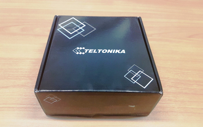
Рисунок 1. Упаковка роутера.
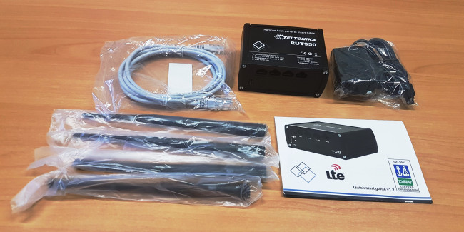
Рисунок 2. Комплектация роутера.
Роутер имеет корпус из металла и пластика в «индустриальном» исполнении. Для доступа к слотам для SIM-карт необходимо снять заднюю крышку устройства. Имеются 2 разъема для полноразмерных SIM-карт.
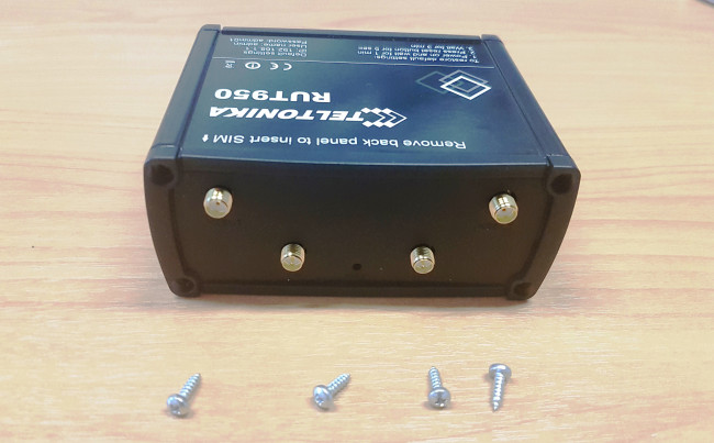
Рисунок 3. Снятие крышки для доступа к SIM карте.
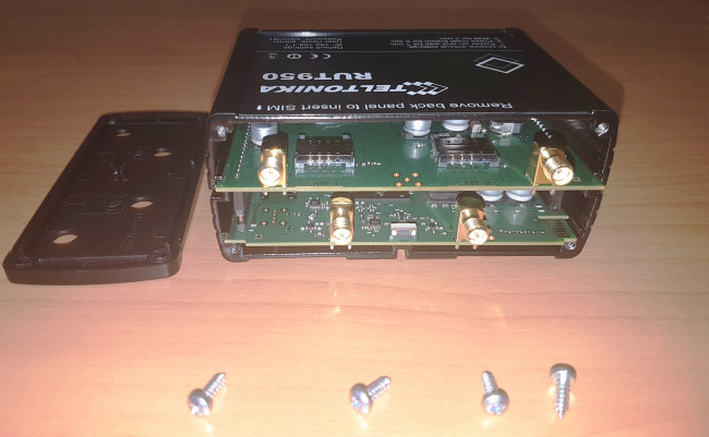
Рисунок 4. Разъемы для SIM карт.
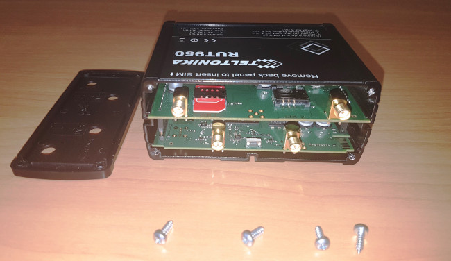
Рисунок 5. Установка SIM карты.
Роутер имеет 2 SMA-разъема для подключения съемных антенн мобильной связи и 2 RP-SMA-разъема для Wi-Fi антенн. Это означает, что при необходимости можно использовать более мощные антенны или использовать направленные антенны для подключения к отдаленным вышкам сотовых операторов (к примеру линейка антенн
Itelite
).
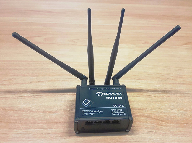
Рисунок 6. Передняя панель роутера, порты.
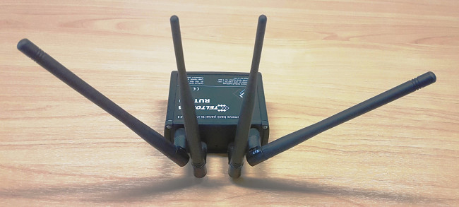
Рисунок 7. Задняя панель роутера, антенны.
2. Базовая настройка маршрутизатора.
Для теста использовалась SIM карта «красного» оператора. При первом подключении к роутеру был запущен мастер настройки (логин/пароль по умолчанию admin/admin01).
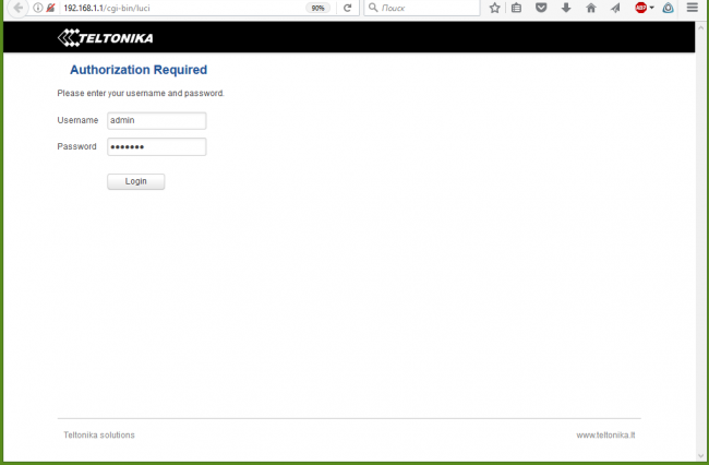
Рисунок 8. Экран входа в систему.
На первом шаге мастер настройки предложил изменить пароль администратора и указать системное время. После этого указываются параметры мобильного подключения. Практически, необходимо только указать имя оператора. На третьем этапе указываются параметры локальной сети и DHCP сервиса. В заключение, настраивается Wi-Fi подключение.
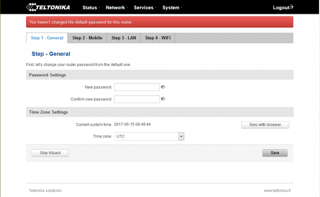
Рисунок 9. Мастер настройки роутера, шаг 1. Пароль и время.
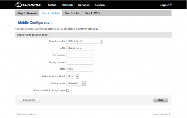
Рисунок 10. Мастер настройки роутера, шаг 2. Мобильная сеть.
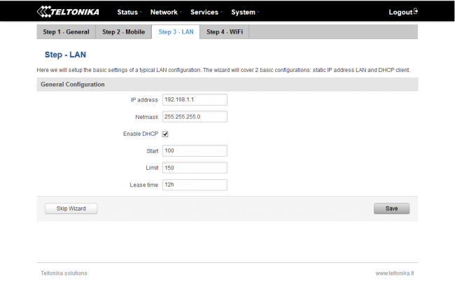
Рисунок 11. Мастер настройки роутера, шаг 3. Локальная сеть.
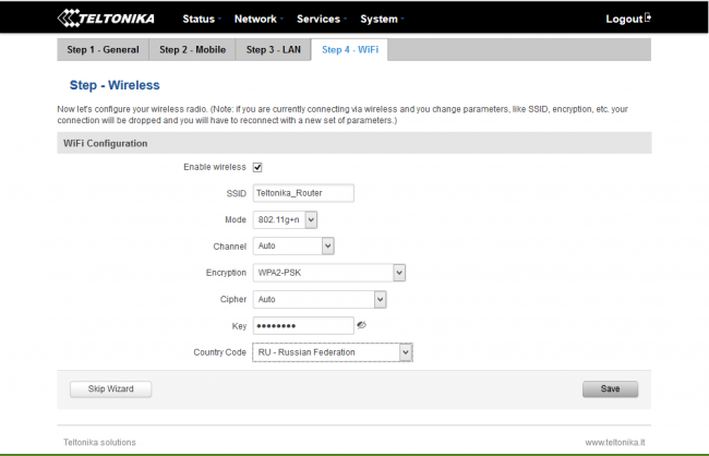
Рисунок 12. Мастер настройки роутера, шаг 4. Беспроводная сеть.
После первичной настройки роутер готов к работе. На информативном экране состояния можно увидеть текущий статус мобильного, проводного и Wi-Fi соединения, системные и сетевые события. Роутер практически мгновенно подключился к сети LTE сотового оператора . Тест скорости показал вполне неплохие результаты.
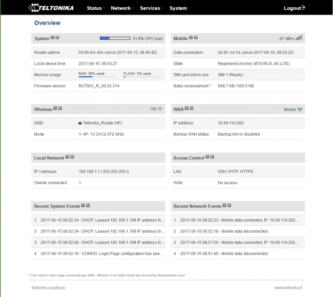
Рисунок 13. Экран состояния системы.
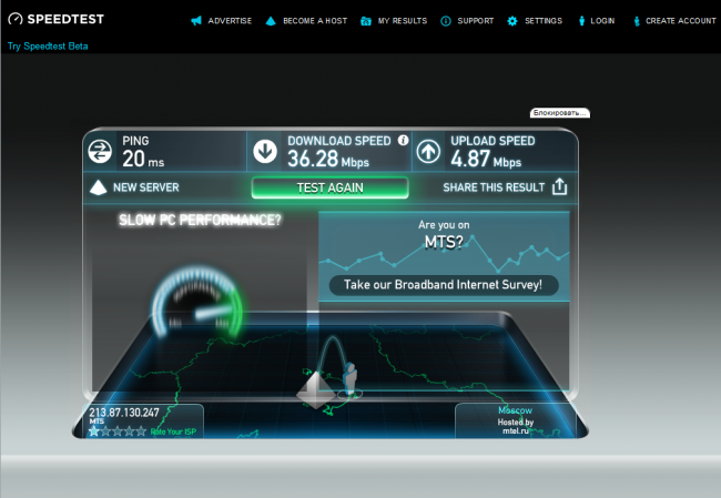
Рисунок 14. Тест скорости мобильной сети.
3. Расширенные настройки маршрутизатора.
Возможности по дополнительной настройке маршрутизатора очень широки, и обзор многих из них потребовал бы объема сравнимого со всей этой статьей. Поэтому, далее будут кратко рассмотрены основные параметры настройки…
Как уже упоминалось, роутер Teltonika RUT 950
позволяет использовать 2 SIM-карты. Базовая настройка позволяет указать режим работы и PIN-код. При необходимости можно запретить передачу данных в роуминге, а также принудительно использовать только LTE-подключение. Настройки переключения SIM-карт позволяют переключаться между операторами в случае потери сигнала, при достижении определённого лимита на передачу данных или SMS сообщений, а также в зависимости от ряда других параметров. Закладка выбора сотового оператора позволяет указать, к какой сети следует подключаться для каждой SIM-карты.
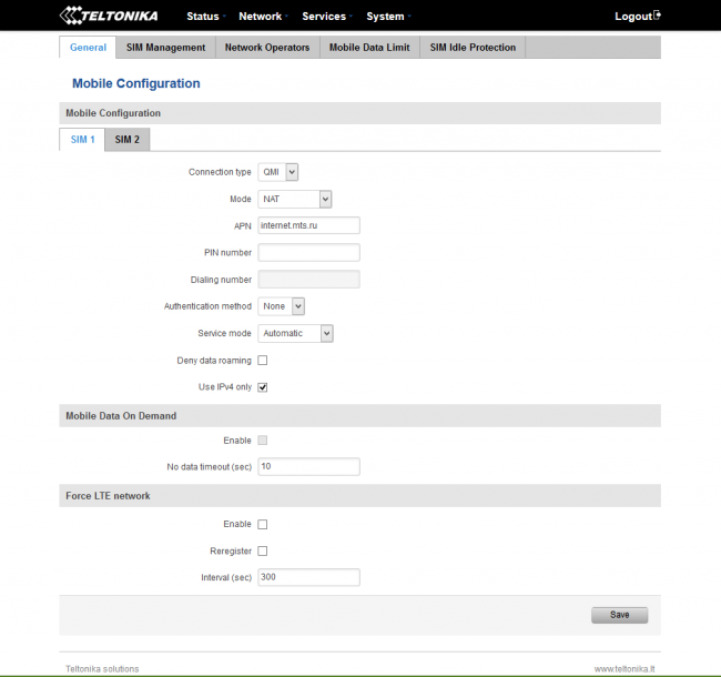
Рисунок 15. Конфигурация мобильных сетей. Общие настройки.
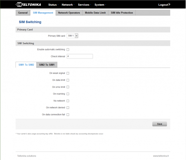
Рисунок 16. Конфигурация мобильных сетей. Настройка переключения SIM -карт.
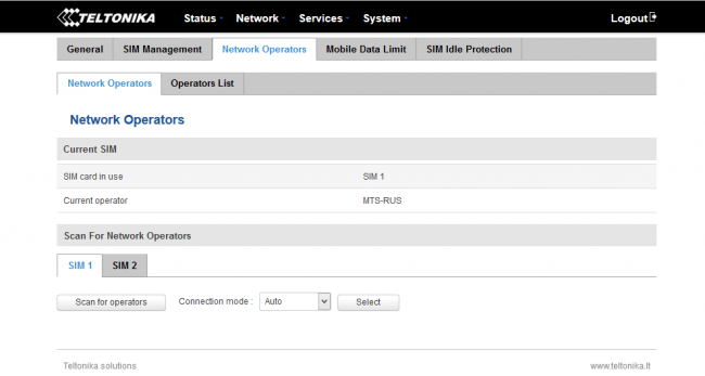
Рисунок 17. Конфигурация мобильных сетей. Операторы.
Поскольку мобильные тарифы, как правило, включают ограниченный пакет трафика, в роутере можно установить лимит на использование данных для каждой SIM-карты! При приближении к лимиту может быть выслано SMS предупреждение.
Настройка «SIM Idle Protection» позволяет защититься от отключения мобильной связи. При активации опции роутер будет периодически посылать PING-запросы на определенный адрес через мобильный интерфейс.
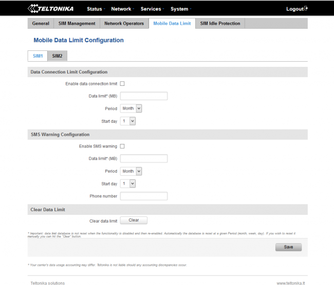
Рисунок 18. Конфигурация мобильных сетей. Лимиты данных.
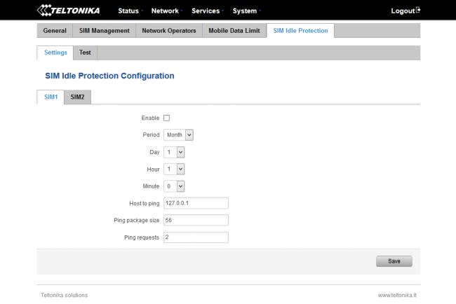
Рисунок 19. Конфигурация мобильных сетей. Защита от отключения SIM карт.
Роутер Teltonika RUT 950
может использоваться не только в качестве исключительно 3G/LTE-устройства. Фактически, поддерживаются 3 способа подключения к сети Интернет: проводное Ethernet, мобильное и Wi-Fi. В последнем случае роутер выступает в качестве клиента провайдерской беспроводной сети. Крайне интересной и полезной особенностью является возможность создания отказоустойчивой конфигурации для подключения к Интернету. После настройки отказоустойчивости и выбора приоритета для каждого подключения роутер будет автоматически переключаться на следующий резервный канал при разрыве связи. Роутер позволяет указать сервера для контроля связи, а также время разрыва, при котором будет происходить переподключение. Тестирование было выполнено при настройке проводной сети в качестве основной и мобильной, как резервной. При отключении кабеля, роутер через 5 секунд подключился через мобильную сеть. При восстановлении проводного соединения роутер также через несколько секунд вернулся к использованию основного подключения WAN. Такая опция делает роутер очень полезным в приложениях, требующих постоянного подключения к сети Интернет.
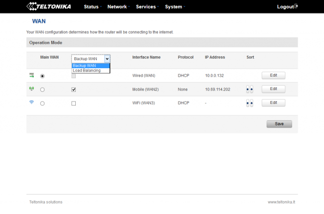
Рисунок 20. Настройка WAN , выбор режима резервирования.
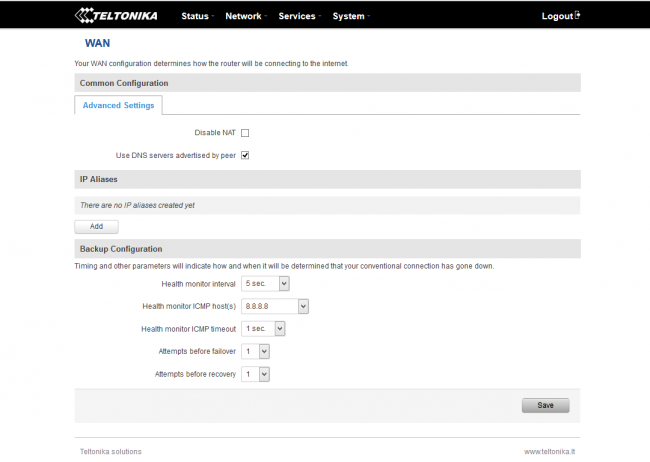
Рисунок 21. Настройка режима резервирования.
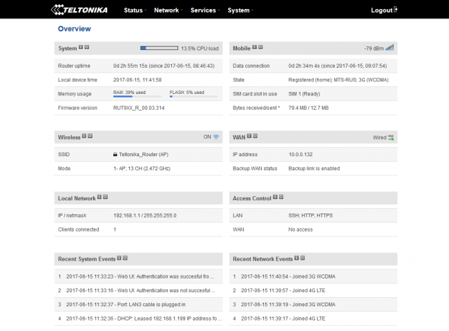
Рисунок 22. Экран статуса системы, активна проводная сеть WAN .
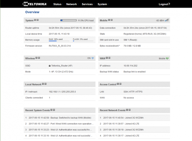
Рисунок 23. Экран статуса системы, переключение на мобильную сеть при отключении проводной сети WAN .
Настройки локальной сети касаются в основном адреса роутера и параметров DHCP-сервера. Они достаточно стандартны и похожи на настройки любого современного офисного маршрутизатора.
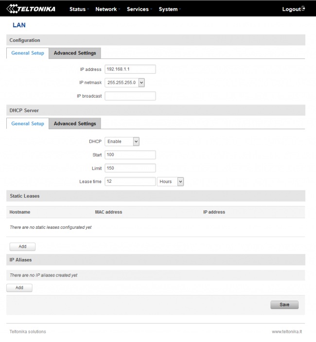
Рисунок 24. Настройки локальной сети.
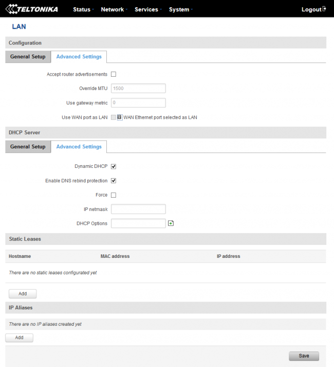
Рисунок 25. Дополнительные настройки локальной сети.
Wi-Fi модуль в составе роутера работает на частоте 2.4 ГГц в MIMO 2×2 режиме. Поддерживается создание нескольких Wi-Fi сетей. Поддерживаются различные режимы шифрования (WEP, WPA, WPA2). При необходимости, можно осуществлять фильтрацию клиентов по MAC-адресам, изолировать клиентов беспроводной сети друг от друга. Роутер также поддерживает создание hotspot’а для авторизации клиентов в гостевой сети.
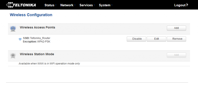
Рисунок 26. Настройки Wi — Fi сети.
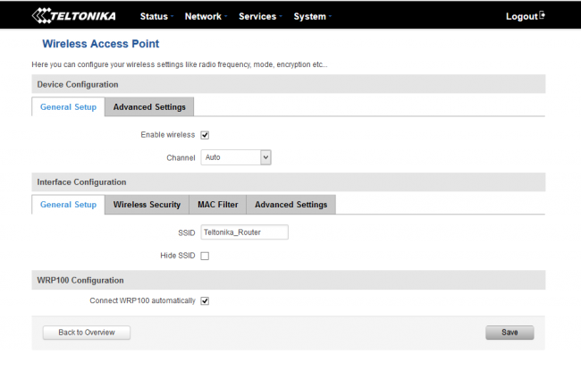
Рисунок 27. Настройки Wi — Fi сети. Общие параметры.
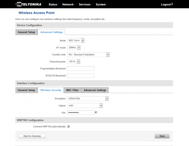
Рисунок 28. Настройки Wi — Fi сети. Параметры радио и безопасности.
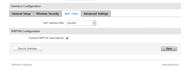
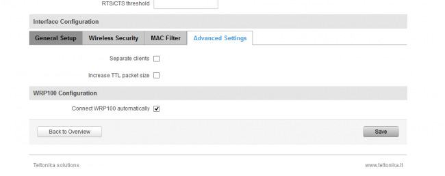
Рисунок 30. Настройки Wi — Fi сети. Дополнительные параметры.
Роутер имеет мощный межсетевой экран, построенный на основе iptables. Его возможности по контролю трафика практически не ограничены и включают различные правила обработки, проброс портов, защиту от DDOS-атак и сканирования портов. Если какие то правила не могут быть созданы в интерфейсе управления, возможно создание собственных правил обработки, основанных на командах iptables. Эти команды будут применены при каждом перезапуске роутера непосредственно после загрузки основного пакета правил.
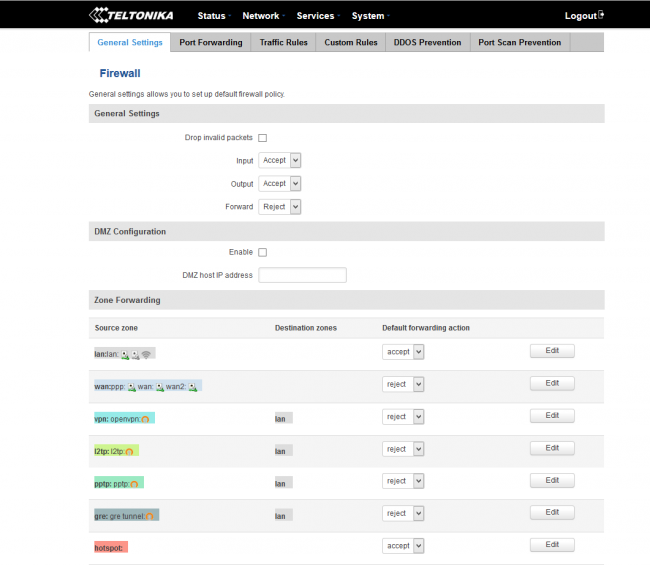
Рисунок 31. Настройка межсетевого экрана.
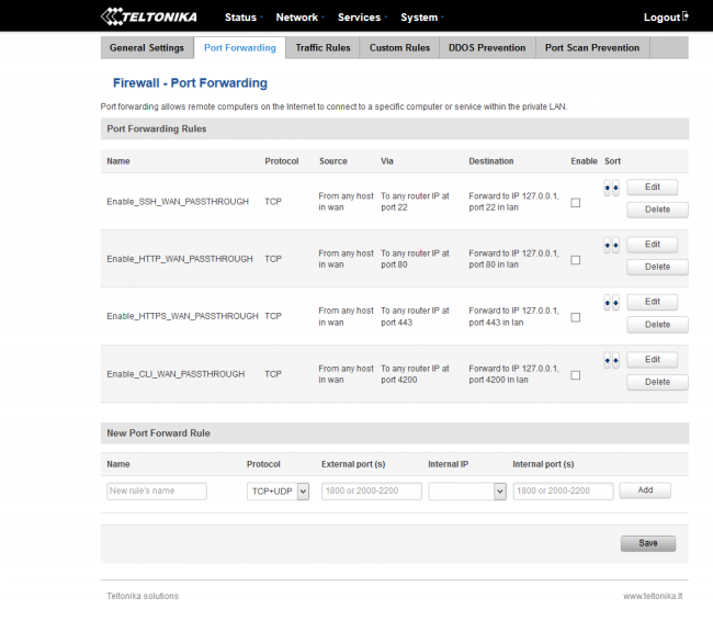
Рисунок 32. Настройка проброса портов.
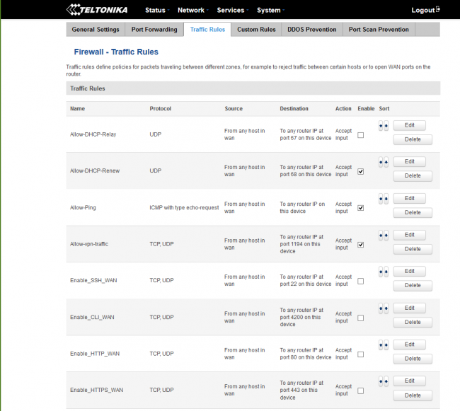
Рисунок 33. Правила обработки трафика.
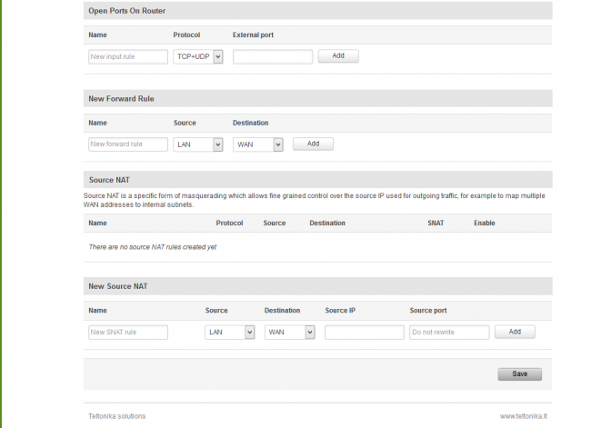
Рисунок 34. Правила обработки трафика, продолжение.
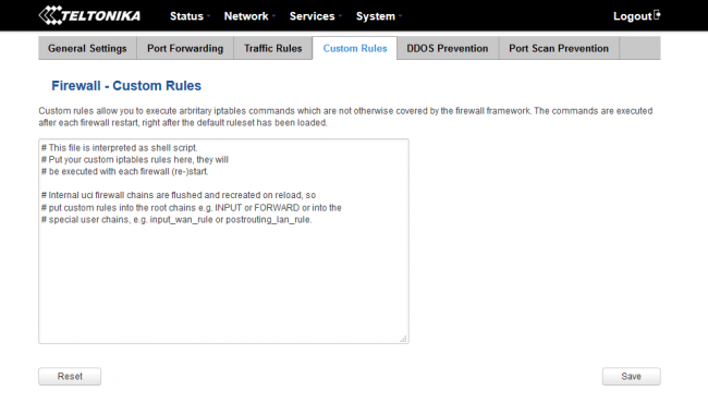
Рисунок 35. Создание собственных правил обработки.
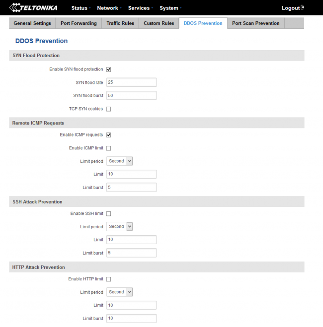
Рисунок 36. Защита от DDOS атак.
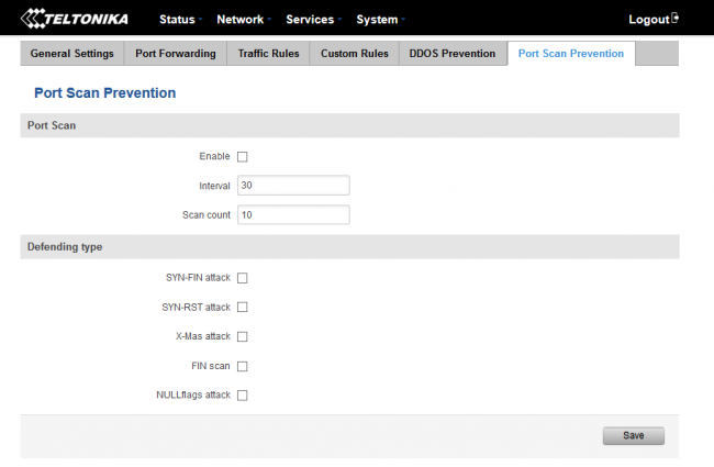
Рисунок 37. Защита от сканирования портов.
Роутер поддерживает статическую и динамическую маршрутизацию, а также протокол OSPF.
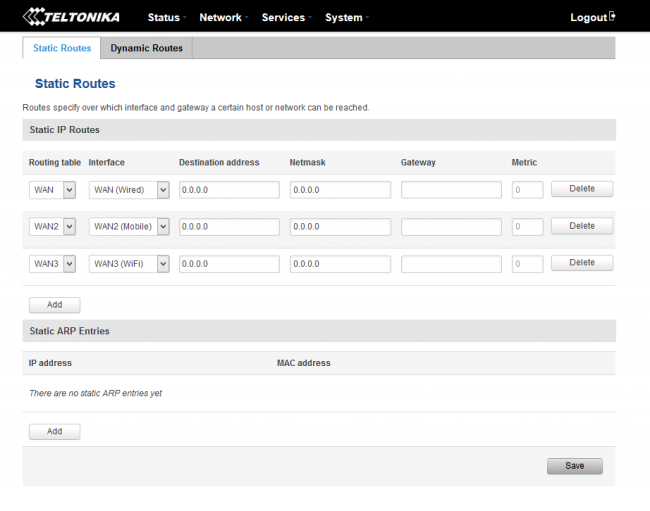
Рисунок 38. Настройка статической маршрутизации.
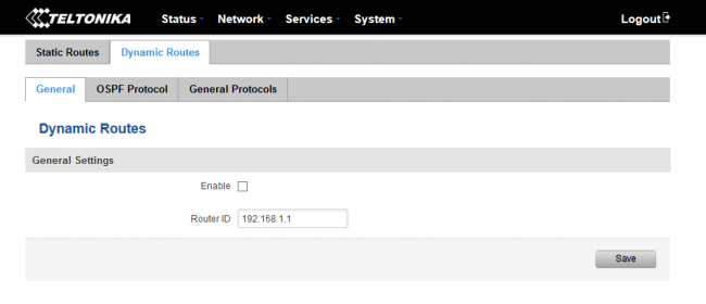
Рисунок 39. Настройка динамической маршрутизации.
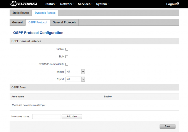
Рисунок 40. Настройка OSPF .
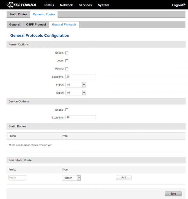
Рисунок 41. Настройка протоколов динамической маршрутизации.
Для подключения к сети WAN можно использовать не только режим отказоустойчивости, но и режим балансировки. В этом режиме трафик будет распределяться между интерфейсами в зависимости от заранее указанного соотношения.
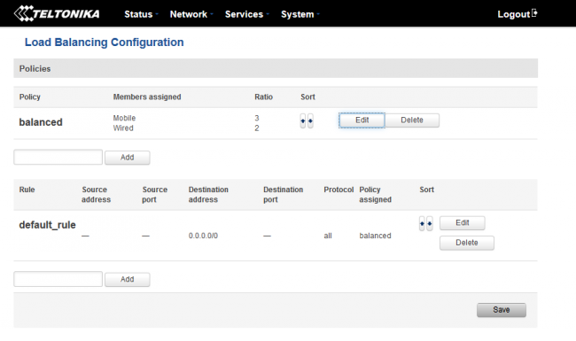
Рисунок 42. Настройка конфигурации балансировки нагрузки WAN .
Роутер позволяет использовать ряд полезных сервисов, включая организацию hotspot, веб-фильтрацию, внешнее управление TR-808 и ряд других. Одной из самых интересных функций является внешнее управление через SMS сообщения.
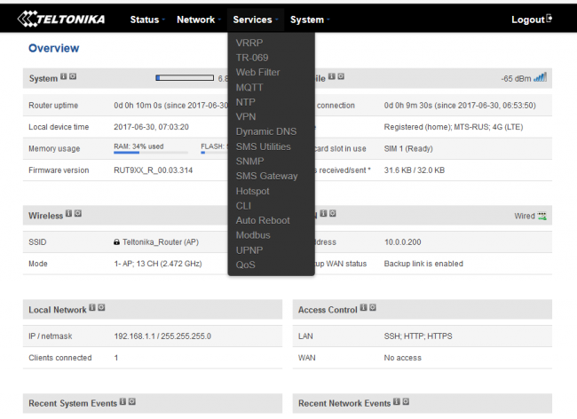
Рисунок 43. Службы маршрутизатора.
4. Возможности удаленного управления маршрутизатором через SMS.
Роутер Teltonika RUT 950
поддерживает удаленное управление через SMS-сообщения. Список команд очень широк и позволяет, например, перезагрузить роутер, сбросить настройки, применить определенную конфигурацию, включить или выключить Wi-Fi, а также многие другие возможности. Помимо этого, некоторые функции также доступны и через звонок!
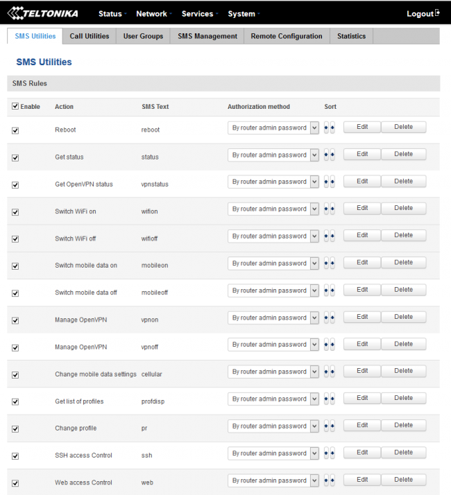
Рисунок 44. SMS утилиты.
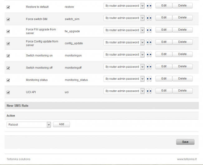
Рисунок 45. SMS -утилиты, продолжение.
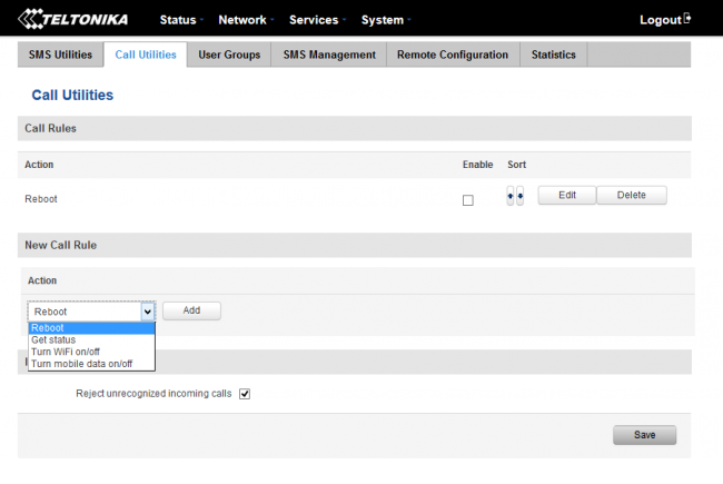
Рисунок 46. CALL -утилиты.
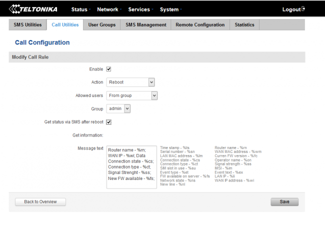
Рисунок 47. Настройка CALL утилиты.
Для обеспечения безопасности SMS и звонков, роутер поддерживает создание групп телефонных номеров, с которых допускается доступ.
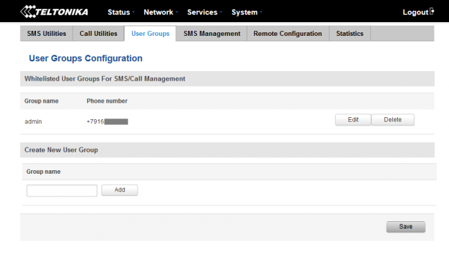
Рисунок 48. Настройка групп отправителей.
В ходе тестирования была проверена возможность SMS-управления. Команды по SMS по умолчанию требуют авторизации в виде пароля администратора роутера. На телефонный номер роутера была отправлена команда на перезагрузку. Формат команды – «пароль reboot». После этого была отправлена команда прислать данные о текущем статусе. Формат команды «пароль status». Обе команды были выполнены без проблем. Также возможно посылать произвольные SMS-сообщения на роутер и с роутера. Результаты действий можно просмотреть в журнале текущих событий.
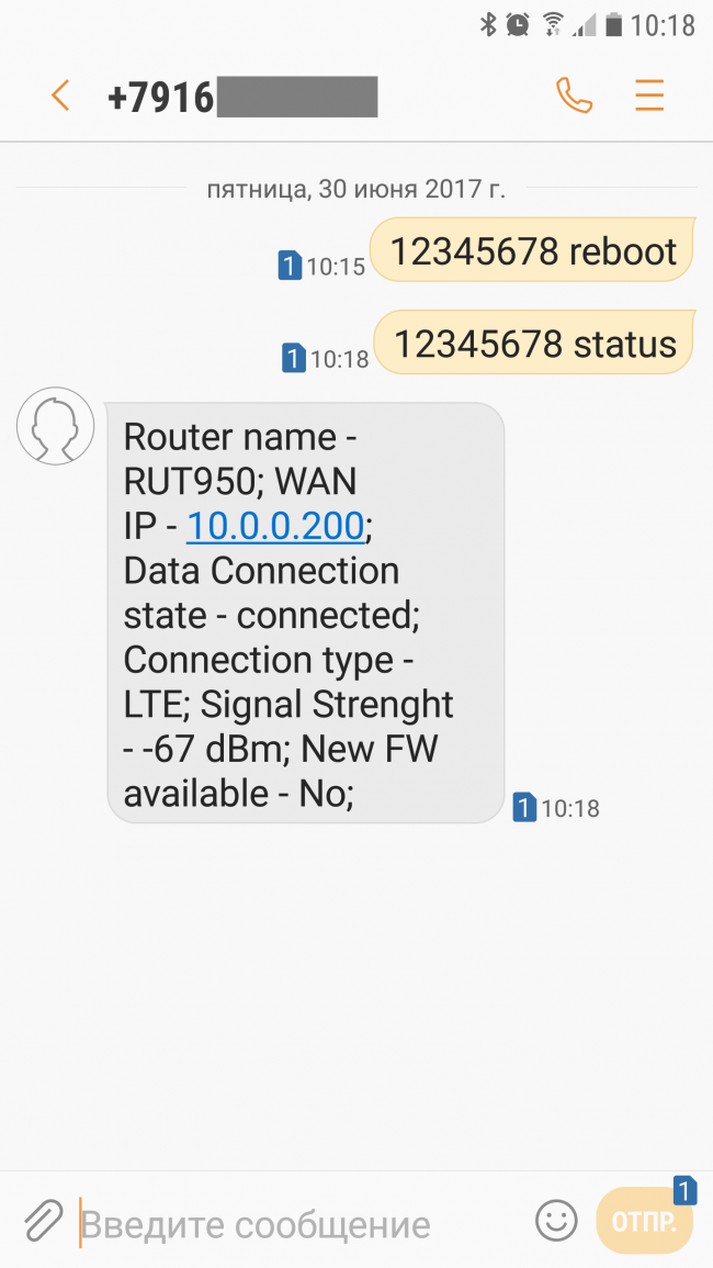
Рисунок 49. Отправка SMS для перезагрузки и получения статуса устройства.
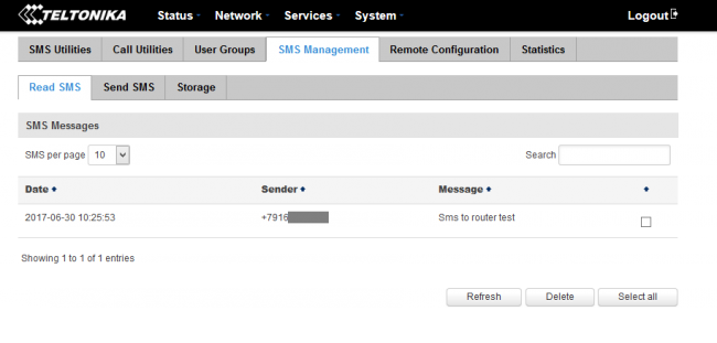
Рисунок 50. Принятые произвольные SMS .
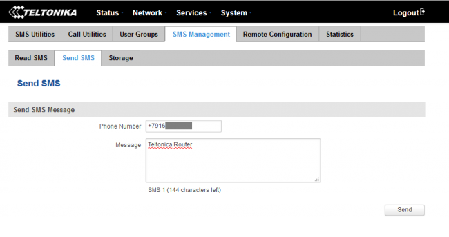
Рисунок 51 . Отправка произвольного SMS .
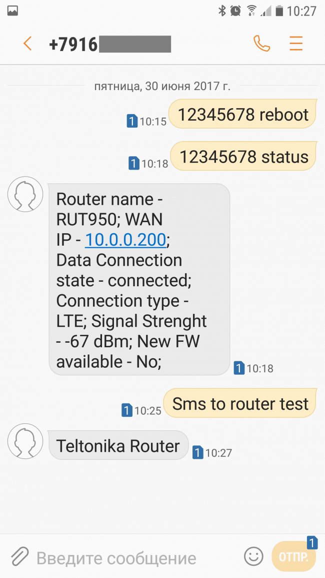
Рисунок 52. Отправки и принятие произвольных SMS на телефоне.
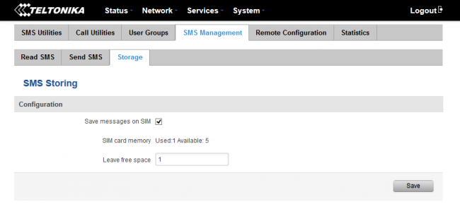
Рисунок 53. Хранение SMS .
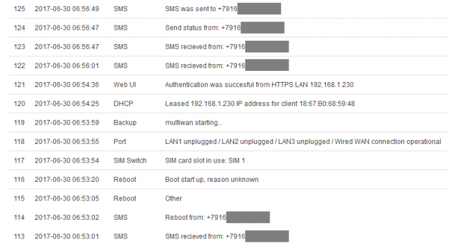
Рисунок 54. Лог событий, включая удаленную перезагрузку роутера по SMS .
5. Настройка основных параметров администрирования.
В завершение, рассмотрим основные параметры администрирования роутера. Из соответствующего меню настройки можно сменить пароль администратора, выполнить резервное копирование и восстановление настроек, включить доступ к интерфейсу или CLI по определенным протоколам, отображение определенной информации на экране входа в систему.
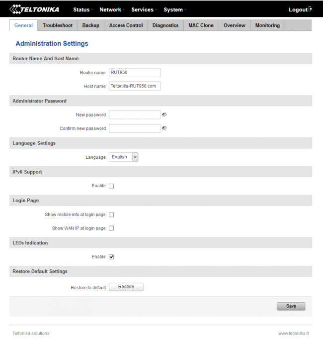
Рисунок 55. Параметры администрирования роутера.
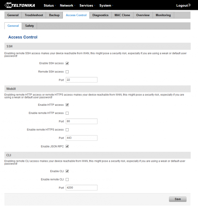
Рисунок 56. Настройка портов для доступа к администрированию.
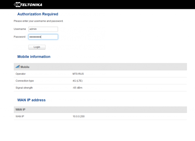
Рисунок 57. Экран входа в систему с дополнительной информацией о сети.
6. Выводы.
3G/LTE-роутер Teltonika RUT 950
представляет собой не просто отличный маршрутизатор для подключения к мобильной сети. Он может быть рекомендован во всех случаях, когда требуется высокая доступность Интернет-подключения. Функции удаленного управления по SMS могут не только облегчить работу администратора, но и стать крайне полезным инструментов безопасности, например, для предотвращения доступа к важной информации в случае необходимости. Все это в сочетании с вполне бюджетной стоимостью делает маршрутизатор Teltonika RUT 950
весьма привлекательным инструментом доступа в сеть Интернет как для организаций, так и для частных клиентов!
Посмотреть инструкция для Teltonika RUT950 бесплатно. Руководство относится к категории маршрутизаторы (роутеры), 11 человек(а) дали ему среднюю оценку 8. Руководство доступно на следующих языках: английский. У вас есть вопрос о Teltonika RUT950 или вам нужна помощь? Задайте свой вопрос здесь
Не можете найти ответ на свой вопрос в руководстве? Вы можете найти ответ на свой вопрос ниже, в разделе часто задаваемых вопросов о Teltonika RUT950.
В чем разница между роутером и модемом?
От чего зависит скорость загрузки в Интернете?
Вредно ли Wi-Fi-излучение?
Какой вес Teltonika RUT950?
Какая высота Teltonika RUT950?
Какая ширина Teltonika RUT950?
Какая толщина Teltonika RUT950?
Инструкция Teltonika RUT950 доступно в русский?
Не нашли свой вопрос? Задайте свой вопрос здесь


