-
Contents
-
Table of Contents
-
Troubleshooting
-
Bookmarks
Quick Links
The Safe Scrubbing Alternative
Hygenic
Fully Cleanable Tanks
TennantTrue
Parts
IRIS
a Tennant Technology
North America / International
For the latest Parts manuals and other
language Operator manuals, visit:
www.tennantco.com/manuals
R
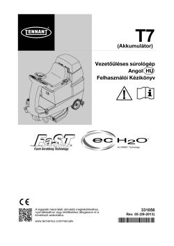
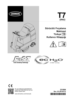
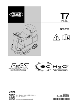
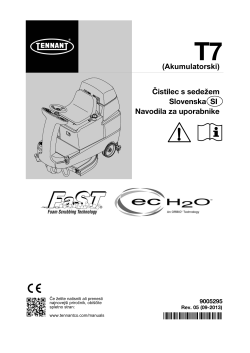
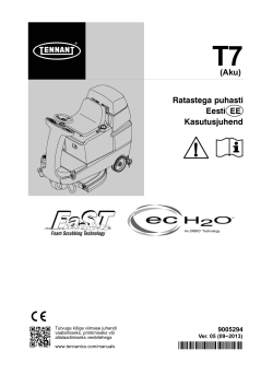
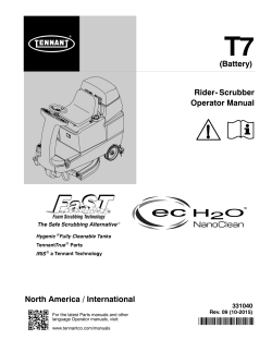
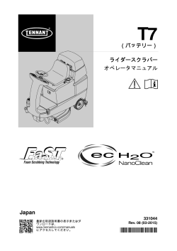
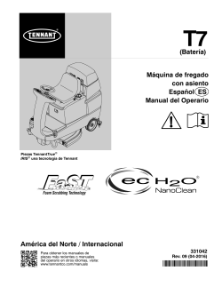
T7
(Battery)
Rider- Scrubber
Operator Manual
331040
Rev. 09 (10-2015)
*331040*
Related Manuals for Tennant T7
Summary of Contents for Tennant T7
-
Page 1
Operator Manual The Safe Scrubbing Alternative Hygenic Fully Cleanable Tanks TennantTrue Parts IRIS a Tennant Technology North America / International 331040 Rev. 09 (10-2015) For the latest Parts manuals and other language Operator manuals, visit: *331040* www.tennantco.com/manuals… -
Page 2
Installation Date — INTENDED USE The T7 is an industrial/commercial rider machine designed to wet scrub both rough and smooth hard surfaces (concrete, tile, stone, synthetic, etc). Typical applications include schools, hospitals / health care facilities, office buildings, and retail centers. Do not use this machine on soil, grass, artificial turf, or carpeted surfaces. This machine is intended for indoor use only. -
Page 3: Table Of Contents
….Checking On- Board Battery Charger Settings ……T7 331040 (10- 2015)
-
Page 4: Safety Precautions
3. When using machine: because of concerns related to equipment — Use only as described in this manual. interference, please contact a Tennant — Use brakes to stop machine. representative for information on how to — Go slowly on inclines and slippery disable the cellular communication surfaces.
-
Page 5
— All repairs must be performed by a trained service mechanic. — Do not modify the machine from its original design. — Use Tennant supplied or approved replacement parts. — Wear personal protective equipment as needed and where recommended in this manual. -
Page 6
Electrical components, use cause explosion or fire. Do not grounding strap before pick up. opening panel. Located on electrical panel under the seat Located under the solution fill port and next to foot pedals T7 331040 (9- 2013) -
Page 7: Operation
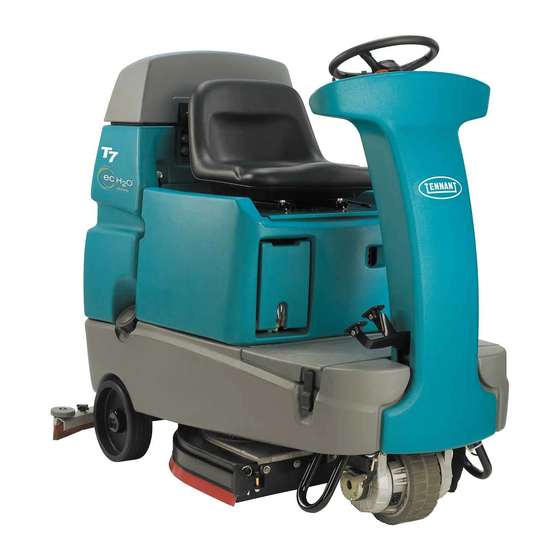
S. Battery charging connector H. Scrub head T. Propel pedal I. Steering wheel U. Brake pedal J. Solution tank K. Tool Box or optional FaST- PAK compartment ec- H2O System Module (option) L. Solution tank fill cap T7 331040 (02- 09)
-
Page 8: Controls And Instruments
K. ec- H2O system indicator light (option) L. Vacuum fan / squeegee button M. Brush Pressure increase button (+) N. Brush Pressure decrease button (- ) O. Solution increase button (+) P. Solution decrease button (- ) Q. Control panel cover T7 331040 (02- 09)
-
Page 9: How The Machine Works
BRUSH INFORMATION section of this tank. Drain, rinse and refill the solution tank with manual or contact a Tennant representative. clear cool water before operating the FaST system. Conventional cleaning detergents may cause failure to the FaST system.
-
Page 10: (Ec-H2O Model)
Polishing pad — This white pad is for polishing floors. Maintains a high gloss. Use for buffing very soft finishes and lower traffic areas, and polishing soft waxes on wood floors. T7 331040 (03- 2015)
-
Page 11: Machine Setup
To install the brushes or pad, see REPLACING The ec-H2O system indicator light will blink DISK SCRUB BRUSHES OR PAD DRIVER or green/red when it’s time to replace cartridge. REPLACING CYLINDRICAL SCRUB BRUSHES section of this manual. T7 331040 (03- 2015)
-
Page 12: Installing The Fast- Pak (Fast Model)
NOTE: The FaST- PAK Floor Cleaning Concentrate is specially designed for use with the FaST system scrubbing application. NEVER use a substitute. Other cleaning solutions may cause FaST system failure. T7 331040 (03- 2015)
-
Page 13: Filling The Solution Tank
Plan the scrubbing in advance. Try to arrange long runs with minimum stopping and starting. Do an entire floor or section at one time. Pre- sweep the area to prevent streaking. T7 331040 (9- 2013)
-
Page 14: Setting Scrub Modes
H2O System Indicator Light ATTENTION: ec-H2O NanoClean Models- During first time use and after replacing the water conditioning cartridge, the ec-H2O system will automatically override the selected solution flow rate for up to 75 minutes. T7 331040 (03- 2015)
-
Page 15: Economy Setting
FaST/ec- H2O solution system. Drain, rinse and refill solution tank with cool clean water before operating the FaST/ec- H2O system. NOTE: For ec-H2O models manufactured before ec-H2O NanoClean models, contact an Authorized Service Center if solution flow rate adjustment is required. T7 331040 (03- 2015)
-
Page 16
The light next to the One Step or fire. Do not pick up. Scrub button will turn off and the scrubbing functions will turn off after a short delay. T7 331040 (9- 2013) -
Page 17: Double Scrubbing
The light above the vacuum fan button will turn off, the squeegee will raise and the vacuum fan will stop operating. Then scrub the area. Let the cleaning solution set on the floor for 3- 5 minutes. T7 331040 (9- 2013)
-
Page 18: Water Pickup Mode (No Scrubbing)
Drive the machine slowly on inclines. Use the brake pedal to control machine speed on descending inclines. Scrub with the machine up inclines rather than down inclines. FOR SAFETY: When using machine, go slowly on inclines and slippery surfaces. T7 331040 (03- 2015)
-
Page 19: Emergency Stop Button
Solid red Contact Service Center If an alarm sounds and the ec- H2O system indicator light begins to blink red, the ec- H2O module must be flushed to resume ec- H2O operation (See ec-H2O MODULE FLUSH PROCEDURE). T7 331040 (03- 2015)
-
Page 20: Solution Tank Empty Indicator
See BATTERIES in the MAINTENANCE section. NOTE: The blinking left battery discharge light will not reset from blinking until the batteries are fully charged. T7 331040 (9- 2013)
-
Page 21: Fault Indicator
Brush Pressure Light overloaded (possibly from string or or Contact Tennant service both blink banding wrapped around motor) representative Fault Light and Vacuum Fan Motor is overloaded Contact Tennant service Vacuum Fan Light representative both blink T7 331040 (02- 09)
-
Page 22: Circuit Breakers
The circuit breakers are located inside the battery hazard light. compartment next to the hour meter. The chart shows the circuit breakers and the electrical components they protect. Circuit Breaker Rating Circuit Protected Instrument Panel — power 15 A Accessories T7 331040 (9- 06)
-
Page 23: Draining And Cleaning The Tanks
7. Replace the recovery tank drain hose cap and mount the drain hose back onto the mounting clip after the tank is drained. T7 331040 (9- 2013)
-
Page 24
11. Tilt the recovery tank back to access the solution tank cover. Wipe the bottom of the solution tank. Make sure the recovery tank is cover and the tank seal before replacing the empty before tilting. cover. T7 331040 (9- 2013) -
Page 25: Propel System Troubleshooting
8 times Horn repeatedly ON/OFF key switch is turned on while Unplug battery charger before starting beeps 9 times battery charger is plugged into machine machine Fault Light blinks Propel motor is overloaded Contact Tennant service representative T7 331040 (9- 2013)
-
Page 26: Machine Troubleshooting
Worn scrub brush Replace scrub brush Broken or loose brush drive belt Replace or tighten belt (Cylindrical models) Brush pressure set too light Increase brush pressure Low battery charge Charge batteries until the charger automatically turns off T7 331040 (02- 09)
-
Page 27
Contact Service Center light solid red ec- H2O system indicator Defective light or module Contact Service Center light does not turn on No water flow Clogged module Contact Service Center Defective solution pump Replace solution pump T7 331040 (03- 2015) -
Page 28: Maintenance
MAINTENANCE MAINTENANCE 355033 T7 331040 (02- 09)
-
Page 29: Maintenance Chart
500 hour check) Tires Check for damage and wear 1000 FaST water and air Replace Hours filters (option) LUBRICANT/FLUID ..Distilled water NOTE: More frequent maintenance intervals may be required in extremely dusty conditions. T7 331040 (9- 2013)
-
Page 30: Batteries
Replace any worn or damaged wires. Do not system. remove battery caps when cleaning batteries. 08247 FOR SAFETY: When servicing machine, keep all metal objects off batteries. Avoid contact with battery acid. T7 331040 (7- 2015)
-
Page 31: Charging The Batteries With Off- Board Charger
OFF- BOARD CHARGER NOTE: If the red “ABNORMAL CYCLE” lamp IMPORTANT: Before charging, make sure that lights when the TENNANT charger is plugged into the battery charger setting is properly set for a wall outlet, the charger cannot charge the the battery type (Refer to charger’s owners…
-
Page 32: Checking On- Board Battery Charger Settings
To select the proper battery type, press the solution flow decrease button (- ) to advance selection. 3. Turn key switch off to save setting. Battery Discharge Indicator LEDs Blinking Green Blinking Red Sealed/AGM/main- Wet/lead acid tenance free battery battery T7 331040 (7- 2015)
-
Page 33: Charging The Batteries With The On- Board Charger
E03 reappears check battery or ies undercharged due to a sulfated replace it. or faulty battery. Safety timer exceeded maximum Replace battery. charging time. Interrupts charging cycle. Possible internal short circuit. Contact Service Center. T7 331040 (9- 06)
-
Page 34: Electric Motors
Proper belt tension is a 6 mm (0.25 in) deflection from a force of 2.3 to 2.5 kg (5.0 to 5.4 lb) at the belt midpoint. Check and adjust the belt tension every 100 hours of operation. T7 331040 (9- 2013)
-
Page 35: Scrub Brushes
Do not wash the pads with a pressure washer. Hang pads, or lie pads flat to dry. NOTE: Always replace brushes and pads in sets. Otherwise one brush or pad will be more aggressive than the other. T7 331040 (10- 2015)
-
Page 36: Replacing Disk Pads
8. Close the side squeegee and the retainer pivot, then insert the pin. 4. Reinsert the pad driver into the machine. NOTE: Be sure the pin is inserted completely through the bottom. T7 331040 (10- 2015)
-
Page 37: Cylindrical Brushes
The idler door of that side of the scrub head is stamped with the same letter. Make sure the letter on the door matches the letter on the scrub head when replacing the doors. T7 331040 (9- 2013)
-
Page 38: Checking Cylindrical Brush Pattern
6. Observe the brush patterns. If the brush pattern is the same width across the entire length of each brush and both brushes are the same width, no adjustment is necessary. 10653 10355 T7 331040 (9- 2013)
-
Page 39: Adjusting Cylindrical Brush Taper
Tighten the mounting screw. 4. Remove idler plate from the scrub head by pressing the spring tab downward. 7. Check the brush patterns again and readjust as necessary until both patterns are the same. T7 331040 (9- 2013)
-
Page 40: Adjusting Cylindrical Brush Width
4. Loosen the jam nut, then adjust the brush width adjustment screw. Tighten the jam nut and the two scrub head mounting screws when finished. 5. Check the brush patterns again and readjust as necessary until both brush patterns are the same. T7 331040 (9- 2013)
-
Page 41: Fast System Maintenance (Fast Model)
2. Remove the injector assembly from the pinch clamps. 3. Replace the water and air filter. An 8mm hex wrench is required to install the new water filter. Air Filter (50 Mesh/Brown) Water Filter (50 Mesh/Brown) T7 331040 (9- 2013)
-
Page 42: Ec- H2O System (Ec- H2O Model)
3 indicator lights Solution flow button 3. Disconnect the two hose connectors from cartridge by pressing the gray collars inward and pulling the connectors outward. Lift 7. Reinstall the battery compartment shroud and cartridge to remove. operator seat. T7 331040 (03- 2015)
-
Page 43: Ec-H2O Module Flush Procedure
4. Turn the key to the on position. 5. Press and release the ec- H2O module flush switch to start the flush cycle. The module is located under the seat T7 331040 (03- 2015)
-
Page 44: Squeegee Blades
8. Install the new front squeegee blade or rotate the existing blade to the new edge. Be sure the holes in the front squeegee blade are 4. Pull the rear squeegee assembly from the hooked onto the tabs on the front blade machine. clamp. T7 331040 (9- 2013)
-
Page 45
11. Reinstall the rear squeegee retaining band onto the squeegee assembly. Be sure each of the flanges on the retaining band are seated in the cut outs in the rear squeegee assembly. 12. Tighten the rear squeegee retaining band tension latch. T7 331040 (9- 2013) -
Page 46: Replacing Side Squeegee Blades
5. Drive the machine forward with the squeegee down to recheck the squeegee blade deflection if adjustments were made. 6. Readjust the squeegee blade deflection if necessary. T7 331040 (9- 2013)
-
Page 47: Adjusting Rear Squeegee Blade Deflection
12 mm (0.50 in) for scrubbing the squeegee blade deflection after smooth floors and 15 mm (0.62 in) for rough adjustments are made. floors. 6. Readjust the squeegee blade deflection if necessary. 12 mm (0.50 in) 03719 T7 331040 (9- 2013)
-
Page 48: Skirts And Seals
The recovery tank seal is located on the bottom of damage and wear after every 500 hours of the recovery tank cover. Check the seal for operation. damage and wear after every 100 hours of operation. T7 331040 (9- 2013)
-
Page 49: Pushing, Towing, And Transporting The Machine
7. Route the rear tie- down straps through the remove the screw driver to enable the parking opening at the center part of the rear axle. brake. FOR SAFETY: Do not operate machine with the brake disabled. T7 331040 (9- 2013)
-
Page 50: Machine Jacking
3. Disconnect batteries before storing. IMPORTANT: Before operating machine, the 4. Park the machine in a cool, dry area. Do not expose the machine to rain. Store indoors. antifreeze must be flushed from the module as described below. T7 331040 (10- 2015)
-
Page 51: Flushing Antifreeze From Ec- H2O Module
Dispose the antifreeze in an environmentally safe way according to local waste disposal regulations. Disconnect the black connector fitting at the scrub head and place the hose into a bucket. 5. The machine is now ready for scrubbing. T7 331040 (3- 2015)
-
Page 52: Specifications
1840 mm (72.5 in) Travel Speed (maximum) 6.4 Km/h (4 mph) Maximum rated climb and descent angle with full tanks 10.5% Maximum rated climb and descent angle with empty tanks 19.25% Maximum rated climb and descent angle when scrubbing T7 331040 (9- 2013)
-
Page 53: Power Type
1.1 L/min (0.30 gpm) Disk model 1.5 L/min (0.40 gpm) Cylindrical brush model 1.9 L/min (0.50 gpm) Optional * ec- H2O models manufactured before ec-H2O NanoClean models — If the optional solution flow rates are required, contact an Authorized Service Center. T7 331040 (03- 2015)
-
Page 54: Machine Dimensions
800 mm (33.25 in) For 800 mm (32 in) squeegee 1000 mm (39.25 in) 1270 mm (50 in) Frame (Disk) 740 mm (29 in) Frame (Cyl) 1520 mm 810 mm (31.7 in) (60 in) 1014751 MACHINE DIMENSIONS T7 331040 (9- 06)
Улучшенная безопасность и санитарные преимущества:
- Поломоечная машина с управлением сидя оставляет свежевымытые полы чистыми, сухими и безопасными для движения благодаря технологиям ec-H2O™.
- Чистите в самых чувствительных к шуму местах благодаря уникально низкому уровню шума, который на 75% ниже, чем у конкурентных моделей.
- Благодаря легко очищаемым и легкодоступным гигиеничным бакам для чистой и грязной воды уменьшается количество налета и бактерий.
Ключевые характеристики производительности и надежности поломоечной машины Tennant T7:
- В машине Tennant Т7 установлены гигиеничные баки, уменьшающие количество плесени, бактерий и других загрязняющих веществ
- Работающая от аккумуляторов поломоечная машина Tennant Т7 практически не издает шума
- Параболическая система скребка обладает оптимальным углом атаки, что позволяет полностью удалять остатки моющего средства
Поломоечная машина Tennant T7 разработана для безопасности:
- Поломоечная машина Tennant Т7 обладает эргономичной конструкцией, позволяющей уменьшить усталость оператора и сделать чистку более комфортной
- Четкий обзор и легкое управление позволяют оператору сосредоточиться исключительно на чистящей поверхности
- Уменьшите риск получения травмы при падении с помощью технологий ec-H2O™, сертифицированных в NSFI (международный институт по безопасности полов)
Выберите лучшую технологию чистки для вашей среды:
- Новая технология ec-H2O™ — электрически активированная вода сокращает негативное влияние на окружающую среду: изготовление упаковки, транспортировку, использование и переработку химикатов
- Используя инновационную систему чистки пеной, поломоечные машины увеличивают производительность до 30%, уменьшают потребление воды до 70% и исключают необходимость контакта оператора с химикатами.
- Extended Scrubbing (ES) — система улучшения производительности. Благодаря лучшему использованию обычного моющего средства, улучшатся результаты чистки, и увеличится производительность.
Tennant T7 – производительная машина с сидячим местом для оператора, для работы которой используются технологии ec-H2O™, снижающие объем моющих средств и расход воды на 80%. Кроме того, улучшены показатели производительности, машина оборудована удобными гигиеническими баками и местом для оператора, эргономичной панелью управления.
Техника может использоваться для жилых помещений, офисов, торговых и развлекательных центров, салонов, гостиниц. Производительность модели равна 2500-3500 кв.м/час, ширина рабочей полосы уборки составляет 80 см.
Особенности модели Теннант Т7
Моющая машина T7 обладает следующими достоинствами:
- производительность – до 2500-5230 кв.м/час;
- ширина дорожки очистки – до 80см;
- наличие мощного мотора со скоростью уборки до 1500 об./мин;
- работа от батреи с емкостью 235 А/ч;
- низкий уровень шума, благодаря показателям с 67 Дба;
- возможность использования модели с технологий ec-H2O.
Модель востребована для уборки офисов, развлекательных центров, гостиниц, жилых помещений, салонов и магазинов. Удобные щетки обеспечивают уборку мусора в труднодоступных места, для работы используется электрический мотор и аккумулятор, что обеспечивать автономность оборудования.
Для заказа модели Теннант Т7 звоните нам по телефону: +7 (812) 425-62-66 или оставляйте онлайн-заявку на сайте с указанием своих контактных данных.
-
manualzz.com
- Industrial & lab equipment
- Scrubber
Инструкции и Руководства для Tennant M-T7.
Мы нашли 64
инструкции доступные для бесплатного скачивания:
Parts Manual, Инструкция по эксплуатации, Руководство пользователя


T7 Parts Manual
Бренд:
Tennant
Категория:
Scrubber
Размер:
5 MB
Страниц:
138
Язык(и):
Словацкий
Оглавление
-
2
HOW TO ORDER PARTS
-
9
GENERAL RECOMMENDED MAINTENANCE
-
9
General Recommended Maintenance Items
-
12
STANDARD PARTS
-
12
Fig. 1 — Replacement Brushes, 650 mm
-
14
Fig. 2 — Replacement Brushes, 800 mm
-
16
Fig. 3 — Main Frame Group, Disk Scrub Head
-
18
Fig. 4 — Main Frame Group, Cylindrical Scrub Head, 700 mm (28 in) (S/N 03941- )
-
20
Fig. 5 — Main Frame Group, Cylindrical Scrub Head, 800 mm (32 in) (S/N 03941- )
-
22
Fig. 6 — Main Frame Group, Cylindrical Scrub Head (S/N 00000- 03940)
-
24
Fig. 7 — Seat Group
-
26
Fig. 8 — Steering Group
-
28
Fig. 9 — Instrument Panel Group
-
30
Fig. 10 — Front Drive Wheel Group (S/N 05316- )
-
32
Fig. 11 — Front Drive Wheel Group (S/N 00000- 05315)
-
34
Fig. 12 — Brake Pedal and Accelerator Pedal Group (S/N 04898- )
-
36
Fig. 13 — Brake Pedal and Accelerator Pedal Group (S/N 04904- 04897)
-
38
Fig. 14 — Brake Pedal and Accelerator Pedal Group (S/N 00001- 04903)
-
40
Fig. 15 — Disk Scrub Head Lift Group
-
42
Fig. 16 — Disk Scrub Head Drive Motor Group, 650 mm
-
44
Fig. 17 — Disk Scrub Head Drive Motor Group, 800 mm
-
46
Fig. 18 — Disk Scrub Head Side Squeegee Group, Right
-
48
Fig. 19 — Disk Scrub Head Side Squeegee Group, Left
-
50
Fig. 20 — Cylindrical Scrub Head Lift Group
-
52
Fig. 21 — Cylindrical Scrub Head Group, 700mm
-
54
Fig. 22 — Cylindrical Scrub Head Group, 800mm
-
56
Fig. 23 — Cylindrical Scrub Head Drive Group, Right Side
-
58
Fig. 24 — Cylindrical Scrub Head Drive Group, Left Side
-
60
Fig. 25 — Cylindrical Scrub Head Squeegee Group
-
62
Fig. 26 — Recovery Tank Group
-
64
Fig. 27 — Vacuum Fan Group
-
66
Fig. 28 — Solution Tank Group, Disk Scrub Head
-
68
Fig. 29 — Solution Tank Group, Cylindrical Scrub Head
-
70
Fig. 30 — Tanks Drain Group
-
72
Fig. 31 — Rear Squeegee Lift Group, Disk Scrub Head
-
74
Fig. 32 — Rear Squeegee Lift Group, Cylindrical Scrub Head
-
76
Fig. 33 — Rear Squeegee Group, 650 mm
-
78
Fig. 34 — Rear Squeegee Group, 800 mm
-
80
Fig. 35 — Circuit Board Group
-
82
Fig. 36 — Electrical Group
-
84
Fig. 37 — Electrical Schematic, Standard & FaST Model (S/N 03500- )
-
86
Fig. 38 — Electrical Schematic, Standard & FaST Model (S/N 00000- 03500)
-
88
Fig. 39 — Electrical Schematic, ec-H2O Model (S/N 03500- )
-
90
Fig. 40 — Wire Harnesses Group, Main (S/N 03500- )
-
93
Fig. 41 — Wire Harnesses Group, Main (S/N 00387- 03499)
-
96
Fig. 42 — Wire Harnesses Group, Main (S/N 00000- 00386)
-
99
Fig. 43 — Wire Harnesses Group, Tank
-
100
Fig. 44 — Wire Harnesses Group, ec-H2O Option (S/N 03500- )
-
101
Fig. 45 — Label Group
-
104
OPTIONS
-
104
Fig. 1 — FaST Group, Disk Scrub Head
-
106
Fig. 2 — FaST Group, Cylindrical Scrub Head
-
108
Fig. 3 — ec-H2O Group, Disc Scrub Head
-
110
Fig. 4 — ec-H2O Group, Cylindrical Scrub Head
-
112
Fig. 5 — Battery Charger Kit, On-Board
-
114
Fig. 6 — Battery and Charger Group 255Ah/5H
-
115
Fig. 7 — Battery and Charger Group 240Ah/5H
-
116
Fig. 8 — Battery and Charger Group 24V/275Ah/5H
-
117
Fig. 9 — Battery and Charger Group 24V/240Ah/5H
-
118
Fig. 10 — Battery and Charger Group 24V/300Ah/5H
-
119
Fig. 11 — Flashing Light Group
-
120
Fig. 12 — Basket Kit
-
121
Fig. 13 — Documentation Group
-
124
BREAKDOWN
-
124
Fig. 1 — Steering Control Breakdown, 1019724
-
125
Fig. 2 — FaST Injector Assembly Breakdown, 9008885
-
126
Fig. 3 — FaST Injector Assembly Breakdown, 9003909
-
127
Fig. 4 — FaST Injector Assembly Breakdown, 9003005
-
128
Fig. 5 — ec-H2O Module Assembly Breakdown, 9007970 (S/N 03938- )
-
130
Fig. 6 — ec-H2O Module Assembly Breakdown, 9006161 (S/N 03500- 03937)
-
132
Fig. 7 — Vacuum Fan Motor Breakdown, 1021064
-
134
Fig. 8 — Front Wheel Gearbox Breakdown, 9008999
-
136
Fig. 9 — Front Wheel Gearbox Breakdown, 9001642, 9009000
Открыть в новой вкладке
Tennant T7 Parts Manual
Бренд:
Tennant
Категория:
Scrubber
Размер:
5 MB
Страниц:
140
Язык(и):
Оглавление
-
2
HOW TO ORDER PARTS
-
3
GENERAL RECOMMENDED MAINTENANCE
-
3
General Recommended Maintenance Items
-
6
STANDARD PARTS
-
6
Fig. 1 — Replacement Brushes, 650 mm (26 in)
-
8
Fig. 2 — Replacement Brushes, 800 mm (32 in)
-
10
Fig. 3 — Main Frame Group, Disk Scrub Head
-
12
Fig. 4 — Main Frame Group, Cylindrical Scrub Head, 700 mm (28 in) (S/N 10448499- )
-
14
Fig. 5 — Main Frame Group, Cylindrical Scrub Head, 800 mm (32 in) (S/N 10448499- )
-
16
Fig. 6 — Main Frame Group, Cylindrical Scrub Head (S/N 00000000- 10448498)
-
18
Fig. 7 — Seat Group
-
22
Fig. 8 — Steering Group
-
24
Fig. 9 — Instrument Panel Group
-
26
Fig. 10 — Front Drive Wheel Group (S/N 10518189- )
-
28
Fig. 11 — Front Drive Wheel Group (S/N 00000000- 10518138)
-
30
Fig. 12 — Brake Pedal and Accelerator Pedal Group (S/N 10644406- )
-
32
Fig. 13 — Brake Pedal and Accelerator Pedal Group (S/N 10508137- 10644405)
-
34
Fig. 14 — Brake Pedal and Accelerator Pedal Group (S/N 00000000- 10508136)
-
36
Fig. 15 — Disk Scrub Head Lift Group
-
38
Fig. 16 — Disk Scrub Head Drive Motor Group, 650 mm (26 in)
-
40
Fig. 17 — Disk Scrub Head Drive Motor Group, 800 mm (32 in)
-
42
Fig. 18 — Disk Scrub Head Side Squeegee Group, Right
-
44
Fig. 19 — Disk Scrub Head Side Squeegee Group, Left
-
46
Fig. 20 — Cylindrical Scrub Head Lift Group
-
48
Fig. 21 — Cylindrical Scrub Head Group, 700mm (28 in)
-
50
Fig. 22 — Cylindrical Scrub Head Group, 800mm (32 in)
-
52
Fig. 23 — Cylindrical Scrub Head Drive Group, Right Side
-
54
Fig. 24 — Cylindrical Scrub Head Drive Group, Left Side
-
56
Fig. 25 — Cylindrical Scrub Head Squeegee Group
-
58
Fig. 26 — Recovery Tank Group
-
60
Fig. 27 — Vacuum Fan Group
-
62
Fig. 28 — Solution Tank Group, Disk Scrub Head
-
64
Fig. 29 — Solution Tank Group, Cylindrical Scrub Head
-
66
Fig. 30 — Tanks Drain Group
-
68
Fig. 31 — Battery Group, 235Ah (S/N 10523206- )
-
70
Fig. 32 — Battery Group, 235Ah (S/N 00000000- 10523205)
-
72
Fig. 33 — Rear Squeegee Lift Group, Disk Scrub Head
-
74
Fig. 34 — Rear Squeegee Lift Group, Cylindrical Scrub Head
-
76
Fig. 35 — Rear Squeegee Group, 650 mm (26 in)
-
78
Fig. 36 — Rear Squeegee Group, 800 mm (32 in)
-
80
Fig. 37 — Circuit Board Group
-
82
Fig. 38 — Electrical Group
-
84
Fig. 39 — Electrical Schematic, Standard & FaST Model (S/N 10426043- )
-
86
Fig. 40 — Electrical Schematic, Standard & FaST Model (S/N 00000000- 10426042)
-
88
Fig. 41 — Electrical Schematic, ec-H2O Model (S/N 10419534- )
-
90
Fig. 42 — Wire Harnesses Group, Main (S/N 10426043- )
-
93
Fig. 43 — Wire Harnesses Group, Main (S/N 10236152- 10426042)
-
96
Fig. 44 — Wire Harnesses Group, Main (S/N 00000000- 10236151)
-
99
Fig. 45 — Wire Harnesses Group, Tank
-
100
Fig. 46 — Wire Harnesses Group, ec-H2O Option (S/N 10419534- )
-
101
Fig. 47 — Label Group
-
104
OPTIONS
-
104
Fig. 1 — FaST Group, Disk Scrub Head
-
106
Fig. 2 — FaST Group, Cylindrical Scrub Head
-
108
Fig. 3 — ec-H2O Group, Disc Scrub Head
-
110
Fig. 4 — ec-H2O Group, Cylindrical Scrub Head
-
112
Fig. 5 — Flashing Light Kit
-
113
Fig. 6 — Battery Group, 180Ah, Maintenance Free
-
114
Fig. 7 — Battery Group, 220Ah, Maintenance Free
-
115
Fig. 8 — Battery Group, 360Ah
-
116
Fig. 9 — Battery Charger Kit, On-Board
-
118
Fig. 10 — Battery Chargers Group, Off-Board
-
120
Fig. 11 — HydroLink Battery Watering System Kit
-
121
Fig. 12 — Basket Kit
-
122
Fig. 13 — Documentation Group
-
124
BREAKDOWNS
-
124
Fig. 1 — Steering Control Breakdown, 1019724
-
125
Fig. 2 — FaST Injector Assembly Breakdown, 9008885
-
126
Fig. 3 — FaST Injector Assembly Breakdown, 9003909
-
127
Fig. 4 — FaST Injector Assembly Breakdown, 9003005
-
128
Fig. 5 — ec-H2O Module Assembly Breakdown, 9007970 (S/N 10449322- )
-
130
Fig. 6 — ec-H2O Module Assembly Breakdown, 9006161 (S/N 10419534- 10449321)
-
132
Fig. 7 — Vacuum Fan Motor Breakdown, 1039763
-
134
Fig. 8 — Vacuum Fan Motor Breakdown, 1021064
-
136
Fig. 9 — Front Wheel Gearbox Breakdown, 9008999
-
138
Fig. 10 — Front Wheel Gearbox Breakdown, 9001642, 9009000
Открыть в новой вкладке
T7+ Parts Manual (S/N 10000- )
Бренд:
Tennant
Категория:
Scrubber
Размер:
6 MB
Страниц:
143
Язык(и):
Словацкий
Оглавление
-
2
HOW TO ORDER PARTS
-
9
GENERAL RECOMMENDED MAINTENANCE
-
9
General Recommended Maintenance Items
-
12
STANDARD PARTS
-
12
Fig. 1 — Replacement Brushes, Cylindrical
-
14
Fig. 2 — Replacement Brushes And Pad Drivers, 650 mm
-
16
Fig. 3 — Replacement Brushes And Pad Drivers, 800 mm
-
18
Fig. 4 — Main Frame Group, Disk Scrub Head
-
20
Fig. 5 — Main Frame Group, Cylindrical Scrub Head, 700 mm
-
22
Fig. 6 — Main Frame Group, Cylindrical Scrub Head, 800 mm
-
24
Fig. 7 — Seat Group
-
26
Fig. 8 — Steering Group
-
28
Fig. 9 — Instrument Panel Group
-
30
Fig. 10 — Front Drive Wheel Group
-
32
Fig. 11 — Brake Pedal and Accelerator Pedal Group
-
34
Fig. 12 — Disk Scrub Head Lift Group
-
36
Fig. 13 — Disk Scrub Head Drive Motor Group, 650 mm
-
38
Fig. 14 — Disk Scrub Head Drive Motor Group, 800 mm
-
40
Fig. 15 — Disk Scrub Head Side Squeegee Group, Right
-
42
Fig. 16 — Disk Scrub Head Side Squeegee Group, Left
-
44
Fig. 17 — Cylindrical Scrub Head Lift Group
-
46
Fig. 18 — Cylindrical Scrub Head Group, 700 mm
-
48
Fig. 19 — Cylindrical Scrub Head Group, 800 mm
-
50
Fig. 20 — Cylindrical Scrub Head Drive Group, Right Side
-
52
Fig. 21 — Cylindrical Scrub Head Drive Group, Left Side
-
54
Fig. 22 — Cylindrical Scrub Head Squeegee Group
-
56
Fig. 23 — Recovery Tank Group
-
58
Fig. 24 — Vacuum Fan Group
-
60
Fig. 25 — Solution Tank Group, Disk Scrub Head
-
62
Fig. 26 — Solution Tank Group, Cylindrical Scrub Head
-
64
Fig. 27 — Tanks Drain Group
-
66
Fig. 28 — Rear Squeegee Lift Group, Disk Scrub Head
-
68
Fig. 29 — Rear Squeegee Lift Group, Cylindrical Scrub Head
-
70
Fig. 30 — Rear Squeegee Group, 650 mm
-
72
Fig. 31 — Rear Squeegee Group, 800 mm
-
74
Fig. 32 — Circuit Board Group
-
76
Fig. 33 — Electrical Group
-
78
Fig. 34 — Electrical Schematic, Standard, FaST & ec-H2O Models (S/N 12695- )
-
82
Fig. 35 — Electrical Schematic, Standard, FaST & ec-H2O Models (S/N 11000- 12694)
-
86
Fig. 36 — Electrical Schematic, Standard & FaST Model (S/N 10000- 10999)
-
88
Fig. 37 — Electrical Schematic, ec-H2O Model (S/N 10000- 10999)
-
90
Fig. 38 — Wire Harnesses Group, Main
-
93
Fig. 39 — Wire Harnesses Group, Tank
-
94
Fig. 40 — Wire Harnesses Group, ec-H2O NanoClean (S/N 11000- )
-
95
Fig. 41 — Wire Harnesses Group, ec-H2O (S/N 10000- 11000)
-
96
Fig. 42 — Wire Harnesses Group, ec-H2O NanoClean Main Control Board (S/N 11000- )
-
97
Fig. 43 — Wire Harnesses Group, ec-H2O Main Control Board (S/N 10000- 10999)
-
98
Fig. 44 — Wire Harnesses Group, Iris Telemetry
-
100
Fig. 45 — Cable Assembly, Iris Telemetry
-
101
Fig. 46 — Label Group
-
104
OPTIONS
-
104
Fig. 1 — FaST Group, Disk Scrub Head
-
106
Fig. 2 — FaST Group, Cylindrical Scrub Head
-
108
Fig. 3 — ec-H2O NanoClean Group, Disc Scrub Head (S/N 11000- )
-
110
Fig. 4 — ec-H2O Group, Disc Scrub Head (S/N 10000- 10999)
-
112
Fig. 5 — ec-H2O NanoClean Group, Cylindrical Scrub Head (S/N 11000- )
-
114
Fig. 6 — ec-H2O Group, Cylindrical Scrub Head (S/N 10000- 10999)
-
116
Fig. 7 — Iris Telemetry Group (S/N 11000 — )
-
118
Fig. 8 — Kit, Iris Telemetry Battery Manager
-
120
Fig. 9 — Battery Charger, On-Board (S/N 11773- )
-
122
Fig. 10 — Battery Charger, On-Board (S/N 10000 — 11772)
-
124
Fig. 11 — Battery Group, 360Ah/5H
-
125
Fig. 12 — Battery and Charger Group 255Ah/5H
-
126
Fig. 13 — Battery and Charger Group 240Ah/5H
-
127
Fig. 14 — Battery and Charger Group 180Ah/5H
-
128
Fig. 15 — Battery and Charger Group 24V/275Ah/5H
-
129
Fig. 16 — Battery and Charger Group 24V/240Ah/5H
-
130
Fig. 17 — Battery and Charger Group 24V/300Ah/5H
-
131
Fig. 18 — Flashing Light Group
-
132
Fig. 19 — Documentation Group
-
134
BREAKDOWN
-
134
Fig. 1 — Steering Control Breakdown, 1019724
-
135
Fig. 2 — FaST Injector Assembly Breakdown, 9008885
-
136
Fig. 3 — ec-H2O NanoClean Module Breakdown, 9011810 (S/N 11000- )
-
138
Fig. 4 — ec-H2O Module Assembly Breakdown, 9007970 (S/N 10000- 10999)
-
140
Fig. 5 — Vacuum Fan Motor Breakdown, 1021064
-
142
Fig. 6 — Front Wheel Gearbox Breakdown, 9008999
Открыть в новой вкладке
- Турбины
- Поломоечные машины
- Columbus
- Comac
- Bennett
- Lavor
- STAR (Турция)
- Ghibli
- Portotecnica
- Karcher
- VinnerMyer
- i-mop
- Artred
- Farily
- Gadlee
- KEDI
- TOR
- TVX
- Метлана
- Мобайл Клининг
- Fimap
- Tennant
- Viper
- Gansow
- Cleanfix
- Factory Cat
- Fiorentini
- Numatic
- Eureka
- Turbolava
- Truvox
- AFC-Group
- Пылесосы
- Бытовая техника Karcher
- Электродвигатели
- Мойки высокого давления
- Минимойки Karcher
- Роторные машины
- Подметальные машины
- Аккумуляторы и з/у
- Чистящие средства
- Уборочный инвентарь
- Запчасти и аксессуары
- Снегоуборочные машины
- Ремонт оборудования
-

Нажимная планка, губа для отжима Euromop
150 руб. (с НДС)
-
Запасная ручка для отжима Euromop
250 руб. (с НДС)
-
Удлинительный шланг высокого давления (10м)
7 650 руб. (с НДС)
-
Комплект зубчатых шестеренок для отжима Euromop
500 руб. (с НДС)
-
Вал для вертикального отжима Eromop
300 руб. (с НДС)

07.08.2021 02:59:27
Представляем новую линейку бюджетных поломоечных машин под маркой TOR (Китай). В ассортименте все размеры скрубберов, от маленькой модели JH350 …
27.10.2020 12:09:04
Остался месяц до 22-й Международной выставки оборудования и средств для профессиональной уборки, санитарии, гигиены, химической чистки и …
30.09.2020 16:35:55
Уважаемые пользователи продукции Karcher!
Доводим до вашего сведения, что все версии однодисковых машин Karcher BDS С Adv – будут …
12.12.2019 09:58:36
С удовольствием представляем линейку поломоечных машин Viper. Этот китайский производитель является подразделением мирового лидера Nilfisk и …
03.04.2019 20:58:26
С 1.04.2019 Kranzle предоставляет 3 года гарантии на АВД, приобретенные у официальных дилеров. Подробности ниже: KRÄNZLE (Германия) …
|
|
||||||||||||||||||||||||||||||||||||||||||||||||||
|
Дополнительные материалы (инструкция, каталог, деталировка, сертификат): |
||||||||||||||||||||||||||||||||||||||||||||||||||
|
Поломоечная машина Tennant T7 — это верх производительности и комфорта. Данная модель оборудована сидением для оператора, что делает процесс работы на данном аппарате легким и даже интересным. Вес поломоечной машины Теннатнт Т7 составляет 386 кг (с батареями), но несмотря на это, уровень шума, который издает аппарат — всего 67 дБа. Это просто невероятный показатель, который на 75% ниже, чем у аналогичных моделей конкурентов. За счет этого вы можете спокойно убирать в среде, чувствительной к шуму. Залы торгового центра или больницы, фойе гостиницы или офис — везде постоянно есть люди, но с этой поломоечной машиной вы им совсем не помешаете. Несмотря на свои размеры, этот аппарат довольно маневренный. Оснащенный баком для воды объемом 110 литров, он способен убирать больше 2 000 квадратных метров в час, требуя при этом минимум человеческих усилий. От оператора требуется лишь сидеть в удобном водительском кресле и рулить, все остальное техника сделает самостоятельно. Выбрав модель Т7 с технологией ec-H2O, вы сможете экономить до 70% воды при уборке, а технология FaST позволит тратить на 90% меньше моющих средств. Гигиенические баки с легким доступом позволят сократить количество бактерий и грязи, которые могут появиться в закрытых баках. Итак, почему же при выборе поломоечной машины стоит обратить внимание именно на модель Tennant T7? 1. Щетки и сквиджеры меняются безо всяких инструментов, легко и просто. 2. Несмотря на наличие сидения для оператора, модель все-таки довольно компактна. 3. Управлять аппаратом сможет даже новичок после минимальной подготовки, что существенно экономит время на подготовку персонала. 4. Параболический сквиджер и система равномерного распределения давления на пол позволяет не оставлять даже малейших следов от моющего средства. 5. Имеется большой выбор щеток и аксессуаров как для уборки строительного мусора, так и для простого мытья ровных полов. В заключении можно добавить, что тот объем работы, который под силу одной поломоечной машине Т7, не сможет выполнить ни один человек. Эффективность, простота и комфорт — вот то, что делает этот аппарат незаменимым в уборке. Наш сайт готов предложить вам широкий ассортимент комплектующих и запчастей для поломоечной машины Теннант Т7 по самым выгодным ценам. Если у вас есть вопросы — задавайте их, наши специалисты дадут вам исчерпывающие ответы. Доставка: Мы доставляем товар по Москве в пределах МКАД, в том числе до транспортных компаний, БЕСПЛАТНО при сумме заказа от 15000 руб. Оплата: Работаем с юридическими лицами по безналичному расчету. Учитываем НДС. Частные лица могут оплатить покупки наличными в офисе или курьеру при доставке. Гарантия: распространяется на всю технику и оборудование. Внимание: условия акций и подарки действительны при цене, указанной на сайте. При предоставлении скидок, акции и подарки могут быть отменены. Подробнее у консультантов. |
||||||||||||||||||||||||||||||||||||||||||||||||||
Есть вопросы?Вы можете задать нам вопрос(ы) с помощью следующей формы. Имя: Пожалуйста, сформулируйте Ваши вопросы относительно Аккумуляторная поломоечная машина Tennant T7 80C (с управлением сидя): |


- Page 1
Operator Manual The Safe Scrubbing Alternative Hygenic Fully Cleanable Tanks TennantTrue Parts IRIS a Tennant Technology North America / International 331040 Rev. 09 (10-2015) For the latest Parts manuals and other language Operator manuals, visit: *331040* www.tennantco.com/manuals… - Page 2
Installation Date — INTENDED USE The T7 is an industrial/commercial rider machine designed to wet scrub both rough and smooth hard surfaces (concrete, tile, stone, synthetic, etc). Typical applications include schools, hospitals / health care facilities, office buildings, and retail centers. Do not use this machine on soil, grass, artificial turf, or carpeted surfaces. This machine is intended for indoor use only. -
Page 3: Table Of Contents
….Checking On- Board Battery Charger Settings ……T7 331040 (10- 2015)
-
Page 4: Safety Precautions
3. When using machine: because of concerns related to equipment — Use only as described in this manual. interference, please contact a Tennant — Use brakes to stop machine. representative for information on how to — Go slowly on inclines and slippery disable the cellular communication surfaces.
- Page 5
— All repairs must be performed by a trained service mechanic. — Do not modify the machine from its original design. — Use Tennant supplied or approved replacement parts. — Wear personal protective equipment as needed and where recommended in this manual. - Page 6
Electrical components, use cause explosion or fire. Do not grounding strap before pick up. opening panel. Located on electrical panel under the seat Located under the solution fill port and next to foot pedals T7 331040 (9- 2013) -
Page 7: Operation
S. Battery charging connector H. Scrub head T. Propel pedal I. Steering wheel U. Brake pedal J. Solution tank K. Tool Box or optional FaST- PAK compartment ec- H2O System Module (option) L. Solution tank fill cap T7 331040 (02- 09)
-
Page 8: Controls And Instruments
K. ec- H2O system indicator light (option) L. Vacuum fan / squeegee button M. Brush Pressure increase button (+) N. Brush Pressure decrease button (- ) O. Solution increase button (+) P. Solution decrease button (- ) Q. Control panel cover T7 331040 (02- 09)
-
Page 9: How The Machine Works
BRUSH INFORMATION section of this tank. Drain, rinse and refill the solution tank with manual or contact a Tennant representative. clear cool water before operating the FaST system. Conventional cleaning detergents may cause failure to the FaST system.
-
Page 10: (Ec-H2O Model)
Polishing pad — This white pad is for polishing floors. Maintains a high gloss. Use for buffing very soft finishes and lower traffic areas, and polishing soft waxes on wood floors. T7 331040 (03- 2015)
-
Page 11: Machine Setup
To install the brushes or pad, see REPLACING The ec-H2O system indicator light will blink DISK SCRUB BRUSHES OR PAD DRIVER or green/red when it’s time to replace cartridge. REPLACING CYLINDRICAL SCRUB BRUSHES section of this manual. T7 331040 (03- 2015)
-
Page 12: Installing The Fast- Pak (Fast Model)
NOTE: The FaST- PAK Floor Cleaning Concentrate is specially designed for use with the FaST system scrubbing application. NEVER use a substitute. Other cleaning solutions may cause FaST system failure. T7 331040 (03- 2015)
-
Page 13: Filling The Solution Tank
Plan the scrubbing in advance. Try to arrange long runs with minimum stopping and starting. Do an entire floor or section at one time. Pre- sweep the area to prevent streaking. T7 331040 (9- 2013)
-
Page 14: Setting Scrub Modes
H2O System Indicator Light ATTENTION: ec-H2O NanoClean Models- During first time use and after replacing the water conditioning cartridge, the ec-H2O system will automatically override the selected solution flow rate for up to 75 minutes. T7 331040 (03- 2015)
-
Page 15: Economy Setting
FaST/ec- H2O solution system. Drain, rinse and refill solution tank with cool clean water before operating the FaST/ec- H2O system. NOTE: For ec-H2O models manufactured before ec-H2O NanoClean models, contact an Authorized Service Center if solution flow rate adjustment is required. T7 331040 (03- 2015)
- Page 16
The light next to the One Step or fire. Do not pick up. Scrub button will turn off and the scrubbing functions will turn off after a short delay. T7 331040 (9- 2013) -
Page 17: Double Scrubbing
The light above the vacuum fan button will turn off, the squeegee will raise and the vacuum fan will stop operating. Then scrub the area. Let the cleaning solution set on the floor for 3- 5 minutes. T7 331040 (9- 2013)
-
Page 18: Water Pickup Mode (No Scrubbing)
Drive the machine slowly on inclines. Use the brake pedal to control machine speed on descending inclines. Scrub with the machine up inclines rather than down inclines. FOR SAFETY: When using machine, go slowly on inclines and slippery surfaces. T7 331040 (03- 2015)
-
Page 19: Emergency Stop Button
Solid red Contact Service Center If an alarm sounds and the ec- H2O system indicator light begins to blink red, the ec- H2O module must be flushed to resume ec- H2O operation (See ec-H2O MODULE FLUSH PROCEDURE). T7 331040 (03- 2015)
-
Page 20: Solution Tank Empty Indicator
See BATTERIES in the MAINTENANCE section. NOTE: The blinking left battery discharge light will not reset from blinking until the batteries are fully charged. T7 331040 (9- 2013)
-
Page 21: Fault Indicator
Brush Pressure Light overloaded (possibly from string or or Contact Tennant service both blink banding wrapped around motor) representative Fault Light and Vacuum Fan Motor is overloaded Contact Tennant service Vacuum Fan Light representative both blink T7 331040 (02- 09)
-
Page 22: Circuit Breakers
The circuit breakers are located inside the battery hazard light. compartment next to the hour meter. The chart shows the circuit breakers and the electrical components they protect. Circuit Breaker Rating Circuit Protected Instrument Panel — power 15 A Accessories T7 331040 (9- 06)
-
Page 23: Draining And Cleaning The Tanks
7. Replace the recovery tank drain hose cap and mount the drain hose back onto the mounting clip after the tank is drained. T7 331040 (9- 2013)
- Page 24
11. Tilt the recovery tank back to access the solution tank cover. Wipe the bottom of the solution tank. Make sure the recovery tank is cover and the tank seal before replacing the empty before tilting. cover. T7 331040 (9- 2013) -
Page 25: Propel System Troubleshooting
8 times Horn repeatedly ON/OFF key switch is turned on while Unplug battery charger before starting beeps 9 times battery charger is plugged into machine machine Fault Light blinks Propel motor is overloaded Contact Tennant service representative T7 331040 (9- 2013)
-
Page 26: Machine Troubleshooting
Worn scrub brush Replace scrub brush Broken or loose brush drive belt Replace or tighten belt (Cylindrical models) Brush pressure set too light Increase brush pressure Low battery charge Charge batteries until the charger automatically turns off T7 331040 (02- 09)
- Page 27
Contact Service Center light solid red ec- H2O system indicator Defective light or module Contact Service Center light does not turn on No water flow Clogged module Contact Service Center Defective solution pump Replace solution pump T7 331040 (03- 2015) -
Page 28: Maintenance
MAINTENANCE MAINTENANCE 355033 T7 331040 (02- 09)
-
Page 29: Maintenance Chart
500 hour check) Tires Check for damage and wear 1000 FaST water and air Replace Hours filters (option) LUBRICANT/FLUID ..Distilled water NOTE: More frequent maintenance intervals may be required in extremely dusty conditions. T7 331040 (9- 2013)
-
Page 30: Batteries
Replace any worn or damaged wires. Do not system. remove battery caps when cleaning batteries. 08247 FOR SAFETY: When servicing machine, keep all metal objects off batteries. Avoid contact with battery acid. T7 331040 (7- 2015)
-
Page 31: Charging The Batteries With Off- Board Charger
OFF- BOARD CHARGER NOTE: If the red “ABNORMAL CYCLE” lamp IMPORTANT: Before charging, make sure that lights when the TENNANT charger is plugged into the battery charger setting is properly set for a wall outlet, the charger cannot charge the the battery type (Refer to charger’s owners…
-
Page 32: Checking On- Board Battery Charger Settings
To select the proper battery type, press the solution flow decrease button (- ) to advance selection. 3. Turn key switch off to save setting. Battery Discharge Indicator LEDs Blinking Green Blinking Red Sealed/AGM/main- Wet/lead acid tenance free battery battery T7 331040 (7- 2015)
-
Page 33: Charging The Batteries With The On- Board Charger
E03 reappears check battery or ies undercharged due to a sulfated replace it. or faulty battery. Safety timer exceeded maximum Replace battery. charging time. Interrupts charging cycle. Possible internal short circuit. Contact Service Center. T7 331040 (9- 06)
-
Page 34: Electric Motors
Proper belt tension is a 6 mm (0.25 in) deflection from a force of 2.3 to 2.5 kg (5.0 to 5.4 lb) at the belt midpoint. Check and adjust the belt tension every 100 hours of operation. T7 331040 (9- 2013)
-
Page 35: Scrub Brushes
Do not wash the pads with a pressure washer. Hang pads, or lie pads flat to dry. NOTE: Always replace brushes and pads in sets. Otherwise one brush or pad will be more aggressive than the other. T7 331040 (10- 2015)
-
Page 36: Replacing Disk Pads
8. Close the side squeegee and the retainer pivot, then insert the pin. 4. Reinsert the pad driver into the machine. NOTE: Be sure the pin is inserted completely through the bottom. T7 331040 (10- 2015)
-
Page 37: Cylindrical Brushes
The idler door of that side of the scrub head is stamped with the same letter. Make sure the letter on the door matches the letter on the scrub head when replacing the doors. T7 331040 (9- 2013)
-
Page 38: Checking Cylindrical Brush Pattern
6. Observe the brush patterns. If the brush pattern is the same width across the entire length of each brush and both brushes are the same width, no adjustment is necessary. 10653 10355 T7 331040 (9- 2013)
-
Page 39: Adjusting Cylindrical Brush Taper
Tighten the mounting screw. 4. Remove idler plate from the scrub head by pressing the spring tab downward. 7. Check the brush patterns again and readjust as necessary until both patterns are the same. T7 331040 (9- 2013)
-
Page 40: Adjusting Cylindrical Brush Width
4. Loosen the jam nut, then adjust the brush width adjustment screw. Tighten the jam nut and the two scrub head mounting screws when finished. 5. Check the brush patterns again and readjust as necessary until both brush patterns are the same. T7 331040 (9- 2013)
-
Page 41: Fast System Maintenance (Fast Model)
2. Remove the injector assembly from the pinch clamps. 3. Replace the water and air filter. An 8mm hex wrench is required to install the new water filter. Air Filter (50 Mesh/Brown) Water Filter (50 Mesh/Brown) T7 331040 (9- 2013)
-
Page 42: Ec- H2O System (Ec- H2O Model)
3 indicator lights Solution flow button 3. Disconnect the two hose connectors from cartridge by pressing the gray collars inward and pulling the connectors outward. Lift 7. Reinstall the battery compartment shroud and cartridge to remove. operator seat. T7 331040 (03- 2015)
-
Page 43: Ec-H2O Module Flush Procedure
4. Turn the key to the on position. 5. Press and release the ec- H2O module flush switch to start the flush cycle. The module is located under the seat T7 331040 (03- 2015)
-
Page 44: Squeegee Blades
8. Install the new front squeegee blade or rotate the existing blade to the new edge. Be sure the holes in the front squeegee blade are 4. Pull the rear squeegee assembly from the hooked onto the tabs on the front blade machine. clamp. T7 331040 (9- 2013)
- Page 45
11. Reinstall the rear squeegee retaining band onto the squeegee assembly. Be sure each of the flanges on the retaining band are seated in the cut outs in the rear squeegee assembly. 12. Tighten the rear squeegee retaining band tension latch. T7 331040 (9- 2013) -
Page 46: Replacing Side Squeegee Blades
5. Drive the machine forward with the squeegee down to recheck the squeegee blade deflection if adjustments were made. 6. Readjust the squeegee blade deflection if necessary. T7 331040 (9- 2013)
-
Page 47: Adjusting Rear Squeegee Blade Deflection
12 mm (0.50 in) for scrubbing the squeegee blade deflection after smooth floors and 15 mm (0.62 in) for rough adjustments are made. floors. 6. Readjust the squeegee blade deflection if necessary. 12 mm (0.50 in) 03719 T7 331040 (9- 2013)
-
Page 48: Skirts And Seals
The recovery tank seal is located on the bottom of damage and wear after every 500 hours of the recovery tank cover. Check the seal for operation. damage and wear after every 100 hours of operation. T7 331040 (9- 2013)
-
Page 49: Pushing, Towing, And Transporting The Machine
7. Route the rear tie- down straps through the remove the screw driver to enable the parking opening at the center part of the rear axle. brake. FOR SAFETY: Do not operate machine with the brake disabled. T7 331040 (9- 2013)
-
Page 50: Machine Jacking
3. Disconnect batteries before storing. IMPORTANT: Before operating machine, the 4. Park the machine in a cool, dry area. Do not expose the machine to rain. Store indoors. antifreeze must be flushed from the module as described below. T7 331040 (10- 2015)
-
Page 51: Flushing Antifreeze From Ec- H2O Module
Dispose the antifreeze in an environmentally safe way according to local waste disposal regulations. Disconnect the black connector fitting at the scrub head and place the hose into a bucket. 5. The machine is now ready for scrubbing. T7 331040 (3- 2015)
-
Page 52: Specifications
1840 mm (72.5 in) Travel Speed (maximum) 6.4 Km/h (4 mph) Maximum rated climb and descent angle with full tanks 10.5% Maximum rated climb and descent angle with empty tanks 19.25% Maximum rated climb and descent angle when scrubbing T7 331040 (9- 2013)
-
Page 53: Power Type
1.1 L/min (0.30 gpm) Disk model 1.5 L/min (0.40 gpm) Cylindrical brush model 1.9 L/min (0.50 gpm) Optional * ec- H2O models manufactured before ec-H2O NanoClean models — If the optional solution flow rates are required, contact an Authorized Service Center. T7 331040 (03- 2015)
-
Page 54: Machine Dimensions
800 mm (33.25 in) For 800 mm (32 in) squeegee 1000 mm (39.25 in) 1270 mm (50 in) Frame (Disk) 740 mm (29 in) Frame (Cyl) 1520 mm 810 mm (31.7 in) (60 in) 1014751 MACHINE DIMENSIONS T7 331040 (9- 06)