-
На Главную
-
testo 330-1 LL
-
Внесен в Государственный реестр средств измерений РФ ФГИС «АРШИН»
-
Замена газовых сенсоров и аккумулятора пользователем
-
Передача данных по каналам ИК, USB и Bluetoth (опционально)
-
Увеличенная гарантия 4 года на газовые сенсоры СО и O2
testo 330-1 LL, анализатор дымовых газов с сенсорами Longlife вкл. перезаряжаемый аккумулятор и протокол калибровки; графический дисплей; версия 2010.
Цена по запросу
Подробнее
Описание продукта
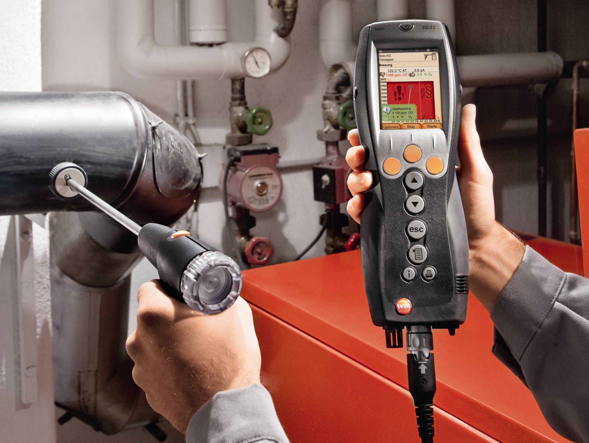
Любая топливосжигающая установка, независимо от используемой технологии, должна функционировать в оптимальном режиме. Вопросы о соблюдении соответствующих требований, сокращении расхода энергии и снижении объемов выбросов загрязняющих веществ сегодня имеют наивысший приоритет. Для того чтобы наиболее эффективно реализовать оптимизационный потенциал необходимо выполнять регулярные проверки работы и настройку систем отопления. Благодаря новым функциям обновленные версии анализаторов дымового газа testo 330-1 LL и testo 330-2 LL обеспечат Вам еще более профессиональную и надежную поддержку при настройке эксплуатационного режима систем отопления.
Новый цветной дисплей анализатора дымовых газов testo 330 LL визуализирует данные измерений графически: Не требующие пояснений графики, интуитивно понятные символы и цветная палитра отображения данных в значительной степени упрощают процедуру анализа данных измерений.
Преимущества нового анализатора дымовых газов testo 330 LL:
- Цветной дисплей с высокой разрешающей способностью для графического представления данных измерений
- Дополнительные меню измерения, например, «Твердое топливо» и «Проверка газовых труб», что позволяет выполнять всеобъемлющий анализ системы отопления
- Функция регистрации данных для легкой записи кривой измерений
Для Вашего удобства на нашем сайте представлен сравнительный обзор высокотехнологичных анализаторов дымовых газов – testo 310, testo 320 и testo 330 LL. Вы можете выбрать анализатор, полностью отвечающий Вашим измерительным задачам, и сделать свою работу максимально эффективной.
С подтвержденными метрологическими характеристиками и расширенными техническими данными можно ознакомиться в описании типа в Центре загрузки.
Комплект поставки
Анализатор дымовых газов testo 330-1 LL с сенсорами Longlife, с сенсором CO (без H2-компенсации 0…4000 ppm); с встроенной функцией измерения тяги и обнуления сенсоров, вкл. аккумулятор и заводской протокол калибровки
Технические данные
| Общие технические данные | |
|---|---|
|
Вес |
600 г (вкл. аккумулятор) |
|
Размеры |
270 x 90 x 65 мм |
|
Рабочая температура |
-5 … +45 °C |
|
Класс защиты |
IP40 |
|
Размер дисплея |
Размер дисплея: 240 х 320 |
|
Дисплей |
Цветной графический |
|
Источник питания |
Перезар. блочный аккумул.: 3.7В / 2,6 А-ч, блок питания 6 В / 1.2 A |
|
Память |
500 измер. значений |
|
Температура хранения |
-20 … +50 °C |
| Пьезорезистивный сенсор дифференциального давления | |
|---|---|
|
Диапазон измерений |
0 … +300 гПа |
|
Погрешность |
±0,5 гПа (0,0 … 50,0 гПа) ±1 % от изм. знач. (50,1 … 100,0 гПа) ±1,5 % от изм. знач. (в ост. диапазоне) |
|
Разрешение |
0,1 гПа |
| Измерение О₂ | |
|---|---|
|
Диапазон измерений |
0 … 21 % Об. |
|
Погрешность |
±0,2 % Об. |
|
Разрешение |
0,1 % Об. |
|
Быстродействие t90 |
< 20 с. |
| Измерение СО (с Н₂-компенсацией) | |
|---|---|
|
Диапазон измерений |
0 … 8000 ppm |
|
Погрешность |
±10 ppm или ±10 % от изм. знач. (0 … 200 ppm) ±20 ppm или ±5 % от изм. знач. (201 … 2000 ppm) ±10 % от изм. знач. (2001 … 8000 ppm) |
|
Разрешение |
1 ppm |
|
Быстродействие t90 |
< 60 с. |
|
Частота измерений |
0 … 500 ppm |
| Измерение СОниз (С Н₂-компенсацией) | |
|---|---|
|
Диапазон измерений |
0 … 500 ppm |
|
Погрешность |
±2 ppm (0 … 39,9 ppm) ±5 % от изм. знач. (40 … 500 ppm) |
|
Разрешение |
0,1 ppm |
|
Быстродействие t90 |
< 40 с. |
| Измерение NO | |
|---|---|
|
Диапазон измерений |
0 … 3000 ppm |
|
Погрешность |
±5 ppm (0 … 100 ppm) ±5 % от изм. знач. (101 … 2000 ppm) ±10 % от изм. знач. (2001 … 3000 ppm) |
|
Разрешение |
1 ppm |
|
Быстродействие t90 |
< 30 с. |
| Измерение NOниз | |
|---|---|
|
Диапазон измерений |
0 … 300 ppm |
|
Погрешность |
±2 ppm (0 … 39,9 ppm) ±5 % от изм. знач. (40 … 300 ppm) |
|
Разрешение |
0,1 ppm |
|
Быстродействие t90 |
< 30 с. |
| Измерение дифференциального давления (тяга дымового газа) | |
|---|---|
|
Диапазон измерений |
-9,99 … +40 гПа |
|
Погрешность |
±0,02 гПа или ±5 % от изм. знач. (-0,50 … +0,60 гПа) ±0,03 гПа (+0,61 … +3,00 гПа) ±1,5 % от изм. знач. (+3,01 … +40,00 гПа) |
|
Разрешение |
0,01 гПа |
| Измерение температуры | |
|---|---|
|
Диапазон измерений |
-40 … +1200 °C * |
|
Погрешность |
±0,5 °C (0 … +100,0 °C) ±0,5 % от изм. знач. (в ост. диапазоне) |
|
Разрешение |
0,1 °C (-40 … +999,9 °C) 1 °C (> +1000 °C) |
* Measuring range depends on the connected flue gas probe
| Определение КПД (Eta) | |
|---|---|
|
Диапазон измерений |
0 … 120 % |
|
Разрешение |
0,1 % |
| Определение потери тепла с дымовыми газами | |
|---|---|
|
Диапазон измерений |
0 … 99,9 % |
|
Разрешение |
0,1 % |
| Расчёт CO₂ (через O₂) | |
|---|---|
|
Диапазон измерений |
0 … CO₂ макс (Диапазон индикации) |
|
Погрешность |
±0,2 % Об. |
|
Разрешение |
0,1 % Об. |
|
Быстродействие t90 |
< 40 с. |
| Измерение давления | |
|---|---|
|
Диапазон измерений |
0 … +300 гПа |
|
Погрешность |
±0,5 гПа (0,0 … 50,0 гПа) ±1 % от изм. знач. (50,1 … 100,0 гПа) ±1,5 % от изм. знач. в ост. диапазоне |
|
Разрешение |
0,1 гПа |
| Измерение СО (без Н₂-компенсации) | |
|---|---|
|
Диапазон измерений |
0 … 4000 ppm |
|
Погрешность |
±20 ppm (0 … 400 ppm) ±5 % от изм. знач. (401 … 2000 ppm) ±10 % от изм. знач. (2001 … 4000 ppm) |
|
Разрешение |
1 ppm |
|
Быстродействие t90 |
< 60 с. |
| Измерение СО в окружающей среде | |
|---|---|
|
Диапазон измерений |
0 … 500 ppm |
|
Погрешность |
±5 ppm (0 … 100 ppm) ±5 % от изм. знач. (> 100 ppm) |
|
Разрешение |
1 ppm |
|
Быстродействие |
Около 35 с. |
зондом CO 0632 3331
| Измерение CO₂ в окружающей среде | |
|---|---|
|
Диапазон измерений |
0 … 1 % Об. 0 … 10000 ppm |
|
Погрешность |
±75 ppm или ±3 % от изм. знач. (0 … 5000 ppm) ±150 ppm или ±5 % от изм. знач. (5001 … 10000 ppm) |
|
Быстродействие |
Около 35 с. |
зондом измер. CO₂ в окр.среде 0632 1240
| Обнаружение и локализация утечек горючих газов | |
|---|---|
|
Диапазон измерений |
0 … 10000 ppm CH₄ / C₃H₈; Диапазон индикации |
|
Погрешность |
Тип сигнала:оптическое оповещение(LED) звуковое оповещение(зуммер) |
|
Быстродействие t90 |
< 2 с. |
зондом-течеискателем 0632 3330
Зонды
Зонды
152,00 y.e.
c НДС. Внутренний курс у.е. равен 89 рублям
Комплекты
Комплекты приборов
1,815,00 y.e.
c НДС. Внутренний курс у.е. равен 89 рублям
2,053,00 y.e.
c НДС. Внутренний курс у.е. равен 89 рублям
Принадлежности
Приборы / опции
439,00 y.e.
c НДС. Внутренний курс у.е. равен 89 рублям
Применение
Измерение концентрации CO в окружающей среде
Угарный газ (CO) – не имеющий цвета и запах ядовитый газ, являющийся продуктом неполного сгорания топлива, в составе которого есть углерод (нефть, газ и твердые виды топлива). При попадании угарного газа в кровь через легкие он активно связывается с гемоглобином, блокируя передачу кислорода тканевым клеткам, в результате удушья наступает смерть. Таким образом, крайне важно контролировать концентрацию CO в горячей точке дымовых газов, в местах размещения топливосжигающих установок для систем горячего водоснабжения, а также в других прилегающих помещениях.

Измерение давления (давление газа в форсунке, давление газового потока)
Базовые измерения при настройке систем отопления жилых помещений включают проверку давления газа, в которую, в свою очередь, входит измерение давления газового потока и статического давления газа. Измерение давления потока газа подразумевает измерение давления в подающей трубе, а при измерениях статического давления определяется распределение давления в покоящемся газе. Если значение давления потока газа газовых котлов выходит за пределы диапазона от 18 до 25 мбар, эксплуатация не допустима. Если, несмотря на несоответствие значений, эксплуатация осуществляется, нарушается функциональность горелки, и при регулировке пламени может произойти взрыв, что ведет к выходу из строя горелки, а, значит – и всей отопительной системы.
Измерения дымовых газов для наладки горелок (CO, O2 и температура)
Измерения параметров дымовых газов для проверки в системах отопления позволяют определить количество загрязняющих веществ, выбрасываемых в окружающую среду с дымовыми газами (напр., монооксид углерода – CO или диоксид углерода – CO2), а также рассчитать потери тепла с дымовыми газами. В некоторых странах требования к измерению дымовых газов прописаны в законодательстве. Принятие подобных законов преследует две основные цели:
1. Максимально возможное сокращение выбросов загрязняющих веществ в атмосферу;
2. Эффективное использование энергии.
Запрещается превышать установленные предельно допустимые значения загрязняющих веществ в атмосфере.
Контроль соответствия измеренных значений предельно допустимым осуществляется в режиме нормальной эксплуатации (измерения проводят с помощью соответствующих приборов перед каждым запуском системы). Для измерений конец трубки зонда отбора пробы помещается в центр дымохода, где температура и концентрация дымовых газов наиболее высокая. Данные измерений регистрируются анализатором дымовых газов, а затем могут быть переданы на печать или на ПК для дальнейшей обработки и анализа.
Измерения проводятся монтажником систем отопления в ходе пуско-наладочных работ, а затем, при необходимости, через четыре недели после ввода в эксплуатацию – инженером по очистке дымовых труб или представителем органа надзора. В дальнейшем, через установленные интервалы времени, осуществляются регулярные измерения, проведением которых занимается уполномоченный инженер по сервисному обслуживанию.
Измерение температуры на радиаторах
При проведении измерений на радиаторах, инженер по сервисному обслуживанию, в частности, определяет температуру среды в подающем и обратном трубопроводе. Иными словами, проводится измерение температуры подачи и возврата теплоносителя (напр., вода), за счет которой происходит процесс переноса тепла в текучей среде. Для того чтобы избежать потерь тепла в распределительной тепловой сети и обеспечить надлежащий уровень эффективности, необходимо проводить регулярные точечные замеры температуры в подающем и обратном трубопроводе. Для настройки систем отопления необходима гидравлическая регулировка, для осуществления которой необходимо знать температуру среды в подающем и обратном трубопроводе. В соответствии с этим, в отопительных системах для всех радиаторов или контуров отопления устанавливается необходимое значение температуры среды в подающем трубопроводе, а также точно определяется количество теплоносителя. Таким образом, достигается значение температуры окружающего воздуха, требуемое для каждого конкретного помещения. Нарушения условий эксплуатации ведут к перерасходу электрической и тепловой энергии. В Германии в соответствии с Федеральным постановлением об энергосбережении (EnEV) при пуско-наладке систем отопления обязательной является гидравлическая регулировка.
Центр загрузки
Брошюры по продукту
-
Каталог Анализаторы дымовых газов 2022
(application/pdf, 16.318 KB) -
Свидетельство testo 330-1LL, testo 330-2LL
(application/pdf, 6.420 KB) -
Описание типа testo 330 LL
(application/pdf, 5.742 KB)
Инструкции по применению
-
Инструкция по использованию testo 330LL
(application/pdf, 1.866 KB)
Программное обеспечение
-
Software EasyHeat for testo 300, 312-4, 320, 324, 330, 380
(font/x-font-fon, 105.927 KB)
Если у Вас уже установлено ПО testo easyheat, то текущая версия будет обновлена до версии. Возможно обновление любой версии ПО testo easyheat. Данная версия может быть также использована в качестве демо-версии, если ПО testo easyheat еще не установлено на Вашем компьютере. Срок действия демо-версии составляет 30 дней.
-
Update-Kit / Bootloader
(V1.22, EXE, 381 KB)
If the firmware update does not start under Windows 8.1 or Windows 10, a new bootloader must be installed on the measuring device once.
A description and all necessary files can be found under the search term: Update-Kit / Bootloader -
Testo ZIV драйвер версия ZIV 2000 для testo 320, testo 330
(ZIP, 8.8 MB)
Testo 300, 320, 330 ZIV драйвер позволяет подключать анализаторы дымовых газов testo 300, 330 к программному обеспечению сторонних производителей. Драйвер соответствует новому постановлению BImSchV, действительному с 22 марта 2010
-
Testo ZIV драйвер версия для testo 300, testo 320, testo 330
(v2.3, ZIP, 8.7 MB)
Testo 300, 320, 330 ZIV драйвер позволяет подключать анализаторы дымовых газов testo 300, 330 к программному обеспечению сторонних производителей. Драйвер соответствует новому постановлению BImSchV, действительному с 22 марта 2010
-
Firmware (testo 330-1 LL v2010, 330-2 LL v2010, 330-1 LX, 330-2 LX, 380)
(V2.25, application/octet-stream, 13.953 KB)
If the firmware update does not start under Windows 8.1 or Windows 10, a new bootloader must be installed on the measuring device once.
A description and all necessary files can be found under the search term: Update-Kit / Bootloader
Посмотреть инструкция для Testo 330-1 LL бесплатно. Руководство относится к категории измерительные приборы, 1 человек(а) дали ему среднюю оценку 7.8. Руководство доступно на следующих языках: русский. У вас есть вопрос о Testo 330-1 LL или вам нужна помощь? Задайте свой вопрос здесь
Не можете найти ответ на свой вопрос в руководстве? Вы можете найти ответ на свой вопрос ниже, в разделе часто задаваемых вопросов о Testo 330-1 LL.
Инструкция Testo 330-1 LL доступно в русский?
Не нашли свой вопрос? Задайте свой вопрос здесь
![]()
testo 330 -1, -2, -3 / testo 330 -1 , -2
, -2 Flue gas analyser
2 General notes
General notes
Please read this documentation through carefully and familiarise yourself with the operation of the product before putting it to use. Keep this document to hand so that you can refer to it when necessary.
The document describes the country-specific version D of the testo 330-1, -2, -3 and testo 330-1 LL, -2 LL products.
Identification
|
Symbol |
Meaning |
Comments |
|
Warning advice: Warning! |
Read the warning advice carefully and take |
|
|
Serious physical injury could be caused if the |
the specified precautionary measures! |
|
|
specified precautionary measures are not taken. |
Warning advice: Caution!
Slight physical injury or damage to equipment could occur if the specified precautionary measures are not taken.
Read the warning advice carefully and take the specified precautionary measures!
|
Important. |
Please pay particular attention. |
|
|
(testo 330-1) |
The description applies only for the |
— |
|
instrument indicated: testo 330-1, -2, -3 / |
||
|
testo 330-1LL, -2LL. |
||
|
Text |
Text appears on the instrument’s display |
— |
|
Key |
Press the key. |
|
|
OK |
Function key with the function “OK”. |
Press function key. |
|
xyz |
Short form for operating steps. |
See short form, p. 3. |
General notes 3
Short form
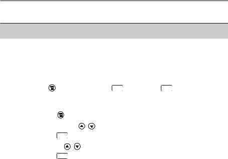
This document uses a short form for describing operating steps (e.g. calling up a function).
Example: Calling up the Flue gas function
|
Short form: |
Measurements |
OK |
Flue gas OK |
||
|
(1) |
(2) |
(3) |
(4) |
(5) |
|
|
Steps required: |
|||||
|
1 |
Open main menu: |
. |
|||
|
2 |
Select Measurements menu: , . |
||||
|
3 |
Confirm selection: |
OK . |
|||
|
4 |
Select Flue gas menu: , . |
||||
|
5 |
Confirm selection: |
OK . |
4 Contents
Contents
See also Functional overview, p. 63.
|
General notes |
……………………………………………………………………………. |
2 |
||
|
Contents …………………………………………………………………………………… |
4 |
|||
|
A. |
Safety advice |
……………………………………………………………………………. |
7 |
|
|
B. |
Intended purpose ………………………………………………………………………. |
9 |
||
|
C. |
Product description …………………………………………………………………. |
10 |
||
|
C.1 |
Measuring instrument ………………………………………………………… |
10 |
||
|
C.1.1 |
Overview ………………………………………………………………………. |
10 |
||
|
C.1.2 |
Keypad ………………………………………………………………………… |
11 |
||
|
C.1.3 |
Display ………………………………………………………………………… |
11 |
||
|
C.1.4 |
Device connections ………………………………………………………… |
12 |
||
|
C.1.5 |
Interfaces …………………………………………………………………….. |
13 |
||
|
C.1.6 |
Components …………………………………………………………………. |
13 |
||
|
C.1.7 |
Carrying strap / barcode pen holder …………………………………… |
14 |
||
|
C.2 |
Modular flue gas probe ………………………………………………………. |
15 |
||
|
D. |
Commissioning ………………………………………………………………………… |
16 |
||
|
E. |
Operation ……………………………………………………………………………….. |
17 |
||
|
E.1 |
Mains unit / rechargeable battery ………………………………………….. |
17 |
||
|
E.1.1 |
Changing the battery …………………………………………………….. |
17 |
||
|
E.1.2 |
Charging batteries ………………………………………………………….. |
18 |
||
|
E.1.3 |
Operation with the mains unit ………………………………………….. |
18 |
||
|
E.2 |
Probes / Sensors ……………………………………………………………….. |
19 |
||
|
E.2.1 |
Connecting probes / sensors ……………………………………………. |
19 |
||
|
E.2.2 |
Replacing the probe module ……………………………………………. |
20 |
||
|
E.3 |
Regular care …………………………………………………………………….. |
20 |
|
E.3.1 |
Condensate trap ……………………………………………………………. |
20 |
|
E.3.2 |
Checking / replacing the particle filter …………………………………. |
21 |

Contents 5
|
E.4 |
Basic operating steps ………………………………………………………… |
21 |
||
|
E.4.1 |
Switching the measuring instrument on ……………………………… |
21 |
||
|
E.4.2 |
Calling up a function ………………………………………………………. |
22 |
||
|
E.4.3 |
Entering values ……………………………………………………………… |
22 |
||
|
E.4.4 |
Printing data …………………………………………………………………. |
23 |
||
|
E.4.5 |
Saving data …………………………………………………………………… |
23 |
||
|
E.4.6 |
Confirming an error message ………………………………………….. |
23 |
||
|
E.4.7 |
Scanning locations with the barcode pen ………………………….. |
24 |
||
|
E.4.8 |
Switching the measuring instrument off ……………………………… |
24 |
||
|
E.5 |
Memory / Location ……………………………………………………………… |
25 |
||
|
E.6 |
Instrument diagnosis ………………………………………………………… |
27 |
||
|
F. |
Configuration |
………………………………………………………………………….. |
28 |
|
|
F.1 |
Instrument settings ……………………………………………………………. |
28 |
||
|
F.1.1 |
Display edit …………………………………………………………………… |
28 |
||
|
F.1.2 |
Printer ………………………………………………………………………….. |
29 |
||
|
F.1.3 |
Alarm limits …………………………………………………………………… |
30 |
||
|
F.1.4 |
Start Keys edit ……………………………………………………………… |
30 |
||
|
F.1.5 |
t315-3 Connect ……………………………………………………………… |
31 |
||
|
F.1.6 |
Communication ……………………………………………………………… |
32 |
||
|
F.1.7 |
Date / Time …………………………………………………………………… |
32 |
||
|
F.1.8 |
Language …………………………………………………………………….. |
32 |
||
|
F.2 |
Sensor settings …………………………………………………………………. |
33 |
||
|
F.3 |
Fuels ……………………………………………………………………………… |
34 |
||
|
G. |
Measuring ……………………………………………………………………………….. |
35 |
||
|
G.1 |
Preparing measurements …………………………………………………… |
35 |
||
|
G.1.1 |
Zeroing phases ……………………………………………………………… |
35 |
||
|
G.1.2 |
Using the modular flue gas probe …………………………………….. |
36 |
||
|
G.1.3 |
Configuring the reading display ………………………………………… |
36 |
||
|
G.1.4 |
Set memory/location ………………………………………………………. |
36 |

6 Contents
|
G.2 |
Measurements …………………………………………………………………. |
37 |
||
|
G.2.1 |
Flue gas ………………………………………………………………………. |
37 |
||
|
G.2.2 |
Draught ………………………………………………………………………… |
38 |
||
|
G.2.3 |
Fine pressure probe (accessory) ………………………………………. |
38 |
||
|
G.2.4 |
BImSchV (testo 330-3 / testo 330-2 LL) ……………………………. |
39 |
||
|
G.2.5 |
Solid fuel measurement (testo 330-2) …………………………………. |
41 |
||
|
G.2.6 |
CO undiluted …………………………………………………………………. |
42 |
||
|
G.2.7 |
Smoke No. / HCT ………………………………………………………….. |
42 |
||
|
G.2.8 |
Differential pressure ………………………………………………………… |
43 |
||
|
G.2.9 |
Differential temperature …………………………………………………… |
44 |
||
|
G.2.10 |
O2 air ………………………………………………………………………….. |
44 |
||
|
G.2.11 |
Gas flow rate ……………………………………………………………….. |
45 |
||
|
G.2.12 |
Oil flow rate …………………………………………………………………… |
45 |
||
|
G.2.13 |
Leak detection ……………………………………………………………… |
46 |
||
|
G.2.14 |
Ambient CO …………………………………………………………………. |
46 |
||
|
G.2.15 |
Ambient CO2 ……………………………………………………………….. |
47 |
||
|
G.2.16 |
Burner control ……………………………………………………………….. |
48 |
||
|
I. |
Transfering data ………………………………………………………………………. |
50 |
||
|
H.1 |
Protocol printer …………………………………………………………………. |
50 |
||
|
H.2 |
PC / Pocket PC …………………………………………………………………. |
50 |
||
|
I. |
Care and maintenance ……………………………………………………………… |
51 |
||
|
I.1 |
Cleaning the measuring instrument ………………………………………. |
51 |
||
|
I.2 |
Replacing measuring cells …………………………………………………. |
51 |
||
|
I.3 |
Recalibrating measuring cells ……………………………………………… |
52 |
||
|
I.4 |
Replacing additional filter …………………………………………………… |
52 |
||
|
I.5 |
Cleaning the modular flue gas probe …………………………………….. |
53 |
||
|
I.6 |
Changing the thermocouple ……………………………………………….. |
53 |
||
|
J. |
Questions and Answers ……………………………………………………………. |
54 |
||
|
K. |
Technical data ………………………………………………………………………… |
55 |
||
|
K.1 |
Standards and inspections …………………………………………………. |
55 |
||
|
K.2 |
Measuring ranges and accuracies ………………………………………. |
56 |
||
|
K.3 |
Other device data ……………………………………………………………… |
57 |
||
|
K.4 |
EC declaration of conformity ……………………………………………….. |
58 |
||
|
K.5 |
Principles of calculation …………………………………………………….. |
59 |
||
|
K.5.1 |
Fuel parameters ……………………………………………………………. |
59 |
||
|
K.5.2 |
Calculation formulae ………………………………………………………. |
59 |
|
L. Accessories/Spare parts |
…………………………………………………………..61 |
|
Functional overview …………………………………………………………………. |
63 |
A. Safety advice 7
A. Safety advice
 Avoid electrical hazards:
Never use the measuring instrument and probes to measure on or near live parts!
 Protect the measuring instrument:
Never store the instrument / measuring cells together with solvents (e.g. acetone). Do not use any dessicants.
 Product with Bluetooth® (Option)
Changes or modifications, which are not expressly approved by the responsible official body, can lead to a withdrawal of operating permission.
Interference with data transfer can be caused by instruments which transmit on the same ISM band, e.g. microwave ovens, ZigBee.
The use of radio connections is not allowed in e.g. aeroplanes and hospitals. For this reason, the following point must be checked before entering:
Deactivate Bluetooth function:
 Inst’ settings OK Communication OK IrDA OK .
 Product safety / preserving warranty claims:
Operate the measuring instrument only within the parameters specified in the technical data.
Handle the instrument properly and according to its intended purpose.
Never apply force!
Temperatures given on probes / sensors relate only to the measuring range of the sensors. Do not expose handles and feeders to any temperatures in excess of 70 °C unless they are expressly permitted for higher temperatures.
Open the measuring instrument only when this is expressly described in the Operating Instructions for maintenance purposes.
Carry out only the maintenance and repair work that is described in the Operating Instructions. Follow the prescribed steps exactly. For safety reasons, use only original spare parts from Testo.
The testo 330 must be checked before commissioning for any visible damage. Do not commission the testo 330 if there are signs of damage on the housing, mains unit or supply lines. Electrical risk..
8 A. Safety advice
Any further or additional work must only be carried out by authorised personnel. Testo will otherwise refuse to accept responsibility for the proper functioning of the measuring instrument after repair and for the validity of certifications.

 Ensure correct disposal:
Dispose of defective rechargeable batteries and spent batteries at the provided collection points.
Send the measuring instrument directly to us at the end of its life cycle. We will ensure that it is disposed of in an environmentally friendly manner.

B. Intended purpose 9
B. Intended purpose
This chapter describes the areas of application for which the measuring instrument is intended.
The testo 330 is a handheld measuring device for the professional flue gas analysis of furnace systems:
·Small furnaces (burning oil, gas, wood, coal)
·Low-temperature and condensing boilers
·Gas heaters
These systems can be adjusted using the testo 330 and checked for compliance with the applicable limit values.
The measuring instrument is approved for measurements under the German regulations on immissions protection (1. BImSchV).
The following tasks can also be carried out with the testo 330:
·Regulating the O2-, COand CO2-, NO-, NOx values in furnaces for the purpose of ensuring optimal operation.
·Draught measurement.
·Measuring and regulating the gas flow pressure in gas heaters.
·Measuring and optimising the flow and return temperatures of heating systems.
·COand CO2 environment measurement.
·Detection of CH4 (methane) and C3H8 (propane).
testo 330 should not be used:
·for continuous measurements
·as a safety (alarm) instrument
The testo 330 with the Bluetooth option may only be operated in countries in which it is type approved (see Technical Data).
10C. Product description C.1 Measuring instrument
C. Product description
This chapter provides an overview of the individual components of the product.
C.1 Measuring instrument
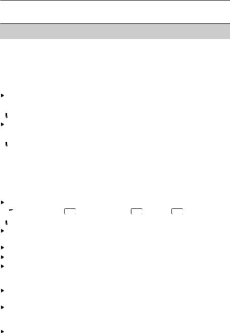
C.1.1 Overview
Placeholder:
Uebersicht.tif
Switch on / off
Interfaces: USB, PS2, infrared Do not direct infrared beam at  human eyes.
|
Condensate trap (on rear) |
||
|
Fixing eyelets for carrying strap (left and |
||
|
right) |
||
|
Display |
||
|
Magnetic holders (on rear) |
|
Strong magnets |
|||||
|
Damage to other magnets |
|||||
|
Keep safe distance from |
|||||
|
products which could be |
|||||
|
damaged by magnets (e.g. |
|||||
|
monitors, computers, |
|||||
|
pacemakers, credit cards). |
|||||
|
Keypad |
|||||
|
Service cover (on rear) |
|||||
|
Gas outlet |
|||||
|
Unit connections: flue gas probe, |
|||||
|
probe, pressure probe, mains unit |

C. Product description 11
C.1 Measuring instrument
C.1.2 Keypad
Key Functions
Switch measuring instrument on/off
Function key (orange, 3x), relevant function is shown on the display
Scroll up, increase value
Scroll down, reduce value
Back, cancel function
Open Main menu: press briefly (changed settigs are stored, measurement values are carried over into the menu Flue gas); open Measurements menu: press and hold down for 2s (changed settigs are stored, measurement
values are carried over into the menu Flue gas)
Open Inst’ diagnosis menu
Switch over display light: display light is permanently on or display light goes on for 10 seconds everytime a key is activated.
C.1.3 Display
Depending on the menu that is active, the display shows a variety of elements.
Header (active in all views)
Warning symbol (only if there is a device error; the
device error is displayed in the Inst’ diagnosis menu).
Active location.
Power supply symbol:
|
Symbol |
Characteristic |
Symbol |
Characteristic |
||||
|
Mains operation |
Rech. battery operation, capacity: 26-50% |
||||||
|
Rech. battery operation, capacity: 76-100% |
Rech. battery operation, capacity: 6-25% |
||||||
|
Rech. battery operation, capacity: 51-75% |
Rech. battery operation, capacity: 0-5% |
Function select view
Active menu, activated fuel
Selection field for functions:
The chosen function is shown with a grey background.
Unavailable functions are written in grey type.
Scroll bar
Function keys for entering commands

12C. Product description C.1 Measuring instrument
Settings view
Active menu
Function fields for entering commandsScroll bar
Selection field for adjustable values: The chosen value is shown with a grey
background. Unavailable values are written in grey type.
Function keys for entering commands
Active menu, depending on the chosen function: Additional information (e.g. activated fuel,
date and time)
Scroll bar
Display field for readings, parametersFunction keys for entering commands
C.1.4 Device connections
Probe socketFlue gas socket
Mains unit socketPressure socket
C. Product description 13
C.1 Measuring instrument
C.1.5 Interfaces
|
USB interface: |
|||||||
|
connection to PC |
|||||||
|
PS2 interface: |
|||||||
|
connection to barcode pen, adapter for automatic |
|||||||
|
furnaces |
|||||||
|
Infrared interface (IrDA): connection to Ir/IrDA |
|||||||
|
printers / Pocket PC |
|||||||
|
Bluetooth interface (option): connection to |
|||||||
|
Bluetooth printers / Pocket PC |
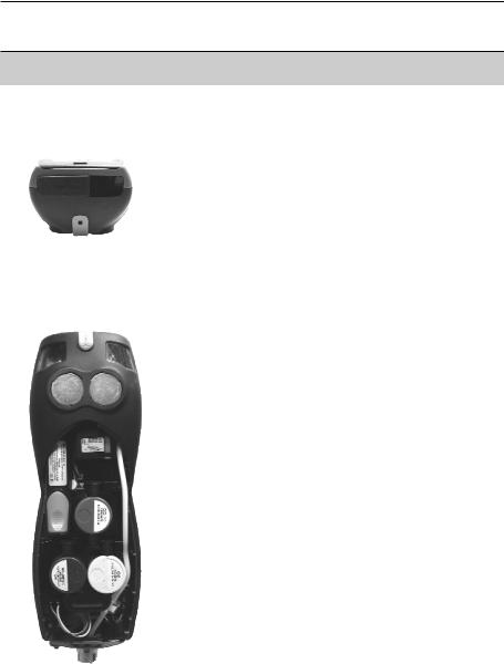
C.1.6 Components
Rechargeable batteryMeasuring gas pump
Slot for CO measuring cellSlot for O2 measuring cell
Slot for NO-, NO low measuring cellAdditional filter
14C. Product description C.1 Measuring instrument
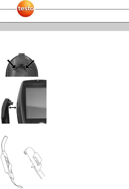
C.1.7 Carrying strap/barcode pen holder
To secure the carrying strap:
1Remove sealing caps from the sides of the housing.
Fix sealing caps on the inside of the service cover: 1 Place the measuring instrument on its front.
2 Pick the service cover up at the markings (arrows) using your index finger and thumb and press gently to release the lock.
3 Fold the service cover up and remove it.
4Secure the sealing caps in the two holders on the inside of the service cover ( ).
5 Attach the service cover and engage it in place.
2Engage the carrying strap clip in the fixing eyelets on the side of the device. Note the guide groove. The strap must point “down” ( ).
To secure the barcode pen holder to the carrying strap:
1Loosen the carrying strap at the buckle and remove.
2 Lead carrying strap through the strap guide of the barcode pen holder ( ).
3Lead carrying strap through the buckle ( ) and tighten.

|
C. Product description |
15 |
|
C.2 Modular flue gas probe |
C.2 Modular flue gas probe
|
Removable filter chamber with window and particle |
||||||||||||
|
filter |
||||||||||||
|
Probe handle |
||||||||||||
|
Connecting cable |
||||||||||||
|
Connecting plug for measuring instrument |
||||||||||||
|
Probe module lock release |
||||||||||||
|
Probe module |
16 D. Commissioning
D. Commissioning
This chapter describes the steps required to commission the product.
Remove the protective film from the display.
The measuring instrument is supplied with a rechargeable battery already fitted.
Charge the battery up fully before using the instrument (see Charging batteries, p. 18).
E. Operation 17
E.1 Mains unit / rechargeable battery
E. Operation
This chapter describes the steps that have to be executed frequently when using the product.
Please read this chapter carefully. The following chapters of this document will assume you are already familiar with the content of this chapter.
E.1 Mains unit/rechargeable battery
If the mains unit is connected, the measuring instrument is automatically powered from the unit. It is not possible to charge the battery in the instrument during operation.
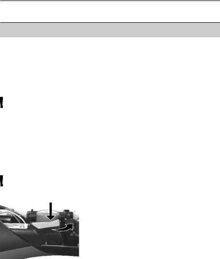
E.1.1 Changing the battery
The measuring instrument must not be connected to a mains socket via the mains unit. The instrument must be switched off. Change the rechargeable battery within 60 minutes so that device settings (e.g. date / time) are not lost.
1 Place the measuring instrument on its front.
2Remove the service cover: Take hold of it at the markings (arrows) using the index finger and thumb, press slightly, fold up and remove.
3Open the battery lock: Press the orange key and push in the direction of the arrow.
4Remove the battery and insert a new rechargeable battery. Only use the Testo rechargeable battery 0515 0100.
5Close battery lock: Press the orange key and push against the direction of the arrow until the battery engages.
6 Attach the service cover and engage it in place.
18E. Operation
E.1 Mains unit / rechargeable battery
E.1.2 Charging batteries
The rechargeable battery can only be charged at an ambient temperature of ±0 to +35 °C. If the battery has discharged completely, the charging time at room temperature is approximately 5-6 h.
Charging in the measuring instrument
The instrument must be switched off.
1Connect the plug of the mains unit to the mains unit socket on the measuring instrument.
2 Connect the mains plug of the mains unit to a mains socket.
—The charging process will start. The charge condition will be shown on the display. The charging process will stop automatically when the battery is fully charged.
Recharging in the charging station (0554 1087)
Refer to the documentation enclosed with the charging station.
Battery care
If possible, always discharge the battery and recharge it fully.
Do not store the battery for long periods when discharged. (The best storage conditions are at 50-80% charge level and 10-20 °C ambient temperature; charge fully before further use).
E.1.3 Operation with the mains unit
1Connect the plug of the mains unit to the mains unit socket on the measuring instrument.
2 Connect the mains plug of the mains unit to a mains socket.
—The measuring instrument is powered via the mains unit.
—If the instrument is switched off and a rechargeable battery is inserted, the charging process will start automatically. Switching the instrument on has the effect of stopping battery charging and the instrument is then powered via the mains unit.
E. Operation 19
E.2 Probes / Sensors
E.2 Probes/Sensors
E.2.1 Connecting probes/sensors
Probe socket:
Probe detection is carried out at the socket during the initial switch on activation process: Probes that are required must always be connected before the measuring instrument is switched on, or the instrument must be switched off and then on again after a change of probe, so that the correct data can be read into the instrument.
Flue gas socket:
Probe / sensor detection at the flue gas socket is carried out continuously. It is possible to change the probe / sensor even while the measuring instrument is switched on.
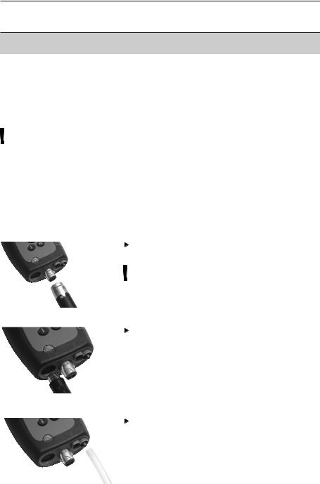
Connect flue gas probes/gas pressure adapters/temperature adapters
Insert the connector into the flue gas socket and lock by turning it clockwise gently (bayonet lock).
Only one hose extension (0554 1201) should be connected between the measuring instrument and the flue gas probe.
Connecting other probes
Insert the connector of the probe into the probe socket.
Connecting the pressure hose
Fit the pressure hose on the connecting nipple of the pressure socket.
20E. Operation E.3 Regular care
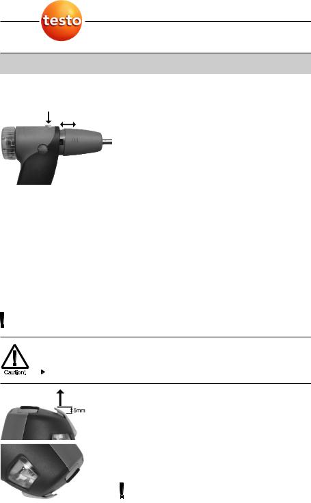
E.2.2 Replacing the probe module
1Press the key on the top of the probe handle and remove the probe module.
2 Fit a new probe module and engage it in place.
E.3 Regular care
E.3.1 Condensate trap
The fill level of the condensate trap can be read from the markings on the trap.
A warning message ( red flashing light) is displayed if the level in the condensate trap reaches 90%.
Emptying the condensate trap
The condensate consists of a weak mix of acids. Avoid contact with the skin. Make sure that the condensate does not run over the housing.
Condensate in gas path.
Damage to measuring cells and flue gas pump.
Do not empty condensate trap while pump is operating.
1Hold the measuring instrument so that the
condensate outlet points up.
2Open condensate outlet in condensate trap: Pull out approx. 5mm or until it will not go any further ( ).
3 Let the condensate run out into a sink ( ).
4 Dab off drops at condensate outlet using a cloth. 5 Close the condensate outlet.
The condensate outlet must be fully closed (marking) otherwise incorrect measurements due to
![]()
E. Operation 21
E.4 Basic operating steps
inleaking air may result.
E.3.2 Checking/replacing the particle filter
Checking the particle filter:
Particle filters of the modular flue gas probe must be checked regularly for contamination:
Check visually by looking through the window of the filter chamber.
Replace the filter if there are signs of contamination.
Replacing the particle filter:
Filter chamber may contain condensate.
1Open the filter chamber: Turn gently anticlockwise.
2Remove the filter plate and replace it with a new one (0554 3385).
3Fit the filter chamber and lock it: Turn gently clockwise.
E.4 Basic operating steps
E.4.1 Switching the measuring instrument on
 .
.
—The start screen is displayed (for about 5 s).
—Display illumination is switched on for 10 s. Option:
 To go directly to a measurement while the start screen is being displayed, press the function key for the desired measurement. See also Start key configuration, p. 30.
— The Measurements menu is opened. -or-
—If another probe / sensor is connected rather than a flue gas probe: the measuring menu for that probe / sensor is opened.
 Loading…
Similar to TESTO 330-1 LL Manuals, User Guides and Instructions:
-
Fluke 744
®744Documenting Process CalibratorUsers ManualPN 691287September 1998 Rev.1, 2/99© 1998,1999 Fluke Corporation. All rights reserved. Printed in U.S.A.All product names are trademarks of their respective companies. …
744 Multimeter, 138
-
SICK DL100 Pro
Chipsmall Limited consists of a professional team with an average of over 10 year of expertise in the distributionof electronic components. Based in Hongkong, we have already established firm and mutual-benefit businessrelationships with customers from,Europe,America and south Asia,supplying obsolete and hard-to-find c …
DL100 Pro Analytical Instruments, 26
-
Young 86004
METEOROLOGICAL INSTRUMENTSINSTRUCTIONSR.M. YOUNG COMPANY 2801 AERO PARK DRIVE, TRAVERSE CITY, MICHIGAN 49686, USATEL: (231) 946-3980 FAX: (231) 946-4772 WEB: www.youngusa.com PN: 86004-90 REV: G092117ULTRASONIC ANEMOMETERMODEL 86004 …
86004 Measuring Instruments, 12
-
Vernier COL-BTA
Colorimeter(Order Code COL-BTA)The Vernier Colorimeter is used to determine th econcentration of a solution by analyzing its colorintensity. The cuvette slot is designed toaccommodate most cuvett es w ith a 10 millimeterpath length. The Colorimeter measures the amount of light transmitted through asample at a user-sele …
COL-BTA Measuring Instruments, 2