-
Руководства по ремонту
1
-
Инструкции по эксплуатации
1

Toshiba e-STUDIO181 инструкция по эксплуатации
(138 страниц)
- Языки:Русский
-
Тип:
PDF -
Размер:
5.55 MB -
Описание:
Многофункциональное устройство (МФУ)
Просмотр
На NoDevice можно скачать инструкцию по эксплуатации для Toshiba e-STUDIO181. Руководство пользователя необходимо для ознакомления с правилами установки и эксплуатации Toshiba e-STUDIO181. Инструкции по использованию помогут правильно настроить Toshiba e-STUDIO181, исправить ошибки и выявить неполадки.
Specifications:244/244826-estudio181.pdf file (25 Jan 2023) |
Accompanying Data:
Toshiba e-STUDIO181 All in One Printer, Speakers PDF Operator’s Manual (Updated: Wednesday 25th of January 2023 07:53:41 AM)
Rating: 4.8 (rated by 62 users)
Compatible devices: MJ-1027, 2500c, E-STUDIO151, TY-WSP200, e-STUDIO350, MJ-1028, E-studio 2050c, e-STUDIO6540C.
Recommended Documentation:
Text Version of Operator’s Manual
(Ocr-Read Summary of Contents of some pages of the Toshiba e-STUDIO181 Document (Main Content), UPD: 25 January 2023)
-
87, Replacing Toner Cartridge 85 Replacing Toner Cartridge When the toner in the toner cartridge has run out, replace the toner cartridge following the pro- cedure below. y Before inserting a new toner cartridge, check the product name of the cartridge. If you can see “T-1810”, this cartridge is usable.…
-
65, Copying Both Sides of Card into 1 Page — ID CARD — 63 Copying Both Sides of Card into 1 Page — ID CARD — The both sides of a card-sized original can be copied into one side of LT paper. This function is useful when you need to copy massive amounts of 2-sided cards. 1 Place paper in the drawer. …
-
4, Toshiba e-STUDIO181 2 Notice to Users Notice to Users FCC NOTICE This equipment has been tested and found to comply with the limits for a Class A digital device, pursuant to Part 15 of the FCC Rules. These limits are designed to provide reasonable protection against harmful interference when the equipment is operated in a commer…
-
29, Toshiba e-STUDIO181 Preparation 1 — Turning Power ON 27 Preparation 1 — Turning Power ON Turning power ON 1 Press the power switch to “ ” (ON) side. The equipment starts warming itself up. The warm-up time takes approx. 25 seconds. When the warm-up has finished, the [START] lamp is lit to show that the equipment is ready f…
-
32, 1 PREPARATION 30 Preparation 2 — Placing Copy Paper Preparation 2 — Placing Copy Paper Place copy paper in an appropriate paper source before you start copying. Acceptable media types Standard size plain paper (17 to 20 lb. Bond) can be used for the drawers in the equipment and the Paper Feed Unit (optional). Se…
-
Toshiba e-STUDIO181 User Manual
-
Toshiba e-STUDIO181 User Guide
-
Toshiba e-STUDIO181 PDF Manual
-
Toshiba e-STUDIO181 Owner’s Manuals
Recommended: HeatDish Plus, NV-DCF3 Series, TX-26LM70FA
-
Lexmark E260
Lexmark E260, E260d, andE260dn SeriesUser’s GuideMay 2008 www.lexmark.comLexmark and Lexmark with diamond design are trademarks of Lexmark International, Inc., registered in the United States and/or other countries.All other trademarks are the property of their respective owners.© 2008 Lexmark International, …
E260 156
-
Lexmark CX310 series
Quick ReferenceLearning about the printerUsing the printer control panel12345678910Use the To1 Display• View printing, copying, e‑mailing, andscanning options.• View printer status and error messages.2 Select button• Select menu options.• Save settings.3 Arrow buttons Scroll through menus or settings …
CX310 series 16
-
Konica Minolta bizhub 652
Copy OperationsUser’s GuideUser’s Guide*XXXXXXXX00**XXXXXXXX00*Konica Minolta Business Solutions Europe GmbHEuropaallee 17 30855 Langenhagen • GermanyTel.: +49 (0) 511 74 04-0Fax: +49 (0) 511 74 10 50www.konicaminolta.eu© 2009 Konica MinoltaBusiness Solutions Europe GmbHAll rights reserved. Pr …
bizhub 652 294
-
Kyocera TASKalfa 650c
6LH09633000 (1/4)2009.8305JN56811 According to the equipment model, these illustrations may differ from the appearances. 適用される機体のモデルによって、イラストと外観が異なることがあります。 Selon le modèle, il est possible que ces illustrations changent. Je nach Modell kön …
TASKalfa 650c 4
Additional Information:
Popular Right Now:
Operating Impressions, Questions and Answers:
Смотреть руководство для Toshiba e-studio 181 ниже. Все руководства на ManualsCat.com могут просматриваться абсолютно бесплатно. Нажав кнопку «Выбор языка» вы можете изменить язык руководства, которое хотите просмотреть.

MANUALSCAT | RU
Вопросы и ответы
У вас есть вопрос о Toshiba e-studio 181, но вы не можете найти ответ в пользовательском руководстве? Возможно, пользователи ManualsCat.com смогут помочь вам и ответят на ваш вопрос. Заполните форму ниже — и ваш вопрос будет отображаться под руководством для Toshiba e-studio 181. Пожалуйста, убедитесь, что вы опишите свои трудности с Toshiba e-studio 181 как можно более детально. Чем более детальным является ваш вопрос, тем более высоки шансы, что другой пользователь быстро ответит на него. Вам будет автоматически отправлено электронное письмо, чтобы проинформировать вас, когда кто-то из пользователей ответит на ваш вопрос.
Задать вопрос о Toshiba e-studio 181
- Бренд:
- Toshiba
- Продукт:
- принтеры
- Модель/название:
- e-studio 181
- Тип файла:
- Доступные языки:
- голландский
Сопутствующие товары Toshiba e-studio 181
![]()
SERVICE MANUAL
MULTIFUNCTIONAL DIGITAL SYSTEMS
e-STUDIO181/211
Model: DP-1810/2110
Publish Date: December 2009
File No. SMJ09001300
R091021I2400-TTEC
Ver00_2009-12

Trademarks
•The official name of Windows 95 is Microsoft Windows 95 Operating System.
•The official name of Windows 98 is Microsoft Windows 98 Operating System.
•The official name of Windows Me is Microsoft Windows Millennium Edition Operating System.
•The official name of Windows 2000 is Microsoft Windows 2000 Operating System.
•The official name of Windows XP is Microsoft Windows XP Operating System.
•Microsoft, Windows, Windows NT, Windows Vista and the brand names and product names of other Microsoft products are trademarks or registered trademarks of Microsoft Corporation in the U.S. and/or other countries.
•Apple, AppleTalk, Macintosh, and Mac are trademarks of Apple Computer, Inc. in the U.S. and other countries.
•PostScript is a trademark of Adobe Systems Incorporated.
•NOVELL, NetWare, and NDS are trademarks or registered trademarks of Novell, Inc.
•Mylar is a registered trademark of DuPont Teijin Films U.S. Limited Partnership.
•Molykote is a registered trademark of Dow Corning Corporation.
•FLOIL is a registrated treadmark of Kanto Kasei Ltd. CORPORATION.
•TopAccess is a trademark of Toshiba Tec Corporation.
•Felica is a trademark of Sony Corporation.
•iCLASS is a trademark of HID Corporation.
•MIFARE is a trademark of Royal Philips Electronics.
•Other company names and product names in this manual are the trademarks of their respective companies.
© 2009 TOSHIBA TEC CORPORATION All rights reserved
Under the copyright laws, this manual cannot be reproduced in any form without prior written permission of TOSHIBA TEC CORPORATION. No patent liability is assumed, however, with respect to the use of the information contained herein.
GENERAL PRECAUTIONS REGARDING THE SERVICE FOR e-STUDIO181/211
The installation and service should be done by a qualified service technician.
1)Transportation/Installation
—When transporting/installing the equipment, remove the drawer, employ two persons and be sure to hold the positions as shown in the figure.
The equipment is quite heavy and weighs approximately 34 kg (74.96 lb), therefore pay full attention when handling it.
—Be sure not to hold the movable parts or units (e.g. the control panel, ADU or RADF) when transporting the equipment
—Be sure to use a dedicated outlet with AC 110 V / 13.2 A, 115 V or 127 V / 12 A, 220-240 V or 240 V / 8 A for its power source.
—The equipment must be grounded for safety.
—Select a suitable place for installation. Avoid excessive heat, high humidity, dust, vibration and direct sunlight.
—Provide proper ventilation since the equipment emits a slight amount of ozone.
—To insure adequate working space for the copying operation, keep a minimum clearance of 80 cm (32”) on the left, 80 cm (32”) on the right and 10 cm (4”) on the rear.
—The equipment shall be installed near the socket outlet and shall be easily accessible.
—Be sure to fix and plug in the power cable securely after the installation so that no one trips over it.
—When the equipment is used after the option is removed, be sure to install the parts or the covers which have been taken off so that the inside of the equipment is not exposed.
2)General Precautions at Service
—Be sure to turn the power OFF and unplug the power cable during service (except for the service should be done with the power turned ON).
—Unplug the power cable and clean the area around the prongs of the plug and socket outlet once a year or more. A fire may occur when dust lies on this area.
—When the parts are disassembled, reassembly is the reverse of disassembly unless otherwise noted in this manual or other related documents. Be careful not to install small parts such as screws, washers, pins, E-rings, star washers in the wrong places.
—Basically, the equipment should not be operated with any parts removed or disassembled.
—The PC board must be stored in an anti-electrostatic bag and handled carefully using a wristband since the ICs on it may be damaged due to static electricity.
Caution: Before using the wristband, unplug the power cable of the equipment and make sure that there are no charged objects which are not insulated in the vicinity.
—Avoid expose to laser beam during service. This equipment uses a laser diode. Be sure not to expose your eyes to the laser beam. Do not insert reflecting parts or tools such as a screwdriver on the laser beam path. Remove all reflecting metals such as watches, rings, etc. before starting service.
—Be sure not to touch high-temperature sections such as the exposure lamp, fuser unit, damp heater and areas around them.
—Be sure not to touch high-voltage sections such as the chargers, developer, high-voltage transformer and power supply unit. Especially, the board of these components should not be touched since the electric charge may remain in the capacitors, etc. on them even after the power is turned OFF.
—Make sure that the equipment will not operate before touching potentially dangerous places (e.g. rotating/operating sections such as gears, belts pulleys, fans and laser beam exit of the laser optical unit).
—Be careful when removing the covers since there might be the parts with very sharp edges underneath.
—When servicing the equipment with the power turned ON, be sure not to touch live sections and rotating/operating sections. Avoid exposing your eyes to laser beam.
—Use designated jigs and tools.
—Use recommended measuring instruments or equivalents.
—Return the equipment to the original state and check the operation when the service is finished.
3)Important Service Parts for Safety
—The breaker, door switch, fuse, thermostat, thermofuse, thermistor, batteries, IC-RAMs including lithium batteries, etc. are particularly important for safety. Be sure to handle/install them properly. If these parts are short-circuited and their functions become ineffective, they may result in fatal accidents such as burnout. Do not allow a short-circuit and/or do not use the parts not recommended by Toshiba TEC Corporation.
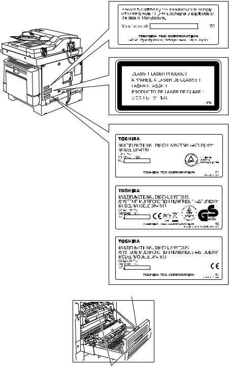
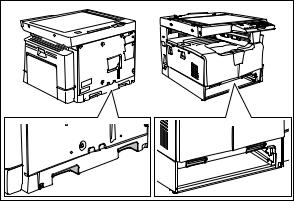
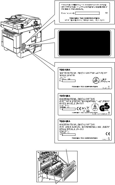
4)Cautionary Labels
—During servicing, be sure to check the rating plate and cautionary labels such as “Unplug the power cable during service”, “CAUTION. HOT”, “CAUTION. HIGH VOLTAGE”, “CAUTION. LASER BEAM”, etc. to see if there is any dirt on their surface and if they are properly stuck to the equipment.
Certification label (For UC)
Explanatory label
Identification label
For UC
For EU
For others
Warning for high-temperature areas (ventilation holes)
Warning for high-temperature areas (fuser unit)

5)Disposal of the Equipment, Supplies, Packing Materials, Used Batteries and IC-RAMs
—Regarding the recovery and disposal of the equipment, supplies, packing materials, used batteries and IC-RAMs including lithium batteries, follow the relevant local regulations or rules.
Caution:
Dispose of used batteries and IC-RAMs including lithium batteries according to this manual.
Attention:
Se débarrasser de batteries et IC-RAMs usés y compris les batteries en lithium selon ce manuel.
Vorsicht:
Entsorgung der gebrauchten Batterien und IC-RAMs (inclusive der Lithium-Batterie) nach diesem Handbuch.

ALLEGEMEINE SICHERHEITSMASSNAHMEN IN BEZUG AUF DIE WARTUNG FÜR e-STUDIO181/211
Die Installation und die Wartung sind von einem qualifizierten ServiceTechniker durchzuführen.
1)Transport/Installation
—Zum Transportieren/Installieren des Gerätes werden 2 Personen benötigt. Die Kassette zuerst herausnehmen und nur an den in der Abbildung gezeigten Stellen tragen.
Das Gerät ist sehr schwer und wiegt etwa 34 kg; deshalb muss bei der Handhabung des Geräts besonders aufgepasst werden.
—Beim Transportieren des Geräts nicht an den beweglichen Teilen oder Einheiten halten.
—Eine spezielle Steckdose mit Stromversorgung von AC 110 V / 13.2 A, 115 V oder 127 V / 12 A, 220-240 V / 8 A als Stromquelle verwenden.
—Das Gerät ist aus Sicherheitsgründen zu erden.
—Einen geeigneten Standort für die Installation wählen. Standorte mit zuviel Hitze, hoher Luftfeuchtigkeit, Staub, Vibrieren und direkter Sonneneinstrahlung sind zu vermeiden.
—Für ausreichende Belüftung sorgen, da das Gerät etwas Ozon abgibt.
—Um einen optimalen Kopierbetrieb zu gewährleisten, muss ein Abstand von mindestens 80 cm links, 80 cm rechts und 10 cm dahinter eingehalten werden.
—Das Gerät ist in der Nähe der Steckdose zu installieren; diese muss leicht zu erreichen sein.
—Nach der Installation muss das Netzkabel richtig hineingesteckt und befestigt werden, damit niemand darüber stolpern kann.
2)Allgemeine Sicherheitsmassnahmen in bezug auf die Wartung
—Während der Wartung das Gerät ausschalten und das Netzkabel herausziehen (ausser Wartung, die bei einem eingeschalteten Gerät, durchgeführt werden muss).
—Das Netzkabel herausziehen und den Bereich um die Steckerpole und die Steckdose die Umgebung in der Nähe von den Steckerzacken und der Steckdose wenigstens einmal im Jahr reinigen. Wenn Staub sich in dieser Gegend ansammelt, kann dies ein Feuer verursachen.
—Wenn die Teile auseinandergenommen werden, wenn nicht anders in diesem Handbuch usw erklärt, ist das Zusammenbauen in umgekehrter Reihenfolge durchzuführen. Aufpassen, dass kleine Teile wie Schrauben, Dichtungsringe, Bolzen, E-Ringe, Stern-Dichtungsringe, Kabelbäume nicht an den verkehrten Stellen eingebaut werden.
—Grundsätzlich darf das Gerät mit enfernten oder auseinandergenommenen Teilen nicht in Betrieb genommen werden.
—Das PC-Board muss in einer Anti-elektrostatischen Hülle gelagert werden. Nur Mit einer Manschette bei Betätigung eines Armbandes anfassen, sonst könnte es sein, dass die integrierten Schaltkreise durch statische Elektrizität beschädigt werden.
Vorsicht: Vor Benutzung der Manschette der Betätigung des Armbandes, das Netzkabel des Gerätes herausziehen und prüfen, dass es in der Nähe keine geladenen Gegenstände, die nicht isoliert sind, gibt.
—Setzen Sie sich während der Wartungsarbeiten nicht dem Laserstrahl aus. Dieses Gerät ist mit einer Laserdiode ausgestattet. Es ist unbedingt zu vermeiden, direkt in den Laserstrahl zu blicken. Keine reflektierenden Teile oder Werkzeuge, wie z. B. Schraubendreher, in den Pfad des Laserstrahls halten. Vor den Wartungsarbeiten sämtliche reflektierenden Metallgegenstände, wie Uhren, Ringe usw., entfernen.
—Auf keinen Fall Hochtemperaturbereiche, wie die Belichtungslampe, die Fixiereinheit, die Heizquelle und die umliegenden Bereiche, berühren.
—Auf keinen Fall Hochspannungsbereiche, wie die Ladeeinheiten, die Entwicklereinheit, den Hochspannungstransformator, und das Netzgerät, berühren. Insbesondere sollten die Platinen dieser Komponenten nicht berührt werden, da die Kondensatoren usw. auch nach dem Ausschalten des Geräts noch elektrisch geladen sein können.
—Vor dem Berühren potenziell gefährlicher Bereiche (z. B. drehbare oder betriebsrelevante Bereiche, wie Zahnräder, Riemen, Riemenscheiben, Lüfter und die Laseraustrittsöffnung der optischen Lasereinheit) sicherstellen, dass das Gerät sich nicht bedienen lässt.
—Beim Entfernen von Abdeckungen vorsichtig vorgehen, da sich darunter scharfkantige Komponenten befinden können.
—Bei Wartungsarbeiten am eingeschalteten Gerät dürfen keine unter Strom stehenden, drehbaren oder betriebsrelevanten Bereiche berührt werden. Nicht direkt in den Laserstrahl blicken.
—Ausschließlich vorgesehene Werkzeuge und Hilfsmittel verwenden.
—Empfohlene oder gleichwertige Messgeräte verwenden.
—Nach Abschluss der Wartungsarbeiten das Gerät in den ursprünglichen Zustand zurück versetzen und den einwandfreien Betrieb überprüfen.
3)Sicherheitsrelevante Wartungsteile
—Der Leistungsschutzschalter, der Türschalter, die Sicherung, der Thermostat, die Thermosicherung, der Thermistor, die IC-RAMs einschließlich der Lithiumakkus usw. sind besonders sicherheitsrelevant. Sie müssen unbedingt korrekt gehandhabt und installiert werden. Wenn diese Teile kurzgeschlossen und funktionsunfähig werden, kann dies zu schwerwiegenden Schäden, wie einem Abbrand, führen. Kurzschlüsse sind zu vermeiden, und es sind ausschließlich Teile zu verwenden, die von der Toshiba TEC Corporation empfohlen sind.
4)Warnetiketten
—Im Rahmen der Wartung unbedingt das Leistungsschild und die Etiketten mit Warnhinweisen überprüfen [z. B. „Unplug the power cable during service“ („Netzkabel vor Beginn der Wartungsarbeiten abziehen“), „CAUTION. HOT“ („VORSICHT, HEISS“), „CAUTION. HIGH VOLTAGE“ („VORSICHT, HOCHSPANNUNG“), „CAUTION. LASER BEAM“ („VORSICHT, LASER“) usw.], um sicherzustellen, dass sie nicht verschmutzt sind und korrekt am Gerät angebracht sind.
Certification label (For UC)
Explanatory label
Identification label
For UC
For EU
For others
Warning for high-temperature areas (ventilation holes)
Warning for high-temperature areas (fuser unit)

5)Entsorgung des Geräts, der Verbrauchsund Verpackungsmaterialien, alter Akkus und IC-RAMs
—In Bezug auf die Entsorgung und Wiederverwertung des Geräts, der Verbrauchsund Verpackungsmaterialien, alter Akkus und IC-RAMs, einschließlich Lithiumakkus, sind die einschlägigen nationalen oder regionalen Vorschriften zu befolgen.
Caution:
Dispose of used batteries and IC-RAMs including lithium batteries according to this manual.
Attention:
Se débarrasser de batteries et IC-RAMs usés y compris les batteries en lithium selon ce manuel.
Vorsicht:
Entsorgung der gebrauchten Batterien und IC-RAMs (inclusive der Lithium-Batterie) nach diesem Handbuch.
![]()
•Laseremissionseinheit
Diese Einheit besteht aus der Laserdiode, dem Fokussierungsobjektiv, der Blende und dem Zylinderobjektiv.
—Laserdiode
Diese Laserdiode zeichnet sich durch eine geringe Regeldifferenz, eine kleine Laservariation und einen niedrigen Schwellenstrom aus.
Die Blende der Laseremissionseinheit ist unter dem Fokussierobjektiv angeordnet, um die Form der Laserstrahlen in der primären und sekundären Scanrichtung festzulegen.
Die Laserdiode gibt Laserstrahlen als Reaktion auf die Signale der Laseremissionssteuerung (ein/ aus) von der Lasertreiber-PC-Platine (LDR) aus. Die durch das Fokussierobjektiv geführten Laserstrahlen werden auf die Trommeloberfläche fokussiert.
—Vorsichtsmaßnahmen im Zusammenhang mit Lasern
Dieses Gerät enthält eine Laserdiode, die einen unsichtbaren Laserstrahl emittiert.
Da man diesen Laserstrahl nicht sehen kann, ist bei der Handhabung der Komponenten der optischen Lasereinheit, bei der Durchführung von Arbeiten und bei der Justierung des Laserstrahls äußerste Vorsicht geboten. Arbeiten dürfen niemals anhand anderer als den vorgeschriebenen Anleitungen durchgeführt werden; andernfalls kann es zu einer Schädigung Exposition durch Laserstrahlung kommen.
Die Lasereinheit ist vollständig mit einer Schutzabdeckung versiegelt. Solange ausschließlich die Arbeitsschritte der vorgeschriebenen Anleitungen durchgeführt werden, tritt der Laserstrahl nicht aus, und es besteht keine Gefahr, der Laserstrahlung ausgesetzt zu werden.
Das folgende Laser-Warnetikett ist an der Abdeckung vorne rechts angebracht.
•Warnhinweise:
—Setzen Sie sich während der Wartungsarbeiten nicht dem Laserstrahl aus.
Dieses Gerät ist mit einer Laserdiode ausgestattet. Es ist unbedingt zu vermeiden, direkt in den Laserstrahl zu blicken. Keine reflektierenden Teile oder Werkzeuge, wie z. B. Schraubendreher, in den Pfad des Laserstrahls halten. Vor den Wartungsarbeiten sämtliche reflektierenden Metallgegenstände, wie Uhren, Ringe usw., entfernen.
—Bei Wartungsarbeiten am eingeschalteten Gerät dürfen keine unter Strom stehenden, drehbaren oder betriebsrelevanten Bereiche berührt werden. Nicht direkt in den Laserstrahl blicken.
—Im Rahmen der Wartung unbedingt das Leistungsschild und die Etiketten mit Warnhinweisen überprüfen [z. B. „Unplug the power cable during service“ („Netzkabel vor Beginn der Wartungsarbeiten abziehen“), „CAUTION. HOT“ („VORSICHT, HEISS“), „CAUTION. HIGH VOLTAGE“ („VORSICHT, HOCHSPANNUNG“), „CAUTION. LASER BEAM“ („VORSICHT, LASER“) usw.], um sicherzustellen, dass sie nicht verschmutzt sind und korrekt am Gerät angebracht sind.
CONTENTS
|
1. SPECIFICATIONS / ACCESSORIES / OPTIONS / SUPPLIES …………………………….. |
1-1 |
|
|
1.1 |
Specifications……………………………………………………………………………………………………….. |
1-1 |
|
1.2 |
Accessories …………………………………………………………………………………………………………. |
1-4 |
|
1.3 |
Options ……………………………………………………………………………………………………………….. |
1-5 |
|
1.4 |
Supplies………………………………………………………………………………………………………………. |
1-6 |
|
1.5 |
System List ………………………………………………………………………………………………………….. |
1-7 |
|
2. OUTLINE OF THE MACHINE …………………………………………………………………………… |
2-1 |
||
|
2.1 |
Sectional View ……………………………………………………………………………………………………… |
2-1 |
|
|
2.2 |
Electric Parts Layout……………………………………………………………………………………………… |
2-4 |
|
|
2.2.1 |
Scanner, control panel ………………………………………………………………………………… |
2-4 |
|
|
2.2.2 Power supply section, switches…………………………………………………………………….. |
2-5 |
||
|
2.2.3 Laser optical unit, fuser unit, toner cartridge section………………………………………… |
2-6 |
||
|
2.2.4 |
Developer unit section…………………………………………………………………………………. |
2-7 |
|
|
2.2.5 |
Driving section……………………………………………………………………………………………. |
2-8 |
|
|
2.2.6 |
Drawer section …………………………………………………………………………………………… |
2-9 |
|
|
2.2.7 |
Bypass unit………………………………………………………………………………………………. |
2-10 |
|
|
2.3 Symbols and Functions of Various Components……………………………………………………… |
2-11 |
||
|
2.4 |
General Description…………………………………………………………………………………………….. |
2-15 |
|
|
2.4.1 |
System block diagram ……………………………………………………………………………….. |
2-15 |
|
|
2.4.2 |
Construction of boards ………………………………………………………………………………. |
2-16 |
|
|
2.5 Disassembly and Replacement of Covers………………………………………………………………. |
2-18 |
||
|
2.5.1 |
Front cover ………………………………………………………………………………………………. |
2-18 |
|
|
2.5.2 |
Inner tray …………………………………………………………………………………………………. |
2-18 |
|
|
2.5.3 |
Left cover…………………………………………………………………………………………………. |
2-18 |
|
|
2.5.4 |
Tray rear cover …………………………………………………………………………………………. |
2-19 |
|
|
2.5.5 |
Front right cover ……………………………………………………………………………………….. |
2-19 |
|
|
2.5.6 |
Front upper cover ……………………………………………………………………………………… |
2-19 |
|
|
2.5.7 |
ADU cover ……………………………………………………………………………………………….. |
2-20 |
|
|
2.5.8 |
Right front cover ……………………………………………………………………………………….. |
2-20 |
|
|
2.5.9 |
Right rear cover………………………………………………………………………………………… |
2-21 |
|
|
2.5.10 Rear cover……………………………………………………………………………………………….. |
2-21 |
||
|
2.6 Disassembly and Replacement of PC boards …………………………………………………………. |
2-22 |
||
|
2.6.1 |
MAIN board (MAIN)…………………………………………………………………………………… |
2-22 |
|
|
2.6.2 |
SRAM board (SRAM) ………………………………………………………………………………… |
2-23 |
|
|
2.6.3 Fuse PC board (FUS)………………………………………………………………………………… |
2-24 |
||
|
2.6.4 Switching regulator unit (PS)………………………………………………………………………. |
2-24 |
||
|
2.6.5 Switching regulator cooling fan (M6) ……………………………………………………………. |
2-27 |
||
|
2.7 Removal and Installation of Options………………………………………………………………………. |
2-28 |
||
|
2.7.1 MR-2020 (Automatic Document Feeder (ADF))/ |
|||
|
MR-3023 (Reversing Automatic Document Feeder (RADF)) …………………………… |
2-28 |
||
|
2.7.2 MY-1027 (Paper Feed Unit (PFU))………………………………………………………………. |
2-30 |
|
3. COPY PROCESS ……………………………………………………………………………………………. |
3-1 |
|
|
3.1 |
General Description of Copying Process………………………………………………………………….. |
3-1 |
|
3.2 |
Details of Copying Process…………………………………………………………………………………….. |
3-2 |
|
3.3 |
Comparison with e-STUDIO165/205 ……………………………………………………………………… |
3-13 |
|
4. GENERAL OPERATION………………………………………………………………………………….. |
4-1 |
|
|
4.1 |
Overview of Operation …………………………………………………………………………………………… |
4-1 |
|
4.2 |
Description of Operation………………………………………………………………………………………… |
4-2 |
|
4.2.1 Warming-up……………………………………………………………………………………………….. |
4-2 |
|
|
4.2.2 Ready state (ready for copying) ……………………………………………………………………. |
4-2 |
|
|
© 2009 TOSHIBA TEC CORPORATION All rights reserved |
e-STUDIO181/211 |
|
|
CONTENTS |
1
|
4.2.3 |
Drawer feed copying …………………………………………………………………………………… |
4-3 |
||
|
4.2.4 |
Bypass feed copying …………………………………………………………………………………… |
4-4 |
||
|
4.2.5 |
Interruption copying…………………………………………………………………………………….. |
4-4 |
||
|
4.3 |
Detection of Abnormality………………………………………………………………………………………… |
4-5 |
||
|
4.3.1 |
Types of abnormality …………………………………………………………………………………… |
4-5 |
||
|
4.3.2 |
Description of abnormality……………………………………………………………………………. |
4-6 |
||
|
5. |
CONTROL PANEL………………………………………………………………………………………….. |
5-1 |
||
|
5.1 |
Control Panel and LED Display ……………………………………………………………………………… |
5-1 |
||
|
5.2 |
Items Displayed on Control Panel …………………………………………………………………………… |
5-2 |
||
|
5.3 |
Relation between Equipment State and Operation…………………………………………………….. |
5-4 |
||
|
5.4 |
Operation…………………………………………………………………………………………………………….. |
5-5 |
||
|
5.4.1 |
Block diagram…………………………………………………………………………………………….. |
5-5 |
||
|
5.4.2 |
LED display circuit………………………………………………………………………………………. |
5-5 |
||
|
5.5 |
Disassembly and Replacement ………………………………………………………………………………. |
5-6 |
||
|
5.5.1 |
Control panel unit ……………………………………………………………………………………….. |
5-6 |
||
|
5.5.2 Control panel PC board (LPNL) ……………………………………………………………………. |
5-6 |
|||
|
6. |
SCANNER ……………………………………………………………………………………………………… |
6-1 |
||
|
6.1 |
General Description………………………………………………………………………………………………. |
6-1 |
||
|
6.2 |
Construction…………………………………………………………………………………………………………. |
6-2 |
||
|
6.3 |
Functions …………………………………………………………………………………………………………….. |
6-3 |
||
|
6.4 |
Description of Operation………………………………………………………………………………………… |
6-5 |
||
|
6.4.1 |
Scanning operation …………………………………………………………………………………….. |
6-5 |
||
|
6.4.2 Scan motor drive circuit……………………………………………………………………………….. |
6-6 |
|||
|
6.5 |
Contact Image Sensor Unit Control Circuit……………………………………………………………….. |
6-8 |
||
|
6.5.1 Exposure LED control circuit ………………………………………………………………………… |
6-8 |
|||
|
6.5.2 |
CCD control circuit ……………………………………………………………………………………… |
6-9 |
||
|
6.6 |
Disassembly and Replacement …………………………………………………………………………….. |
6-10 |
||
|
6.6.1 |
Original glass……………………………………………………………………………………………. |
6-10 |
||
|
6.6.2 |
Scanner top cover …………………………………………………………………………………….. |
6-11 |
||
|
6.6.3 |
Scan motor (M1)……………………………………………………………………………………….. |
6-11 |
||
|
6.6.4 CIS home position sensor (S1) …………………………………………………………………… |
6-13 |
|||
|
6.6.5 |
Platen sensor (S2)…………………………………………………………………………………….. |
6-13 |
||
|
6.6.6 |
CIS unit (CIS) …………………………………………………………………………………………… |
6-14 |
||
|
6.6.7 |
CIS case………………………………………………………………………………………………….. |
6-16 |
||
|
6.6.8 CIS unit drive belt-1 ………………………………………………………………………………….. |
6-17 |
|||
|
6.6.9 CIS unit drive belt-2…………………………………………………………………………………… |
6-18 |
|||
|
7. |
LASER OPTICAL UNIT …………………………………………………………………………………… |
7-1 |
||
|
7.1 |
General Description………………………………………………………………………………………………. |
7-1 |
||
|
7.2 |
Structure ……………………………………………………………………………………………………………… |
7-2 |
||
|
7.3 |
Laser Diode Control Circuit…………………………………………………………………………………….. |
7-5 |
||
|
7.4 |
Polygonal Motor Control Circuit ………………………………………………………………………………. |
7-6 |
||
|
7.5 |
Disassembly and Replacement ………………………………………………………………………………. |
7-7 |
||
|
7.5.1 |
Laser optical unit ………………………………………………………………………………………… |
7-7 |
||
|
8. |
DRIVE UNIT …………………………………………………………………………………………………… |
8-1 |
||
|
8.1 |
General Description………………………………………………………………………………………………. |
8-1 |
||
|
8.2 |
Configuration ……………………………………………………………………………………………………….. |
8-2 |
||
|
8.3 |
Functions ……………………………………………………………………………………………………………. |
8-3 |
||
|
8.4 |
Main Motor Control Circuit……………………………………………………………………………………… |
8-4 |
||
|
8.5 |
Disassembly and Replacement ………………………………………………………………………………. |
8-6 |
||
|
8.5.1 |
Main motor (M3) …………………………………………………………………………………………. |
8-6 |
||
|
8.5.2 |
Toner motor (M2) ……………………………………………………………………………………….. |
8-6 |
||
|
8.5.3 Main motor drive unit…………………………………………………………………………………… |
8-7 |
|||
|
e-STUDIO181/211 |
© 2009 TOSHIBA TEC CORPORATION All rights reserved |
|||
|
CONTENTS |
2
|
9. PAPER FEEDING SYSTEM……………………………………………………………………………… |
9-1 |
||
|
9.1 |
General Description………………………………………………………………………………………………. |
9-1 |
|
|
9.2 |
Configuration ……………………………………………………………………………………………………….. |
9-2 |
|
|
9.3 |
Functions …………………………………………………………………………………………………………….. |
9-3 |
|
|
9.4 |
Operation…………………………………………………………………………………………………………….. |
9-5 |
|
|
9.4.1 |
Drawer………………………………………………………………………………………………………. |
9-5 |
|
|
9.4.2 |
Bypass tray………………………………………………………………………………………………… |
9-7 |
|
|
9.4.3 |
General operation……………………………………………………………………………………….. |
9-9 |
|
|
9.5 |
Disassembly and Replacement …………………………………………………………………………….. |
9-10 |
|
|
9.5.1 |
Bypass unit………………………………………………………………………………………………. |
9-10 |
|
|
9.5.2 |
Bypass tray………………………………………………………………………………………………. |
9-11 |
|
|
9.5.3 |
Bypass separation pad ……………………………………………………………………………… |
9-11 |
|
|
9.5.4 |
Bypass roller unit………………………………………………………………………………………. |
9-12 |
|
|
9.5.5 |
Bypass pickup roller …………………………………………………………………………………. |
9-14 |
|
|
9.5.6 |
Bypass feed roller …………………………………………………………………………………….. |
9-14 |
|
|
9.5.7 |
Bypass paper sensor (S8)………………………………………………………………………….. |
9-14 |
|
|
9.5.8 |
Bypass pickup solenoid (SOL2) ………………………………………………………………….. |
9-15 |
|
|
9.5.9 |
Bypass pickup clutch / Bypass feed clutch……………………………………………………. |
9-16 |
|
|
9.5.10 |
Damp heater unit (DH3) / Dummy plate ……………………………………………………….. |
9-18 |
|
|
9.5.11 |
Paper empty sensor (S7) …………………………………………………………………………… |
9-18 |
|
|
9.5.12 |
Pickup roller …………………………………………………………………………………………….. |
9-19 |
|
|
9.5.13 |
Registration clutch (CLT1)………………………………………………………………………….. |
9-20 |
|
|
9.5.14 |
Pickup solenoid (SOL1)……………………………………………………………………………… |
9-20 |
|
|
9.5.15 |
Drawer pickup clutch …………………………………………………………………………………. |
9-21 |
|
|
9.5.16 |
Registration roller (rubber) …………………………………………………………………………. |
9-22 |
|
|
9.5.17 |
Registration roller (metal) …………………………………………………………………………… |
9-23 |
|
|
9.5.18 |
Feed gear unit ………………………………………………………………………………………….. |
9-24 |
|
|
9.5.19 |
Drawer detection switch (SW5) …………………………………………………………………… |
9-24 |
|
|
9.5.20 |
Registration sensor (S4)…………………………………………………………………………….. |
9-25 |
|
10. DRUM RELATED SECTION …………………………………………………………………………… |
10-1 |
|
|
10.1 |
General Description…………………………………………………………………………………………….. |
10-1 |
|
10.2 |
Configuration ……………………………………………………………………………………………………… |
10-2 |
|
10.3 |
Functions …………………………………………………………………………………………………………… |
10-3 |
|
10.4 |
High-Voltage Output Control Circuit ………………………………………………………………………. |
10-5 |
|
10.4.1 General description …………………………………………………………………………………… |
10-5 |
|
|
10.4.2 Description of Operation…………………………………………………………………………….. |
10-6 |
|
|
10.5 |
Drum Temperature Detection Circuit ……………………………………………………………………… |
10-7 |
|
10.5.1 General description …………………………………………………………………………………… |
10-7 |
|
|
10.5.2 Circuit configuration…………………………………………………………………………………… |
10-7 |
|
|
10.6 |
Temperature/Humidity Detection Circuit…………………………………………………………………. |
10-8 |
|
10.6.1 General Description…………………………………………………………………………………… |
10-8 |
|
|
10.6.2 Circuit configuration…………………………………………………………………………………… |
10-8 |
|
|
10.7 |
Disassembly and Replacement …………………………………………………………………………….. |
10-9 |
|
10.7.1 Process unit……………………………………………………………………………………………… |
10-9 |
|
|
10.7.2 Drum cleaner unit ……………………………………………………………………………………. |
10-10 |
|
|
10.7.3 Discharge LED (ERS) ……………………………………………………………………………… |
10-11 |
|
|
10.7.4 Main charger ………………………………………………………………………………………….. |
10-12 |
|
|
10.7.5 Main charger grid …………………………………………………………………………………… |
10-12 |
|
|
10.7.6 Main charger cleaner……………………………………………………………………………….. |
10-13 |
|
|
10.7.7 Needle electrode ……………………………………………………………………………………. |
10-13 |
|
|
10.7.8 Drum …………………………………………………………………………………………………….. |
10-14 |
|
|
10.7.9 Drum cleaning blade ………………………………………………………………………………. |
10-14 |
|
|
10.7.10Drum separation finger …………………………………………………………………………… |
10-14 |
|
|
10.7.11Recovery blade ……………………………………………………………………………………… |
10-15 |
|
|
© 2009 TOSHIBA TEC CORPORATION All rights reserved |
e-STUDIO181/211 |
|
|
CONTENTS |
3
|
10.7.12Transfer/Separation charger…………………………………………………………………….. |
10-15 |
||
|
10.7.13Charger wire …………………………………………………………………………………………. |
10-16 |
||
|
10.7.14Transfer unit…………………………………………………………………………………………… |
10-17 |
||
|
10.7.15Ozone filter …………………………………………………………………………………………… |
10-18 |
||
|
10.7.16Exhaust fan (M5) ……………………………………………………………………………………. |
10-19 |
||
|
10.7.17Temperature/humidity sensor (S3) ……………………………………………………………. |
10-20 |
||
|
10.7.18Toner cartridge interface PC board (CTIF) …………………………………………………. |
10-21 |
||
|
11. DEVELOPMENT SYSTEM……………………………………………………………………………… |
11-1 |
||
|
11.1 |
General Description…………………………………………………………………………………………….. |
11-1 |
|
|
11.2 |
Construction……………………………………………………………………………………………………….. |
11-2 |
|
|
11.3 |
Functions …………………………………………………………………………………………………………… |
11-3 |
|
|
11.3.1 Function of each unit …………………………………………………………………………………. |
11-3 |
||
|
11.3.2 Functions of the toner cartridge PC board (CTRG) ………………………………………… |
11-4 |
||
|
11.3.3 Recovered toner supply mechanism ……………………………………………………………. |
11-6 |
||
|
11.4 |
Toner Motor Control Circuit ………………………………………………………………………………….. |
11-7 |
|
|
11.5 |
Auto-Toner Circuit……………………………………………………………………………………………….. |
11-8 |
|
|
11.5.1 General description …………………………………………………………………………………… |
11-8 |
||
|
11.5.2 Function of auto-toner sensor …………………………………………………………………….. |
11-9 |
||
|
11.6 |
Disassembly and Replacement …………………………………………………………………………… |
11-11 |
|
|
11.6.1 Developer unit ………………………………………………………………………………………… |
11-11 |
||
|
11.6.2 Developer material …………………………………………………………………………………. |
11-12 |
||
|
11.6.3 Filling developer unit with developer material………………………………………………. |
11-13 |
||
|
11.6.4 Auto-toner sensor (S6) …………………………………………………………………………….. |
11-14 |
||
|
11.6.5 Drum thermistor (THMS4) ………………………………………………………………………… |
11-14 |
||
|
11.6.6 Guide roller / Developer sleeve …………………………………………………………………. |
11-14 |
||
|
11.6.7 Mixer……………………………………………………………………………………………………… |
11-18 |
||
|
11.6.8 Replacement of Oil Seal…………………………………………………………………………… |
11-20 |
||
|
12. FUSER / EXIT UNIT ………………………………………………………………………………………. |
12-1 |
||
|
12.1 |
General Description…………………………………………………………………………………………….. |
12-1 |
|
|
12.2 |
Configurations…………………………………………………………………………………………………….. |
12-2 |
|
|
12.3 |
Functions …………………………………………………………………………………………………………… |
12-3 |
|
|
12.4 |
Operation…………………………………………………………………………………………………………… |
12-4 |
|
|
12.5 |
Fuser Unit Control Circuit …………………………………………………………………………………….. |
12-5 |
|
|
12.5.1 Configuration ……………………………………………………………………………………………. |
12-5 |
||
|
12.5.2 Temperature detection section……………………………………………………………………. |
12-6 |
||
|
12.6 |
Disassembly and Replacement …………………………………………………………………………… |
12-11 |
|
|
12.6.1 Fuser/Paper exit unit ……………………………………………………………………………….. |
12-13 |
||
|
12.6.2 Pressure roller unit / Fuser roller unit ………………………………………………………… |
12-13 |
||
|
12.6.3 Exit roller ……………………………………………………………………………………………….. |
12-14 |
||
|
12.6.4 Exit sensor (S5) ……………………………………………………………………………………… |
12-15 |
||
|
12.6.5 Separation finger …………………………………………………………………………………… |
12-17 |
||
|
12.6.6 Center heater lamp / Side heater lamp (LAMP1/LAMP2)………………………………. |
12-17 |
||
|
12.6.7 Fuser roller ……………………………………………………………………………………………. |
12-18 |
||
|
12.6.8 Pressure roller ……………………………………………………………………………………….. |
12-19 |
||
|
12.6.9 Center thermistor / Side thermistor / Edge thermistor (THMS1/THMS2/THMS3) 12-20 |
|||
|
12.6.10Fuser thermostat (THMO1)………………………………………………………………………. |
12-21 |
||
|
13. POWER SUPPLY UNIT …………………………………………………………………………………. |
13-1 |
||
|
13.1 |
Construction……………………………………………………………………………………………………….. |
13-1 |
|
|
13.2 |
Operation of DC Output Circuit……………………………………………………………………………… |
13-2 |
|
|
13.3 |
Output Channel ………………………………………………………………………………………………….. |
13-3 |
|
|
13.4 |
Fuse………………………………………………………………………………………………………………….. |
13-4 |
|
|
13.5 |
Configuration of Power Supply Unit……………………………………………………………………….. |
13-5 |
|
|
13.6 |
AC Wire Harness………………………………………………………………………………………………… |
13-6 |
|
|
e-STUDIO181/211 |
© 2009 TOSHIBA TEC CORPORATION All rights reserved |
||
|
CONTENTS |
4
|
14. EXTERNAL COUNTERS ……………………………………………………………………………….. |
14-1 |
|
|
14.1 |
Outline ………………………………………………………………………………………………………………. |
14-1 |
|
14.2 |
Signal………………………………………………………………………………………………………………… |
14-1 |
|
14.2.1 Pin Layout ……………………………………………………………………………………………….. |
14-1 |
|
|
14.2.2 Details of the signals …………………………………………………………………………………. |
14-2 |
|
|
14.3 |
Notices………………………………………………………………………………………………………………. |
14-3 |
|
14.3.1 Setting code …………………………………………………………………………………………….. |
14-3 |
|
|
14.3.2 Setting value change and restrictions when using the totalizer (DocuLyzerNW) … |
14-3 |
|
|
14.3.3 Setting value change and restrictions when using the coin controller……………….. |
14-3 |
|
|
14.3.4 Simultaneous Installation of External Counters……………………………………………… |
14-3 |
|
|
15. PC BOARDS ………………………………………………………………………………………………… |
15-1 |
|
© 2009 TOSHIBA TEC CORPORATION All rights reserved |
e-STUDIO181/211 |
|
CONTENTS |
5
|
e-STUDIO181/211 |
© 2009 TOSHIBA TEC CORPORATION All rights reserved |
|
CONTENTS |
6

1.SPECIFICATIONS / ACCESSORIES / OPTIONS / SUPPLIES
Values in [ ] are for e- STUDIO211 in case that the specification is different among e-STUDIO181 and e-STUDIO211.
|
Copy process |
Indirect electrophotographic process (dry) |
|||||
|
Type |
Desktop type |
|||||
|
Original table |
Fixed type (the left rear corner used as guide to place originals) |
|||||
|
Accepted originals |
Sheet, book and 3-dimensional object. The automatic document feeder |
|||||
|
(ADF) only accepts paper which are not pasted or stapled. (Single-sided |
||||||
|
originals: 50 to 127 g/m2/13 to 34 lb. Bond) Carbon paper are not acceptable |
||||||
|
either. |
||||||
|
Maximum size: A3/LD |
||||||
|
Copy speed (Copies/min.) |
||||||
|
e-STUDIO181 |
||||||
|
Paper size |
Drawer |
Bypass feed |
PFU |
|||
|
Size specified |
Size not specified |
|||||
|
A4, B5, LT |
18 |
16 |
11 |
16 |
||
|
A5-R, ST-R |
— |
16 |
11 |
— |
||
|
A4-R, B5-R, LT-R |
15.5 |
15.5 |
11 |
15.5 |
||
|
B4, LG, FOLIO, COMPUTER |
13 |
13 |
11 |
13 |
||
|
A3, LD |
11 |
11 |
11 |
11 |
||
|
e-STUDIO211 |
||||||
|
Paper size |
Drawer |
Bypass feed |
PFU |
|||
|
Size specified |
Size not specified |
|||||
|
A4, B5, LT |
21 |
20 |
11 |
20 |
||
|
A5-R, ST-R |
— |
20 |
11 |
— |
||
|
A4-R, B5-R, LT-R |
15.5 |
15.5 |
11 |
15.5 |
||
|
B4, LG, FOLIO, COMPUTER |
13 |
13 |
11 |
13 |
||
|
A3, LD |
11 |
11 |
11 |
11 |
*“–” means “Not acceptable”.
*The copy speed in the above table are available when originals are manually placed for single side, multiple copying.
*When the ADF is used, the copy speed of 16[20] sheets per minute is only available under the
|
following conditions: |
||
|
• |
Original/Mode: |
Single side original/A4/LT size. APS/automatic density are not selected. |
|
• |
Number of sheets: |
16[20] or more. |
•Reproduction ratio: 100%
|
© 2009 TOSHIBA TEC CORPORATION All rights reserved |
e-STUDIO181/211 |
SPECIFICATIONS / ACCESSORIES / OPTIONS / SUPPLIES |
1 — 1
Copy speed for thick paper (Copies/min.) e-STUDIO181/211
Thick 1 (81 g/m2 to 105 g/m2, 21.3 lb. Bond to 28 lb. Bond): Bypass feed on a sheet by sheet basis only Thick 2 (106 g/m2 to 163 g/m2, 28 lb. Bond to 90 lb. Index): Bypass feed on a sheet by sheet basis only
Copy paper
|
Drawer |
PFU |
Bypass copy |
Remarks |
|||
|
Size |
A3, A4, A4-R, |
B4, B5, |
A3 to A5-R, LD to ST-R, FOLIO, |
|||
|
B5-R, LD, LG, LT, LT-R, |
COMPUTER, 13″LG, 8.5″ x 8.5″, 8K, |
|||||
|
FOLIO, COMPUTER, |
16K, 16K-R |
|||||
|
13″LG, 8.5″ x 8.5″, 8K, |
(Non-standard or user-specified sizes |
|||||
|
16K, 16K-R |
can be set.) |
|||||
|
Weight |
64 to 80 g/m2 |
50 to 163 g/m2(Single paper feeding) |
||||
|
64 to 80 g/m2(Continuous feeding) |
||||||
|
Special |
– |
Tracing paper, labels, OHP film |
These special papers |
|||
|
paper |
(thickness: 80 µm or thicker), |
recommended by Toshiba |
||||
|
Tec |
||||||
|
First copy time ………………… |
Approx. 7.6 sec. (A4, 100%, original placed manually) |
|||||
|
Approx. 7.7 sec. (LT, 100%, original placed manually) |
||||||
|
Warming-up time……………… |
Approx. 25 sec. (temperature: 20°C) |
|||||
|
Multiple copying ………………. |
Up to 999 copies; Key in set numbers |
|||||
|
Reproduction ratio …………… |
Actual ratio: 100±0.5% |
|||||
|
Zooming: 25 to 200% in increments of 1% |
||||||
|
Resolution/Gradation |
……….. |
Scanning: 600 dpi x 600 dpi |
||||
|
Printing: Equivalent to 2400 dpi x 600 dpi |
||||||
|
Gradation: 256 steps |
||||||
|
Eliminated portion ……………. |
Leading edges: 3.0±2.0 mm, Side/trailing edges: 2.0±2.0 mm (copy) |
|||||
|
Leading / trailing edges: 5.0±2.0 mm, Side edges: 5.0±2.0 mm (print) |
||||||
|
Paper feeding ……………………. |
Standard drawer: |
|||||
|
1 drawer (stack height 28 mm, equivalent to 250 sheets; 64 to |
||||||
|
80 g/m2 (17 to 22 lb. Bond)) |
||||||
|
Bypass feeding: |
||||||
|
Stack height 11.8 mm: equivalent to 100 sheets; 64 to 80 g/m2 |
||||||
|
(17 to 22 lb. Bond) |
||||||
|
Paper Feed Unit (PFU): |
||||||
|
Option (One drawer: stack height 28 mm, equivalent to 250 |
||||||
|
sheets; 64 to 80 g/m2 (17 to 22 lb. Bond)) |
||||||
|
Capacity of originals in the automatic document feeder (Option) |
||||||
|
………………………………………….. |
A3 to A5-R, LD to ST-R: |
|||||
|
100 sheets / 80 g/m2 (Stack height 16 mm or less) |
||||||
|
Toner supply ……………………… |
Automatic toner density detection/supply |
|||||
|
Toner cartridge replacing method (There is a recovered toner supply |
||||||
|
mechanism.) |
||||||
|
Density control…………………… |
Automatic density mode and manual density mode selectable in 7 |
|||||
|
steps |
||||||
|
e-STUDIO181/211 |
© 2009 TOSHIBA TEC CORPORATION All rights reserved |
SPECIFICATIONS / ACCESSORIES / OPTIONS / SUPPLIES
1 — 2
![]()
|
Weight……………………………. |
Approx. 31.8 kg ( 70.11 lb.) (for NAD and others) |
|
|
Approx. 32.9 kg ( 72.53 lb.) (for MJD and CND) |
||
|
Approx. 34.2 kg ( 75.40 lb.) (for AUD) |
||
|
Power requirements…………. |
AC 110 V / 13.2 A, 115 V or 127 V / 12 A |
1 |
|
220-240 V or 240 V / 8 A (50/60 Hz) |
*The acceptable value of each voltage is ±10%.
|
Power consumption …………. |
1.5 kW or less (100 V series) |
1.6kW or less (200 V series)
*The electric power is supplied to the ADF and PFU through the equipment.
Total counter …………………… Electronical counter
Dimensions of the equipment
………………………………………….. W 600 x D 643 x H 462.5 (mm): See the figure below
D
H
W
Fig. 1-1
|
© 2009 TOSHIBA TEC CORPORATION All rights reserved |
e-STUDIO181/211 |
|
SPECIFICATIONS / ACCESSORIES / OPTIONS / SUPPLIES |
1 — 3
|
1.2 |
Accessories |
|
|
Unpacking/setup instruction |
1 set |
|
|
Operator’s manual |
1 pc. |
|
|
Operator’s manual pocket |
1 pc. (for NAD) |
|
|
Power cable |
1 pc. |
|
|
CD-ROM |
2 pcs. |
|
|
Rubber cap |
6 pcs. (for MJD, ASD, ASU and SAD) |
|
|
2 pcs. (for NAD, CND, AUD, TWD, KRD and ARD) |
||
|
Transfer charger wire cleaner |
1 pc. |
|
|
(installed inside of the transfer cover) |
||
|
Drum (installed inside of the equipment) |
1 pc. |
|
|
Developer material |
1 pc. |
|
|
Nozzle |
1 pc. (for NAD) |
|
|
Toner cartridge |
1 pc. |
|
|
Warranty sheet |
1 pc. (for NAD and CND) |
|
|
Setup report |
1 set (for NAD, MJD and CND) |
|
|
Customer satisfaction card |
1 pc. (for MJD) |
|
|
Packing list |
1 pc. (for CND) |
|
|
Customer survey sheet |
1 pc. (for CND) |
|
|
Certificate of conformance |
1 pc. (for CND) |
|
*Machine version
|
NAD: |
North America |
|
ASD: |
Hong Kong / Latin America |
|
AUD: |
Australia |
|
MJD: |
Europe |
|
ASU: |
Asia / Saudi Arabia |
|
SAD: |
Saudi Arabia |
|
ARD: |
Latin America |
|
CND: |
China |
|
TWD: |
Taiwan |
|
KRD: |
Korea |
|
JPD: |
Japan |
|
e-STUDIO181/211 |
© 2009 TOSHIBA TEC CORPORATION All rights reserved |
|
SPECIFICATIONS / ACCESSORIES / OPTIONS / SUPPLIES |
1 — 4

1.3Options
|
Platen Cover |
KA-1650PC/PCC |
1 |
|
Automatic Document Feeder (ADF) |
MR-2020 |
|
|
Paper Feed Unit (PFU) |
MY-1027 |
|
|
Expansion Memory |
GC-1240 |
|
|
Damp Heater |
MF-1640U/E |
|
|
Harness Kit |
GQ-1130 |
|
|
Desk |
MH-1640 |
|
|
Operator’s Manual Pocket |
KK-1660/1660C |
|
© 2009 TOSHIBA TEC CORPORATION All rights reserved |
e-STUDIO181/211 |
|
SPECIFICATIONS / ACCESSORIES / OPTIONS / SUPPLIES |
1 — 5
1.4Supplies
|
Drum |
OD-1600 (except for China) |
|
OD-2320 (for China) |
|
|
Developer material |
D-2320 (except for China) |
|
D-2320C (for China) |
|
|
Toner cartridge |
PS-ZT1810(1)(for North America) |
|
PS-ZT1810A(1)(for Latin America) |
|
|
PS-ZT1810D(1)(for Asia) |
|
|
PS-ZT1810D5k(1)(for Asia) |
|
|
PS-ZT1810C(1)(for China) |
|
|
PS-ZT1810C10k(1)(for China) |
|
|
PS-ZT1810C5k(1)(for China) |
|
|
PS-ZT1810T(1)(for Taiwan) |
|
|
PS-ZT1810T5k(1)(for Taiwan) |
|
|
PS-ZT1810E(1)(for Europe) |
|
|
PS-ZT1810E5K(1)(for Europe) |
|
e-STUDIO181/211 |
© 2009 TOSHIBA TEC CORPORATION All rights reserved |
|
SPECIFICATIONS / ACCESSORIES / OPTIONS / SUPPLIES |
1 — 6
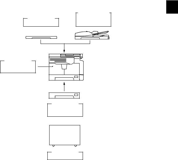
1.5System List
1
Automatic
Document Feeder
(ADF)
MR-2020
Expansion
Memory
GC-1240
Paper Feed
Unit (PFU)
MY-1027
Desk
MH-1640
Fig. 1-2
|
© 2009 TOSHIBA TEC CORPORATION All rights reserved |
e-STUDIO181/211 |
|
SPECIFICATIONS / ACCESSORIES / OPTIONS / SUPPLIES |
1 — 7
|
e-STUDIO181/211 |
© 2009 TOSHIBA TEC CORPORATION All rights reserved |
|
SPECIFICATIONS / ACCESSORIES / OPTIONS / SUPPLIES |
1 — 8
2.OUTLINE OF THE MACHINE
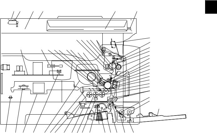
2.1Sectional View
1. Front side
|
A2 |
A3 |
A4 |
A1 |
A5 |
A6 |
||||||||||||||
|
J6 J7 J5 J4 |
J8 |
K5 |
|||||
|
J3 |
|||||||
|
K4 |
K2 |
I5 |
I9 F3 |
F2F1 |
H2 H3 |
J9 |
|
|
J1 |
|||||||
|
J2 |
|||||||
|
I7 |
|||||||
|
H4 |
|||||||
|
H5 |
|||||||
|
H1 |
|||||||
|
G2 |
|||||||
|
G1 |
|||||||
|
G3 |
|||||||
|
I1 |
|||||||
|
I2 |
|||||||
|
C5 |
|||||||
|
E2 |
|||||||
|
E1 |
E5
|
K3 |
B2 |
B1 |
K1 |
I8 |
I4 |
I11 I10 I3 |
I6 |
C3 |
C1 C2 C4 |
E4 |
||||
|
F4 |
E3 |
|||||||||||||
|
Fig. 2-1 |
|
A1 |
Original glass |
||
|
A2 |
ADF original glass |
||
|
A3 |
Contact image sensor unit (CIS) |
||
|
A4 |
Scanner damp heater (Left side) |
DH1 |
|
|
A5 |
Scanner damp heater (Right side) |
DH2 |
|
|
A6 |
Scanner damp heater thermostat |
THMO2 |
|
|
B1 |
Laser optical unit |
||
|
B2 |
Polygonal motor |
M4 |
|
|
C1 |
Pickup roller |
||
|
C2 |
Separation claw |
||
|
C3 |
Paper empty sensor |
S7 |
|
|
C4 |
Registration sensor |
S4 |
|
|
C5 |
Registration roller |
||
|
E1 |
Bypass pickup roller |
||
|
E2 |
Bypass feed roller |
||
|
E3 |
Bypass separation pad |
||
|
E4 |
Bypass paper sensor |
S8 |
|
|
E5 |
Bypass tray |
||
|
© 2009 TOSHIBA TEC CORPORATION All rights reserved |
e-STUDIO181/211 |
||
OUTLINE OF THE MACHINE |
2 — 1
|
F1 |
Needle electrode |
|
|
F2 |
Main charger |
|
|
F3 |
Main charger grid |
|
|
F4 |
Toner cartridge |
|
|
G1 |
Transfer charger wire |
|
|
G2 |
Separation charger wire |
|
|
G3 |
Transfer guide roller |
|
|
H1 |
Drum |
|
|
H2 |
Discharge LED |
|
|
H3 |
Drum cleaning blade |
|
|
H4 |
Recovery blade |
|
|
H5 |
Drum separation finger |
|
|
I1 |
Developer sleeve (Magnetic roller) |
|
|
I2 |
Mixer-1 |
|
|
I3 |
Mixer-2 |
|
|
I4 |
Mixer-3 |
|
|
I5 |
Doctor blade |
|
|
I6 |
Auto-toner sensor |
S6 |
|
I7 |
Toner recovery auger |
|
|
I8 |
Toner recycle auger |
|
|
I9 |
Drum thermistor |
THMS4 |
|
I10 |
Drum damp heater |
DH3 |
|
I11 |
Drum damp heater thermostat |
THMO3 |
|
J1 |
Fuser roller |
|
|
J2 |
Pressure roller |
|
|
J3 |
Fuser roller separation finger |
|
|
J4 |
Center heater lamp |
LAMP1 |
|
J5 |
Side heater lamp |
LAMP2 |
|
J6 |
Center/Side/Edge thermistor |
THMS1/2/3 |
|
J7 |
Fuser thermostat |
THMO1 |
|
J8 |
Exit roller |
|
|
J9 |
Exit sensor |
S5 |
|
K1 |
Front cover opening/closing switch |
SW4 |
|
K2 |
Front cover opening/closing interlock switch |
SW3 |
|
K3 |
Temperature/humidity sensor |
S3 |
|
K4 |
Switching regulator |
|
|
K5 |
ADU cover opening/closing interlock switch |
SW2 |
|
e-STUDIO181/211 |
© 2009 TOSHIBA TEC CORPORATION All rights reserved |
|
OUTLINE OF THE MACHINE |
2 — 2
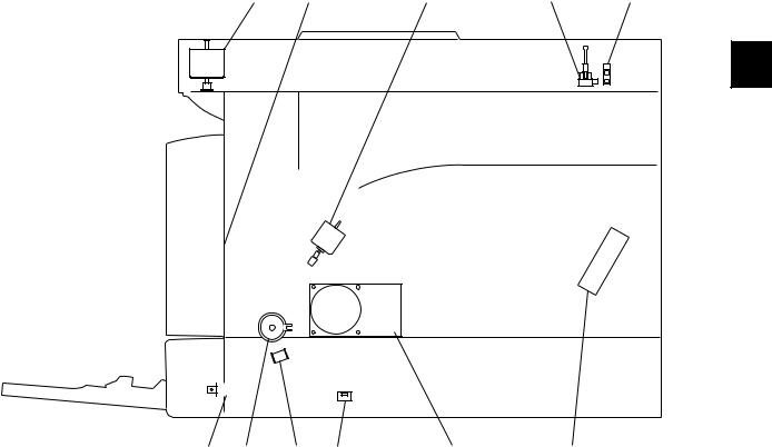
2. Rear side
|
M1 |
M5 |
M2 |
S2 |
S1 |
|
SOL2 CLT1 SOL1 SW5 |
M3 |
M6 |
Fig. 2-2
|
M1 |
Scan motor |
|
M2 |
Toner motor |
|
M3 |
Main motor |
|
M5 |
Exhaust fan |
|
M6 |
Switching regulator cooling fan |
|
S1 |
CIS home position sensor |
|
S2 |
Platen sensor |
|
SW5 |
Drawer detection switch |
|
CLT1 |
Registration clutch |
|
SOL1 |
Pickup solenoid |
|
SOL2 |
Bypass pickup solenoid |
|
© 2009 TOSHIBA TEC CORPORATION All rights reserved |
e-STUDIO181/211 |
|
OUTLINE OF THE MACHINE |
2 — 3
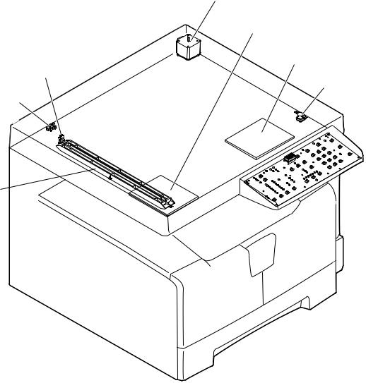
2.2Electric Parts Layout
2.2.1Scanner, control panel
M1
DH1
DH2
S1
THMO2
S2
CIS 

 LPNL
LPNL
Fig. 2-3
|
e-STUDIO181/211 |
© 2009 TOSHIBA TEC CORPORATION All rights reserved |
|
OUTLINE OF THE MACHINE |
2 — 4
![]()
2.2.2Power supply section, switches
SW3
SW2
PS
SW4
SW1
Fig. 2-4
|
© 2009 TOSHIBA TEC CORPORATION All rights reserved |
e-STUDIO181/211 |
|
OUTLINE OF THE MACHINE |
2 — 5

2.2.3Laser optical unit, fuser unit, toner cartridge section
S5
LAMP1
LAMP2
THMO1
THMS1
THMS2
THMS3
Fig. 2-5
|
e-STUDIO181/211 |
© 2009 TOSHIBA TEC CORPORATION All rights reserved |
|
OUTLINE OF THE MACHINE |
2 — 6

2.2.4Developer unit section
ERS
S6
THMS4
FUS
THMO3
DH3
Fig. 2-6
|
© 2009 TOSHIBA TEC CORPORATION All rights reserved |
e-STUDIO181/211 |
|
OUTLINE OF THE MACHINE |
2 — 7

2.2.5Driving section
CLT1
M3
SRAM
MAIN
SOL1
S4
Fig. 2-7
|
e-STUDIO181/211 |
© 2009 TOSHIBA TEC CORPORATION All rights reserved |
|
OUTLINE OF THE MACHINE |
2 — 8

Fig. 2-8
|
© 2009 TOSHIBA TEC CORPORATION All rights reserved |
e-STUDIO181/211 |
|
OUTLINE OF THE MACHINE |
2 — 9

2.2.7Bypass unit
S8
SOL2
Fig. 2-9
|
e-STUDIO181/211 |
© 2009 TOSHIBA TEC CORPORATION All rights reserved |
|
OUTLINE OF THE MACHINE |
2 — 10

2.3Symbols and Functions of Various Components
The column «P-I» shows the page and item number in the parts list. 1. Motors
|
Symbol |
Name |
Function |
Remarks |
P-I |
|
M1 |
SCAN-MOT |
Driving the CIS |
Fig. 2-3 |
10-1 |
|
Scan motor |
||||
|
M2 |
TNR-MOT |
Supplying the toner |
Fig. 2-5 |
12-15 |
|
Toner motor |
||||
|
M3 |
MAIN-MOT |
Driving the drum, developer unit, |
Fig. 2-7 |
12-2 |
|
Main motor |
registration roller, Pickup roller, feed |
|||
|
roller, cleaner unit |
||||
|
M4 |
M/DC-POL |
Driving the polygonal mirror |
Fig. 2-5 |
5-13 |
|
Polygonal motor |
||||
|
M5 |
EXT-FAN-MOT |
Exhausting ozone and cooling down |
Fig. 2-6 |
11-23 |
|
Exhaust fan |
the equipment inside |
|||
|
M6 |
PS-FAN-MOT |
Cooling down the switching regulator |
Fig. 2-4 |
5-11 |
|
Switching regulator cooling fan |
||||
|
© 2009 TOSHIBA TEC CORPORATION All rights reserved |
e-STUDIO181/211 |
|
OUTLINE OF THE MACHINE |
2 — 11
|
2. Sensors and switches |
||||
|
Symbol |
Name |
Function |
Remarks |
P-I |
|
S1 |
HOME-SNR |
Detecting CIS home position |
Fig. 2-3 |
9-101 |
|
CIS home position sensor |
||||
|
S2 |
PLTN-SNR |
Detecting the opening/closing of platen |
Fig. 2-3 |
9-101 |
|
Platen sensor |
cover or RADF |
|||
|
S3 |
TEMP/HUMI-SNR |
Detecting the temperature and humidity |
Fig. 2-4 |
5-16 |
|
Temperature/humidity sensor |
inside the equipment |
|||
|
S4 |
RGST-SNR |
Detecting the transporting paper at the |
Fig. 2-7 |
15-107 |
|
Registration sensor |
registration roller section |
|||
|
S5 |
EXIT-SNR |
Detecting the transporting paper at the |
Fig. 2-5 |
24-8 |
|
Exit sensor |
exit section |
|||
|
S6 |
ATTNR-SNR |
Detecting the density of toner in the |
Fig. 2-6 |
21-46 |
|
Auto-toner sensor |
developer unit |
|||
|
S7 |
EMP-SNR |
Detecting presence/absence of paper |
Fig. 2-8 |
15-107 |
|
Paper empty sensor |
in the drawer |
|||
|
S8 |
SFB-SNR |
Detecting presence/absence of paper |
Fig. 2-9 |
13-101 |
|
Bypass paper sensor |
on the bypass tray |
|||
|
SW1 |
MAIN-SW |
Turning ON/OFF of the equipment |
Fig. 2-4 |
5-4 |
|
Main switch |
||||
|
SW2 |
ADU-COV-INTLCK-SW |
Controlling cutoff and supply of the 24V |
Fig. 2-4 |
6-8 |
|
ADU cover opening/closing interlock |
voltage by opening/closing of the ADU |
|||
|
switch |
cover |
|||
|
SW3 |
FRNT-COV-INTLCK-SW |
Controlling cutoff and supply of the 24V |
Fig. 2-4 |
1-5 |
|
Front cover opening/closing interlock |
voltage by opening/closing of the front |
|||
|
switch |
cover |
|||
|
SW4 |
FRNT-COV-SW |
Detecting the opening/closing of the |
Fig. 2-4 |
1-101 |
|
Front cover opening/closing switch |
front cover |
|||
|
SW5 |
CST-SW |
Detecting presence/absence of the |
Fig. 2-8 |
16-110 |
|
Drawer detection switch |
drawer |
|||
3. Electromagnetic clutches
|
Symbol |
Name |
Function |
Remarks |
P-I |
|
CLT1 |
RGST-CLT |
Driving the registration roller |
Fig. 2-7 |
16-21 |
|
Registration clutch |
||||
4. Solenoids
|
Symbol |
Name |
Function |
Remarks |
P-I |
|
SOL1 |
CST-SOL |
Controlling the power transmission of |
Fig. 2-7 |
16-9 |
|
Pickup solenoid |
the feed roller |
|||
|
SOL2 |
SFB-SOL |
Controlling the power transmission of |
Fig. 2-9 |
14-15 |
|
Bypass pickup solenoid |
the bypass pickup roller |
|||
|
e-STUDIO181/211 |
© 2009 TOSHIBA TEC CORPORATION All rights reserved |
|
OUTLINE OF THE MACHINE |
2 — 12

|
5. |
PC boards |
|||||
|
Symbol |
Name |
Function |
Remarks |
P-I |
||
|
MAIN |
PWA-F-MAIN |
Controlling the whole system and |
Fig. 2-7 |
7-1 |
||
|
Main PC board (MAIN board) |
image processing |
|||||
|
SRAM |
PWA-F-SRAM |
Storing the setting information of the |
Fig. 2-7 |
7-33 |
2 |
|
|
SRAM PC board (SRAM board) |
equipment |
|||||
|
LDR |
PWA-F-LDR |
Driving the laser diode |
Fig. 2-5 |
5-13 |
||
|
Laser driving PC board (LDR board) |
||||||
|
SNS |
PWA-F-SNS |
Detecting the laser beam position |
Fig. 2-5 |
5-13 |
||
|
H-sync signal detection PC board |
||||||
|
(SNS board) |
||||||
|
LPNL |
PWA-F-LPNL |
Detecting the button entry and |
Fig. 2-3 |
4-15 |
||
|
Control panel PC board |
controlling LED on the control panel |
|||||
|
(LPNL board) |
||||||
|
CTIF |
PWA-F-CTIF |
Interface for detecting the toner |
Fig. 2-5 |
7-30 |
||
|
Toner cartridge interface PC board |
cartridge |
|||||
|
(CTIF board) |
(Detecting the CTRG board) |
|||||
|
CTRG |
PWA-F-CTRG |
Storing the status of the toner cartridge |
Fig. 2-5 |
103-3 |
||
|
Toner cartridge PC board |
||||||
|
(CTRG board) |
||||||
|
FUS |
PWA-F-FUS |
Supplying power to each damp heater |
Fig. 2-6 |
7-12 |
||
|
Fuse PC board (FUS board) |
* Optional for NAD/MJD/CND model, |
|||||
|
standard for other models |
6. Lamps and heaters
|
Symbol |
Name |
Function |
Remarks |
P-I |
|
LAMP1 |
CNTR-LAMP |
Heating the center section of the fuser |
Fig. 2-5 |
23-12 |
|
Center heater lamp |
roller |
|||
|
LAMP2 |
SIDE-LAMP |
Heating the section of both sides of the |
Fig. 2-5 |
23-13 |
|
Side heater lamp |
fuser roller |
|||
|
ERS |
LP-ERS |
Removing the residual charge from the |
Fig. 2-6 |
20-13 |
|
Discharge LED |
drum surface |
|||
|
DH1 |
SCN-DH-L |
Preventing condensation in the |
Fig. 2-3 |
9-17 |
|
Scanner damp heater (Left) |
scanner unit |
|||
|
* Optional for NAD/MJD/CND model, |
||||
|
standard for other models |
||||
|
DH2 |
SCN-DH-R |
Preventing condensation in the |
Fig. 2-3 |
9-18 |
|
Scanner damp heater (Right) |
scanner unit |
|||
|
* Optional for NAD/MJD/CND model, |
||||
|
standard for other models |
||||
|
DH3 |
DRM-DH |
Preventing condensation of the drum |
Fig. 2-6 |
8-6 |
|
Drum damp heater |
* Optional for NAD/MJD/CND model, |
|||
|
standard for other models |
||||
|
© 2009 TOSHIBA TEC CORPORATION All rights reserved |
e-STUDIO181/211 |
|
OUTLINE OF THE MACHINE |
2 — 13
7. Thermistors and thermostats
|
Symbol |
Name |
Function |
Remarks |
P-I |
|
THMS1 |
THMS-C-HTR |
Detecting the surface temperature at |
Fig. 2-5 |
23-6 |
|
Center thermistor |
the center of the fuser roller (for |
|||
|
controlling the center heater lamp) |
||||
|
THMS2 |
THMS-S-HTR |
Detecting the surface temperature at |
Fig. 2-5 |
23-6 |
|
Side thermistor |
the rear side of the fuser roller (for |
|||
|
controlling the side heater lamp) |
||||
|
THMS3 |
THMS-EDG-HTR |
Detecting the surface temperature at |
Fig. 2-5 |
23-6 |
|
Edge thermistor |
the edge of the rear side of the fuser |
|||
|
roller (for preventing overheating) |
||||
|
THMS4 |
THMS-DRM |
Detecting the temperature on the drum |
Fig. 2-6 |
21-49 |
|
Drum thermistor |
surface |
|||
|
THMO1 |
THERMO-FSR |
Preventing overheating in the fuser unit |
Fig. 2-5 |
23-5 |
|
Fuser thermostat |
||||
|
THMO2 |
THERMO-SCN-DH |
Preventing overheating of the scanner |
Fig. 2-3 |
9-20 |
|
Scanner damp heater thermostat |
damp heater |
|||
|
* Optional for NAD/MJD/CND model, |
||||
|
standard for other models |
||||
|
THMO3 |
THERMO-DRM-DH |
Preventing overheating of the drum |
Fig. 2-6 |
8-7 |
|
Drum damp heater thermostat |
damp heater |
|||
|
* Optional for NAD/MJD/CND model, |
||||
|
standard for other models |
||||
8. Others
|
Symbol |
Name |
Function |
Remarks |
P-I |
|
CIS |
CIS |
Reading originals |
Fig. 2-3 |
9-8 |
|
Contact image sensor unit |
||||
|
PS |
PS-ACC |
• Generating DC voltage and |
Fig. 2-4 |
5-2 |
|
Switching regulator |
supplying it to each section of the |
|||
|
equipment |
||||
|
• Generating high voltage and |
||||
|
supplying it to the main charger, |
||||
|
developer, transfer and separation |
||||
|
units |
||||
|
• Supplying AC power to the heater |
||||
|
lamp |
||||
|
e-STUDIO181/211 |
© 2009 TOSHIBA TEC CORPORATION All rights reserved |
|
OUTLINE OF THE MACHINE |
2 — 14
![]()
2.4General Description
2.4.1System block diagram
|
Solenoids |
Clutches |
Bypass unit |
||||||||||||||||||||||
|
I/O |
||||||||||||||||||||||||
|
Control panel |
Download JIG |
Sensors |
Switches |
Motors |
PFU |
Copy key card / |
Coin controller |
|||||||||||||||||
|
USB connector (device) |
16 |
SDRAM |
64 MB |
16 |
: Option |
|||||||||||||||||||
|
SRAM |
128 kB |
16 |
8 |
ASIC |
(I/O port) |
|||||||||||||||||||
|
SDRAM bus (16 bit) |
16 |
SDRAM |
16 MB |
SRAM board |
Battery |
CPU bus (16 bit) |
16 |
Flash ROM |
2 MB |
|||||||||||||||
|
SoC |
(System controller) |
|||||||||||||||||||||||
|
8 |
||||||||||||||||||||||||
|
AFE |
Driver |
D/A converter |
A/D converter |
|||||||||||||||||||||
|
MAIN board |
||||||||||||||||||||||||
|
DC |
DC |
(High voltage) |
||||||||||||||||||||||
|
ADF |
CIS |
Scan motor |
M |
Power supply unit |
AC LVPS |
HVPS |
Laser optical unit |
LDR board |
Laser diode ASIC |
SNS board |
Laser beam sensor |
Developer unit |
Auto-toner sensor |
Drum thermistor |
Temperature/humidity |
sensor |
Fuser unit |
Thermistors |
||||||
|
Fig. 2-10 |
|
© 2009 TOSHIBA TEC CORPORATION All rights reserved |
e-STUDIO181/211 |
|
OUTLINE OF THE MACHINE |
2 — 15

2.4.2Construction of boards
[ 1 ] Construction diagram of boards
This system consists of the following including the MAIN board as a main board.
|
Scanner unit |
Control panel |
||||||||||||||
|
CIS |
LPNL |
||||||||||||||
|
Toner cartridge |
|||||||||||||||
|
FUS |
SRAM |
||||||||||||||
|
MAIN |
CTIF |
CTRG |
|||||||||||||
|
HVPS |
|||||||||||||||
|
AC input |
PS-ACC |
Laser optical unit |
|||||||||||||
|
LVPS |
|||||||||||||||
|
LDR |
|||||||||||||||
|
Main switch |
Cover opening/closing |
SNS |
|||||||||||||
|
interlock switches |
|||||||||||||||
|
: DC power supply line |
|||||||||||||||
|
: AC power supply line |
|||||||||||||||
|
: Signal line |
|||||||||||||||
Fig. 2-11
[ 2 ] Function of each board
•MAIN board:
This is the board taking the leading part in all systems. It consists of the SoC, ASIC, memory (SDRAM, Flash ROM), etc. In the SoC (System control), which is a core of this MAIN board, the functions of the CPU, image processing, page memory control, CODEC, external interface (USB) control, etc. are embedded and performed by one chip.
Based on the data input from the control panel, the SoC controls each system, such as the ASIC, each memory, CIS unit and laser optical unit, and thus permitting the scanning of originals and the printing of data.
•SRAM board:
This is the board on which the SRAM for storing the user’s setting information and counter value and its backup function are mounted. When the MAIN board is replaced, attaching this board to the new MAIN board can assume the data of the previous equipment.
•LPNL board:
This is the board on which each button switch and LED on the control panel are mounted.
•CTRG board:
This is the board on which the IC chip for storing information about the toner cartridge (number of prints, identification data, etc.) is mounted.
•CTIF board:
This is the interface board with the CTRG board in the toner cartridge. Information written in the IC chip on the CTRG board is read into the SoC on the MAIN board through this board.
•LDR board:
This is the board on which the laser diode and the ASIC are mounted. The laser is emitted based on the image data signal output from the SoC on the MAIN board.
|
e-STUDIO181/211 |
© 2009 TOSHIBA TEC CORPORATION All rights reserved |
|
OUTLINE OF THE MACHINE |
2 — 16

|
• |
SNS board: |
|
|
This is the board on which the light sensor for detecting the radiating position of the laser is |
||
|
mounted. It outputs the H-sync signal to the SoC on the MAIN board. |
||
|
• |
PS-ACC: |
|
|
This is the unit to generate each DC (high/low) voltage, which is used in the equipment, from the |
2 |
|
|
external AC electric power input. This is then provided to each electric part. |
||
•FUS board:
This is the board to provide AC electric power for driving the damp heater.
*Optional for NAD/MJD/CND model, standard for other models.
•CIS:
This is the unit witch performs optical-to-electrical conversion to convert the light reflected by the original into the electrical signals. It consists of a light source (LEDs), optical system, CCD sensor, etc.
|
© 2009 TOSHIBA TEC CORPORATION All rights reserved |
e-STUDIO181/211 |
|
OUTLINE OF THE MACHINE |
2 — 17

2.5Disassembly and Replacement of Covers
2.5.1Front cover
(1)Open the front cover.
(2)Release the upper hinge.
(3)Take off the front cover while lifting it up.
2.5.2Inner tray
|
(1) Remove 2 screws and take off the Inner tray. |
Inner tray |
|
Fig. 2-13 |
2.5.3Left cover
(1)Take off the Inner tray.
P.2-18 «2.5.2 Inner tray»
(2)Remove 4 screws and take off the left cover.
|
e-STUDIO181/211 |
© 2009 TOSHIBA TEC CORPORATION All rights reserved |
|
OUTLINE OF THE MACHINE |
2 — 18

2.5.4Tray rear cover
(1)Take off the left cover.
P.2-18 «2.5.3 Left cover»
(2)Take off the tray rear cover.
|
2 |
Tray rear cover |
|
Fig. 2-15 |
2.5.5Front right cover
(1)Take off the front cover.
P.2-19 «2.5.5 Front right cover»
(2)Pull out the toner cartridge.
(3)Open the ADU cover.
(4)Remove 2 screws and take off the front right cover.
Front right cover
Fig. 2-16
2.5.6Front upper cover
(1)Remove 1 screw and take off the front upper cover.
Front upper cover |
|
Fig. 2-17 |
|
© 2009 TOSHIBA TEC CORPORATION All rights reserved |
e-STUDIO181/211 |
|
OUTLINE OF THE MACHINE |
2 — 19

2.5.7ADU cover
(1)Open the bypass tray.
(2)Open the ADU cover.
(3)Open the transfer unit and release the ADU stopper on the front side.
(4)Remove 1 screw and take off the ADU stopper on the rear side.
Note:
Be careful not to fall off the ADU cover when the screws are removed from the ADU stopper.
(5)Take off the ADU cover while sliding it toward the right.
|
ADU stopper |
ADU stopper |
|
Fig. 2-18 |
2.5.8Right front cover
(1)Take off the front cover.
P.2-18 «2.5.1 Front cover»
(2)Open the ADU cover.
(3)Pull out the drawer.
(4)Remove 2 screws and take off the right front cover.
Right front cover |
|
Fig. 2-20 |
|
e-STUDIO181/211 |
© 2009 TOSHIBA TEC CORPORATION All rights reserved |
|
OUTLINE OF THE MACHINE |
2 — 20

2.5.9Right rear cover
(1)Open the ADU cover.
(2)Remove 1 screw and take off the ADU stopper on the rear side.
(3)Take off the 2 screw and take off the right rear cover.
|
2 |
Right rear cover |
|
Fig. 2-21 |
2.5.10Rear cover
(1)Remove 5 screws and take off the rear cover.
|
© 2009 TOSHIBA TEC CORPORATION All rights reserved |
e-STUDIO181/211 |
|
OUTLINE OF THE MACHINE |
2 — 21

2.6Disassembly and Replacement of PC boards
Note:
If the PC board has to be replaced due to an operational defect, this may have been caused by a contact failure of the connector. Before replacing the board, disconnect and then reconnect the connector to check if this action eliminates the operational defect.
2.6.1MAIN board (MAIN)
(1) Take off the rear cover.
P.2-21 «2.5.10 Rear cover»
(2) Disconnect 15 connectors.
Note:
Connect the flat harness to the MAIN board with its erectrode side down. An error “CA2” will be displayed if the connection is incorrect.
Fig. 2-23
(3) Remove 6 screws and take off the MAIN board.
Notes:
1. When replacing the MAIN board, also attach the SRAM board to the new MAIN board from the old MAIN board.
2. Be sure to perform “08-389” after the SRAM board has been replaced.
3. Be sure to perform «05-310» with the platen cover or the ADF closed after replacing the MAIN board.
MAIN board
Fig. 2-24
|
e-STUDIO181/211 |
© 2009 TOSHIBA TEC CORPORATION All rights reserved |
|
OUTLINE OF THE MACHINE |
2 — 22

2.6.2SRAM board (SRAM)
(1)Take off the rear cover.
|
P.2-21 «2.5.10 Rear cover» |
|
|
(2) Release 1 lock support and take off the |
2 |
|
SRAM board. |
|
|
Notes: |
SRAM board |
|
1. Be sure to perform “08-388” after the |
|
|
SRAM board has been replaced. |
|
|
2. Perform «05-310» with the platen cover |
|
|
and the ADF closed after replacing the |
|
|
SRAM board. |
3.Make sure that the direction of the battery on the SRAM board is correct when replacing it.
|
Fig. 2-25 |
|
SRAM board |
|
Battery |
|
Fig. 2-26 |
|
© 2009 TOSHIBA TEC CORPORATION All rights reserved |
e-STUDIO181/211 |
|
OUTLINE OF THE MACHINE |
2 — 23

2.6.3Fuse PC board (FUS)
Note:
This fuse PC board is copacked with the damp heater unit. (The damp heater unit is optional for NAD, CND and MJD.)
(1)Take off the rear cover.
P.2-21 «2.5.10 Rear cover»
(2)Remove 2 screws and take off the cover.
(3)Disconnect 2 connectors, remove 1 screw, and then take off the fuse PC board by lifting it up.
|
Connector |
|
Fuse PC board |
|
Fig. 2-28 |
2.6.4Switching regulator unit (PS)
|
Note: |
|
|
When the fuse PC board is installed as |
|
|
options, remove the rear cover ( |
P.2-21 |
|
«2.5.10 Rear cover») and disconnect |
|
|
connectors before performing the |
|
|
procedure below. |
|
|
Connector |
|
|
Fig. 2-29 |
|
e-STUDIO181/211 |
© 2009 TOSHIBA TEC CORPORATION All rights reserved |
|
OUTLINE OF THE MACHINE |
2 — 24
 Loading…