-
Contents
-
Table of Contents
-
Bookmarks
Quick Links
FILE NO. SVM-07034
SERVICE MANUAL
SPLIT TYPE
Indoor Unit
<High Wall, Heat Pump Type>
RAS-M10SKV-E
RAS-M13SKV-E
RAS-M16SKV-E
<High Wall, Cooling Type>
RAS-M10SKCV-E
RAS-M13SKCV-E
RAS-M16SKCV-E
R410A
July, 2007
Related Manuals for Toshiba RAS-M10SKV-E
Summary of Contents for Toshiba RAS-M10SKV-E
-
Page 1: Service Manual
FILE NO. SVM-07034 SERVICE MANUAL SPLIT TYPE Indoor Unit <High Wall, Heat Pump Type> RAS-M10SKV-E RAS-M13SKV-E RAS-M16SKV-E <High Wall, Cooling Type> RAS-M10SKCV-E RAS-M13SKCV-E RAS-M16SKCV-E R410A July, 2007…
-
Page 2: Table Of Contents
CONTENTS 1. SAFETY PRECAUTIONS …………….3 2. SPECIFICATIONS ………………5 3. REFRIGERANT R410A …………….8 4. CONSTRUCTION VIEWS ……………. 16 5. WIRING DIAGRAM ……………… 17 6. SPECIFICATIONS OF ELECTRICAL PARTS ……… 19 7. REFRIGERANT CYCLE DIAGRAM …………20 8. CONTROL BLOCK DIAGRAM …………..21 9.
-
Page 3: Safety Precautions
1. SAFETY PRECAUTIONS For general public use Power supply cord of outdoor unit shall be more than 1.5 mm (H07RN-F or 60245IEC66) polychloroprene sheathed flexible cord. • Read this “SAFETY PRECAUTIONS” carefully before servicing. • The precautions described below include the important items regarding safety. Observe them without fail. •…
-
Page 4
• DO NOT INSTALL NEAR CONCENTRATIONS OF COMBUSTIBLE GAS OR GAS VAPORS. FAILURE TO FOLLOW THIS INSTRUCTION CAN RESULT IN FIRE OR EXPLOSION. • TO PREVENT THE INDOOR UNIT FROM OVERHEATING AND CAUSING A FIRE HAZARD, PLACE THE UNIT WELL AWAY (MORE THAN 2 M) FROM HEAT SOURCES SUCH AS RADIATORS, HEAT REGISTORS, FURNACE, STOVES, ETC. -
Page 5: Specifications
RAS-4M27GACV-E outdoor unit : Combination available X : Combination unavailable This service manual describes about M∗∗ SKV-E series indoor units, RAS-M10SKV-E,RAS-M13SKV-E, RAS-M16SKV-E,RAS-M10SKCV-E,RAS-M13SKCV-E and RAS-M16SKCV-E only. For the multi outdoor unit to be combined, refer to the service manual. Outdoor unit…
-
Page 6
2− 2. Specifications Unit model Indoor RAS-M10SKV-E, RAS-M13SKV-E, RAS-M16SKV-E Outdoor Cooling capacity (kW) Cooling capacity range (kW) Heating capacity (kW) Heating capacity range (kW) Power supply 220~240V-1Ph-50Hz / 220V-1Ph-60Hz RAS-M10SKV-E RAS-M13SKV-E RAS-M16SKV-E Electric Indoor Unit model characteristic Running current 0.21-0.19 0.21-0.19… -
Page 7
Unit model Indoor RAS-M10SKCV-E, RAS-M13SKCV-E, RAS-M16SKCV-E Outdoor Cooling capacity (kW) Cooling capacity range (kW) Heating capacity (kW) Heating capacity range (kW) Power supply 220~240V-1Ph-50Hz / 220V-1Ph-60Hz RAS-M10SKCV-E RAS-M13SKCV-E RAS-M16SKCV-E Electric Indoor Unit model 0.21-0.19 0.21-0.19 0.21-0.19 characteristic Running current Power consumption Power factor Cooling Heating… -
Page 8: Refrigerant R410A
3. REFRIGERANT R410A This air conditioner adopts the new refrigerant HFC 6. When an air conditioning system charged with a (R410A) which does not damage the ozone layer. large volume of refrigerant is installed in a small room, it is necessary to exercise care so that, The working pressure of the new refrigerant R410A even when refrigerant leaks, its concentration is 1.6 times higher than conventional refrigerant…
-
Page 9
Table 3-2-1 Thicknesses of annealed copper pipes Thickness (mm) Nominal diameter Outer diameter (mm) R410A 6.35 0.80 0.80 9.52 0.80 0.80 12.70 0.80 0.80 15.88 1.00 1.00 2. Joints For copper pipes, flare joints or socket joints are used. Prior to use, be sure to remove all contaminants. a) Flare Joints Flare joints used to connect the copper pipes cannot be used for pipings whose outer diameter exceeds 20 mm. -
Page 10
d) Flare Processing Make certain that a clamp bar and copper pipe have been cleaned. ØD By means of the clamp bar, perform the flare processing correctly. Use either a flare tool for R410A or conven- tional flare tool. Flare processing dimensions differ according to the type of flare tool. -
Page 11
Table 3-2-6 Flare and flare nut dimensions for R22 Dimension (mm) Nominal Outer diameter Thickness Flare nut width diameter (mm) (mm) (mm) 6.35 9.52 13.0 13.5 12.70 16.2 16.0 12.9 15.88 19.7 19.0 16.0 19.05 23.3 24.0 19.2 Fig. 3-2-2 Relations between flare nut and flare seal surface 2. -
Page 12
3-3. Tools 3-3-1. Required Tools The service port diameter of packed valve of the outdoor unit in the air-water heat pump using R410A is changed to prevent mixing of other refrigerant. To reinforce the pressure-resisting strength, flare processing dimensions and opposite side dimension of flare nut (For Ø12.7 copper pipe) of the refrigerant piping are lengthened. -
Page 13: Recharging Of Refrigerant
3-4. Recharging of Refrigerant When it is necessary to recharge refrigerant, charge the specified amount of new refrigerant according to the following steps. Recover the refrigerant, and check no refrigerant remains in the equipment. When the compound gauge’s pointer has indicated –0.1 Mpa (–76 cmHg), place the handle Low in the fully closed position, and turn off the vacuum pump’s power switch.
-
Page 14
1. Be sure to make setting so that liquid can be charged. 2. When using a cylinder equipped with a siphon, liquid can be charged without turning it upside down. It is necessary for charging refrigerant under condition of liquid because R410A is mixed type of refrigerant. Accordingly, when charging refrigerant from the refrigerant cylinder to the equipment, charge it turning the cylinder upside down if cylinder is not equipped with siphon. -
Page 15
2. Characteristics required for flux 3-5-3. Brazing • Activated temperature of flux coincides with the As brazing work requires sophisticated techniques, brazing temperature. experiences based upon a theoretical knowledge, it must be performed by a person qualified. • Due to a wide effective temperature range, flux is hard to carbonize. -
Page 16: Construction Views
4. CONSTRUCTION VIEWS RAS-M10SKV-E, RAS-M13SKV-E, RAS-M16SKV-E RAS-M10SKCV-E, RAS-M13SKCV-E, RAS-M16SKCV-E Air inlet Air filter Front panel Heat exchanger Knock out system Knock out system Installation plate hanger Wireless remote controller Installation plate hanger Drain hose (0.50m) Connecting pipe (0.35m) Connecting pipe (0.40m) (For 10,13 series;…
-
Page 17: Wiring Diagram
5. WIRING DIAGRAM 5-1. RAS-M10SKV-E, RAS-M13SKV-E, RAS-M10SKCV-E, RAS-M13SKCV-E – 17 –…
-
Page 18
5-2. RAS-M16SKV-E RAS-M16SKCV-E – 18 –… -
Page 19: Specifications Of Electrical Parts
6. SPECIFICATIONS OF ELECTRICAL PARTS Indoor Unit Parts name Type Specifications M10SKV-E, M13SKV-E Fan motor AFS-220-20-4AR AC240V, 20W M10SKCV-E, M13SKCV-E (for indoor) ICF-340-30-2B M16SKV-E, M16SKCV-E DC 340V, 30W ( − ) Ω Room temp. sensor (TA-sensor) at 25°C − Heat exchanger temp. sensor (TC-sensor) 10kΩ…
-
Page 20: Refrigerant Cycle Diagram
7. REFRIGERANT CYCLE DIAGRAM Temp. measurement INDOOR UNIT Indoor heat exchanger Cross flow fan : ∗1 Max. : ∗1 Min. Pressure measurement Chargeless : ∗1 Deoxidized copper pipe Charge : ∗1 Gauge attaching port Outer dia. : 6.35mm Vacuum pump connecting port Thickness : 0.8mm Sectional shape Deoxidized copper pipe…
-
Page 21: Control Block Diagram
8. CONTROL BLOCK DIAGRAM 8-1. Indoor Unit RAS-M10SKV-E, RAS-M13SKV-E, RAS-M16SKV-E Indoor Unit Control Unit M.C.U. Heat Exchanger Sensor (Tcj) Louver Functions Motor Heat Exchanger Sensor (Tc) Heat Exchanger Sensor (Tc) • Cold draft preventing Function Room Temperature Sensor (Ta) Louver Motor •…
-
Page 22
RAS-M10SKCV-E, RAS-M13SKCV-E, RAS-M16SKCV-E Indoor Unit Control Unit M.C.U. Heat Exchanger Sensor (Tcj) Louver Functions Motor Heat Exchanger Sensor (Tc) • Cold draft preventing Function Room Temperature Sensor (Ta) Louver Motor • 3-minute Delay at Restart for Compressor Drive Control Infrared Rays Signal Receiver •… -
Page 23: Operation Description
9. OPERATION DESCRIPTION 9-1. Outline of Air Conditioner Control • Detection of inverter input current and current release operation This air conditioner is a capacity-variable type air • Over-current detection and prevention operation conditioner, which uses AC or DC motor for the indoor to IGBT module (Compressor stop function) for motor and the outdoor fan motor.
-
Page 24
9-2. Operation Description 1. Basic operation ………………….25 1. Operation control ………………..25 2. Operating mode selection when performing 2-room operation ……26 3. Cooling/Heating operation ………………26 4. AUTO operation ………………..27 5. DRY operation ………………….. 27 2. Indoor fan motor control ………………… 28 Capacity control …………………. -
Page 25: Basic Operation
Item Operation flow and applicable data, etc. Description 1. Basic 1. Operation control operation Receiving the user’s operation condition setup, the operation statuses of indoor/outdoor units are controlled. 1) The operation conditions are selected by the remote controller as shown in the below. 2) A signal is sent by ON button of the remote controller.
-
Page 26: Operating Mode Selection When Performing 2-Room Operation
Item Operation flow and applicable data, etc. Description 1. Basic 2. Operating mode selection when performing 2-room operation operation 1) The outdoor unit operation mode conforms to the instructions of the indoor unit that was pressed first. 2) When combined operation consisting of cooling (dry) and heating, fan and heating, or cleaning operation and heating is performed, operation conforms to the instructions of the indoor unit that was pressed first as shown in the following table.
-
Page 27: Auto Operation
Item Operation flow and applicable data, etc. Description 1. Basic 4. AUTO operation 1) Detects the room temperature (Ta) when operation the operation started. Selection of operation mode As shown in the following figure, the operation starts by 2) Selects an operation mode from Ta in selecting automatically the status of room temperature the left figure.
-
Page 28: Indoor Fan Motor Control
*5 : Fan speed = (M + –L) x 1/4 + L +1.0 +0.5 (Linear approximation L(W6) from M+ and L) (Table 1) Indoor fan air flow rate Fan speed RAS-M13SKV-E RAS-M10SKV-E RAS-M16SKV-E RAS-M10SKCV-E RAS-M13SKCV-E RAS-M16SKCV-E level COOL HEAT DRY Fan speed Air flow rate…
-
Page 29
Item Operation flow and applicable data, etc. Description 2. Indoor fan <In heating operation> 1) When setting the fan speed to L, motor control L+, M, M+ or H on the remote controller, the operation is per- formed with the constant speed HEAT ON shown in Fig. -
Page 30: Capacity Control
Item Operation flow and applicable data, etc. Description 3. Capacity The cooling or heating capacity depending on the load is 1) The difference between set control adjusted. temperature on remote controller (Ts) and room temperature (Ta) According to difference between the setup value of tempera- is calculated.
-
Page 31: Release Protective Control By Temperature Of Indoor Heat Exchanger
Item Operation flow and applicable data, etc. Description 4. Release protective <In cooling/dry operation> 1) When temperature of the indoor control by tempera- heat exchanger drops below 5°C, (Prevent-freezing control for indoor heat exchanger) ture of indoor heat the compressor speed is In cooling/dry operation, the sensor of indoor heat exchanger reduced.
-
Page 32: Louver Control
Item Operation flow and applicable data, etc. Description 5. Louver control This function controls the air direction of the indoor unit. • The position is automatically controlled according to the operation 1) Louver position mode (COOL/HEAT). • The set louver position is stored in memory by the microcomputer, and the louver returns to the stored position when the next operation is performed.
-
Page 33: Eco Operation
Item Operation flow and applicable data, etc. Description 6. ECO When pressing [ECO] button on the remote controller, a <Cooling operation> operation Economic operation is performed. 1) The control target temperature <Cooling operation> increase 0.5ºC per hour up to 2ºC This function operates the air conditioner with the difference starting from the set temperature between the set and the room temperature as shown in the…
-
Page 34: Temporary Operation
Item Operation flow and applicable data, etc. Description 7. Temporary Pressing [RESET] button starts the temporary opera- 1) When pressing [RESET] button, the operation tion of [AUTO] operation. When keeping [RESET] temporary [AUTO] operation starts. button pressed for 10 seconds or more, the temporary 2) When keeping [RESET] button pressed [COOL] operation is performed.
-
Page 35: Self-Cleaning Function
Item Operation flow and applicable data, etc. Description 8. Self-Cleaning 1. Purpose function The Self-Cleaning operation is to minimize the growth of mold, bacteria etc. by running the fan and drying so as to keep the inside of the air conditioner clean. Unit now performing cooling or dry operation Self-Cleaning operation When the cooling or dry operation shuts…
-
Page 36: Selt-Cleaning Function Release
Item Operation flow and applicable data, etc. Description • Self-Cleaning diagram 8. Self-Cleaning function Operation display FCU fan rpm is depend on presetting. (500RPM) FCU louver OPEN OPEN (12.7º) CLOSE ON or OFF ON or OFF Timer display depend on presetting of timer function. depend on presetting of timer function.
-
Page 37: Remote-A Or B Selection
Item Operation flow and applicable data, etc. Description 10. Remote-A or B Setting the remote controller 1. Purpose selection This operation is to operate only one To separate using of remote control for each indoor unit in case of 2 air conditioner are installed nearly. indoor unit using one remote controller.
-
Page 38: Quiet Mode
Item Operation flow and applicable data, etc. Description 11. QUIET mode When the [QUIET] button is pressed, the fan of the Quiet mode is the system which, control the indoor unit will be restricted the revolving speed at revolving speed of indoor fan to work −…
-
Page 39: One-Touch Comfort
Item Operation flow and applicable data, etc. Description 14. One-Touch One touch comfort is the fully automated operation Operation condition for model to Europe Comfort that is set according to the preferable condition in market a region. When an indoor unit receives «One Touch Comfort Signal»…
-
Page 40: Auto Restart Function
9-3. Auto Restart Function This indoor unit is equipped with an automatic restarting function which allows the unit to restart operating with the set operating conditions in the event of a power supply being accidentally shut down. The operation will resume without warning three minutes after power is restored. This function is not set to work when shipped from the factory.
-
Page 41: How To Cancel The Auto Restart Function
9-3-2. How to Cancel the Auto Restart Function To cancel auto restart function, proceed as follows : Repeat the setting procedure : the unit receives the signal and beeps three times. The unit will be required to be turned on with the remote controller after the main power supply is turned off. •…
-
Page 42: Remote Controller And Its Fuctions
The coutomised settings control temperature air flow strength, air flow direction and other settings to provide you alternate contact with «ONE-TOUCH» OF THE BUTTON. If you prefer other settings you can select from the many other operation functions of your Toshiba unit Press ONE-TOUCH : Start the operaton.
-
Page 43
4. DRY OPERATION (COOLING ONLY) For dehumidification, a moderate cooling performance is controlled automatically. 1. Press MODE : Select Dry 2. Press MODE : Set the desired temperature. 5. Hi-POWER OPERATION To automatically control room temperature and airflow for faster cooling or heating operation (except in DRY and FAN ONLY mode) Press HI-POWER : Start and stop the operation. -
Page 44
9. PRESET OPERATION Set your preferred operation for future use. The setting will be memorized by the unit for future operation (except air flow direction). 1. Select your preferred operation. 2. Press and hold PRESET for 3 seconds to memorize the setting. The mark displays. -
Page 45: Name And Functions Of Indications On Remote Controller
9-4-3. Name and Functions of Indications on Remote Controller [Display] All indications, except for the clock time indicator, are displayed by pressing the button. Transmission mark TIMER and clock time indicator This transmission mark indicates when the The time setting for timer operation or the clock remote controller transmits signals to the indoor time is indicated.
-
Page 46
9-5. Intermittent Operation Control for Indoor Fans of the Indoor Unit at Thermo-off Side in Heating Operation While heating operation is executed in two rooms, if room temperature reached the setup temperature in one room and thermo-off occurred, the following operations start. (Refer to the figure belox.) 1. -
Page 47: Installation Procedure
10. INSTALLATION PROCEDURE 10-1. Installation Diagram of Indoor and Outdoor Units Before installing the wireless remote controller • Loading Batteries 1. Remove the battery cover. 2. Insert 2 new batteries (AAA type) following the (+) and (− ) positions. 3 Batteries 2 Wireless remote controller –…
-
Page 48
Parts name Q’ty Refrigerant piping Indoor unit name Liquid side (Outer diameter) Gas side (Outer diameter) 1 ea. RAS-M10SKV-E, M10SKCV-E 6.35 mm 9.52 mm RAS-M13SKV-E, M13SKCV-E RAS-M16SKV-E, M16SKCV-E 6.35 mm 12.7 mm Shield pipe (for extension drain hose) (polyethylene foam, 6 mm thick) 10-2-2. -
Page 49
10-2-3. Installation/Servicing Tools Changes in the product and components In the case of an air conditioner using R410A, in order to prevent any other refrigerant from being charged accidentally, the service port diameter of the outdoor unit control valve (3 way valve) has been changed. (1/2 UNF 20 threads per inch) •… -
Page 50: Indoor Unit
10-3. Indoor Unit 10-3-2. Drilling a Hole and Mounting Instal- lation Plate 10-3-1. Installation Place • A place which provides enough spaces around the Drilling a hole indoor unit as shown in the diagram. When install the refrigerant pipes from the rear. •…
-
Page 51
10-3-3. Electrical Work When the installation plate is directly mounted on the wall 1. The supply voltage must be the same as the rated voltage of the air conditioner. 1. Securely fit the installation plate onto the wall by 2. Prepare a power source for the exclusive use of screws with the upper and lower catches, that the air conditioner. -
Page 52
10-3-5. Piping and Drain Hose Installation CAUTION CAUTION Piping and drain hose forming • Be sure to refer to the wiring system diagram labeled inside the front panel. • Since condensation results in machine trouble, • Check local electrical regulations for any make sure to insulate both the connecting pipes specific wiring instructions or limitations. -
Page 53
How to attach the drain cap In case of bottom right or bottom left piping 1. Insert hexagonal wrench (4 mm). • After making slits on the front panel with a knife or similar tool, cut them out with a pair of nippers or an equivalent tool. -
Page 54
10-3-7. Drainage CAUTION 1. Run the drain hose at a downward sloped angle. • Bind the auxiliary pipes (two) and connecting cable with facing tape tightly. NOTE : In case of leftward piping and rear-leftward • Hole should be made at a slight downward slant piping, bind the auxiliary pipes (two) only with on the outdoor side. -
Page 55: How To Diagnose The Trouble
11. HOW TO DIAGNOSE THE TROUBLE 11-1. First Confirmation 11-1-1. Confirmation of Power Supply Confirm that the power breaker operates (ON) normally. 11-1-2. Confirmation of Power Voltage Confirm that power voltage is AC 220–230–240 ± 10%. If power voltage is not in this range, the unit may not operate normally. 11-1-3.
-
Page 56: Primary Judgment
11-2. Primary Judgment To diagnose the troubles, use the following methods. 1) Judgment by flashing LED of indoor unit 2) Self-diagnosis by service check remote controller 3) Judgment of trouble by every symptom Firstly use the method 1) for diagnosis. Then, use the method 2) or 3) to diagnose the details of troubles. 11-3.
-
Page 57
Press [CHECK] button with a tip of pencil to set the remote controller to the service mode. • “ ” is indicated on the display of the remote controller. TOSHIBA Press [ON ] or [OFF ] button If there is no fault with a code, the indoor unit will beep… -
Page 58: Check Codes
11-4-2. Caution at Servicing 1. After servicing, press the START/STOP button to return to the normal mode. 2. After servicing by the check code, turn off breaker of the power supply, and turn on breaker of the power supply again so that memory in the microcomputer returns the initial status. However, the check codes are not deleted even if the power supply is turned off because they are stored in the fixed memory.
-
Page 59
Block distinction Operation of diagnosis function Judgment and action Check Check Block Cause of operation conditioner Remarks code code status Outdoor P.C. Inverter over-current All off Displayed when Even if trying operation again, all board protective circuit error is detected. operations stop immediately. -
Page 60: Judgment Of Trouble By Every Symptom
11-5. Judgment of Trouble by Every Symptom 11-5-1. Indoor Unit (Including Remote Controller) (1) Power is not turned on (Does not operate entirely) <Primary check> 1. Is the supply voltage normal? 2. Is the normal voltage provided to the outdoor unit? 3.
-
Page 61
( RAS-M16 Series ) Operation Check Item Considerable principle cause Turn off power supply once, and Measures 5 second later, turn it on again. Item by symptoms Is OPERATION indicator flashing? Is it possible to turn on Does transmission mark power supply by pushing on remote controller flash Remote controller is defective. -
Page 62
(3) Only the indoor motor fan does not operate <Primary check> 1. Is it possible to detect the power supply voltage (AC220–240V) between on the terminal block? 2. Does the indoor fan motor operate in cooling operation? (In heating operation, the indoor fan motor does not operate for approximately 10 minutes after it is turned on, to prevent a cold air from blowing in.) ( RAS-M10,13 Series ) Turn off power… -
Page 63
( RAS-M16 Series ) Turn off power supply once, and turn it on again. Is it possible to detect DC 1V or more between Does fan motor + and – of continue to operate? Peplace indoor motor connector (CN31). fan motor. Start to operate indoor unit in cooling operation at airflow… -
Page 64
(4) Indoor fan motor automatically starts to rotate by turning on power supply (For DC fan motor in RAS-M16SKV-E, RAS-M16SKCV-E) <Cause> The IC is built in the indoor fan motor. Therefore the P.C. board is also mounted to inside of the motor. If the P .C. -
Page 65
(For AC fan motor in RAS-M10,13SKV-E, RAS-M10,13SKCV-E) <Inspection procedure> 1. Remove the front panel. (Remove 2 screws.) 2. Remove the cover of the fan motor lead wires. 3. Check AC voltage with CN31 connector while the fan motor is rotating. NOTE : •… -
Page 66
(5) Troubleshooting for remote controller <Primary check> Check that A or B selected on the main unit is matched with A or B selected on the remote controller. The unit does not beep at all. Push the START/STOP button. Operation lamp on indoor unit is not indicated. -
Page 67
11-5-2. Wiring Failure (Interconnecting and Serial Signal Wire) (1) Outdoor unit does not operate 1) Is the voltage between of the indoor terminal block varied? Confirm that transmission from indoor unit to outdoor unit is correctly performed based upon the follow- ing diagram. -
Page 68: How To Check Simply The Main Parts
11-9. How to Check Simply the Main Parts 11-9-1. How to Check the P.C. Board (Indoor Unit) (1) Operating precautions 1) When removing the front panel or the P .C. board, be sure to shut off the power supply breaker. 2) When removing the P .C.
-
Page 69
(3) Check procedures ( RAS-M10,13 Series ) Table 11-9-1 Procedure Check points Causes Turn off the power supply breaker Check whether or not the fuse (F01) Impulse voltage was applied or the and remove the P.C. board is blown. indoor fan motor short-circuited. assembly from electronic parts base. -
Page 70
( RAS-M16 Series ) Table 11-9-1 Procedure Check points Causes Turn off the power supply breaker Check whether or not the fuse (F01) Impulse voltage was applied or the and remove the P.C. board is blown. indoor fan motor short-circuited. assembly from electronic parts base. -
Page 71
11-9-2. P .C . Board Layout ( RAS-M10, 13 Series ) +12V [1] Sensor characteristic table TA, TC, TCJ TA : Room temp. sensor TC : Heat exchanger temp. sensor TCJ : Heat exchanger temp. sensor Temperature (˚C) – 71 –… -
Page 72
( RAS-M16 Series ) +12V [1] Sensor characteristic table TA, TC, TCJ TA : Room temp. sensor TC : Heat exchanger temp. sensor TCJ : Heat exchanger temp. sensor Temperature (˚C) – 92 –… -
Page 73
11-9-3. Indoor Unit (Other Parts) Part name Checking procedure Room temp. (TA) sensor Disconnect the connector and measure the resistance value with tester. Heat exchanger (TC, TCJ) (Normal temp.) sensor Temperature 10°C 20°C 25°C 30°C 40°C Sensor TCJ, TA, TC (kΩ) 20.7 12.6 10.0… -
Page 74: How To Replace The Main Parts
12. HOW TO REPLACE THE MAIN PARTS WARNING • Since high voltages pass through the electrical parts, turn off the power without fail before proceeding with the repairs. Electric shocks may occur if the power plug is not disconnected. • After the repairs have been completed (after the front panel and cabinet have been installed), perform a test run, and check for smoking, unusual sounds and other abnormalities.
-
Page 75
Part name Procedures Remarks Front panel 5) Remove the front panel fixing screws. (2 pcs.) 6) Take off three hooks of panel from rear side. 2 Screws Three hooks <How to assemble the front panel> 1) Press three center positions and two lower center positions of the air outlet, and then hang the hanging hooks (3 pcs.) at the top side of the front panel to the rear plate. -
Page 76
Part name Procedures Remarks ‚ Electric parts 1) Follow the procedure up to 3) in above. box assembly 2) Remove screw of earth lead attached to the end plate of the evaporator. 3) Remove the lead wire cover, and remove connector for the fan motor and connec- tor for the louver motor from the electric parts box assembly. -
Page 77
Part name Procedures Remarks Horizontal louver 1) Remove shaft of the horizontal louver from the back body. (First remove the left shaft, and then remove other shafts while sliding the horizontal louver leftward.) Evaporator 1) Follow to the procedure in the item (Heat exchanger) 2) Remove the pipe holder from the rear side of the main unit. -
Page 78
Part name Procedures Remarks 1) Follow to the procedure in the item 4. Bearing 2) Remove the two screws used to secure the bearing base. Two screws 3) Remove the bearing base. <Caution at assembling> • If the bearing is out from the housing, push it into the specified position and then incorporate it in the main body. -
Page 79
Part name Procedures Remarks 1) Follow to the procedure till item 4. Fan motor 2) Loosen the set screw of the cross flow fan. 3) Remove two fixing screws of the motor cover and them remove the motor cover. 4) Remove two more fixing screws of the motor band and remove the motor band. -
Page 80
Part name Procedures Remarks Cross flow fan <Caution at reassembling> 5 mm 1) To incorporate the fan motor, remove the fan motor rubber (at shaft core side), incorporate the motor into the position in the following figure, and then install the fan motor. •… -
Page 81
12-2. Microcomputer Part name Procedure Remarks Common procedure 1) Turn the power supply off to stop the Replace terminal block, operation of air-conditioner. microcomputer ass’y and the P .C. board ass’y. 2) Remove the front panel. • Remove the 2 fixing screws. 3) Remove the electrical part base. -
Page 82
( RAS-M16 Series ) L01 C01 CN23 FUSE CN10 DB01 IC01 IC03 – 82 –… -
Page 83: Exploded Views And Parts List
13. EXPLODED VIEWS AND PARTS LIST 13-1. Indoor Unit (1) Location Part Location Part Description Description 43T21397 LOUVER MOTOR 43T39327 BEARING BASE 43T21371 FAN MOTOR 43T39328 MOTOR BAND (LEFT) (FOR RAS-M16SKV-E,SKCV-E) 43T39329 MOTOR BAND (RIGHT) 43T21393 FAN MOTOR 43T09409 HORIZONTAL LOUVER (FOR RAS-M10,13SKV-E,SKCV-E) 43T79313 DRAIN CAP…
-
Page 84
TEMPERATURE SENSOR 43T69670 PC BOARD (FOR RAS-M16SKV-E) 43T50306 TEMPERATURE SENSOR 43T69671 PC BOARD (FOR RAS-M16SKCV-E) 43T60002 TERMINAL BLOCK; 3P 43T69672 PC BOARD (FOR RAS-M10SKV-E) 43T50318 TEMPERATURE SENSOR 43T69673 PC BOARD (FOR RAS-M13SKV-E) 43T62003 CORD CLAMP 43T69674 PC BOARD (FOR RAS-M10SKCV-E) 43T69633… -
Page 85
(THAILAND) CO.,LTD. 144/9 MOO 5, BANGKADI INDUSTRIAL PARK, TIVANON ROAD, TAMBOL BANGKADI, AMPHUR MUANG, PATHUMTHANI 12000, THAILAND.

Кондиционеры Toshiba RAS-M10SKV-E — инструкция пользователя по применению, эксплуатации и установке на русском языке. Мы надеемся, она поможет вам решить возникшие у вас вопросы при эксплуатации техники.
Вы можете скачать инструкцию к Toshiba RAS-M10SKV-E по ссылке ниже, если не хотите ждать загрузки. Если остались вопросы, задайте их в комментариях после инструкции.
«Загружаем инструкцию», означает, что нужно подождать пока файл загрузится и можно будет его читать онлайн. Некоторые инструкции очень большие и время их появления зависит от вашей скорости интернета.
Полезные видео
Характеристики
Остались вопросы?
Не нашли свой ответ в руководстве или возникли другие проблемы? Задайте свой вопрос в форме ниже с подробным описанием вашей ситуации, чтобы другие люди и специалисты смогли дать на него ответ. Если вы знаете как решить проблему другого человека, пожалуйста, подскажите ему


Часто задаваемые вопросы

Как посмотреть инструкцию к Toshiba RAS-M10SKV-E?
Необходимо подождать полной загрузки инструкции в сером окне на данной странице или скачать кликнув по специальной кнопке.
Руководство на русском языке?
Все наши руководства представлены на русском языке или схематично, поэтому вы без труда сможете разобраться с вашей моделью
Как можно распечатать инструкцию?
Скачайте ее по специальной кнопке над формой чтения на ваше устройства и отправьте на печать.
![]()
SERVICE MANUAL
Indoor Unit
<High Wall, Heat Pump Type>
RAS-M07SKV-E
RAS-M10SKV-E
RAS-M13SKV-E
RAS-M16SKV-E
<High Wall, Cooling Type>
RAS-M10SKCV-E
RAS-M13SKCV-E
RAS-M16SKCV-E
R410A
FILE NO. SVM-07034-2
SPLIT TYPE
Revised May, 2009
CONTENTS
|
1. |
SAFETY PRECAUTIONS ……………………………………………………………….. |
3 |
|
2. |
SPECIFICATIONS …………………………………………………………………………. |
5 |
|
3. |
REFRIGERANT R410A ………………………………………………………………….. |
8 |
|
4. |
CONSTRUCTION VIEWS ……………………………………………………………… |
16 |
|
5. |
WIRING DIAGRAM ………………………………………………………………………. |
17 |
|
6. |
SPECIFICATIONS OF ELECTRICAL PARTS ………………………………….. |
19 |
|
7. |
REFRIGERANT CYCLE DIAGRAM ……………………………………………….. |
20 |
|
8. |
CONTROL BLOCK DIAGRAM ………………………………………………………. |
21 |
|
9. |
OPERATION DESCRIPTION …………………………………………………………. |
23 |
|
10. |
INSTALLATION PROCEDURE ………………………………………………………. |
47 |
|
11. |
HOW TO DIAGNOSE THE TROUBLE ……………………………………………… |
55 |
|
12. |
HOW TO REPLACE THE MAIN PARTS …………………………………………… |
74 |
|
13. |
EXPLODED VIEWS AND PARTS LIST …………………………………………… |
83 |
– 2 –

1. SAFETY PRECAUTIONS
For general public use
Power supply cord of outdoor unit shall be more than 1.5 mm2 (H07RN-F or 60245IEC66) polychloroprene sheathed flexible cord.
•Read this “SAFETY PRECAUTIONS” carefully before servicing.
•The precautions described below include the important items regarding safety. Observe them without fail.
•After the servicing work, perform a trial operation to check for any problem.
•Turn off the main power supply switch (or breaker) before the unit maintenance.
CAUTION
New Refrigerant Air Conditioner Installation
•THIS AIR CONDITIONER ADOPTS THE NEW HFC REFRIGERANT (R410A) WHICH DOES NOT DESTROY OZONE LAYER.
R410A refrigerant is apt to be affected by impurities such as water, oxidizing membrane, and oils because the working pressure of R410A refrigerant is approx. 1.6 times of refrigerant R22. Accompanied with the adoption of the new refrigerant, the refrigeration machine oil has also been changed. Therefore, during installation work, be sure that water, dust, former refrigerant, or refrigeration machine oil does not enter into the new type refrigerant R410A air conditioner circuit.
To prevent mixing of refrigerant or refrigerating machine oil, the sizes of connecting sections of charging port on main unit and installation tools are different from those used for the conventional refrigerant units.
Accordingly, special tools are required for the new refrigerant (R410A) units. For connecting pipes, use new and clean piping materials with high pressure fittings made for R410A only, so that water and/or dust does not enter. Moreover, do not use the existing piping because there are some problems with pressure fittings and possible impurities in existing piping.
CAUTION
TO DISCONNECT THE APPLIANCE FROM THE MAIN POWER SUPPLY
This appliance must be connected to the main power supply by a circuit breaker or a switch with a contact separation of at least 3 mm.
DANGER
•ASK AN AUTHORIZED DEALER OR QUALIFIED INSTALLATION PROFESSIONAL TO INSTALL/MAINTAIN THE AIR CONDITIONER.
INAPPROPRIATE SERVICING MAY RESULT IN WATER LEAKAGE, ELECTRIC SHOCK OR FIRE.
•TURN OFF MAIN POWER SUPPLY BEFORE ATTEMPTING ANY ELECTRICAL WORK. MAKE SURE ALL POWER SWITCHES ARE OFF. FAILURE TO DO SO MAY CAUSE ELECTRIC SHOCK.
 DANGER: HIGH VOLTAGE
The high voltage circuit is incorporated.
Be careful to do the check service, as the electric shock may be caused in case of touching parts on the P.C. board by hand.
•CORRECTLY CONNECT THE CONNECTING CABLE. IF THE CONNECTING CABLE IS INCORRECTLY CONNECTED, ELECTRIC PARTS MAY BE DAMAGED.
•CHECK THAT THE EARTH WIRE IS NOT BROKEN OR DISCONNECTED BEFORE SERVICE AND INSTALLATION. FAILURE TO DO SO MAY CAUSE ELECTRIC SHOCK.
–3 –

•DO NOT INSTALL NEAR CONCENTRATIONS OF COMBUSTIBLE GAS OR GAS VAPORS. FAILURE TO FOLLOW THIS INSTRUCTION CAN RESULT IN FIRE OR EXPLOSION.
•TO PREVENT THE INDOOR UNIT FROM OVERHEATING AND CAUSING A FIRE HAZARD, PLACE THE UNIT WELL AWAY (MORE THAN 2 M) FROM HEAT SOURCES SUCH AS RADIATORS, HEAT REGISTORS, FURNACE, STOVES, ETC.
•WHEN MOVING THE AIR-CONDITIONER FOR INSTALLATION IN ANOTHER PLACE, BE VERY CAREFUL NOT TO ALLOW THE SPECIFIED REFRIGERANT (R410A) TO BECOME MIXED WITH ANY OTHER GASEOUS BODY INTO THE REFRIGERATION CIRCUIT. IF AIR OR ANY OTHER GAS IS MIXED IN THE REFRIGERANT, THE GAS PRESSURE IN THE REFRIGERATION CIRCUIT WILL BECOME ABNORMALLY HIGH AND IT MAY RESULT IN THE PIPE BURSTING AND POSSIBLE PERSONNEL INJURIES.
•IN THE EVENT THAT THE REFRIGERANT GAS LEAKS OUT OF THE PIPE DURING THE SERVICE WORK AND THE INSTALLATION WORK, IMMEDIATELY LET FRESH AIR INTO THE ROOM. IF THE REFRIGERANT GAS IS HEATED, SUCH AS BY FIRE, GENERATION OF POISONOUS GAS MAY RESULT.
WARNING
•Never modify this unit by removing any of the safety guards or bypass any of the safety interlock switches.
•Do not install in a place which cannot bear the weight of the unit. Personal injury and property damage can result if the unit falls.
•After the installation work, confirm that refrigerant gas does not leak.
If refrigerant gas leaks into the room and flows near a fire source, such as a cooking range, noxious gas may generate.
•The electrical work must be performed by a qualified electrician in accordance with the Installation Manual. Make sure the air conditioner uses an exclusive circuit.
An insufficient circuit capacity or inappropriate installation may cause fire.
•When wiring, use the specified cables and connect the terminals securely to prevent external forces applied to the cable from affecting the terminals.
•Be sure to provide grounding.
Do not connect ground wires to gas pipes, water pipes, lightning rods or ground wires for telephone cables.
•Conform to the regulations of the local electric company when wiring the power supply.
Inappropriate grounding may cause electric shock.
CAUTION
•Exposure of unit to water or other moisture before installation may result in an electrical short. Do not store in a wet basement or expose to rain or water.
•Do not install in a place that can increase the vibration of the unit. Do not install in a place that can amplify the noise level of the unit or where noise or discharged air might disturb neighbors.
•To avoid personal injury, be careful when handling parts with sharp edges.
•Perform the specified installation work to guard against an earthquake.
If the air conditioner is not installed appropriately, accidents may occur due to the falling unit.
For Reference:
If a heating operation would be continuously performed for a long time under the condition that the outdoor temperature is 0°C or lower, drainage of defrosted water may be difficult due to freezing of the bottom plate, resulting in a trouble of the cabinet or fan.
It is recommended to procure an antifreeze heater locally for a safe installation of the air conditioner.
For details, contact the dealer.
– 4 –

Revised-2
2. Specifications
2-1. Combined Outdoor Unit
The outdoor units, which can be combined with M**SKV-E series indoor unit are as described below:
2-2-1. Heatpump type
|
Outdoor |
Combined outdoor unit |
Indoor unit model name |
|||||
|
unit type |
model name |
M16SKV-E |
M13SKV-E |
M10SKV-E |
M07SKV-E |
||
|
2-room Multi |
RAS-M14GAV-E |
X |
X |
||||
|
outdoor unit |
RAS-M18GAV-E |
X |
|||||
|
3-room Multi |
RAS-3M18SAV-E |
X |
|||||
|
outdoor unit |
RAS-3M26GAV-E1 |
||||||
|
4-room Multi |
RAS-4M23SAV-E |
X |
|||||
|
outdoor unit |
RAS-4M27GAV-E1 |
||||||
|
: Combination available |
|||||||
|
X |
: Combination unavailable |
||||||
|
2-2-2. Cooling only type |
|||||||
|
Outdoor |
Combined outdoor unit |
Indoor unit model name |
|||||
|
unit type |
model name |
M16SKCV-E |
M13SKCV-E |
M10SKCV-E |
|||
|
2-room Multi |
RAS-M14GACV-E |
X |
|||||
|
outdoor unit |
RAS-M18GACV-E |
||||||
|
3-room Multi |
RAS-3M18SACV-E |
||||||
|
outdoor unit |
RAS-3M23GACV-E |
||||||
|
4-room Multi |
RAS-4M23SACV-E |
||||||
|
outdoor unit |
RAS-4M27GACV-E |
||||||
|
: Combination available |
|||||||
|
X |
: Combination unavailable |
This service manual describes about M**SKV-E series indoor units, RAS-M07SKV-E,RAS-M10SKV-E, RAS-M13SKV-E,RAS-M16SKV-E,RAS-M10SKCV-E,RAS-M13SKCV-E and RAS-M16SKCV-E only. For the multi outdoor unit to be combined, refer to the service manual.
|
Outdoor unit |
File name |
||
|
Heat Pump Model |
Cooling only model |
||
|
RAS-M14GAV-E |
RAS-M14GACV-E |
A05-009-1 |
|
|
RAS-M18GAV-E |
RAS-M18GACV-E |
||
|
RAS-3M18SAV-E |
RAS-3M18SACV-E |
A06-013 |
|
|
RAS-3M23GACV-E |
A05-014-1 |
||
|
RAS-4M23SAV-E |
RAS-4M23SACV-E |
A06-014 |
|
|
RAS-3M26GAV-E,RAS-4M27GAV-E |
RAS-4M27GACV-E |
A05-011-1 |
– 5 –
|
Revised-2 |
|||||||||||||||||||
|
Specifications |
|||||||||||||||||||
|
Unit model |
Indoor |
RAS-M07SKV-E, RAS-M10SKV-E, RAS-M13SKV-E, RAS-M16SKV-E |
|||||||||||||||||
|
Outdoor |
1 |
||||||||||||||||||
|
Cooling capacity |
(kW) |
1 |
|||||||||||||||||
|
Cooling capacity range |
(kW) |
1 |
|||||||||||||||||
|
Heating capacity |
(kW) |
1 |
|||||||||||||||||
|
Heating capacity range |
(kW) |
1 |
|||||||||||||||||
|
Power supply |
220~240V-1Ph-50Hz / 220V-1Ph-60Hz |
||||||||||||||||||
|
Electric |
Indoor |
Unit model |
RAS-M07SKV-E |
RAS-M10SKV-E |
RAS-M13SKV-E |
RAS-M16SKV-E |
|||||||||||||
|
characteristic |
Running current |
(A) |
0.21-0.19 |
0.21-0.19 |
0.21-0.19 |
0.21-0.19 |
|||||||||||||
|
Power consumption |
(W) |
35 |
35 |
35 |
30 |
||||||||||||||
|
Power factor |
(%) |
75 |
75 |
75 |
65 |
||||||||||||||
|
Outdoor |
Operation mode |
Cooling |
Heating |
Cooling |
Heating |
Cooling |
Heating |
Cooling |
Heating |
||||||||||
|
Running current |
(A) |
1 |
1 |
1 |
1 |
1 |
1 |
1 |
1 |
||||||||||
|
Power consumption |
(W) |
1 |
1 |
1 |
1 |
1 |
1 |
1 |
1 |
||||||||||
|
Power factor |
(%) |
1 |
1 |
1 |
1 |
1 |
1 |
1 |
1 |
||||||||||
|
Starting current |
(A) |
1 |
1 |
1 |
1 |
1 |
1 |
1 |
1 |
||||||||||
|
COP(Cooling/Heatin |
g) |
1 |
1 |
1 |
1 |
1 |
1 |
1 |
1 |
||||||||||
|
Operating |
Indoor |
Unit model |
RAS-M07SKV-E |
RAS-M10SKV-E |
RAS-M13SKV-E |
RAS-M16SKV-E |
|||||||||||||
|
noise |
(Cooling/ |
High |
38/38 |
38/39 |
39/40 |
45/45 |
|||||||||||||
|
dB(A) |
Heating) |
Medium |
33/33 |
33/34 |
33/34 |
40/40 |
|||||||||||||
|
Low |
26/28 |
26/28 |
26/28 |
30/31 |
|||||||||||||||
|
Outdoor |
Cooling |
1 |
|||||||||||||||||
|
Heating |
1 |
||||||||||||||||||
|
Indoor unit |
Unit model |
RAS-M07SKV-E |
RAS-M10SKV-E |
RAS-M13SKV-E |
RAS-M16SKV-E |
||||||||||||||
|
Dimension |
Height |
275 |
275 |
275 |
275 |
||||||||||||||
|
(mm) |
Width |
790 |
790 |
790 |
790 |
||||||||||||||
|
Depth |
205 |
205 |
205 |
205 |
|||||||||||||||
|
Net weight |
(kg) |
9 |
9 |
9 |
9 |
||||||||||||||
|
Fan motor output |
(W) |
20 |
20 |
20 |
30 |
||||||||||||||
|
Air flow rate |
(m3/h) (Cooling/Heating) |
8.6/9.5 |
8.6/9.5 |
9.4/10.5 |
11.5/12.4 |
||||||||||||||
|
Outdoor unit |
Dimension |
Height |
1 |
||||||||||||||||
|
(mm) |
Width |
1 |
|||||||||||||||||
|
Depth |
1 |
||||||||||||||||||
|
Net weight |
(kg) |
1 |
|||||||||||||||||
|
Compressor |
Motor output |
(W) |
1 |
||||||||||||||||
|
Type |
1 |
||||||||||||||||||
|
Model |
1 |
||||||||||||||||||
|
Fan motor output |
(W) |
1 |
|||||||||||||||||
|
Air flow rate |
(m3/h) (Cooling/Heating) |
1 |
|||||||||||||||||
|
Type |
Flare connection |
||||||||||||||||||
|
Piping |
Indoor unit |
Unit model |
RAS-M07SKV-E |
RAS-M10SKV-E |
RAS-M13SKV-E |
RAS-M16SKV-E |
|||||||||||||
|
connection |
6.35 |
6.35 |
6.35 |
6.35 |
|||||||||||||||
|
9.52 |
9.52 |
9.52 |
12.7 |
||||||||||||||||
|
Outdoor unit |
Liquid side |
1 |
|||||||||||||||||
|
Gas side |
1 |
||||||||||||||||||
|
Maximum length (per unit) |
(m) |
1 |
|||||||||||||||||
|
Minimum length (per unit) |
(m) |
1 |
|||||||||||||||||
|
Maximum length (total) |
(m) |
1 |
|||||||||||||||||
|
Maximum chargeless length |
(m) |
1 |
|||||||||||||||||
|
Additional refriderant |
1 |
||||||||||||||||||
|
Maximum height difference |
(m) |
1 |
|||||||||||||||||
|
Name of refrigerant |
R410A |
||||||||||||||||||
|
Weight |
(kg) |
1 |
|||||||||||||||||
|
Wiring connection |
Power supply |
3 Wires : includes earth |
|||||||||||||||||
|
Interconnection |
4 Wires : includes earth |
||||||||||||||||||
|
Usable temperature range |
(° |
Indoor (Cooling/Heating) |
21 — 32/ — |
||||||||||||||||
|
Outdoor (Cooling/Heating) |
1 |
||||||||||||||||||
|
Accessory |
Indoor unit |
Installation plate |
1 |
||||||||||||||||
|
Wireless remote control |
1 |
||||||||||||||||||
|
Remote control holder |
1 |
||||||||||||||||||
|
Pan head wood screw |
2( 3.1 x 16L) |
||||||||||||||||||
|
Super Oxi Deo filter |
1 |
||||||||||||||||||
|
Super Sterilizer filter |
1 |
||||||||||||||||||
|
Battery |
2 |
||||||||||||||||||
|
Mounting screw |
6( 4 x 25L) |
||||||||||||||||||
|
Owner’s manual |
1 |
||||||||||||||||||
|
Installation manual |
1 |
1 : Refer to the service manual of the multi outdoor unit to be combined.
Note
The specifications may be subject to change without notice for purpose of improvement.
– 6 –
Revised-2
|
Unit model |
Indoor |
RAS-M10SKCV-E, RAS-M13SKCV-E, RAS-M16SKCV-E |
|||||||
|
Outdoor |
1 |
||||||||
|
Cooling capacity |
(kW) |
1 |
|||||||
|
Cooling capacity range |
(kW) |
1 |
|||||||
|
Heating capacity |
(kW) |
− |
|||||||
|
Heating capacity range |
(kW) |
− |
|||||||
|
Power supply |
220~240V-1Ph-50Hz / 220V-1Ph-60Hz |
||||||||
|
Electric |
Indoor |
Unit model |
RAS-M10SKCV-E |
RAS-M13SKCV-E |
RAS-M16SKCV-E |
||||
|
characteristic |
Running current |
(A) |
0.21-0.19 |
0.21-0.19 |
0.21-0.19 |
||||
|
Power consumption |
(W) |
35 |
35 |
30 |
|||||
|
Power factor |
(%) |
75 |
75 |
65 |
|||||
|
Outdoor |
Operation mode |
Cooling |
Heating |
||||||
|
Running current |
(A) |
1 |
− |
||||||
|
Power consumption |
(W) |
1 |
− |
||||||
|
Power factor |
(%) |
1 |
− |
||||||
|
Starting current |
(A) |
1 |
− |
||||||
|
COP(Cooling/Heatin |
g) |
1 |
− |
||||||
|
Operating |
Indoor |
Unit model |
RAS-M10SKCV-E |
RAS-M13SKCV-E |
RAS-M16SKCV-E |
||||
|
noise |
(Cooling/ |
High |
38/- |
39/- |
45/- |
||||
|
dB(A) |
Heating) |
Medium |
33/- |
33/- |
40/- |
||||
|
Low |
26/- |
26/- |
30/- |
||||||
|
Outdoor |
Cooling |
1 |
|||||||
|
Heating |
− |
||||||||
|
Indoor unit |
Unit model |
RAS-M10SKCV-E |
RAS-M13SKCV-E |
RAS-M16SKCV-E |
|||||
|
Dimension |
Height |
275 |
275 |
275 |
|||||
|
(mm) |
Width |
790 |
790 |
790 |
|||||
|
Depth |
205 |
205 |
205 |
||||||
|
Net weight |
(kg) |
9 |
9 |
9 |
|||||
|
Fan motor output |
(W) |
20 |
20 |
30 |
|||||
|
Air flow rate |
(m3/h) (Cooling/Heating) |
8.6/- |
9.4/- |
11.5/- |
|||||
|
Outdoor unit |
Dimension |
Height |
1 |
||||||
|
(mm) |
Width |
1 |
|||||||
|
Depth |
1 |
||||||||
|
Net weight |
(kg) |
1 |
|||||||
|
Compressor |
Motor output |
(W) |
1 |
||||||
|
Type |
1 |
||||||||
|
Model |
1 |
||||||||
|
Fan motor out |
put |
(W) |
1 |
||||||
|
Air flow rate |
(m3/h) (Cooling/Heating) |
1 |
|||||||
|
Type |
Flare connection |
||||||||
|
Piping |
Indoor unit |
Unit model |
RAS-M10SKCV-E |
RAS-M13SKCV-E |
RAS-M16SKCV-E |
||||
|
connection |
6.35 |
6.35 |
6.35 |
||||||
|
9.52 |
9.52 |
12.7 |
|||||||
|
Outdoor unit |
Liquid side |
1 |
|||||||
|
Gas side |
1 |
||||||||
|
Maximum leng |
th (per unit) |
(m) |
1 |
||||||
|
Minimum length (per unit) |
(m) |
1 |
|||||||
|
Maximum length (total) |
(m) |
1 |
|||||||
|
Maximum chargeless length |
(m) |
1 |
|||||||
|
Additional refriderant |
1 |
||||||||
|
Maximum height difference |
(m) |
1 |
|||||||
|
Name of refrigerant |
R410A |
||||||||
|
Weight |
(kg) |
1 |
|||||||
|
Wiring connection |
Power supply |
3 Wires : includes earth |
|||||||
|
Interconnection |
4 Wires : includes earth |
||||||||
|
Usable temperature range (°C) |
Indoor (Cooling/Heating) |
21 — 32/ — |
|||||||
|
Outdoor (Cooling/Heating) |
1 |
||||||||
|
Accessory |
Indoor unit |
Installation plate |
1 |
||||||
|
Wireless remote control |
1 |
||||||||
|
Remote control holder |
1 |
||||||||
|
Pan head wood screw |
2( 3.1 x 16L) |
||||||||
|
Super Oxi Deo filter |
1 |
||||||||
|
Super Sterilizer filter |
1 |
||||||||
|
Battery |
2 |
||||||||
|
Mounting screw |
6( 4 x 25L) |
||||||||
|
Owner’s manual |
1 |
||||||||
|
Installation manual |
1 |
*1 : Refer to the service manual of the multi outdoor unit to be combined.
Note
The specifications may be subject to change without notice for purpose of improvement.
– 7 –
3. REFRIGERANT R410A
This air conditioner adopts the new refrigerant HFC (R410A) which does not damage the ozone layer.
The working pressure of the new refrigerant R410A is 1.6 times higher than conventional refrigerant (R22). The refrigerating oil is also changed in accordance with change of refrigerant, so be careful that water, dust, and existing refrigerant or refrigerating oil are not entered in the refrigerant cycle of the air conditioner using the new refrigerant during installation work or servicing time.
The next section describes the precautions for air conditioner using the new refrigerant. Conforming to contents of the next section together with the general cautions included in this manual, perform the correct and safe work.
3-1. Safety During Installation/Servicing
As R410A’s pressure is about 1.6 times higher than that of R22, improper installation/servicing may cause a serious trouble. By using tools and materials exclusive for R410A, it is necessary to carry out installation/servicing safely while taking the following precautions into consideration.
1.Never use refrigerant other than R410A in an air conditioner which is designed to operate with R410A.
If other refrigerant than R410A is mixed, pressure in the refrigeration cycle becomes abnormally high, and it may cause personal injury, etc. by a rupture.
2.Confirm the used refrigerant name, and use tools and materials exclusive for the refrigerant R410A.
The refrigerant name R410A is indicated on the visible place of the outdoor unit of the air conditioner using R410A as refrigerant. To prevent mischarging, the diameter of the service port differs from that of R22.
3.If a refrigeration gas leakage occurs during installation/servicing, be sure to ventilate fully.
If the refrigerant gas comes into contact with fire, a poisonous gas may occur.
4.When installing or removing an air conditioner, do not allow air or moisture to remain in the refrigeration cycle. Otherwise, pressure in the refrigeration cycle may become abnormally high so that a rupture or personal injury may be caused.
5.After completion of installation work, check to make sure that there is no refrigeration gas leakage.
If the refrigerant gas leaks into the room, coming into contact with fire in the fan-driven heater, space heater, etc., a poisonous gas may occur.
6.When an air conditioning system charged with a large volume of refrigerant is installed in a small room, it is necessary to exercise care so that, even when refrigerant leaks, its concentration does not exceed the marginal level.
If the refrigerant gas leakage occurs and its concentration exceeds the marginal level, an oxygen starvation accident may result.
7.Be sure to carry out installation or removal according to the installation manual.
Improper installation may cause refrigeration trouble, water leakage, electric shock, fire, etc.
8.Unauthorized modifications to the air conditioner may be dangerous. If a breakdown occurs please call a qualified air conditioner technician or electrician.
Improper repair’s may result in water leakage, electric shock and fire, etc.
3-2. Refrigerant Piping Installation
3-2-1. Piping Materials and Joints Used
For the refrigerant piping installation, copper pipes and joints are mainly used. Copper pipes and joints suitable for the refrigerant must be chosen and installed. Furthermore, it is necessary to use clean copper pipes and joints whose interior surfaces are less affected by contaminants.
1.Copper Pipes
It is necessary to use seamless copper pipes which are made of either copper or copper alloy and it is desirable that the amount of residual oil is less than 40 mg/10 m. Do not use copper pipes having a collapsed, deformed or discolored portion (especially on the interior surface).
Otherwise, the expansion valve or capillary tube may become blocked with contaminants.
As an air conditioner using R410A incurs pressure higher than when using R22, it is necessary to choose adequate materials.
Thicknesses of copper pipes used with R410A are as shown in Table 3-2-1. Never use copper pipes thinner than 0.8 mm even when it is available on the market.
– 8 –
Table 3-2-1 Thicknesses of annealed copper pipes
|
Thickness (mm) |
|||
|
Nominal diameter |
Outer diameter (mm) |
R410A |
R22 |
|
1/4 |
6.35 |
0.80 |
0.80 |
|
3/8 |
9.52 |
0.80 |
0.80 |
|
1/2 |
12.70 |
0.80 |
0.80 |
|
5/8 |
15.88 |
1.00 |
1.00 |
2.Joints
For copper pipes, flare joints or socket joints are used. Prior to use, be sure to remove all contaminants.
a)Flare Joints
Flare joints used to connect the copper pipes cannot be used for pipings whose outer diameter exceeds 20 mm. In such a case, socket joints can be used.
Sizes of flare pipe ends, flare joint ends and flare nuts are as shown in Tables 3-2-3 to 3-2-6 below.
b)Socket Joints
Socket joints are such that they are brazed for connections, and used mainly for thick pipings whose diameter is larger than 20 mm.
Thicknesses of socket joints are as shown in Table 3-2-2.
Table 3-2-2 Minimum thicknesses of socket joints
|
Nominal diameter |
Reference outer diameter of |
Minimum joint thickness |
|
|
copper pipe jointed (mm) |
(mm) |
||
|
1/4 |
6.35 |
0.50 |
|
|
3/8 |
9.52 |
0.60 |
|
|
1/2 |
12.70 |
0.70 |
|
|
5/8 |
15.88 |
0.80 |
|
3-2-2. Processing of Piping Materials
When performing the refrigerant piping installation, care should be taken to ensure that water or dust does not enter the pipe interior, that no other oil than lubricating oils used in the installed air-water heat pump is used, and that refrigerant does not leak. When using lubricating oils in the piping processing, use such lubricating oils whose water content has been removed. When stored, be sure to seal the container with an airtight cap or any other cover.
1.Flare processing procedures and precautions
a)Cutting the Pipe
By means of a pipe cutter, slowly cut the pipe so that it is not deformed.
b)Removing Burrs and Chips
If the flared section has chips or burrs, refrigerant leakage may occur. Carefully remove all burrs and clean the cut surface before installation.
c)Insertion of Flare Nut
– 9 –
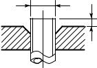
d) Flare Processing
Make certain that a clamp bar and copper pipe have been cleaned.
By means of the clamp bar, perform the flare processing correctly.
Use either a flare tool for R410A or conventional flare tool.
Flare processing dimensions differ according to the type of flare tool. When using a conventional flare tool, be sure to secure “dimension A” by using a gauge for size adjustment.
Fig. 3-2-1 Flare processing dimensions
Table 3-2-3 Dimensions related to flare processing for R410A
|
Outer |
A (mm) |
||||||
|
Nominal |
Thickness |
||||||
|
diameter |
Flare tool for R410A |
Conventional flare tool |
|||||
|
diameter |
(mm) |
||||||
|
(mm) |
|||||||
|
clutch type |
Clutch type |
Wing nut type |
|||||
|
1/4 |
6.35 |
0.8 |
0 to 0.5 |
1.0 to 1.5 |
1.5 to 2.0 |
||
|
3/8 |
9.52 |
0.8 |
0 to 0.5 |
1.0 to 1.5 |
1.5 to 2.0 |
||
|
1/2 |
12.70 |
0.8 |
0 to 0.5 |
1.0 to 1.5 |
2.0 to 2.5 |
||
|
5/8 |
15.88 |
1.0 |
0 to 0.5 |
1.0 to 1.5 |
2.0 to 2.5 |
||
|
Table 3-2-4 Dimensions related to flare processing for R22 |
|||||||
|
Outer |
A (mm) |
||||||
|
Nominal |
Thickness |
||||||
|
diameter |
Flare tool for R22 |
Conventional flare tool |
|||||
|
diameter |
(mm) |
||||||
|
(mm) |
|||||||
|
clutch type |
Clutch type |
Wing nut type |
|||||
|
1/4 |
6.35 |
0.8 |
0 to 0.5 |
0.5 to 1.0 |
1.0 to 1.5 |
||
|
3/8 |
9.52 |
0.8 |
0 to 0.5 |
0.5 to 1.0 |
1.0 to 1.5 |
||
|
1/2 |
12.70 |
0.8 |
0 to 0.5 |
0.5 to 1.0 |
1.5 to 2.0 |
||
|
5/8 |
15.88 |
1.0 |
0 to 0.5 |
0.5 to 1.0 |
1.5 to 2.0 |
||
Table 3-2-5 Flare and flare nut dimensions for R410A
|
Nominal |
Outer diameter |
Thickness |
Dimension (mm) |
Flare nut width |
|||||
|
diameter |
(mm) |
(mm) |
A |
B |
C |
D |
(mm) |
||
|
1/4 |
6.35 |
0.8 |
9.1 |
9.2 |
6.5 |
13 |
17 |
||
|
3/8 |
9.52 |
0.8 |
13.2 |
13.5 |
9.7 |
20 |
22 |
||
|
1/2 |
12.70 |
0.8 |
16.6 |
16.0 |
12.9 |
23 |
26 |
||
|
5/8 |
15.88 |
1.0 |
19.7 |
19.0 |
16.0 |
25 |
29 |
||
– 10 –
![]()
Table 3-2-6 Flare and flare nut dimensions for R22
|
Nominal |
Outer diameter |
Thickness |
Dimension (mm) |
Flare nut width |
||||||||||||||||||||||||||
|
diameter |
(mm) |
(mm) |
A |
B |
C |
D |
(mm) |
|||||||||||||||||||||||
|
1/4 |
6.35 |
0.8 |
9.0 |
9.2 |
6.5 |
13 |
17 |
|||||||||||||||||||||||
|
3/8 |
9.52 |
0.8 |
13.0 |
13.5 |
9.7 |
20 |
22 |
|||||||||||||||||||||||
|
1/2 |
12.70 |
0.8 |
16.2 |
16.0 |
12.9 |
20 |
24 |
|||||||||||||||||||||||
|
5/8 |
15.88 |
1.0 |
19.7 |
19.0 |
16.0 |
23 |
27 |
|||||||||||||||||||||||
|
3/4 |
19.05 |
1.0 |
23.3 |
24.0 |
19.2 |
34 |
36 |
|||||||||||||||||||||||
|
to |
46˚ |
|||||||||||||||||||||||||||||
|
45˚ |
||||||||||||||||||||||||||||||
|
B |
A |
C |
D |
|||||||||||||||||||||||||||
|
43˚ |
to |
||||||
|
45˚ |
Fig. 3-2-2 Relations between flare nut and flare seal surface
2.Flare Connecting Procedures and Precautions
a)Make sure that the flare and union portions do not have any scar or dust, etc.
b)Correctly align the processed flare surface with the union axis.
c)Tighten the flare with designated torque by means of a torque wrench. The tightening torque for R410A is the same as that for conventional R22. Incidentally, when the torque is weak, the gas leakage may occur.
When it is strong, the flare nut may crack and may be made non-removable. When choosing the tightening torque, comply with values designated by manufacturers. Table 3-2-7 shows reference values.
NOTE :
When applying oil to the flare surface, be sure to use oil designated by the manufacturer.
If any other oil is used, the lubricating oils may deteriorate and cause the compressor to burn out.
Table 3-2-7 Tightening torque of flare for R410A [Reference values]
|
Nominal |
Outer diameter |
Tightening torque |
Tightening torque of torque |
|
|
wrenches available on the market |
||||
|
diameter |
(mm) |
N•m (kgf•cm) |
||
|
N•m (kgf•cm) |
||||
|
1/4 |
6.35 |
14 to 18 (140 to 180) |
16 (160), 18 (180) |
|
|
3/8 |
9.52 |
33 to 42 (330 to 420) |
42 (420) |
|
|
1/2 |
12.70 |
50 to 62 (500 to 620) |
55 (550) |
|
|
5/8 |
15.88 |
63 to 77 (630 to 770) |
65 (650) |
|
– 11 –

3-3. Tools
3-3-1. Required Tools
The service port diameter of packed valve of the outdoor unit in the air-water heat pump using R410A is changed to prevent mixing of other refrigerant. To reinforce the pressure-resisting strength, flare processing dimensions and opposite side dimension of flare nut (For Ø12.7 copper pipe) of the refrigerant piping are lengthened.
The used refrigerating oil is changed, and mixing of oil may cause a trouble such as generation of sludge, clogging of capillary, etc. Accordingly, the tools to be used are classified into the following three types.
1.Tools exclusive for R410A (Those which cannot be used for conventional refrigerant (R22))
2.Tools exclusive for R410A, but can be also used for conventional refrigerant (R22)
3.Tools commonly used for R410A and for conventional refrigerant (R22)
The table below shows the tools exclusive for R410A and their interchangeability.
Tools exclusive for R410A (The following tools for R410A are required.)
Tools whose specifications are changed for R410A and their interchangeability
|
R410A |
Conventional air-water |
|||||
|
air-water heat pump installation |
heat pump installation |
|||||
|
No. |
Used tool |
Usage |
||||
|
Existence of |
Whether conven- |
Whether new equipment |
||||
|
new equipment |
tional equipment |
can be used with |
||||
|
for R410A |
can be used |
conventional refrigerant |
||||
|
1 |
Flare tool |
Pipe flaring |
Yes |
*(Note 1) |
¡ |
|
|
Copper pipe gauge for |
Flaring by |
*(Note 1) |
*(Note 1) |
|||
|
2 |
adjusting projection |
Yes |
||||
|
conventional flare tool |
||||||
|
margin |
||||||
|
3 |
Torque wrench |
Connection of flare nut |
Yes |
× |
× |
|
|
(For Ø12.7) |
||||||
|
4 |
Gauge manifold |
Evacuating, refrigerant |
Yes |
× |
× |
|
|
5 |
Charge hose |
charge, run check, etc. |
||||
|
6 |
Vacuum pump adapter |
Vacuum evacuating |
Yes |
× |
¡ |
|
|
7 |
Electronic balance for |
Refrigerant charge |
Yes |
× |
¡ |
|
|
refrigerant charging |
||||||
|
8 |
Refrigerant cylinder |
Refrigerant charge |
Yes |
× |
× |
|
|
9 |
Leakage detector |
Gas leakage check |
Yes |
× |
¡ |
|
|
10 |
Charging cylinder |
Refrigerant charge |
(Note 2) |
× |
× |
(Note 1) When flaring is carried out for R410A using the conventional flare tools, adjustment of projection margin is necessary. For this adjustment, a copper pipe gauge, etc. are necessary.
(Note 2) Charging cylinder for R410A is being currently developed.
General tools (Conventional tools can be used.)
In addition to the above exclusive tools, the following equipments which serve also for R22 are necessary as the general tools.
1.Vacuum pump
Use vacuum pump by attaching vacuum pump adapter.
2.Torque wrench (For Ø6.35, Ø9.52)
3.Pipe cutter
|
4. |
Reamer |
9. |
Hole core drill (Ø65) |
|
5. |
Pipe bender |
10. |
Hexagon wrench |
|
6. |
Level vial |
(Opposite side 4mm) |
|
|
7. |
Screwdriver (+, –) |
11. |
Tape measure |
|
8. |
Spanner or Monkey wrench |
12. |
Metal saw |
Also prepare the following equipments for other installation method and run check.
|
1. |
Clamp meter |
3. |
Insulation resistance tester |
|
2. |
Thermometer |
4. |
Electroscope |
– 12 –
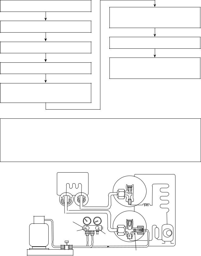
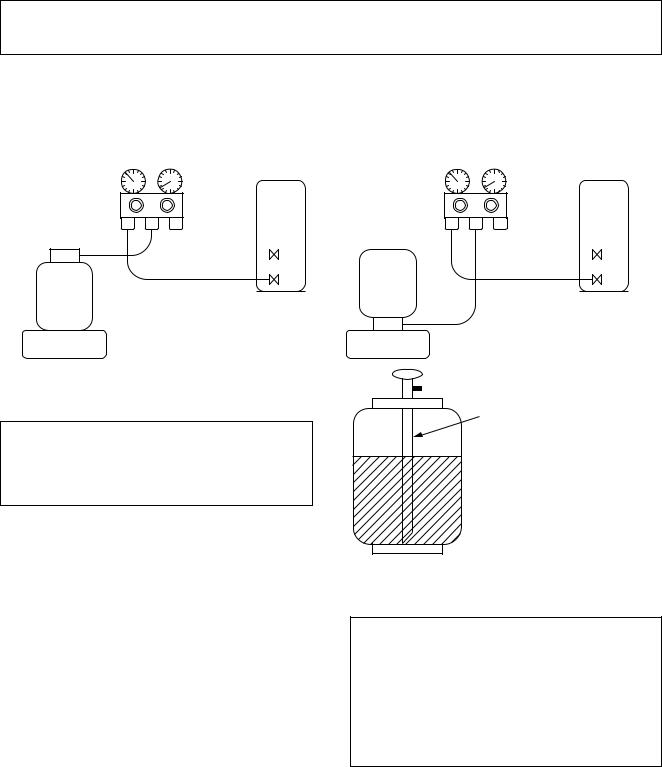
3-4. Recharging of Refrigerant
When it is necessary to recharge refrigerant, charge the specified amount of new refrigerant according to the following steps.
Recover the refrigerant, and check no refrigerant remains in the equipment.
Connect the charge hose to packed valve service port at the outdoor unit’s gas side.
Connect the charge hose to the vacuum pump adapter.
Open fully both packed valves at liquid and gas sides.
Place the handle of the gauge manifold Low in the fully opened position, and turn on the vacuum pump’s power switch. Then, evacuating the refrigerant in the cycle.
When the compound gauge’s pointer has indicated –0.1 Mpa (–76 cmHg), place the handle Low in the fully closed position, and turn off the vacuum pump’s power switch.
Keep the status as it is for 1 to 2 minutes, and ensure that the compound gauge’s pointer does not return.
Set the refrigerant cylinder to the electronic balance, connect the connecting hose to the cylinder and the connecting port of the electronic balance, and charge liquid refrigerant.
(For refrigerant charging, see the figure below.)
1.Never charge refrigerant exceeding the specified amount.
2.If the specified amount of refrigerant cannot be charged, charge refrigerant bit by bit in COOL mode.
3.Do not carry out additional charging.
When additional charging is carried out if refrigerant leaks, the refrigerant composition changes in the refrigeration cycle, that is characteristics of the air conditioner changes, refrigerant exceeding the specified amount is charged, and working pressure in the refrigeration cycle becomes abnormally high pressure, and may cause a rupture or personal injury.
(Water heat
(Outdoor unit)
exchanger unit)
|
Opened |
||
|
Refrigerant cylinder |
||
|
(with siphon) |
||
|
Check valve |
Opened |
|
|
Opened |
||
|
Open/close |
Closed |
|
|
valve for charging |
||
|
Service port |
||
|
Electronic balance for refrigerant charging |
Fig. 3-4-1 Configuration of refrigerant charging
– 13 –
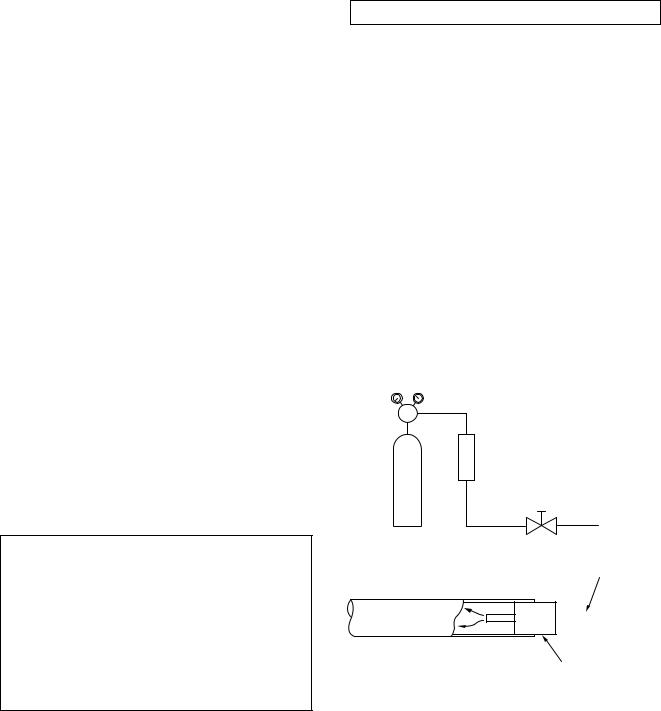
1.Be sure to make setting so that liquid can be charged.
2.When using a cylinder equipped with a siphon, liquid can be charged without turning it upside down.
It is necessary for charging refrigerant under condition of liquid because R410A is mixed type of refrigerant. Accordingly, when charging refrigerant from the refrigerant cylinder to the equipment, charge it turning the cylinder upside down if cylinder is not equipped with siphon.
|
[ Cylinder with siphon ] |
[ Cylinder without siphon ] |
|
Gauge manifold |
Gauge manifold |
|
OUTDOOR unit |
OUTDOOR unit |
Refrigerant
cylinder
Electronic
balance
R410A refrigerant is HFC mixed refrigerant. Therefore, if it is charged with gas, the composition of the charged refrigerant changes and the characteristics of the equipment varies.
cylinder Refrigerant
Electronic
balance
Siphon
Fig. 3-4-2
3-5. Brazing of Pipes
3-5-1. Materials for Brazing
1.Silver brazing filler
Silver brazing filler is an alloy mainly composed of silver and copper. It is used to join iron, copper or copper alloy, and is relatively expensive though it excels in solderability.
2.Phosphor bronze brazing filler
Phosphor bronze brazing filler is generally used to join copper or copper alloy.
3.Low temperature brazing filler
Low temperature brazing filler is generally called solder, and is an alloy of tin and lead. Since it is weak in adhesive strength, do not use it for refrigerant pipes.
1.Phosphor bronze brazing filler tends to react with sulfur and produce a fragile compound water solution, which may cause a gas leakage. Therefore, use any other type of brazing filler at a hot spring resort, etc., and coat the surface with a paint.
2.When performing brazing again at time of servicing, use the same type of brazing filler.
3-5-2. Flux
1.Reason why flux is necessary
•By removing the oxide film and any foreign matter on the metal surface, it assists the flow of brazing filler.
•In the brazing process, it prevents the metal surface from being oxidized.
•By reducing the brazing filler’s surface tension, the brazing filler adheres better to the treated metal.
– 14 –
2.Characteristics required for flux
•Activated temperature of flux coincides with the brazing temperature.
•Due to a wide effective temperature range, flux is hard to carbonize.
•It is easy to remove slag after brazing.
•The corrosive action to the treated metal and brazing filler is minimum.
•It excels in coating performance and is harmless to the human body.
As the flux works in a complicated manner as described above, it is necessary to select an adequate type of flux according to the type and shape of treated metal, type of brazing filler and brazing method, etc.
3.Types of flux
•Noncorrosive flux
Generally, it is a compound of borax and boric acid.
It is effective in case where the brazing temperature is higher than 800°C.
•Activated flux
Most of fluxes generally used for silver brazing are this type.
It features an increased oxide film removing capability due to the addition of compounds such as potassium fluoride, potassium chloride and sodium fluoride to the borax-boric acid compound.
4.Piping materials for brazing and used brazing filler/flux
|
Piping material |
Used brazing filler |
Used flux |
|
Copper — Copper |
Phosphor copper |
Do not use |
|
Copper — Iron |
Silver |
Paste flux |
|
Iron — Iron |
Silver |
Vapor flux |
1.Do not enter flux into the refrigeration cycle.
2.When chlorine contained in the flux remains within the pipe, the lubricating oil deteriorates. Therefore, use a flux which does not contain chlorine.
3.When adding water to the flux, use water which does not contain chlorine (e.g. distilled water or ion-exchange water).
4.Remove the flux after brazing.
3-5-3. Brazing
As brazing work requires sophisticated techniques, experiences based upon a theoretical knowledge, it must be performed by a person qualified.
In order to prevent the oxide film from occurring in the pipe interior during brazing, it is effective to proceed with brazing while letting dry Nitrogen gas (N2) flow.
Never use gas other than Nitrogen gas.
1.Brazing method to prevent oxidation
1)Attach a reducing valve and a flow-meter to the Nitrogen gas cylinder.
2)Use a copper pipe to direct the piping material, and attach a flow-meter to the cylinder.
3)Apply a seal onto the clearance between the piping material and inserted copper pipe for Nitrogen in order to prevent backflow of the Nitrogen gas.
4)When the Nitrogen gas is flowing, be sure to keep the piping end open.
5)Adjust the flow rate of Nitrogen gas so that it is lower than 0.05 m3/Hr or 0.02 MPa (0.2kgf/cm2) by means of the reducing valve.
6)After performing the steps above, keep the Nitrogen gas flowing until the pipe cools down to a certain extent (temperature at which pipes are touchable with hands).
7)Remove the flux completely after brazing.
M Flow meter
Stop valve
Nitrogen gas cylinder
From Nitrogen cylinder
Pipe 

 Nitrogen gas
Rubber plug
Fig. 3-5-1 Prevention of oxidation during brazing
– 15 –
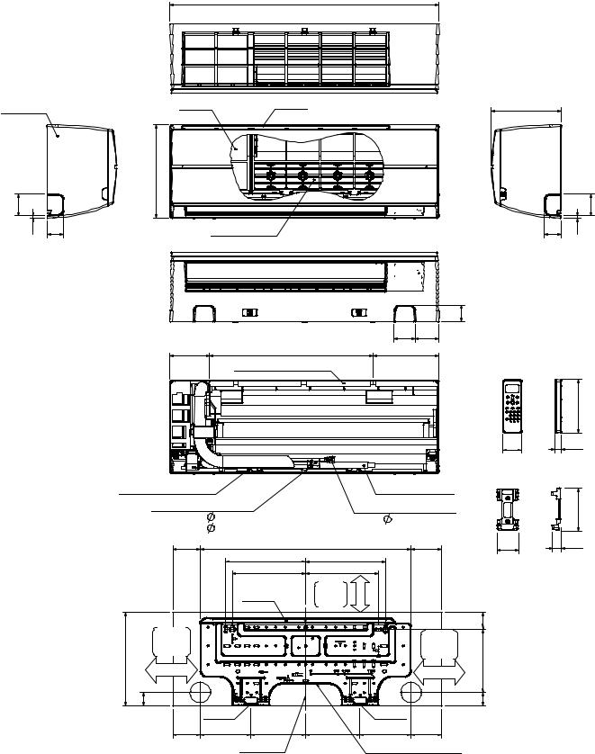
4. CONSTRUCTION VIEWS
RAS-M07SKV-E, RAS-M10SKV-E, RAS-M13SKV-E, RAS-M16SKV-E RAS-M10SKCV-E, RAS-M13SKCV-E, RAS-M16SKCV-E
790
|
Front panel |
Air filter |
Air inlet |
|||
|
275 |
||
|
63 |
||
|
7 |
48 |
Heat exchanger |
|
Knock out system |
Knock out system |
49
62 69
|
116 |
480 |
193 |
|
Installation plate hanger |
157
56 19 Wireless remote controller
|
Installation plate hanger |
Drain hose (0.50m) |
|||||||
|
Connecting pipe (0.35m) |
Connecting pipe (0.40m) |
125 |
||||||
|
(For 07,10,13 series; Flare |
9.52mm) |
(Flare |
6.35mm) |
|||||
|
(For 16 series; Flare |
12.7mm) |
26 |
||||||
|
84.5 |
235 |
621 |
84.5 |
63 |
||||
|
235 |
Remote controller holder |
|||||||
|
215 |
215 |
|||||||
|
Minimum |
more |
|||||||
|
Hanger |
distance |
|||||||
|
65 or |
||||||||
|
to ceiling |
||||||||
|
Minimum |
45 |
|||||||
|
Minimum |
||||||||
|
distance |
||||||||
|
distance |
||||||||
|
to wall |
||||||||
|
275 |
to wall |
190 |
||||||
|
170 or more |
170 or more |
|||||||
|
40 |
40 |
|||||||
|
Hanger |
Hanger |
|||||||
|
84.5 |
150 |
160.5 |
160.5 |
150 |
84.5 |
|||
|
Center line |
Installation plate outline |
– 16 –

Revised-2
5. WIRING DIAGRAM
5-1. RAS-M07SKV-E, RAS-M10SKV-E, RAS-M13SKV-E,
RAS-M10SKCV-E, RAS-M13SKCV-E
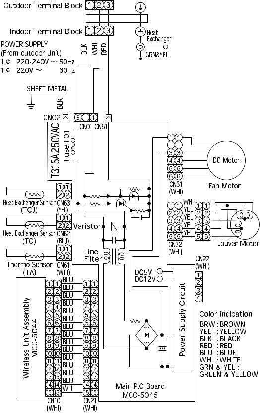
Revised-2
5-2. RAS-M16SKV-E
RAS-M16SKCV-E
– 18 –
Revised-2
6. SPECIFICATIONS OF ELECTRICAL PARTS
Indoor Unit
|
No. |
Parts name |
Type |
Specifications |
|
|
Fan motor |
M07SKV-E, M10SKV-E, |
AFS-220-20-4AR |
AC240V, 20W |
|
|
1 |
M13SKV-E, M10SKCV-E, |
|||
|
(for indoor) |
M13SKCV-E |
|||
|
M16SKV-E, M16SKCV-E |
ICF-340-30-2B |
DC 340V, 30W |
||
|
2 |
Room temp. sensor (TA-sensor) |
( − ) |
10kΩ at 25°C |
|
|
3 |
Heat exchanger temp. sensor (TC-sensor) |
( − ) |
10kΩ at 25°C |
|
|
4 |
Louver motor |
MP24Z3T |
Output (Rated) 1W, 16 poles, DC12V |
– 19 –
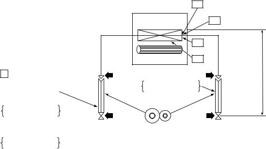
Revised-2
7. REFRIGERANT CYCLE DIAGRAM
P Pressure measurement
Gauge attaching port
Vacuum pump connecting port
Deoxidized copper pipe Outer dia. : 9.52mm Thickness : 0.8mm
|
INDOOR UNIT |
T1 |
Temp. measurement |
|||||
|
Indoor heat |
TCJ |
||||||
|
exchanger |
|||||||
|
TC |
heightAllowable |
10m:difference |
lengthpipeAllowable |
||||
|
Cross flow fan |
TA |
Max. |
: 1 |
||||
|
Min. |
: 1 |
||||||
|
Deoxidized copper pipe |
Chargeless : 1 |
||||||
|
Outer dia. : 6.35mm |
Charge : 1 |
||||||
|
Thickness : 0.8mm |
|||||||
|
Sectional shape |
|||||||
|
of heat insulator |
M16SKV-E, M16SKCV-E
Deoxidized copper pipe
Outer dia. : 12.7mm
Thickness : 0.8mm
1 : Refer to the service manual of multi outdoor unit to be combined.
– 20 –
![]()
Revised-2
8. CONTROL BLOCK DIAGRAM
8-1. Indoor Unit
RAS-M07SKV-E, RAS-M10SKV-E, RAS-M13SKV-E, RAS-M16SKV-E
|
Heat Exchanger Sensor (Tcj) |
M.C.U. |
Indoor Unit Control Unit |
|||
|
Functions |
Louver |
||||
|
Heat Exchanger Sensor (Tc) |
Motor |
||||
|
Room Temperature Sensor (Ta) |
• Cold draft preventing Function |
||||
|
• 3-minute Delay at Restart for Compressor |
Louver Motor |
||||
|
Drive Control |
|||||
|
Infrared Rays Signal Receiver |
|||||
|
• Fan Motor Starting Control |
|||||
|
and Indication |
Indoor Fan |
||||
|
• Processing |
Motor Control |
||||
|
Initializing Circuit |
(Temperature Processing) |
||||
|
Clock Frequency |
• Timer |
Indoor |
|||
|
Fan Motor |
|||||
|
Oscillator Circuit |
• Serial Signal Communication |
||||
|
• Clean Function |
|||||
|
Power Supply |
|||||
|
Circuit |
Converter (D.C circuit)
|
Noise Filter |
Serial Signal Transmitter/Receiver |
||
|
From Outdoor Unit |
|||
|
220-240V ~50Hz |
Serial Signal Communication |
||
|
220V ~60Hz |
(Operation Command and Information) |
|
Remote Controller |
Infrared Rays, 36.7kHz |
REMOTE CONTROLLER
Operation (START/STOP)
Operation Mode Selection
AUTO, COOL, DRY, HEAT
Thermo. Setting
Fan Speed Selection
ON TIMER Setting
OFF TIMER Setting
Louver AUTO Swing
Louver Direction Setting
ECO
Hi-POWER
COMFORT SLEEP
QUIET
– 21 –
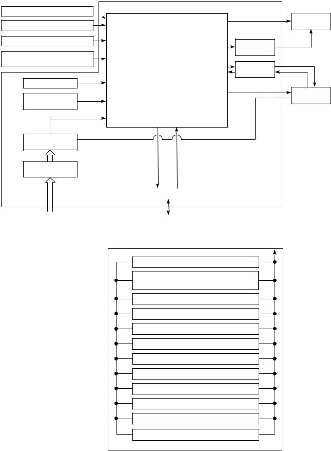
|
RAS-M10SKCV-E, RAS-M13SKCV-E, RAS-M16SKCV-E |
||||
|
Heat Exchanger Sensor (Tcj) |
M.C.U. |
Indoor Unit Control Unit |
||
|
Louver |
||||
|
Functions |
||||
|
Heat Exchanger Sensor (Tc) |
Motor |
|||
|
Room Temperature Sensor (Ta) |
• Cold draft preventing Function |
|||
|
• 3-minute Delay at Restart for Compressor |
Louver Motor |
|||
|
Drive Control |
||||
|
Infrared Rays Signal Receiver |
||||
|
• Fan Motor Starting Control |
||||
|
and Indication |
Indoor Fan |
|||
|
• Processing |
Motor Control |
|||
|
Initializing Circuit |
(Temperature Processing) |
|||
|
Clock Frequency |
• Timer |
Indoor |
||
|
Fan Motor |
||||
|
Oscillator Circuit |
• Serial Signal Communication |
|||
|
• Clean Function |
||||
|
Power Supply |
||||
|
Circuit |
Converter (D.C circuit)
|
Noise Filter |
Serial Signal Transmitter/Receiver |
||
|
From Outdoor Unit |
|||
|
220-240V ~50Hz |
Serial Signal Communication |
||
|
220V ~60Hz |
(Operation Command and Information) |
|
Remote Controller |
Infrared Rays, 36.7kHz |
REMOTE CONTROLLER
Operation (START/STOP)
Operation Mode Selection
AUTO, COOL, DRY, Fan only
Thermo. Setting
Fan Speed Selection
ON TIMER Setting
OFF TIMER Setting
Louver AUTO Swing
Louver Direction Setting
ECO
Hi-POWER
COMFORT SLEEP
QUIET
– 22 −

9. OPERATION DESCRIPTION
9-1. Outline of Air Conditioner Control
This air conditioner is a capacity-variable type air conditioner, which uses AC or DC motor for the indoor for motor and the outdoor fan motor. And the capacityproportional control compressor mounted. The DC motor drive circuit is mounted to the indoor unit.
The compressor and the inverter to control fan motor are mounted to the outdoor unit.
The entire air conditioner is mainly controlled by the indoor unit controller.
The indoor unit controller drives the indoor fan motor based upon command sent from the remote controller, and transfers the operation command to the outdoor unit controller.
The outdoor unit controller receives operation command from the indoor unit side, and controls the outdoor fan and the pulse motor valve. (P.M.V) Besides, detecting revolution position of the compressor motor, the outdoor unit controller controls speed of the compressor motor by controlling output voltage of the inverter and switching timing of the supply power (current transfer timing) so that motors drive according to the operation command.
And then, the outdoor unit controller transfers reversely the operating status information of the outdoor unit to control the indoor unit controller.
As the compressor adopts four-pole brushless DC motor, the frequency of the supply power from inverter to compressor is two-times cycles of the actual number of revolution.
1.Role of indoor unit controller
The indoor unit controller judges the operation commands from the remote controller and assumes the following functions.
•Judgment of suction air temperature of the indoor heat exchanger by using the indoor temp. sensor. (TA sensor)
•Judgment of the indoor heat exchanger temperature by using heat exchanger sensor (TC sensor) (Prevent-freezing control, etc.)
•Louver motor control
•Indoor fan motor operation control
•LED (Light Emitting Diode) display control
•Transferring of operation command signal (Serial signal) to the outdoor unit
•Reception of information of operation status (Serial signal including outside temp. data) to the outdoor unit and judgment/display of error
2.Role of outdoor unit controller
•Detection of inverter input current and current release operation
•Over-current detection and prevention operation to IGBT module (Compressor stop function)
•Compressor and outdoor fan stop function when serial signal is off (when the serial signal does not reach the board assembly of outdoor control by trouble of the signal system)
•Transferring of operation information (Serial signal) from outdoor unit controller to indoor unit controller
•Detection of outdoor temperature and operation revolution control
•Defrost control in heating operation (Temp. measurement by outdoor heat exchanger and control for 4-way valve and outdoor fan)
3.Contents of operation command signal (Serial signal) from indoor unit controller to outdoor unit controller
The following three types of signals are sent from the indoor unit controller.
•Operation mode set on the remote controller
•Compressor revolution command signal defined by indoor temperature and set temperature (Correction along with variation of room temperature and correction of indoor heat exchanger temperature are added.)
•Temperature of indoor heat exchanger
•For these signals ([Operation mode] and [Compressor revolution] indoor heat exchanger temperature), the outdoor unit controller monitors the input current to the inverter, and performs the followed operation within the range that current does not exceed the allowable value.
4.Contents of operation command signal (Serial signal) from outdoor unit controller to indoor unit controller
The following signals are sent from the outdoor unit controller.
•The current operation mode
•The current compressor revolution
•Outdoor temperature
•Existence of protective circuit operation
For transferring of these signals, the indoor unit controller monitors the contents of signals, and judges existence of trouble occurrence.
Contents of judgment are described below.
•Whether distinction of the current operation status meets to the operation command signal
Receiving the operation command signal (Serial signal) from the indoor unit controller, the outdoor unit performs its role.
|
• |
Compressor operation control |
||
|
• |
Operation control of outdoor fan motor |
||
|
• |
P.M.V. control |
||
|
• |
4-way valve control (Heat Pump model only) |
•Whether protective circuit operates
When no signal is received from the outdoor unit controller, it is assumed as a trouble.
Operations followed to judgment of serial signal from indoor side.
− 23 −
|
9-2. |
Operation Description |
||
|
1. |
Basic operation …………………………………………………………………………………………….. |
25 |
|
|
1. Operation control ……………………………………………………………………………………… |
25 |
||
|
2. Operating mode selection when performing 2-room operation ……………………. |
26 |
||
|
3. Cooling/Heating operation …………………………………………………………………………. |
26 |
||
|
4. AUTO operation ………………………………………………………………………………………. |
27 |
||
|
5. DRY operation …………………………………………………………………………………………. |
27 |
||
|
2. |
Indoor fan motor control ………………………………………………………………………………… |
28 |
|
|
3. |
Capacity control ……………………………………………………………………………………………. |
30 |
|
|
4. |
Release protective control by temperature of indoor heat exchanger…………………… |
31 |
|
|
5. |
Louver control ………………………………………………………………………………………………. |
32 |
|
|
1) Louver position …………………………………………………………………………………………. |
32 |
||
|
2) Air direction adjustment …………………………………………………………………………….. |
32 |
||
|
3) Swing ……………………………………………………………………………………………………… |
32 |
||
|
6. |
ECO operation ……………………………………………………………………………………………… |
33 |
|
|
7. |
Temporary operation ……………………………………………………………………………………… |
34 |
|
|
8. |
Self-Cleaning function …………………………………………………………………………………… |
35 |
|
|
9. |
Selt-Cleaning function release ……………………………………………………………………….. |
36 |
|
|
10. |
Remote-A or B selection ……………………………………………………………………………….. |
37 |
|
|
11. |
QUIET mode ………………………………………………………………………………………………. |
38 |
|
|
12. |
COMFORT SLEEP mode …………………………………………………………………………….. |
38 |
|
|
13. |
Short Timer …………………………………………………………………………………………………. |
38 |
|
|
14. |
One-Touch Comfort …………………………………………………………………………………….. |
39 |
|
|
15. |
Hi-POWER Mode ………………………………………………………………………………………… |
39 |
|
|
16. |
FILTER Indicator ………………………………………………………………………………….. |
39 |
|
|
9-3. |
Auto Restart Function…………………………………………………………………………………… |
40 |
|
|
9-3-1. How to Set the Auto Restart Function ………………………… …………………………………. |
40 |
||
|
9-3-2. How to Cancel the Auto Restart Function ………………………………………………………. |
41 |
||
|
9-3-3. Power Failure During Timer Operation …………………………………………………………. |
41 |
||
|
9-4. Remote Controller and Its Fuctions ………………………………………………………….. |
42 |
||
|
9-4-1. Parts Name of Remote Controller ………………………………………………………………….. |
42 |
||
|
9-4-2. Operation of remote control ………………………………………………………………………….. |
42 |
||
|
9-4-3. Name and Functions of Indications on Remote Controller ………………………………… |
45 |
– 24 −
|
Item |
Operation flow and applicable data, etc. |
Description |
1. Basic 1. Operation control
operation
Receiving the user’s operation condition setup, the operation statuses of indoor/outdoor units are controlled.
1)The operation conditions are selected by the remote controller as shown in the below.
2)A signal is sent by ON button of the remote controller.
3)The signal is received by a sensor of the indoor unit and processed by the indoor controllers as shown in the below.
4)The indoor controller controls the indoor fan motor and louver motor.
5)The indoor controller sends the operation command to the outdoor controller, and sends/receives the control status with a serial signal.
6)The outdoor controller controls the operation as shown in the left, and also controls the compressor, outdoor fan motor, 4-way valve and pulse motor valve.
Remote controller
Selection of operation conditions
ON/OFF
Control contents of remote controller
•ON/OFF
•Operation select
•Temperature setup
•Air direction
•Swing
•Air volume select (AUTO/LOW/LOW+/MED/MED+/HIGH)
|
• ECO |
∙ COMFORT SLEEP |
|
• ON timer setup |
∙ QUIET |
|
• OFF timer setup |
∙ PRESET |
|
• Hi-POWER |
∙ ONE-TOUCH |
Indoor unit
|
Signal receiving |
Indoor unit control |
|||||
|
• Command signal generating function of |
||||||
|
Indoor unit control |
indoor unit operation |
• Indoor fan motor |
||||
|
• Calculation function (temperature calculation) |
||||||
|
• Louver motor |
||||||
|
• Activation compensation function of indoor fan |
||||||
|
Operation command |
||||||
|
• Cold draft preventive function |
||||||
|
• Timer function |
||||||
|
Serial signal send/receive |
• Indoor heat exchanger release control |
|||||
|
Outdoor unit |
~ |
||||||||||||
|
Serial signal send/receive |
Outdoor unit control |
Inverter |
|||||||||||
|
• Frequency control of inverter output |
|||||||||||||
|
Outdoor unit control |
• Waveform composite function |
||||||||||||
|
• Calculation function |
• Compressor |
||||||||||||
|
(Temperature calculation) |
• Outdoor fan motor |
||||||||||||
|
• AD conversion function |
|||||||||||||
|
• 4-way valve |
|||||||||||||
|
• Quick heating function |
• Pulse motor valve |
||||||||||||
|
• Delay function of compressor reactivation |
(P.M.V.) |
||||||||||||
|
• Current release function |
|||||||||||||
|
• GTr over-current preventive function |
|||||||||||||
|
• Defrost operation function |
|||||||||||||
– 25 –

|
Item |
Operation flow and applicable data, etc. |
Description |
|
1. Basic |
2. Operating mode selection when performing 2-room operation |
|
|
operation |
1) The outdoor unit operation mode conforms to the instructions of the indoor unit that was pressed first. |
2)When combined operation consisting of cooling (dry) and heating, fan and heating, or cleaning operation and heating is performed, operation conforms to the instructions of the indoor unit that was pressed first as shown in the following table.
3)The indoor fan stops for the indoor unit that was pressed last and which instructions are ignored.
4)When three or four indoor units are operated concurrently, the priority is also given to operating mode of the indoor unit which was pressed first as same as the case when two indoor units are operated concurrently.
|
No. |
Indoor unit |
Set operating mode |
Actual indoor unit operation |
Actual outdoor unit operation |
|
|
1 |
Pressed first |
Cooling (dry) |
Cooling (dry) |
Cooling |
|
|
Pressed last |
Cooling (dry) |
Cooling (dry) |
|||
|
2 |
Pressed first |
Heating |
Heating |
Heating |
|
|
Pressed last |
Heating |
Heating |
|||
|
3 |
Pressed first |
Fan only |
Fan only |
Stopped |
|
|
Pressed last |
Fan only |
Fan only |
|||
|
4 |
Pressed first |
Fan only |
Fan only |
Cooling |
|
|
Pressed last |
Cooling (dry) |
Cooling (dry) |
|||
|
5 |
Pressed first |
Cooling (dry) |
Cooling (dry) |
Cooling |
|
|
Pressed last |
Fan only |
Fan only |
|||
|
6 |
Pressed first |
Cooling (dry) |
Cooling (dry) |
Cooling |
|
|
Pressed last |
Heating |
Fan stopped |
|||
|
7 |
Pressed first |
Heating |
Heating |
Heating |
|
|
Pressed last |
Cooling (dry) |
Fan stopped |
|||
|
8 |
Pressed first |
Cleaning operation |
Cleaning operation |
Stopped |
|
|
Pressed last |
Cleaning operation |
Cleaning operation |
|||
|
9 |
Pressed first |
Cleaning operation |
Cleaning operation |
Cooling |
|
|
Pressed last |
Cooling (dry) |
Cooling (dry) |
|||
|
10 |
Pressed first |
Cooling (dry) |
Cooling (dry) |
Cooling |
|
|
Pressed last |
Cleaning operation |
Cleaning operation |
|||
|
11 |
Pressed first |
Cleaning operation |
Cleaning operation |
Stopped |
|
|
Pressed last |
Fan only |
Fan only |
|||
|
12 |
Pressed first |
Fan only |
Fan only |
Stopped |
|
|
Pressed last |
Cleaning operation |
Cleaning operation |
|||
|
13 |
Pressed first |
Cleaning operation |
Cleaning operation |
Stopped |
|
|
Pressed last |
Heating |
Fan stopped |
|||
|
14 |
Pressed first |
Heating |
Heating |
Heating |
|
|
Pressed last |
Cleaning operation |
Fan stopped |
|||
3. Cooling/Heating operation
The operations are performed in the following parts by controls according to cooling/heating conditions.
1)Receiving the operation ON signal of the remote controller, the cooling or heating operation signal starts being transferred from the indoor controller to the outdoor unit.
2)At the indoor unit side, the indoor fan is operated according to the contents of «2. Indoor fan motor contr «land the louver according to the contents of «9. Louver control«, respectively.
3)The outdoor unit controls the outdoor fan motor, compressor, pulse motor valve and 4-way valve according to the operation signal sent from the indoor unit.
*1. The power coupler of 4-way valve is usually turned off, and it is turned on during defrost operation. (Only in heating)
|
Operation On |
Setup of remote controller |
||
|
Indoor unit control |
Indoor fan motor control / Louver control |
||
Sending of operation command signal

 Compressor revolution control / Outdoor fan motor control / 4-way valve control Outdoor unit control
  [In cooling operation: OFF, In heating operation: ON]
Pulse motor valve control
– 26 –
 Loading…