
1
Для настройки Точки доступа используйте только проводное
соединение.
Адаптер питания можно также подключить напрямую к Точке
доступа. В этом случае вы можете подключить ваш компьютер
напрямую к Точке доступа с помощью кабеля Ethernet.
Отключите все сетевые
устройства, в том числе ваш
компьютер(ы), Адаптер
питания и Точку доступа.
С помощью кабеля Ethernet
подключите Ваш компьютер к
порту LAN, расположенному
на Адаптере питания.
Подсоедините поставляемый
в комплекте Блок питания к
разъему для питания на
Адаптере питания. Вилку
Блока питания подключите к
стандартной электрической
розетке.
С помощью кабеля Ethernet
подсоедините вашу Точку
доступа к порту PoE на
Адаптере питания.
Установка
1
Подключение Устройства
Внимание
Внимание
-
Contents
-
Table of Contents
-
Bookmarks
Quick Links
TL-WA5110G
54M High Power Wireless Access Point
I
Rev: 1.0.0
1910010154
Related Manuals for TP-Link TL-WA5110G
Summary of Contents for TP-Link TL-WA5110G
-
Page 1
TL-WA5110G 54M High Power Wireless Access Point Rev: 1.0.0 1910010154… -
Page 2
Specifications are subject to change without notice. is a registered trademark of TP-LINK TECHNOLOGIES CO., LTD. Other brands and product names are trademarks or registered trademarks of their respective holders. No part of the specifications may be reproduced in any form or by any means or used to make any derivative such as translation, transformation, or adaptation without permission from TP-LINK TECHNOLOGIES CO., LTD. -
Page 3: Fcc Statement
FCC STATEMENT This equipment has been tested and found to comply with the limits for a Class B digital device, pursuant to part 15 of the FCC Rules. These limits are designed to provide reasonable protection against harmful interference in a residential installation. This equipment generates, uses and can radiate radio frequency energy and, if not installed and used in accordance with the instructions, may cause harmful interference to radio communications.
-
Page 4
National Restrictions 2400.0-2483.5 MHz Country Restriction Bulgaria Outdoor use limited to 10 France mW e.i.r.p. within the band 2454-2483.5 MHz Italy Luxembourg None Norway Implemented Russian Federation Note: It’s not used outdoors in France. Reason/remark General authorization required for outdoor use and public service Military Radiolocation use. -
Page 5: Declaration Of Conformity
TP-LINK TECHNOLOGIES CO., LTD DECLARATION OF CONFORMITY For the following equipment: Product Description: 54 M High Power Wireless Access Point Model No.: TL-WA5110G Trademark: TP-LINK We declare under our own responsibility that the above products satisfy all the technical regulations applicable to the product within the scope of Council Directives:…
-
Page 6: Table Of Contents
Package Contents … 1 Chapter 1. Product Overview … 2 Overview of the Product… 2 Features… 2 Conventions … 3 Chapter 2. Hardware Installation … 4 2.1. The Front Panel … 4 2.2. The Rear Panel… 4 2.3. System Requirements… 5 2.4.
-
Page 7
4.7.3 Address Reservation … 34 Wireless settings… 35 Forwarding … 36 4.9.1 Virtual Servers… 36 4.9.2 Port Triggering… 38 4.9.3 DMZ … 39 4.9.4 UPnP… 40 4.10 Security… 41 4.10.1 Firewall … 41 4.10.2 IP Address Filtering … 42 4.10.3 Domain Filtering… -
Page 8
5.6.1 Basic Settings… 63 5.6.2 Wireless Mode… 64 5.6.3 Security Settings … 69 5.6.4 MAC Filtering… 71 5.6.5 Wireless Statistics … 74 5.6.6 Distance Setting … 74 5.6.7 Antenna Alignment … 75 5.6.8 Throughput Monitor … 76 DHCP… 76 5.7.1 DHCP Settings … 77 5.7.2 DHCP Clients List… -
Page 9: Package Contents
Package Contents The following items should be found in your package: One TL-WA5110G 54M High Power Wireless Access Point One AC power Adapter for TL-WA5110G 54M High Power Wireless Access Point One Power Injector Quick Installation Guide One Resource CD for TL-WA5110G 54M High Power Wireless Access Point, including:…
-
Page 10: Chapter 1. Product Overview
TKIP/AES encryption security. It also supports VPN pass-through for sensitive data secure transmission. The TL-WA5110G 54M High Power Wireless Access Point complies with the IEEE 802.11g and IEEE 802.11b standards so that the data transmission rate is up to 54Mbps. The wireless transmission range can extend up to tens of kilometers.
-
Page 11: Conventions
Supports Web management. 1.3 Conventions The AP or TL-WA5110G, or device mentioned in this User guide stands for TL-WA5110G 54M High Power Wireless Access Point without any explanations. Parameters provided in the pictures are just references for setting up the product, which may differ from the actual situation.
-
Page 12: Chapter 2. Hardware Installation
Chapter 2. Hardware Installation 2.1. The Front Panel The front panel of the TL-WA5110G consists of several LED indicators, which is designed to indicate connections. View from left to right. Table 2-1 describes the LEDs on the front panel of the router.
-
Page 13: System Requirements
Ensure the AP is powered on before it restarts completely. One LAN 10/100Mbps RJ45 port for connecting the AP to hub or switch AC power socket: only use the power adapter supplied with the TL-WA5110G 54Mbps Wireless Access Point, use of a different adapter may result in product damage.
-
Page 14
Adjust the direction of the antenna. Normally, upright is a good direction. Connect the Ethernet Broadband Router to the TL-WA5110G AP. Power on the AP. If you are connecting a desktop PC or laptop to your network, install the TP-LINK Wireless Adapter on the PC. -
Page 15: Chapter 3. Quick Installation Guide
The instructions in this section will help you configure each of your PCs to be able to communicate with the AP. The default IP address of the TL-WA5110G 54M High Power Wireless Access Point is 192.168.1.1. And the default Subnet Mask is 255.255.255.0. These values can be seen from the LAN.
-
Page 16: Quick Setup
The following instructions will guide you through a few easy steps to configure your AP and connect to Internet. With a Web-based (Internet Explorer or Netscape to configure and manage the TL-WA5110G 54M High Power Wireless Access Point. The Web-based utility can be used on any Windows, Macintosh or UNIX OS with a Web browser.
-
Page 17
Figure 3-4 Login Windows Note: If the above screen does not pop-up, it means that your Web-browser has been set to a proxy. Go to Tools menu>Internet Options>Connections>LAN Settings, in the screen that appears, cancel the Using Proxy checkbox, and click OK to finish it. If the User Name and Password are correct, you can configure the AP using the Web browser. -
Page 18
Note: The AP supports three mode operation modes for multi-user to access the Internet: AP client router, AP router and AP. In AP client router mode, it can access the Internet wirelessly by your WISP’s support. In AP router mode, it can access the Internet via ADSL/Cable Modem. In AP mode, it can access a wireless network by using WIFI. -
Page 19
Note: The IP parameters should have been provided by your ISP. IP Address — This is the WAN IP address as seen by external users on the Internet (including your ISP). Enter the IP address into the field. Subnet Mask — The Subnet Mask is used for the WAN IP address, it is usually 255.255.255.0 Default Gateway — Enter the gateway IP address into the box if required. -
Page 20
SSID — Enter a value of up to 32 characters. The same SSID must be assigned to all wireless devices on your network. The default SSID is TP-LINK. This value is case-sensitive. For example, TP-LINK is NOT the same as tp-link. -
Page 21: Chapter 4. Configuring The Device In Ap Client Router & Ap Router Operation Mode
Chapter 4. Configuring the Device in AP Client Router & AP Router Operation Mode This Chapter describes how to configure some advanced settings for your Access Point through the web-based management page. In the following explanations, we will take the device in AP Client Router operation mode for example.
-
Page 22
This field displays the current settings or information for the LAN, including the MAC address, IP address and Subnet Mask. Wireless This field displays basic information or status for wireless function, including Wireless Radio, SSID, Channel, Mode, Wireless MAC address, and IP address. These parameters apply to the WAN port of the router, including MAC address, IP address, Subnet Mask, Default Gateway and DNS server connection type, the Disconnect button will be shown here while you are accessing the… -
Page 23: Quick Setup
This field displays the router’s traffic statistics. System Up Time The total up time of the router since it was powered on or reset. 4.3 Quick Setup Please refer to Section 3.2: «Quick Setup.» 4.4 Operation Mode The AP supports three operation mode types, AP Client Router, AP Router and AP. Please select one your want.
-
Page 24: Wan
MAC Address — The physical address of the router, as seen from the LAN. The value can’t be changed. IP Address — Enter the IP address of your router in dotted-decimal notation (factory default: 192.168.1.1). Subnet Mask — An address code that determines the size of the network. Normally use 255.255.255.0 as the subnet mask.
-
Page 25
This page displays the WAN IP parameters assigned dynamically by your ISP, including IP address, Subnet Mask, Default Gateway, etc. Click Renew to renew the IP parameters from your ISP. Click Release to release the IP parameters. MTU Size — The normal MTU (Maximum Transmission Unit) value for most Ethernet networks is 1500 Bytes. -
Page 26
Figure 4-6 WAN — Static IP You should type the following parameters into the spaces provided: IP Address — Enter the IP address in dotted-decimal notation provided by your ISP. Subnet Mask — Enter the subnet Mask in dotted-decimal notation provided by your ISP, usually is 255.255.255.0. -
Page 27
User Name/Password — Enter the User Name and Password provided by your ISP. These fields are case-sensitive. Connect on Demand — You can configure the router to disconnect your Internet connection after a specified period of inactivity (Max Idle Time). If your Internet connection has been terminated due to inactivity, Connect on Demand enables the router to automatically re-establish your connection as soon as you attempt to access the Internet again. -
Page 28: Mac Clone
Caution: Sometimes the connection cannot be disconnected although you specify a time to Max Idle Time, since some applications are visiting the Internet continually in the background. Click the Connect button to connect immediately, Click the Disconnect button to disconnect immediately.
-
Page 29: Wireless
Some ISPs require that you register the MAC Address of your adapter, which is connected to your cable/DSL Modem or Ethernet during installation. Changes are rarely needed here. WAN MAC Address — This field displays the current MAC address of the WAN port, which is used for the WAN port.
-
Page 30: Wireless Mode
The default SSID is TP-LINK_xxxxxx (xxxxxx indicates the last six unique characters of each device’s MAC address). This value is case-sensitive. For example, TP-LINK is NOT the same as tp-link. Region-Select your region from the drop-down list. This filed specifies the region where the wireless function of the device can be used.
-
Page 31
Note: In AP Client Router, there is only Client mode available there is only Access Point mode available Access Point — Access Point mode allows wireless stations including AP clients to access the router. • Enable SSID Broadcast — If you select the Enable SSID Broadcast checkbox, the Wireless AP will broadcast its name (SSID) on the air. -
Page 32
• SSID — Enter the SSID of AP that you want to access. If you select the radio before SSID, the AP client will connect to AP according SSID. • MAC of AP — Enter the MAC address of AP that you want to access. If you select the radio before MAC of AP, the AP client will connect to AP according MAC address. -
Page 33: Security Settings
Figure 4-14 Wireless Mode settings in AP Router mode 4.6.3 Security Settings You can select one of the following security options:…
-
Page 34
Disable Security — The wireless security function can be enabled or disabled. If disabled, the wireless stations will be able to connect the device without encryption. It is recommended strongly that you choose one of following options to enable security. WEP — Select 802.11 WEP security. -
Page 35: Mac Filtering
1). For 64-bit encryption — You can enter 10 hexadecimal digits (any combination of 0-9, a-f, A-F, zero key is not permitted) or 5 ASCII characters. 2). For 128-bit encryption — You can enter 26 hexadecimal digits (any combination of 0-9, a-f, A-F, zero key is not permitted) or 13 ASCII characters.
-
Page 36
Figure 4-16 Wireless MAC address Filtering The Wireless MAC Address Filtering feature allows you to control wireless stations accessing the router, which depend on the station’s MAC addresses. MAC Address — The wireless station’s MAC address that you want to access. Status — The status of this entry either Enabled or Disabled. -
Page 37
Enter a simple description of the wireless station in the Description field. For example: Wireless station A. Privilege — Select the privileges for this entry, one of Allow / Deny / 64-bit / 128-bit / 152-bit. WEP Key — If you select 64-bit, 128-bit or 152-bit in the Privilege field, enter any combination of hexadecimal digits (0-9, a-f, A-F) in the specified length. -
Page 38: Wireless Statistics
Enabled in the Status pull-down list. Click the Save and the Return button. The filtering rules that configured should be similar to the following list: Note: 1) If you select the radio button Allow the stations not specified by any enabled entries in the list to access for Filtering Rules, the wireless station B will still not be able to access the router, however, other wireless stations that are not in the list will be able to access the router.
-
Page 39: Antenna Alignment
Use Default Setting: Keep the default setting if the AP is used for indoor environment. If you want to change the distance, please uncheck the Use Default Setting box. Distance: Specify the distance value in kilometers, accurate to the first decimal place. If the distance is set too short or too long, it will result poor connection and throughput performance, it is best to set the value at 110% of the real distance.
-
Page 40: Dhcp
Figure 4-21 Wireless Throughput Rate — The Throughput unit. Run Time — How long this function is running. Transmit- Wireless transmit rate information. Receive- Wireless receive rate information. Click the Start button to start wireless throughput monitor. Click the Stop button to stop wireless throughput monitor. 4.7 DHCP Figure 4-22 The DHCP menu There are three submenus under the DHCP menu (shown in Figure 4-22): DHCP Settings,…
-
Page 41: Dhcp Clients List
provides the TCP/IP configuration for all the PC(s) that are connected to the router on the LAN. The DHCP Server can be configured on the page (shown in Figure 4-23): DHCP Server — Enable or Disable the DHCP server. If you disable the Server, you must have another DHCP server within your network ,or else you have to manually configure the computer.
-
Page 42: Address Reservation
Index(ID)- The index of the DHCP Client Client Name — The name of the DHCP client MAC Address — The MAC address of the DHCP client Assigned IP — The IP address that the router has allocated to the DHCP client. Lease Time — The time of the DHCP client leased.
-
Page 43: Wireless Settings
Figure 4-26 Add or Modify an Address Reservation Entry To modify or delete an existing entry: Select a reserved address entry, Click the Modify in the entry if you want to modify it. If you want to delete the entry, click the Delete. Click the Save button.
-
Page 44: Forwarding
Disable short preamble — Disable short preamble and use long preamble only. 802.11b mode supports only long preamble and this parameter will be ignored. It is recommended that you do not change these settings. RTS threshold — RTS/CTS Threshold, the packet size that is used to determine if RTS/CTS should be sent.
-
Page 45
To setup a virtual server entry, please take the following steps: Click the Add New…in virtual servers page. (pop-up Figure 4-30) Select the service you want to use from the Common Service Port list. If the Common Service Port list does not have the service that you want to use, type the number of the service port or service port range in the Service Port box. -
Page 46: Port Triggering
4.9.2 Port Triggering Some applications require multiple connections, like Internet games, video conferencing, Internet calling and so on. These applications cannot work with a pure NAT router. Port Triggering is used for some of these applications that can work with a NAT router. You can set up Port Triggering on this page shown in Figure 4-31: Once configured, operation is as follows: 1.
-
Page 47: Dmz
Click the Save button to save the new rule. Figure 4-32 Add or Modify a Triggering Entry There are many popular applications in the Popular Application list. You can select one, and the application will fill in the Trigger Port, incoming Ports Range boxes automatically. And then, select the Enable option.
-
Page 48: Upnp
To assign a computer or server to be a DMZ server: Click the Enable radio button Enter the IP address of a local PC that is set to be DMZ host in the DMZ Host IP Address field Click the Save button. Note: After you set the DMZ host, the firewall related to the host will not work.
-
Page 49: Security
Click Disable to disable UPnP Click Refresh to update the Current UPnP Settings List. 4.10 Security Figure 4-35 The Security menu There are five submenus under the Security menu (shown in Figure 4-35): Firewall, IP Address Filtering, Domain Filtering, MAC Address Filtering and Advanced Security. Click any of them, and you will be able to configure the corresponding function.
-
Page 50: Ip Address Filtering
filtering rules for MAC Address Filtering: Allow or Deny the packets specified to pass through the router.. 4.10.2 IP Address Filtering The IP address Filtering feature allows you to control the Internet Access by specific users on your LAN based on their IP addresses. The IP address filtering is set on this page, Figure 4-37: To disable the IP Address Filtering feature, keep the default setting, Disabled.
-
Page 51: Domain Filtering
4. WAN IP Address — Enter a WAN IP Address or a range of WAN IP Addresses in the field, in dotted-decimal notation format. For example, 61.145.238.6 — 61.145.238.47. Keep the field blank, which means all WAN IP Addresses have been put into the field. 5.
-
Page 52: Add/Modify Domain Filtering Entry
Before adding a Domain Filtering entry, you must ensure that Enable Firewall and Enable Domain Filtering have been selected on the Firewall page. To Add a Domain filtering entry, click the Add New… button. The page «Add or Modify a Domain Filtering entry» will appear, shown in Figure 4-40: Figure 4-40 Add or Modify a Domain Filtering entry To add or modify a Domain Filtering entry, follow these instructions:…
-
Page 53: Mac Address Filtering
page. For example, if you want to block the PC(s) on your LAN to access websites www.xxyy.com.cn, www.aabbcc.com and websites with .net in the end on the Internet while no limit for other websites, you should specify the following Domain filtering list: 4.10.4 MAC Address Filtering Like the IP Address Filtering page, the MAC Address Filtering page (shown in Figure 4-41) allows you to control access to the Internet by users on your local network based on their MAC Address.
-
Page 54: Advanced Security
Click the Save button to save this entry. To add additional entries, repeat steps 1-4. When finished, click the Return button to return to the MAC Address Filtering page. To modify or delete an existing entry: Click the Modify in the entry you want to modify. If you want to delete the entry, click the Delete.
-
Page 55
Figure 4-43 Advanced Security settings Packets Statistic interval (5 ~ 60) — The default value is 10. Select a value between 5 and 60 seconds from the pull-down list. The Packets Statistic interval value indicates the time section of the packets statistic. The result of the statistic used for analysis by SYN Flood, UDP Flood and ICMP-Flood. -
Page 56: Static Routing
the router from the LAN port. The default value is disabled. If enabled, the ping packet from the LAN port cannot access the router. (Defends against some viruses) Click the Save button to save the settings. Click the Blocked DoS Host Table button to display the DoS host table by blocking. The page will appear that shown in Figure 4-44: This page shows Host IP Address and Host MAC Address for each host blocked by the router.
-
Page 57: Dynamic Dns
Select Enabled or Disabled for this entry from the Status pull-down list. Click the Save button to save the changes. Figure 4-46 Add or Modify a Static Route Entry To modify or delete an existing entry: Click the Modify in the entry you want to modify. If you want to delete the entry, click the Delete.
-
Page 58: Oray.net Ddns
Figure 4-47 Dyndns.org DDNS Settings To set up for DDNS, follow these instructions: Enter the User Name for your DDNS account. Enter the Password for your DDNS account. Enter the Domain Name you received from dynamic DNS service provider Click the Login button to log in to the DDNS service. Connection Status -The status of the DDNS service connection is displayed here.
-
Page 59: Comexe.cn Ddns
To set up for DDNS, follow these instructions: Enter the User Name for your DDNS account. Enter the Password for your DDNS account. Click the Login button to log in to the DDNS service. Connection Status — The status of the DDNS service connection is displayed here. Domain Name — The domain names are displayed here.
-
Page 60: System Tools
4.13 System Tools Figure 4-50 The System Tools menu There are eleven submenus under the System Tools menu (shown in Figure 4-50): Time, Firmware, Factory Defaults, Backup & Restore, Ping Watch Dog, Speed Test, Reboot, Password, Syslog, Remote Management and Statistics. Click any of them, and you will be able to configure the corresponding function.
-
Page 61: Firmware
To upgrade the router’s firmware, follow these instructions: Download the latest firmware upgrade file from the TP-LINK website Click Browse to view the folders and select the downloaded file.
-
Page 62: Factory Defaults
4.13.3 Factory Defaults This page (shown in Figure 4-53) allows you to restore the factory default settings for the router. Click the Restore button to reset all configuration settings to their default values. • The default User Name: admin • The default Password: admin •…
-
Page 63: Speed Test
It should be used for the preliminary throughput estimation between two network devices. The estimation is rough. You can input the remote device’s administrator Username and Password under Advance options to get a precise estimation if the remote device is TL-WA5110G too. Figure 4-55 Ping Watch Dog Utility…
-
Page 64: Reboot
Destination IP: The Remote device’s IP address. Advanced options: This is switch to show advanced test options which are used only for precise estimation. User: Administrator password of the remote device. It should be filled correctly if you want to get a precise estimation.
-
Page 65: Password
Click the Reboot button to reboot the router. Some settings of the router will take effect only after rebooting, which include: • Change LAN IP Address. (System will reboot automatically) • MAC Clone (system will reboot automatically) • DHCP service function. •…
-
Page 66: Remote Management
The router can keep logs of all traffic. You can query the logs to find what happened to the router. Click the Refresh button to refresh the logs. Click the Clear Log button to clear all the logs. 4.13.10 Remote Management You can configure the Remote Management function on this page shown in Figure 4-60.
-
Page 67: Statistics
Note: Be sure to change the router’s default password to a very secure password. In AP mode, port 80 is only supported. The web management port number will be set to 80 when the operation mode changes to AP mode. 4.13.11 Statistics The Statistics page (shown in Figure 4-61) displays the network traffic of each PC on the LAN, including total traffic and traffic of the last Packets Statistic interval seconds.
-
Page 68
The total amount of the TCP SYN packets transmitted to WAN in the last Packets Statistic interval seconds. Click the Save button to save the Packets Statistic interval value. Click the Auto-refresh checkbox to refresh automatically. Click the Refresh button to refresh immediately. -
Page 69: Chapter 5. Configuring The Device In Ap Operation Mode
Chapter 5. Configuring the Device in AP Operation Mode This Chapter describes how to configure some advanced settings for your Access Point through the web-based management page in AP operation mode. 5.1 Login After your successful login, you can configure and manage the Access Point. There are eight main menus on the left of the Web-based management page.
-
Page 70: Quick Setup
Operating Mode, Signal, SSID, Channel, Mode, MAC Address and IP Address. Traffic Statistics — This field displays the AP’s traffic statistics. System Up Time — The time of the AP running from it’s powered on or 5.3 Quick Setup Please refer to Section 3.2: «Quick Setup.»…
-
Page 71: Wireless
255.255.255.0 as the subnet mask. Gateway — The gateway should be in the same subnet as your IP address. MAC Address — the physical address of the AP, as seen from the LAN. This value can’t be changed. Note: 1) If you change the IP Address, you must use the new IP Address to log in the AP.
-
Page 72: Wireless Mode
MAC address). This value is case-sensitive. For example, TP-LINK is NOT the same as tp-link. Region-Select your region from the drop-down list. This filed specifies the region where the wireless function of the device can be used. It may be illegal to use the wireless function of the device in a region other than one of those specified in this field.
-
Page 73
Note: AP provides five operational modes: Access Point, Client, Repeater, Bridge (point to point), Bridge (point to Multi-point). Access Point — Access Point mode allows wireless stations including AP clients to access the router.. • Enable SSID Broadcast — If you select the Enable SSID Broadcast checkbox, the Wireless AP will broadcast its name (SSID) on the air. -
Page 74
Repeater mode to associate with the AP. Here is an example of how to configure wireless repeater. Please do the following: Configure the Operating Mode of the TL-WA5110G High Power wireless Access Points. • Configure AP1 on LAN Segment 1 in Access Point mode. -
Page 75
Configure the TL-WA5110G (AP1) on LAN Segment 1 in Point-to-Point Bridge mode. Configure the TL-WA5110G (AP2) on LAN Segment 2 in Point-to-Point Bridge mode. AP1 must have AP2’s MAC address in its MAC Address field and AP2 must have AP1’s MAC address in its MAC Address field. -
Page 76
Configure the Operating Mode of the TL-WA5110G High Power wireless Access Points. • Because it is in the central location, configure TL-WA5110G (AP1) on LAN Segment 1 in Point-to-Multi-Point Bridge mode. The MAC addresses of AP2 and AP3 are required in AP1. -
Page 77: Security Settings
the wireless network with wireless antenna accessories. Note: To apply any settings you have altered on the page, please click the Save button, and wait the AP reboot automatically. Click Survey will show the site list of scanning result shown as Figure 5-10. BSSID -The BSSID of the AP, usually also the MAC address of the AP.
-
Page 78
Disable Security — The wireless security function can be enabled or disabled. If disabled, the wireless stations will be able to connect the device without encryption. It is recommended strongly that you choose one of following options to enable security. WEP — Select 802.11 WEP security. -
Page 79: Mac Filtering
1). For 64-bit encryption — You can enter 10 hexadecimal digits (any combination of 0-9, a-f, A-F, zero key is not permitted) or 5 ASCII characters. 2). For 128-bit encryption — You can enter 26 hexadecimal digits (any combination of 0-9, a-f, A-F, zero key is not permitted) or 13 ASCII characters.
-
Page 80
Figure 5-12 Wireless MAC address Filtering The Wireless MAC Address Filtering feature allows you to control wireless stations accessing the router, which depend on the station’s MAC addresses. MAC Address — The wireless station’s MAC address that you want to access. Status — The status of this entry either Enabled or Disabled. -
Page 81
Enter a simple description of the wireless station in the Description field. For example: Wireless station A. Privilege — Select the privileges for this entry, one of Allow / Deny / 64-bit / 128-bit / 152-bit. WEP Key — If you select 64-bit, 128-bit or 152-bit in the Privilege field, enter any combination of hexadecimal digits (0-9, a-f, A-F) in the specified length. -
Page 82: Wireless Statistics
Enabled in the Status pull-down list. Click the Save and the Return button. The filtering rules that configured should be similar to the following list: Note: 1) If you select the radio button Allow the stations not specified by any enabled entries in the list to access for Filtering Rules, the wireless station B will still not be able to access the router, however, other wireless stations that are not in the list will be able to access the router.
-
Page 83: Antenna Alignment
Use Default Setting: Keep the default setting if the AP is used for indoor environment. If you want to change the distance, please uncheck the Use Default Setting box. Distance: Specify the distance value in kilometers, accurate to the first decimal place. If the distance is set too short or too long, it will result poor connection and throughput performance, it is best to set the value at 110% of the real distance.
-
Page 84: Throughput Monitor
Throughput Monitor 5.6.8 This page allows you to view the wireless throughput information Figure 5-17 Wireless Throughput Rate — The Throughput unit. Run Time — How long this function is running. Transmit- Wireless transmit rate information. Receive- Wireless receive rate information. Click the Start button to start wireless throughput monitor.
-
Page 85: Dhcp Settings
5.7.1 DHCP Settings The router is set up by default as a DHCP (Dynamic Host Configuration Protocol) server, which provides the TCP/IP configuration for all the PC(s) that are connected to the router on the LAN. The DHCP Server can be configured on the page (shown in Figure 5-19): DHCP Server — Enable or Disable the DHCP server.
-
Page 86: Address Reservation
Index(ID)- The index of the DHCP Client Client Name — The name of the DHCP client MAC Address — The MAC address of the DHCP client Assigned IP — The IP address that the router has allocated to the DHCP client. Lease Time — The time of the DHCP client leased.
-
Page 87: Wireless Settings
Figure 5-22 Add or Modify an Address Reservation Entry To modify or delete an existing entry: Select a reserved address entry, Click the Modify in the entry if you want to modify it. If you want to delete the entry, click the Delete. Click the Save button.
-
Page 88: System Tools
Before upgrading the AP’s firmware,you should write down some of your customized settings to avoid losing important configuration settings of AP . To upgrade the AP’s firmware, please take the following steps: Figure 5-25 Firmware Upgrade www.tp-link.com and can be downloaded for free. There is…
-
Page 89: Factory Defaults
Download a more recent firmware upgrade file from the TP-LINK website (www.tp-link.com). Click Browse to view the folders and select the downloaded file. Click Upgrade. Firmware Version — Displays the current firmware version. Hardware Version — Displays the current hardware version. The upgrade file must accord with the current hardware version.
-
Page 90: Ping Watch Dog
To restore the AP’s configuration, please take the following steps: • Click Browse to find the location of configuration file which you want to restore. • Click Restore to update the configuration with the file whose path is the one you have input or selected in the blank.
-
Page 91
Username and Password under Advance options to get a precise estimation if the remote device is TL-WA5110G too. Destination IP: The Remote device’s IP address. Advanced options: This is switch to show advanced test options which are used only for precise estimation. -
Page 92: Reboot
5.9.6 Reboot This page allows you to reboot the AP on the screen below (Figure 5-30). Click Reboot to reboot the AP. Some settings of the AP will take effect only after rebooting, which include: • Change LAN IP Address. (System will reboot automatically) •…
-
Page 93: Syslog
Click Save when finished. Click Clear All to clear all. 5.9.8 Syslog This page allows you to query the Logs of the AP on the screen below Figure 5-32). Figure 5-32 System Log The AP can keep logs of all traffic. You can query the logs to find out what happened to the AP. Click Refresh to refresh the logs.
-
Page 94: Appendix A: Faq
Appendix A: FAQ How do I configure the router to access the Internet by ADSL users? First, configure the ADSL Modem configured in RFC1483 bridge model. Connect the Ethernet cable from your ADSL Modem to the WAN port on the router. The telephone cord plugs into the Line port of the ADSL Modem.
-
Page 95
register, login to the router and click the «Network» menu link on the left of your browser, and then click «MAC Clone» submenu link. On the «MAC Clone» page, if your PC’s MAC address is proper MAC address, click the «Clone MAC Address» button and your PC’s MAC address will fill in the «WAN MAC Address»… -
Page 96
Note: Your opposite side should call your WAN IP, which is displayed on the “Status” page. How to enable DMZ Host: Login to the router, click the “Forwarding” menu on the left of your browser, and click «DMZ» submenu. On the «DMZ» page, click “Enable” radio and type your IP address into the “DMZ Host IP Address”… -
Page 97
A-9 Add or Modify a Virtual server Entry The wireless stations cannot connect to the router. Make sure the «Wireless Router Radio» is enabled. Make sure that the wireless stations’ SSID accord with the router’s SSID. Make sure the wireless stations have the right KEY for encryption when the router is encrypted. -
Page 98: Appendix B: Configuring The Pcs
Appendix B: Configuring the PCs In this section, we’ll introduce how to install and configure the TCP/IP correctly in Windows XP. First make sure your Ethernet Adapter is working, refer to the adapter’s manual if needed. Configure TCP/IP component On the Windows taskbar, click the Start button, and then click Control Panel. Click the Network and Internet Connections icon, and then click on the Network Connections tab in the appearing window.
-
Page 99
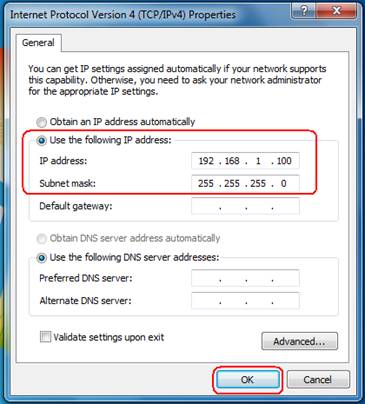
The following TCP/IP Properties window will display and the IP Address tab is open on this window by default. Now you have two ways to configure the TCP/IP protocol below: Setting IP address automatically Select Obtain an IP address automatically, Choose Obtain DNS server automatically, as shown in the Figure below: Figure 0-2… -
Page 100
Note: For Windows 98 OS or before, the PC and router may need to be restarted. Setting IP address manually Select Use the following IP address radio button. And the following items available If the router’s LAN IP address is 192.168.1.1, specify the IP address as 192.168.1.x (x is from 2 to 254), and the Subnet mask as 255.255.255.0. -
Page 101
Figure 0-4 Now: Click OK to keep your settings. -
Page 102: Appendix C: Specifications
Appendix C: Specifications IEEE 802.3, 802.3u, 802.11b and 802.11g, TCP/IP, DHCP Standards and Protocols FCC、CE Safety & Emission One 10/100M Auto-Negotiation LAN RJ45 port, supporting passive Ports 10BASE-T: UTP category 3, 4, 5 cable (maximum 100m) Cabling Type 100BASE-TX: UTP category 5, 5e cable (maximum 100m) Wireless Data Rates 54/48/36/24/18/12/9/6Mbps or 11/5.5/3/2/1Mbps Wireless Encryptions…
-
Page 103: Appendix D: Glossary
Appendix D: Glossary ™ WLAN Transmission Technology — The WLAN device with 2x 2x to 3x eXtended Range to 3x eXtended Range™ WLAN transmission technology make its sensitivity up to 105 dB, which gives users the ability to have robust, longer-range wireless connections. With this range-enhancing technology, a 2x to 3x eXtended Range™…
-
Page 104
2.4GHz, 4.9, 5.2, 5.4, and 5.8GHz bands or licensed frequencies in the UHF or MMDS bands. WLAN (Wireless Local Area Network) — A group of computers and associated devices communicate with each other wirelessly, which network serving users are limited in a local area. http://www.tp-link.com…
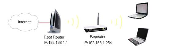
Внимание: TL-WA5110G/TL-WA5210G поддерживает только WEP тип безопасности в режиме Ретранслятор/Универсальный ретранслятор
Информация о корневом маршрутизаторе:
· IP-адрес локальной сети: 1 92.168.1.1
· SSID (имя беспроводной сети): TP — LINK — test
· Тип шифрования: открытый шестнадцатеричный WEP
· Кодовая фраза: 0123456789
Подготовка
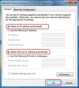
Поскольку функция DHCP на TL-WA5110G/TL-WA5210G отключена по умолчанию, необходимо вручную задать IP-адрес (192.168.1. x ) компьютеру, для совпадения с IP-адресом по умолчанию. Нажмите здесь для подробной инструкции.
К примеру, мы можем настроить IP-адрес локального соединения компьютера: 192.168.1.100/255.255.255.0
Подключите компьютер к точке доступа через кабель Ethernet.
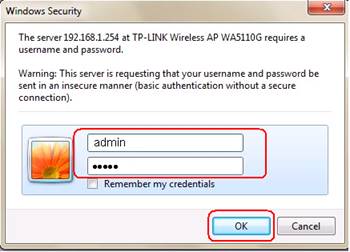
Настройка устройства (TL-WA5110G / TL-WA5210G):
1. Зайдите на веб-страницу управления ретранслятора.
Введите в адресной строке веб-браузера IP-адрес ретранслятора (по умолчанию — 192.168.1.254). Нажмите Enter .

Укажите имя пользователя и пароль (по умолчанию – admin ).
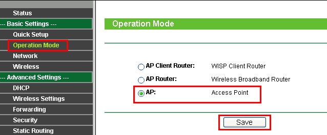
2. Нажмите Operation Mode (Режим работы), выберите режим АР (точки доступа) и нажмите Save (Сохранить).
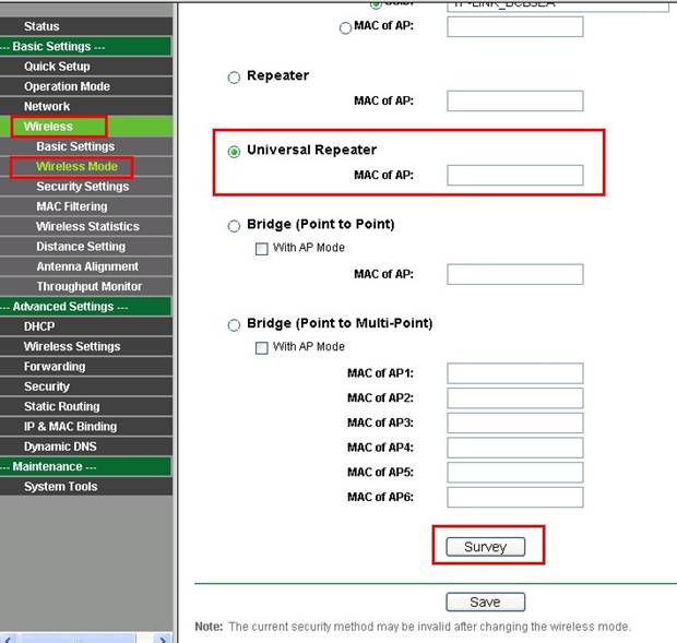
3. Нажмите Нажмите Wireless (Беспроводная связь) -> Wireless Mode (Беспроводной режим), здесь выберите Universal Repeater (Универсальный ретранслятор). Нажмите Survey (Обзор).
(Если корневой маршрутизатор поддерживает функцию WDS, то в качестве Wireless Mode (Беспроводного режима) вы можете выбрать Repeater (Ретранслятор).
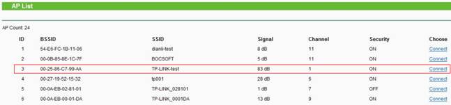
4. Найдите SSID корневого маршрутизатора в списке ТД, нажмите Connect (Соединение).
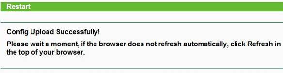
5. Нажмите Save (Сохранить).
Если вы видите проиллюстрированное ниже изображение, подождите, пока оно не обновится до страницы статуса.
6. Укажите те же настройки беспроводной безопасности для коревом маршрутизаторе
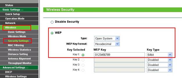
В режиме Ретранслятора/Универсального ретранслятора ТL-WA5110G/TL-WA5210G поддерживает только тип безопасности WEP в режиме Ретранслятор/Универсальный ретранслятор. Если на вашем корневом маршрутизаторе включена безопасность беспроводной сети, убедитесь, чтобы тип безопасности был WEP.
В нашем примере, тип безопасности корневого маршрутизатора — WEP
Нажмите Wireless (Беспроводная связь) -> Security settings (Настройки безопасности).
Выберите WEP , укажите тот же Type (тип), Key Format (Формат ключа) и Key Type (Тип ключа) что и на корневом маршрутизаторе.
Укажите тот же пароль: 0123456789.
Нажмите Save (Сохранить).
7. Нажмите System Tools (Системные инструменты)-> Reboot (Перезагрузка) -> кнопка Reboot ( Перезагрузка) для перезагрузки устройства.
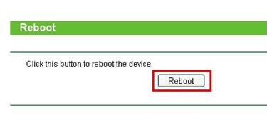
Завершив все указанные выше действия, повторитель будет должным образом работать с корневым маршрутизатором.
ПРИМЕЧАНИЕ:
После завершения настройки смените IP-адрес локального соединения вашего компьютера на IP-адрес, который был указан по умолчанию.
Был ли этот FAQ полезен?
Ваш отзыв поможет нам улучшить работу сайта.
Что вам не понравилось в этой статье?
- Недоволен продуктом
- Слишком сложно
- Неверный заголовок
- Не относится к моей проблеме
- Слишком туманное объяснение
- Другое
Как мы можем это улучшить?
Спасибо
Спасибо за обращение
Нажмите здесь, чтобы связаться с технической поддержкой TP-Link.

1
Для настройки Точки доступа используйте только проводное
соединение.
Адаптер питания можно также подключить напрямую к Точке
доступа. В этом случае вы можете подключить ваш компьютер
напрямую к Точке доступа с помощью кабеля Ethernet.
Отключите все сетевые
устройства, в том числе ваш
компьютер(ы), Адаптер
питания и Точку доступа.
С помощью кабеля Ethernet
подключите Ваш компьютер к
порту LAN, расположенному
на Адаптере питания.
Подсоедините поставляемый
в комплекте Блок питания к
разъему для питания на
Адаптере питания. Вилку
Блока питания подключите к
стандартной электрической
розетке.
С помощью кабеля Ethernet
подсоедините вашу Точку
доступа к порту PoE на
Адаптере питания.
Установка
1
Подключение Устройства
Внимание
Внимание
-
Страница 1
I TL-WA5110G 54M High Power Wireless Access Point Rev: 1.0.0 1910010154[…]
-
Страница 2
COPYRIGHT & TRADEMARKS Specifications are subjec t to change without notice. is a registered trademark of TP-LINK TECHNOLOGIES CO., LTD. Other brands and product names are trade marks or registered trademarks of t heir respective holders. No part of the specificat ions may be reproduced in any form or b y any means or used to make any derivativ[…]
-
Страница 3
FCC STATEMENT This equipment has been tested and found to comply wi th the limits for a Class B digital device, pursuant to part 15 of the FCC Ru les. These limits are designed to pr ovide reasonable protectio n against harmful interference in a residential installation. This equipment ge nerates, uses and can radiate radio frequency energy and, if[…]
-
Страница 4
National Restrictions 2400.0-2483.5 MHz Country Restriction Reason/remark Bulgaria General authorization re quired for outdoor use and public service France Outdoor use limited to 10 mW e.i.r.p. within the band 2454-2483.5 MHz Military Radiolocation use. Refarming of the 2.4 GHz band has been ongoing in recent years to allow current relaxed regulat[…]
-
Страница 5
TP-LINK TECHNOLOGIES CO., LTD TP-LINK TECHNOLOGIES CO., LTD. South Building, No.5 Keyuan Road, Central Zone, Science & Technology Park, Nanshan, Shenzhen, P. R. China DECLARATION OF CONFORMITY For the following equipment: Product Description: 54 M High Power Wireless Access Point Model No.: TL-W A51 10G T rademark: TP-LINK We declare under our […]
-
Страница 6
CONTENTS Package Co nten ts ………………………………………………………………………………………………… …….. 1 Chapter 1. Product O vervie w …………………………………………………………………………………….. 2 1.1 Overview of the Pr oduct …………………………………[…]
-
Страница 7
II 4.7.3 Address Reserv ation ……………………………………………………………………………………. 34 4.8 Wireless sett i ngs ……………………………………………………………………………………………. . 35 4.9 Forw arding ………………………………………………………….[…]
-
Страница 8
III 5.6.1 Basic Setting s…………………………………………………………………………………………….. . 63 5.6.2 Wire less Mode …………………………………………………………………………………………….. 64 5.6.3 Security Sett ings ……………………………………………….[…]
-
Страница 9
1 Package Contents The following items should be found in your package: ¾ One TL-WA5110G 54M High Power Wireless Access Point ¾ One AC power Adapter for TL-WA5110G 54M High Power Wireless Access Point ¾ One Power Injector ¾ Quick Installation Guide ¾ One Resource CD for TL-WA5110G 54M High Power Wireless Access Point, including: z This User Gu[…]
-
Страница 10
2 Chapter 1. Product Overview Thank you for choosing TL-WA5110G 54M Hi g h Pow er Wi r el e ss A c c ess Point 1.1 Overview of the Product The TL-WA5110G 54M High Power Wireless Access Point is dedicated to Small Office/Home Office (SOHO) wireless network solutions. T he TL-WA5110G 54M High Power Wireless Access Point will allow you to connect your[…]
-
Страница 11
3 ¾ Supports PPPoE, Dynamic IP, Static IP Internet Access. ¾ Built-in NAT and DHCP server supporti ng static IP addre ss distributing. ¾ Supports UPnP, Dynamic DNS, Stat ic Routing, VPN Pass-through. ¾ Supports Virtual Server, S pecial Application and DMZ host. ¾ Built-in firewall supporting IP address filteri ng, Domain Name filtering, and MA[…]
-
Страница 12
4 Chapter 2. Hardware Installation 2.1. The Front Panel The front panel of the TL-WA511 0G consists of several LED i ndicators, which is designed to indicate connections. View from left to right. T able 2-1 describes the LE Ds on the front panel of the router. Figure 2-1 Front Panel sketch LED Explanation : Name Status Indication Off No Power Pow[…]
-
Страница 13
5 • Use the Factory Defaults function o n System Tools -> Factory Defaults page in the AP’s Web-based Utility. • Use the Factory Default Reset button: Press and hold the default Reset button for 5 seconds, and then the AP reboot after the System led flash 5 times. • Use the Factory Default Reset button: First, turn off the AP’s p[…]
-
Страница 14
6 4. Adjust the direction of the antenna. Normally, upright is a good direction. 5. Connect the Ethernet Broadband Router to the TL-WA5110G AP. Power on the AP. 6. If you are connecting a desktop PC or laptop to your network, install the TP-LINK Wireless Adapter on the PC. Figure 2-3 To establish an infrastructure netwo rk in AP Client Router mode […]
-
Страница 15
7 Chapter 3. Quick Installation Guide This Chapter will guide you to c onfigure the AP to function in y our network and gain access to the internet through your ISP immediately after success ful configuration. More detailed des cription of the AP’s web-based utility and func tions can be found in “Chapt er 4 Configuring the AP” 3.1. Configure[…]
-
Страница 16
8 Figure 3-1 Success result of Ping command If the result displayed is similar to that shown in Figure 3-2, it means that your PC has not connected to the AP. Figure 3-2 Failure result of Ping command Please check the connection following these steps: 1. Is the connection between your PC and the AP correct? ) Note: The LED of LAN port you link to o[…]
-
Страница 17
9 Figure 3-4 Login Windows ) Note: If the above screen does not pop-up, it means that your Web-browse r has been set to a proxy. Go to Tools menu>Internet Options>Connections>LAN Settings, in the screen that appea rs, cancel the Using Proxy checkbox, and click OK to finish it. If the User Name and Password are correct, you can configure th[…]
-
Страница 18
10 ) Note: The AP supports three mode operatio n modes for multi-user to acce ss the In ternet: AP client router, AP router and AP. In AP client router mode, it can acce ss the Internet wirelessly by you r WISP’s support. In AP router mode, it can access the Inte rnet via ADSL/Cable Modem. In AP mode, it can access a wireless network by using WIF[…]
-
Страница 19
11 Figure 3-9 Quick Setup — Static IP ) Note: The IP parameters should have been provided by your ISP. ¾ IP Address — This is the WAN IP address as seen by external users on the Internet (including your ISP). Enter t he IP address into the field. ¾ Subnet Mask — The Subnet Mask is used for the WA N IP address, it is usually 255.255.255.0 ¾ Defau[…]
-
Страница 20
12 Figure 3-11 Quick Setup — Wireless settings ¾ SSID — Enter a value of up to 32 characters. The same SSID must be assigned to all wireless devices on your network. The defaul t SSID is TP-LINK. This value is case-sensitive. For example, TP-LINK is NOT the same as tp-link . ¾ Region — Select your region from the pull-down lis t. This field speci[…]
-
Страница 21
13 Chapter 4. Configuring the Device in AP Client Router & AP Router Operation Mode This Chapter describes how to configure some advanced settings for your Access Point through the web-based management page. In the following explanations, we will take the device in AP Client Router operati on mode for example. 4.1 Login After your successful lo[…]
-
Страница 22
14 Figure 4-1 Status 1. LAN This field displays the current settings or information for the LAN, including the MAC address, IP address and Subnet Mask. 2. Wireless This field displays basic information or status for wireless function, including Wireless Radio, SSID, Channel, Mode, Wireless MAC address, and IP address. 3. WAN These parameters apply […]
-
Страница 23
15 This field displays the router’s traffic statistics . 5. System Up Time The total up time of the router since it was powered on or reset. 4.3 Quick Setup Please refer to Section 3.2: «Quick Setup.» 4.4 Operation Mode The AP supports three operation mode types, AP Client Router , AP Router and AP . Please select one your want. Clic[…]
-
Страница 24
16 Figure 4-4 LAN ¾ MAC Address — The physical address of the router, as seen from the LAN. The value can’t be changed. ¾ IP Address — Enter the IP address of your router in dotted- decimal notati on (factory default: 192.168.1.1). ¾ Subnet Mask — An address code that determines the size of the network. Normally use 255.255.255.0 as the sub[…]
-
Страница 25
17 Figure 4-5 WAN – Dynamic IP This page displays the WAN IP parameters assi gned dynamically by your ISP, including IP address, Subnet Mask, Defaul t Gateway, etc. Click Renew to renew the IP parameters from your ISP. Click Release to release the IP parameters. MTU Size — The normal MTU (Maximum Transmission Un it) value for most Ethernet networ[…]
-
Страница 26
18 Figure 4-6 WAN — Static IP You should type the following paramet ers into the spaces provided: ¾ IP Address — Enter the IP address in dotted-decim al notation provided by your ISP. ¾ Subnet Mask — Enter the subnet Mask in dotted-decim al notation provided by your ISP, usually is 255.255.255.0. ¾ Default Gateway — (Optional) Enter the gatewa y[…]
-
Страница 27
19 Figure 4-7 WAN — PPPoE ¾ User Name/Password — Enter the User Name and Password provided by your ISP. These fields are case-sensitive. ¾ Connect on Demand — You can configure the router to disconnect your Internet conn ection after a specified period of inactivity ( Max Idle Time ). If your Internet connection has been terminated due to inactiv[…]
-
Страница 28
20 Caution : Sometimes the connection cannot be disc onnected although you s pecify a time to Max Idle Time, since some applications are visiti ng the Internet continually in the background. Click the Connect button to connect imm ediately, Click the Disconnect button to disconnect immediately. Click the Advanced Settings button to set up the advan[…]
-
Страница 29
21 Figure 4-9 MAC Address Clone Some ISPs require that you register the MAC Addr ess of your a dapter, whic h is connected to your cable/DSL Modem or Ethernet during installa tion. Changes are rarely needed here. ¾ WAN MAC Address — This field displays the current MAC address of the WAN port, which is used for the WAN port. If your ISP requires th[…]
-
Страница 30
22 Figure 4-11 Wireless Settings in AP Client Router mode ¾ SSID — Enter a value of up to 32 characters. The same name (SSID) must be assigned to all wireless devices in your network. The default SSID is TP-LINK_xxxxxx (x xxxxx indicates the last six unique characters of each device’s MAC address). This value is case -sensitive. For example, TP-[…]
-
Страница 31
23 Figure 4-12 Wireless Mode ) Note: In AP Client Router, there is only Client mode available shown as Figure 4-12 while in A P Router there is only Access Point mode available shown as Figure 4-14 . ¾ Access Point — Access Point mode allows wireless st ations including AP clients to access the router. • Enable SSID Broadcast — If you select the[…]
-
Страница 32
24 • SSID — Enter the SSID of AP that you want to access. If you select the radio before SSID , the AP client will connect to AP according SSID. • MAC of AP — Enter the MAC address of AP that you w ant to access. If you select the radio before MAC of AP , the AP client will connect to AP according MAC address. ) Note: To apply any settings you […]
-
Страница 33
25 Figure 4-14 Wireless Mode settings in AP Router mode 4.6.3 Securit y Settings You can select one of the following security options:[…]
-
Страница 34
26 Figure 4-15 Wireless Security ¾ Disable Security — The wireless security function ca n be enabled or disabled. If disabled, the wireless stations will be able to connect the device without encryption. It is recommended strongly that you choose one of follo wing options to enable security. ¾ WEP — Select 802.11 WEP security. • Typ e — You can[…]
-
Страница 35
27 1). For 64-bit encryption — You can enter 10 hexadecimal digits (any combination of 0-9, a-f, A-F, zero key is not permitt ed) or 5 ASCII characters. 2). For 128-bit e ncryption — You can enter 26 hexad ecimal digits (any combination of 0-9, a-f, A-F, zero key is not permitted) or 13 ASCII characters. 3). For 152-bit e ncryption — You can enter […]
-
Страница 36
28 Figure 4-16 Wireless MAC address Filtering The Wireless MAC Address Filtering feature allows you to control wireless stations accessing the router, which depend on the station’s MAC addresses. ¾ MAC Address — The wireless station’s MAC address that you want to access. ¾ Status — The status of this entry either Enabled or Disabled . ?[…]
-
Страница 37
29 2. Enter a simple description of the wireless station in the Description field. For example: Wireless station A. 3. Privilege — Select the privileges for this entry, one of Allow / Deny / 64-bit / 128-bit / 152-bit . 4. WEP Key — If you select 64-bit , 128-bit or 152-bit in the Privilege field, enter any combination of hexadecimal digits (0-9, a[…]
-
Страница 38
30 Enabled in the Status pull-down list. Click the Save and the Return button. The filtering rules that configured s hould be similar to the following list: ) Note: 1) If you select the radio button Allow the stations not specified by any enabled entries in the list to access for Filtering Rules, the wireless station B will still not be able to acc[…]
-
Страница 39
31 Figure 4-19 Distance Setting ¾ Use Default Setting: Keep the default setting if the AP is used for indoor environment. If you want to change the di stance, please uncheck the Use Default Setting box . ¾ Distance: Specify the distance value in kilometers, accurate to t he first decimal place. If the distance is set too short or too long, it wil[…]
-
Страница 40
32 Figure 4-21 Wireless Throughput Rate — The Throughput unit. Run Time — How long this function is running. Transmit — Wireless transmit rate information. Receive — Wireless receive rate information. Click the Start button to start wireless throughput monitor. Click the Stop button to stop wireless throughput monitor. 4.7 DHCP Figure 4-22 The DHCP[…]
-
Страница 41
33 provides the TCP/IP configurati on for all the PC(s) that are connec ted to the router o n the LAN. The DHCP Server can be conf igured on the page (shown in Figu re 4-23): Figure 4-23 DHCP Settings ¾ DHCP Server — Enable or Disable the DHCP server. If you disable the Server, you must have another DHCP server within your network , or else you […]
-
Страница 42
34 Figure 4-24 DHCP Clients List ¾ Index(ID)- The index of the DHCP Client ¾ Client Name — The name of the DHCP client ¾ MAC Address — The MAC address of the DHCP client ¾ Assigned IP — The IP address that the router has allocated to the DHCP client. ¾ Lease Time — The time of the DHCP cli ent leased. Before the time is up, DHCP client will re[…]
-
Страница 43
35 Figure 4-26 Add or Modify an Address Reservation Entry T o modify or delete an existing entry: 1. Select a reserved address entry, Click the Modify in the entry if you want to modify it. If you want to delete the entry, click the Delete . 2. Click the Save button. Click the Enable All button to make all entries enabled Click the Disabled All but[…]
-
Страница 44
36 ¾ Disable short preamble — Disable short preamble and us e long pream ble only. 802.11b mode supports only long preamble and this parameter w ill be ignored. It is recommended that you do not change these settings. ¾ RTS threshold — RTS/CTS Threshold, the packet size t hat is used to determine if RTS/CTS should be sent. ¾ Fragmentation thresh[…]
-
Страница 45
37 To setup a virtual server entry, please take the following steps: 1. Click the Add Ne w… in virtual servers page. (pop-up Figure 4-30) 2. Select the service you want to use fr om the Common Service Port list. If the Common Service Port list does not have the serv ice that you want to us e, type the number of the service port or service port ra[…]
-
Страница 46
38 4.9.2 Port Triggering Some applications require multiple connections, li ke Internet games, video conferencing, Internet calling and so on. These applicati ons cannot work with a pure NA T router. Port Triggering is used for some of these applicati ons that can work with a N A T router. You can set up Port Triggering on this page shown in Figure[…]
-
Страница 47
39 7. Click the Save button to save the new rule. Figure 4-32 Add or Modify a Triggering Entry There are many popular applications in the Popular Application list. You can select one, and the application will fill in the Trigger Port , incoming Ports Range boxes automatically. And then, select the Enable option. It has the same effect as adding a n[…]
-
Страница 48
40 Figure 4-33 DMZ To assign a computer or server to be a DMZ server: 1. Click the Enable radio button 2. Enter the IP address of a local PC that is set to be DMZ host in the DMZ Host IP Address field 3. Click the Save button. ) Note: After you set the DMZ host, the firewa ll related to the host will not work. 4.9.4 UPnP The Universal Plug and Play[…]
-
Страница 49
41 Click Disable to disable UPnP Click Refresh to update the Current UPnP Settings List. 4.10 Security Figure 4-35 The Security menu There are five submenus under the Security menu (shown in Figure 4- 35): Fire wall , IP Address Filtering, Domain Filtering, MAC Address Filtering and Advanced Security. Click any of them, and you will be able to conf[…]
-
Страница 50
42 filtering rules for MAC Address Filtering: Allow or Deny the packets specified to pass through the router.. 4.10.2 IP Address Filtering The IP address Filtering feature allows you to cont rol the Internet Access by specific users on your LAN based on their IP addresses. The IP address filtering is set on this page, Figure 4-37: Figure 4-37 IP ad[…]
-
Страница 51
43 4. WAN IP Address — Enter a WAN IP Address or a range of WAN IP Addresses in the field, in dotted-decimal notation format. For example, 61.145.238.6 — 61.145.23 8.47. Keep the field blank, which means all WAN IP Addre sses have been put into the field. 5. WAN Port — Enter a WAN Port or a range of WAN Port s in the field. For example, 25 — 110. K[…]
-
Страница 52
44 Figure 4-39 Domain Filtering Before adding a Domain Filteri ng entry, you m ust ensure that Enable Firewall and Enable Domain Filtering have been selected on the Firewal l page. To Add a Domain filtering en try, click the Add New … button. The page » Add or Modify a Domain Filtering entry » will appear, shown in Figure 4-40: Figure 4[…]
-
Страница 53
45 page. For example, if you want to block the PC(s) on your LAN to access websites www.xxyy.com.cn , www.aabbcc.com and websites with .net in the end on the Internet while no limit for other websites, you should s pecify the following Domain filtering list: 4.10.4 MAC Address Filtering Like the IP Address Filtering page, t he MAC Address Filtering[…]
-
Страница 54
46 4. Click the Save button to save this entry. To add additional entries, repeat steps 1-4. When finished, click the Return button to return to the MAC Address Filtering page. To modify or delete an existing entry: 1. Click the Modify in the entry you want to modify. If y ou want to delete the entry, click the Delete . 2. Modify the information. 3[…]
-
Страница 55
47 Figure 4-43 Advanced Security settings ¾ Packets Statistic interval (5 ~ 60) — The default value is 10. Se lect a value between 5 and 60 seconds from the pull-down list. The Packets Statistic interval value indicates the time section of the packets statistic. The resu lt of the statistic used for analysis by SYN Flood , UDP Flood and ICMP-Flood[…]
-
Страница 56
48 the router from the LAN port. The default va lue is disabled. If enabled, the pi ng packet from the LAN port cannot access the router . (Defends against some viruses) Click the Save button to save the settings. Click the Blocked DoS Host Table button to disp lay the DoS h ost table by blockin g. The p age will appear that shown in Figure 4-44: F[…]
-
Страница 57
49 3. Select Enabled or Disabled for this entry from the Status pull-down list. 4. Click the Save button to save the changes. Figure 4-46 Add or Modify a Static Route Entry T o modify or delete an existing entry: 1. Click the Modify in the entry you want to modify. If y ou want to delete the entry, click the Delete . 2. Modify the information. 3. C[…]
-
Страница 58
50 Figure 4-47 Dyndns.org DDNS Settings To set up for DDNS, follow these instructions: 1. Enter the User Name for your DDNS account. 2. Enter the Password for your DDNS account. 3. Enter the Domain Name you received from dynamic DNS service provider 4. Click the Login button to log in to the DDNS service. ¾ Connection Status — The status of the DD[…]
-
Страница 59
51 To set up for DDNS, follow these instructions: 1. Enter the User Name for your DDNS account. 2. Enter the Password for your DDNS account. 3. Click the Login button to log in to the DDNS service. ¾ Connection Status — The status of the DDNS servic e connection is displayed here. ¾ Domain Name — The domain names are displayed here. Click Logout […]
-
Страница 60
52 4.13 System Tools Figure 4-50 The System Tools menu There are eleven submenus under t he System Tools menu (shown in Figure 4-50): Ti m e , Firmware , Factory Defaults , Backup & Restore , Ping Watch Dog , Speed Test , Reboot , Password , Sysl og , Remote Management and Statistics. Click any of them, and you will be able to configure the cor[…]
-
Страница 61
53 3. Click Save . Click the Get GMT button to get GMT time from the Internet if you have connected to the Internet. If you’re using Daylight saving ti me, please follow the steps below. 1. Select Using Daylight Saving Time . 2. Enter daylight saving begin time and end time in the right blanks. ) Note: 1 This setting will be used for some time-ba[…]
-
Страница 62
54 4.13.3 Factory Defaults This page (shown in Figure 4-53) allows you to restore the factory default settings for the router. Figure 4-53 Restore Factory Default Click the Restore button to reset all configuration settings to their default values. • The default User Name : admin • The default Password : admin • The default IP Address : 192.1[…]
-
Страница 63
55 Figure 4-55 Ping Watch Dog Utility ¾ Enable : Turn on/off Ping Watch Dog. ¾ IP Address : The IP address of the target host wher e the Ping Watch Dog Utility is sending ping packets. ¾ Interval : Time internal between two ping packets which are sent out continuously. ¾ Delay : Time delay before first ping packet is sent out when the dev ice i[…]
-
Страница 64
56 Figure 4-56 Speed Test ¾ Destination IP : The Remote device’s IP address. ¾ Advanced options : This is switch to show advanced test options which are used only for precise estimation. ¾ User : Administrator password of the remote device. It should be filled correctly if you want to get a precise estimation. Otherwise, keep it blank. ) Note:[…]
-
Страница 65
57 Figure 4-57 Reboot the router Click the Reboot button to reboot the router. Some settings of the router will take effect only after rebooting, which include: • Change LAN IP Address. (Sys tem will reboot automatically) • MAC Clone (system will reboot automatically) • DHCP service function. • Static address assignment of DHCP server. • […]
-
Страница 66
58 Figure 4-59 System Log The router can keep logs of all traffic. You c an query the logs to find what happened to the router. Click the Refresh button to refresh the logs. Click the Clear Log button to clear all the logs. 4.13.10 Remote Management You can configure the Remote Mana gement function on this page sho wn in Figure 4-60. This feature a[…]
-
Страница 67
59 ) Note: Be sure to change the router’s defaul t password to a very secure password . In AP mode, port 80 is only supported. The web m anagement port number will be set to 80 when the operation mode changes to AP mode. 4.13.11 Statistics The Statistics page (shown in Figure 4-61) displays the network traffic of each PC on the LAN, including […]
-
Страница 68
60 TCP SYN Tx The total amount of the TCP SYN pack e ts transmitted to WAN in the last Packets Statistic interval seconds. Click the Save button to save the Packets Statistic interval value. Click the Auto-refresh checkbox to refresh automatically. Click the Refresh button to refresh immediately.[…]
-
Страница 69
61 Chapter 5. Configuring the Device in AP Operation Mode This Chapter describes how to configure some advanced settings for your Access Point through the web-based management page in AP operation mode. 5.1 Login After your successful login, you can configur e a nd manage the Access Point. There are ei ght main menus on the left of the Web-based m […]
-
Страница 70
62 Operating Mode, Signal, SSID, Channel, Mode, MAC Address and IP Address . ¾ Traffic Statistics — This field displays the AP’s traffic statistics. ¾ System Up Time — The time of the AP running from it’s powered on or reset . 5.3 Quick Setup Please refer to Section 3.2: «Quick Setup.» 5.4 Operation Mode The AP supports three […]
-
Страница 71
63 255.255.255.0 as the subnet mask. ¾ Gateway — The gateway should be in the same subnet as your IP address. ¾ MAC Address — the physical address of the AP, as seen from the LAN. This value can’t be changed. ) Note: 1 ) If you change the IP Address, you must use the new IP Address to log in the AP. 2 ) If the new LAN IP Address you set […]
-
Страница 72
64 last six unique characters of each device’s MAC address). This value is case -sensitive. For example, TP-LINK is NOT the same as tp-link . ¾ Region -Select your region from the drop-down list. This filed specifies the region where the wireless function of the device can be used. It may be illegal to use the wireless function of the device in […]
-
Страница 73
65 Figure 5-6 Wireless Mode ) Note: AP provides five operational modes: Access Poin t, Client, Repeater, Bridge (point to point), Bridge (point to Multi-point). ¾ Access Point — Access Point mode allows wireless st ations including AP clients to access the router.. • Enable SSID Broadcast — If you select the Enable SSID Broadcast checkbox, the W[…]
-
Страница 74
66 • Enable WDS — The AP client can connect to AP with WDS enabled or disabled. If WDS is enabled, all traffic from wired networks will be forwarded in the format of WDS frames consist of four address fields. If WDS is disabled, three addre ss frames are used. If your AP supports WDS well, pleas e select the option. • SSID — Enter the SSID of A[…]
-
Страница 75
67 network. Also, you can extend the range of the wir eless network with wireless antenna accessories. ¾ Bridge (Point to Point) — This mode bridges the AP and another AP also in bridge mode to connect two wired LANs. Please input the MAC address of the other AP in the field of MAC of AP . AP function can startup also. • With AP mode: If you sel[…]
-
Страница 76
68 Figure 5-9 Point to Multi-point Bridge 1. Configure the Operating M ode of the TL-WA5110G High Power wireless Access Points. • Because it is in the central location, co nfigure TL-WA5110G (AP1) on LAN Segment 1 in Point-to-Multi-Point Bridge mode. The MA C addresses of AP2 and AP3 are required in AP1. • Configure TL-WA5110G (AP2) on LAN Segm[…]
-
Страница 77
69 the wireless network with wireless antenna accessories. ) Note: To apply any settings you have al tered on the page, please click the Save button, and wait the AP reboot automatically. Click Survey will show th e site list of scanning result shown as Figure 5-10. Figure 5-10 AP List ¾ BSSID — The BSSID of the AP, usually al so the MAC address o[…]
-
Страница 78
70 Figure 5-11 Wireless Security ¾ Disable Security — The wireless security function ca n be enabled or disabled. If disabled, the wireless stations will be able to connect the device without encryption. It is recommended strongly that you choose one of follo wing options to enable security. ¾ WEP — Select 802.11 WEP security. • Typ e — You can[…]
-
Страница 79
71 1). For 64-bit encryption — You can enter 10 hexadecimal digits (any combination of 0-9, a-f, A-F, zero key is not permitt ed) or 5 ASCII characters. 2). For 128-bit e ncryption — You can enter 26 hexad ecimal digits (any combination of 0-9, a-f, A-F, zero key is not permitted) or 13 ASCII characters. 3). For 152-bit e ncryption — You can enter […]
-
Страница 80
72 Figure 5-12 Wireless MAC address Filtering The Wireless MAC Address Filtering feature allows you to control wireless stations accessing the router, which depend on the station’s MAC addresses. ¾ MAC Address — The wireless station’s MAC address that you want to access. ¾ Status — The status of this entry either Enabled or Disabled . ?[…]
-
Страница 81
73 2. Enter a simple description of the wireless station in the Description field. For example: Wireless station A. 3. Privilege — Select the privileges for this entry, one of Allow / Deny / 64-bit / 128-bit / 152-bit . 4. WEP Key — If you select 64-bit , 128-bit or 152-bit in the Privilege field, enter any combination of hexadecimal digits (0-9, a[…]
-
Страница 82
74 Enabled in the Status pull-down list. Click the Save and the Return button. The filtering rules that configured s hould be similar to the following list: ) Note: 1) If you select the radio button Allow the stations not specified by any enabled entries in the list to access for Filtering Rules, the wireless station B will still not be able to acc[…]
-
Страница 83
75 Figure 5-15 Distance Setting ¾ Use Default Setting: Keep the default setting if the AP is used for indoor environment. If you want to change the di stance, please uncheck the Use Default Setting box. ¾ Distance: Specify the distance value in kilometers, accurate to t he first decimal place. If the distance is set too short or too long, it will[…]
-
Страница 84
76 5.6.8 Throughput Moni tor This page allows you to view the wireless throughput information Figure 5-17 Wireless Throughput Rate — The Throughput unit. Run Time — How long this function is running. Transmit — Wireless transmit rate information. Receive — Wireless receive rate information. Click the Start button to start wireless throughput monito[…]
-
Страница 85
77 5.7.1 DHCP Settings The router is set up by default as a DHCP (Dyna mic Host Configuration Protocol) server, whic h provides the TCP/IP configurati on for all the PC(s) that are connec ted to the router o n the LAN. The DHCP Server can be conf igured on the page (shown in Figu re 5-19): Figure 5-19 DHCP Settings ¾ DHCP Server — Enable or Disabl[…]
-
Страница 86
78 Figure 5-20 DHCP Clients List ¾ Index(ID)- The index of the DHCP Client ¾ Client Name — The name of the DHCP client ¾ MAC Address — The MAC address of the DHCP client ¾ Assigned IP — The IP address that the router has allocated to the DHCP client. ¾ Lease Time — The time of the DHCP cli ent leased. Before the time is up, DHCP client will re[…]
-
Страница 87
79 Figure 5-22 Add or Modify an Address Reservation Entry T o modify or delete an existing entry: 1. Select a reserved address entry, Click the Modify in the entry if you want to modify it. If you want to delete the entry, click the Delete . 2. Click the Save button. Click the Enable All button to make all entries enabled Click the Disabled All but[…]
-
Страница 88
80 ¾ RTS threshold — RTS/CTS Threshold, the packet size t hat is used to determine if RTS/CTS should be sent. ¾ Fragmentation threshold — The maximum packet size used for fragmentation. ¾ Beacon Interval — The interval time between two successive beacons. ¾ Power — The transmit power of the access point . . 5.9 Sy stem Tools Figure 5-24 The Sys[…]
-
Страница 89
81 1. Download a more recent firmware upg rade file from the TP-LINK website ( www.tp-link.com ). 2. Click Browse to view the folders and select the downloaded file. 3. Click Upgrade . ¾ Firmware Version — Displays the current firmware version. ¾ Hardware Version — Displays the current hardware vers ion. The upgrade file must accord with the curr[…]
-
Страница 90
82 To restore the AP’s configuration, please take the following steps: • Click Browse to find the location of configuration file which you want to restore. • Click Restore to update the configura tion with the file whose path is the one you have input or selected in the blank. ) Note: 1. The current configuration will be cover ed by the up[…]
-
Страница 91
83 administrator Username and Password under Advance options to get a precise estimation if the remote device is TL-WA5110G too. Figure 5-29 Speed Test ¾ Destination IP : The Remote device’s IP address. ¾ Advanced options : This is switch to show advanced test options which are used only for precise estimation. ¾ User : Administrator password […]
-
Страница 92
84 5.9.6 Reboot This page allows you to reboot the AP on the screen below ( Figure 5 -30). Figure 5-30 Reboot the AP Click Reboot to reboot the AP. Some settings of the AP will take effe ct only after rebooting, which include: • Change LAN IP Address. (Syste m will reboot automatically) • Upgrade the firmware of the AP (s ystem will reboot auto[…]
-
Страница 93
85 Click Save when finished. Click Clear All to clear all. 5.9.8 Syslog This page allows you to query the Logs of the AP on the screen below Figure 5-32). Figure 5-32 System Log The AP can keep logs of all tra ffic. You can query the logs to find out what happened to the AP. Click Refresh to refresh the logs. Click Clear ALL to clear all the logs.[…]
-
Страница 94
86 Appendix A: FAQ 1. How do I configure the router to access the Internet by ADSL users? 1) First, configure the ADSL Modem configured in RFC1483 bridge model. 2) Connect the Ethernet cable from your ADSL Modem to the WAN port on the router. The telephone cord plugs into the Line port of the ADSL Modem. 3) Login to the router, click t he “Networ[…]
-
Страница 95
87 register, login to the router and click the «Net work» menu link on the left of your browser, and then click «MAC Clone» submenu link. On the «MAC Clone» page, if your PC’s MAC address is proper MAC address, click the «C lone MAC Address» button and your PC’s MAC address will fill in the «WAN MAC […]
-
Страница 96
88 ) Note: Your opposite side should call your WAN IP, which is displayed on the “Status” page. 4) How to enab le DMZ Host: Login to the router , click the “Forwarding” menu on the left of your browser, and click «DMZ» submenu. On the «DMZ» page, click “Enable” radio an d type your IP address into the “DMZ Host IP […]
-
Страница 97
89 Figure A-8 Virtual Servers A-9 Add or Modify a Virtual server Entry 5. The wireless stations cannot connect to the router. 1) Make sure the «Wireless Router Radio» is enabled. 2) Make sure that the wireless stations ‘ SSID accord with the router’s SSID. 3) Make sure the wireless stations have the right KEY for encryption when[…]
-
Страница 98
90 Appendix B: Configuring the PCs In this section, we’ll introduce how to install and configure the TCP/IP corr ectly in Windows XP. First make sure your Ethernet Adapter is wo rking, refer to the adapter’s manual if needed. 1. Configure TCP/IP component 1) On the Windows taskbar, click the Start button, and then click Control Panel . 2) Click[…]
-
Страница 99
91 Figure 0-2 5) The following TCP/IP Properties window will display and the IP Address tab is open on this window by default. Now you have two ways to configure the TCP/IP protocol below: ¾ Setting IP address automatically Select Obtain an IP address automatically , Choose Obtain DNS server automatically , as shown in the Figure below:[…]
-
Страница 100
92 Figure 0-3 ) Note: For Windows 98 OS or before, the PC and router may need to be restarted. ¾ Setting IP address manually 1 Select Use the follow ing IP address radio button. And the fo llowing items available 2 If the router’s LAN IP addre ss is 192.168.1.1, specify the IP address as 192.168.1.x (x is from 2 to 254), and the Subnet mask a[…]
-
Страница 101
93 Figure 0-4 Now: Click OK to keep your settings.[…]
-
Страница 102
94 Appendix C: Specifications General Standards and Protocols IEEE 802.3, 802.3u, 802.11b and 802.11g, TCP/IP, DHCP Safety & Emission FCC 、 CE Ports One 10/100M Auto-Negotiation LAN RJ45 port, supporting pa ssive PoE Cabling Type 10BASE-T: UTP category 3, 4, 5 cable (maximum 100m) EIA/TIA-568 100 Ω STP (maximum 100m) 100BASE-TX: UTP categor[…]
-
Страница 103
95 Appendix D: Glossary ¾ 2x to 3x eXtended Range ™ WLAN Transmission Technology — The WLAN device with 2x to 3x eXtended Range™ WLAN transmission tech nology make its sensitivity up to 105 dB, which gives users the ability to have robust, longer-range wireless c onnections. With this range-enhancing technology, a 2x to 3x eXtended Rang e™ b[…]
-
Страница 104
96 152-bit shared key algorithm, as des cribed in the IEEE 802.11 standard. ¾ Wi-Fi — is a trademark of the Wi-Fi Alliance, founded in 1999 as Wi reless Internet Compatibility Alliance (WICA), comprising more than 300 com panies, whose products are certified by the Wi-Fi Alliance, based on the IEEE 802.11 standards (also ca lled Wireless LAN (WLAN[…]