-
Contents
-
Table of Contents
-
Bookmarks
Quick Links
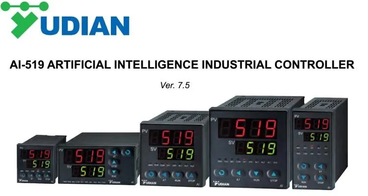
AI SERIES ARTIFICIAL INTELLIGENCE INDUSTRIAL CONTROLLER
AI-518/518P Operation Instruction
Ver. 7.1
Related Manuals for Yudian AI Series
Summary of Contents for Yudian AI Series
-
Page 1
AI SERIES ARTIFICIAL INTELLIGENCE INDUSTRIAL CONTROLLER AI-518/518P Operation Instruction Ver. 7.1… -
Page 2: Table Of Contents
CONTENTS SUMMARY …………………………..1 EATURES RDERING EFINITION MODULES New advanced module technology ENTINANCE TECHNICAL SPECIFICATION ……………………… 4 REAR TERMINAL LAYOUT AND WIRING …………………. 6 DISPLAYS AND OPERATIONS ……………………..8 RONT ANEL ESCRIPTION ISPLAY TATUS PERATION ESCRIPTION 4.2.1 Display status switch 4.2.2 Set Value Setting 4.2.3…
-
Page 3: Summary
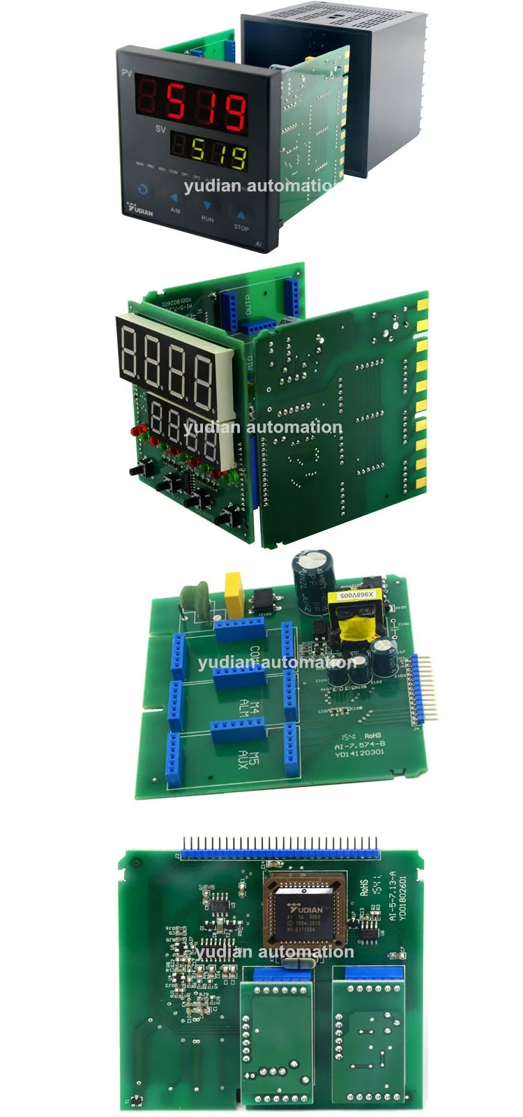
Ordering Code Definition Advanced modularized hardware design is utilized for AI series instruments. There are maximum five module sockets: multi-function input/output (MIO), main output (OUTP), alarm (ALM), auxiliary output (AUX) and communication (COMM). The input specification can be selected as thermocouple, RTD, or linear current/voltage.
-
Page 4
symbols. ① Instrument model AI-518 High accuracy controller with measurement accuracy 0.3%F.S. It adopts artificial intelligent control technology, and has the functions of control, alarm, retransmission and communication. AI-518P Add 30 segment program control to AI-518. ② Front panel dimension Depth Front Panel Cut-out… -
Page 5: Modules
circuit; each channel can trigger TRIAC or a pair of inverse parallel SCR with current of 5-500A) “Burn-proof” single-phase thyristor phase-shift trigger output module (trigger one loop of TRIAC or a pair of inverse parallel SCR with current of 5-500A), suitable for 200~240VAC power supply.
-
Page 6: New Advanced Module Technology
Clean and clearance is needed. Time won’t influence the accuracy of AI intruments,so don’t try to change parameter by changing Sc parameter. If problem happens, please return to YUDIAN factory. AI controllers are default with 60 days warranty after the data of departure factory.During this period, free repair is available.
-
Page 7
Instrument Input range K(-100~1300℃), S(0~1700℃), R(0~1700℃), T(-200~+390℃), E(0~1000℃), J(0~1200℃), B(600~1800℃), N(0~1300℃), WRe3-WRe25(0~2300℃), WRe5-WRe26(0~2300℃) Cu50(-50~+150℃), Pt100(-200~+800℃) Linear Input: -9990~30000 defined by user. Measurement accuracy : 0.3%FS ± 0.1℃ Resolution : 0.1℃ (automatically change to 1℃ when the temperature is high than 999.9℃) or 1℃ selectable … -
Page 8: Rear Terminal Layout And Wiring
3. Rear Terminal Layout and Wiring Wiring graph for instruments except D and D2 dimension. 100-240VAC~ Thyristor trigger output(K1/K3) OUTP Thyristor trigger output(K3) COMM Thyristor trigger output(K3) The graph suits for upright instruments with dimension A, C or E 0-5V 1-5V For instruments with dimension F, just clockwise rotate the graph 90 degree,…
-
Page 9
module is installed in COMM and parameter “bAud” is set to 1, then on-off signal can be inputted, and SV1 and SV2 can be switched by connecting a switch between terminals 3 and 4. Wiring graph of D2 dimension instruments (48*48mm) P.S.:0-5 1-5 is not available ,transfer to 0-500mV or 100-500mV input. -
Page 10: Displays And Operations
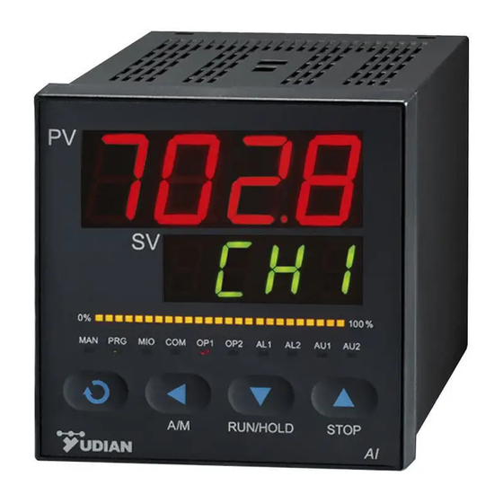
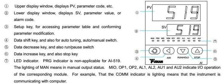
4. DISPLAYS AND OPERATIONS Front Panel Description ① Upper display window, displays parameter code, etc. ② Lower display window, displays SV, parameter value, or alarm ③ Setup key, for accessing parameter table and conforming parameter modification. ④ Data shift key, and auto/manual control switch.
-
Page 11: Operation Description
4.2.2 If the lower display window alternately display “HIAL”, “LoAL”, “HdAL” or “LdAL”, it means high limit alarm, low limit alarm, deviation high alarm, and deviation low alarm occurs. The alarm display can also be turned off by setting parameter “cF”. 4.2.3.
-
Page 12
On the basis of disturbance caused by on-off control, oscillation period, amplitude and waveform are analyzed to calculate optimum control parameters. The auto tuning for AI series instrument will gratify for 90% users. Due to the complexity of the automatic process, parameters calculated by auto tuning are probably not the optimal values on some special occasion (mentioned as follows). -
Page 13: Program Operation (For Ai-518P Only)
Program operation (for AI-518P only) 4.4.1 Setup program once and release in the display status ①, the instrument will be in the setup program Press the key 、 status. The setpoint of the current program StEP will be displayed. Pressing or c can modify the value.
-
Page 14: Parameters And Settings
5. PARAMETERS AND SETTINGS The Full Parameter Table Setting Code Name Description Range Alarm is triggered when PV (Process Value) >HIAL; -1999~ alarm is released when PV<HIAL-dF; HIAL High limit alarm +9999 To disable high limit alarm, set HIAL=9999 units or Every alarm can be defined to control AL1,AL2,AU1,AU2 Alarm triggered when PV<LoAL;…
-
Page 15
Lag time parameter “t” is a new parameter seconds introduced important parameter for AI artificial intelligence algorithm. AI series instrument can use parameter “t” to do fuzzy calculation, and therefore overshoot and hunting do not easily occurs and the control have the best responsibility at the time. -
Page 16
Input spec. Input spec. Cu50 Pt100 stock 0~75mV 0~80ohm resistor input 0~400ohm resistor input 0~20mV voltage input 0~100mV voltage input 0~60mV voltage input WRe3-WRe25 0~1V voltage input WRe5-WRe26 0.2~1V voltage input Input specification extended input 0~37 1~5V voltage input Code specification radiation type… -
Page 17
OP1 select the control output type: OP1=OP1.A x 1 + OP1.B x 10 OP1.A shows the output type of OUTP. It should be compatible with the module installed in OUTP sockets. OP1.A=0, if output modules such as SSR voltage output, relay contact discrete output, thyristor cross zero trigger output, and TRIAC no-contact discrete output are installed in OUTP. -
Page 18
From right side to left side, the first, second, third and fourth digit of ALP individually indicate the alarm output terminal of HIAL, LoAL, HdAL, and LdAL. 0 shows no output. 1 and 2 are spare for future use. 3,4,5 and 6 respectively indicate alarms outputted to AL1, AL2, AU1 or AU2. -
Page 19
The value of dL will determine the ability of filtering noise. There is one intermediate-value filter system and one second order integral digital filter system in AI series instrument. Intermediate value filter takes intermediate value among three continuous values, while integral filter has the same effect as resistance-capacity integral filter. -
Page 20: Additional Remarks Of Special Functions
StEP value can not be modified. Loc=808, allowed to set all parameters, program and StEP value. Note: that 808 is the password of all AI series instrument. In application the instrument should be set to other values to protect from modifications of parameters.
-
Page 21: Alarm Blocking At The Beginning Of Power On(Cf.b=1)
5.2.2 Single phase contact output (oP1-8) Phase-shifting output is usually realised by TRIAC.but it will has influence on heater, so please make sure of the anti-interference of other equipments when use it. 5.2.3 SV limit setting (only for AI-518,and CF.C=0) SV is usually between HIAL and LoAL.
-
Page 22: Widely Used Control Mode
RS232/RS485 changable. One computer with two communication interfaces are workable with 100 units controllers. Diffferent communication addresses are needed. AI-485 AIBUS is advised to be used with AI series instruments. Computer AI series intruments upto 100units 6.
-
Page 23: Ai Artificial Intelligent Regulator
4~20mA. 6.3 AI artificial intelligent regulator AI series controllers are developed with advanced AI artificial intelligent fuzzy logic control mode, high accuracy. Advanced Auto turning function can help users to set parameters. AI-518P has the programmable control function. When CtrL is 1-4, then the unit is able to regulate other functions.
-
Page 24: Programming And Operation Editting
(cooling-down). This phenomenon is normal. 7.2 Programming and operation editting Programming of AI series instrument has uniform format of temperature-time-temperature, which means that temperature set for current StEP will change to temperature set for next StEP after the time set for the current StEP.
-
Page 25
jump to StEP5. StEP5: C05=160 , t05=0 The program get in Hold state, and run operation executed by operator is needed for the program to continue running to StEP 6. StEP6: C06=100 , t06=-151 Alarm 1 is switch off, and jump to StEP1 to start from beginning. In this example, it is assumed that the positive deviation alarm is set to 5℃. -
Page 26
AI-518P has the advanced function of flexible program arrangement. Normally, when the program stops, the StEP will be automatically set to1. Thus if StEP is not change to other value, a program will start from step1. If multiple curves are defined, the control can jump to different curve by setting step 1 as jump segment.
- Manuals
- Brands
- Yudian Manuals
- Temperature Controller
- AI-208
- Operation manual
-
Bookmarks
Quick Links
Yudian (H.K.) Automation Technology Co. Ltd.
Website:
http://www.yudian.us http://www.yudian.com.hk
Email:
sales@yudian.com.hk
Tel: +852-2770 8785
Fax: +852-2770 8796
ARTIFICIAL INTELLIGENCE
TEMPERATURE CONTROLLER
AI-208 (V7.8)
Operation Manual
Related Manuals for Yudian AI-208
Summary of Contents for Yudian AI-208
-
Page 1
Yudian (H.K.) Automation Technology Co. Ltd. Website: http://www.yudian.us http://www.yudian.com.hk Email: sales@yudian.com.hk Tel: +852-2770 8785 Fax: +852-2770 8796 ARTIFICIAL INTELLIGENCE TEMPERATURE CONTROLLER AI-208 (V7.8) Operation Manual… -
Page 2
Email: sales@yudian.com.hk Tel: +852-2770 8785 Fax: +852-2770 8796 I. Model Order Code The type of AI-208 is made up of 4 parts: AI-208 Part 1 (Series) Part 2 (Size) Part 3 (Oupt) Part 4 (AUX) 1. (Part 1) Model Series AI-208, standard temperature controller , 0.3%FS±1℃… -
Page 3: Technical Specification
Dual relay output module Output module (Capacity: 2A/250VAC, normal open, support AU1 and AU2 alarm output) SSR voltage output module (30mA/5VDC) * D1-sized controller is fixed to SSR output(G) and no module option provided, i.e. AI-208-D1-G, AI-208-D1-G-L0 or AI-208-D1-G-L5 must be specified upon order. II. TECHNICAL SPECIFICATION 1.
-
Page 4: Front Panel And Operation
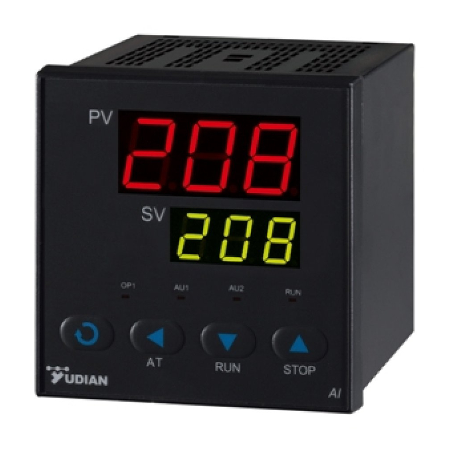
Yudian (H.K.) Automation Technology Co. Ltd. Website: http://www.yudian.us http://www.yudian.com.hk Email: sales@yudian.com.hk Tel: +852-2770 8785 Fax: +852-2770 8796 III. FRONT PANEL AND OPERATION ① Process Value(PV), or parameter code Set Value(SV), alarming code, or value of a parameter ② Setup key, accessing parameter table, and confirming change.
-
Page 5
Yudian (H.K.) Automation Technology Co. Ltd. Website: http://www.yudian.us http://www.yudian.com.hk Email: sales@yudian.com.hk Tel: +852-2770 8785 Fax: +852-2770 8796 V. PARAMETER AND SETTING Title Description Range Parameter Field Parameter Table (Press and hold for 2 seconds to access) Alarm on when PV (Process Value) >HIA;… -
Page 6
Yudian (H.K.) Automation Technology Co. Ltd. Website: http://www.yudian.us http://www.yudian.com.hk Email: sales@yudian.com.hk Tel: +852-2770 8785 Fax: +852-2770 8796 Smaller value will result in higher control accuracy. For SSR output, generally 0.5 to 3 seconds. For Relay output, generally 15 to 40 seconds, because small value will… -
Page 7
Yudian (H.K.) Automation Technology Co. Ltd. Website: http://www.yudian.us http://www.yudian.com.hk Email: sales@yudian.com.hk Tel: +852-2770 8785 Fax: +852-2770 8796 VI. INSTRUMENT INSTALLATION AND WIRING DIAGRAM Panel dimension A1, B1, E1 or F1 Panel dimension A, B, E or F Main Output Alarm Output…
- What is the default setting of temperature controller AI-508 / AI-509?
The default setting can be found of the manual in the download section underneath.
- Is there any driver of National Instrument LabView?
We are working on it. Reference: http://forums.ni.com/t5/Multifunction-DAQ/Automate-temperature-controller/m-p/1618094/highlight/false#M64849
- Does YUDIAN temperature controller / indicator support MODBUS?
Yes. YUDIAN instruments support AIBUS. Starting from version 8.0 or above, YUDIAN instruments support both AIBUS and MODBUS. Setting AF.H=1 (x 128) can activate MODBUS support.
- Which model supports MODBUS?
Temperature Controller: AI-526, AI-526P Temperature Indicator: AI-5201.
- How can I find out the serial number?
Locate the small white label on the side of enclosure or back of the panel (LCD instrument). You may also refer to the details or other methods to find out the model number and firmware version
below.
![]()
![]()
Temperature controller AI-508 / AI-509 Default Setting — Operation Manual
Q: What is the default setting of temperature controller AI-508 / AI-509?
A: The default setting can be found of the manual. Please note the default parameter Act should be «rE».
TemperatureControllerAI508509v75r1.pdf
Adobe Acrobat document [347.9 KB]
![]()
Paperless Recorder AI-3170S: Analysis Software YDR_V1_01_07
Early AI-3170S required users to run this Analysis Software to read the encrypted data in the USB drive. Only on Windows platform.
Yudian_Analysis_Software_YDR_V1_01_07.zi[…]
Compressed archive in ZIP format [26.8 MB]
![]()
Paperless Recorder AI-3170S: YUDIAN.BK
This is a file for recognition. Please unzip and copy this «yudian.bk» into the root directory of the USB drive and do not remove it. Otherwise no data will be exported.
yudian_bk.zip
Compressed archive in ZIP format [116 Bytes]
https://www.fedex.com/fedextrack/?tracknumbers=
us
http://www.ups.com/WebTracking/OnlineTool?trackNums=
en_US
Описание и отзывы
Характеристики
Регулятор температуры PID
Описание продукта:

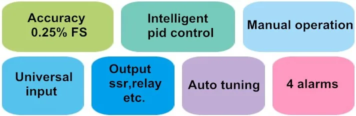
Основные характеристики для регулятора температуры PID Yudian AI-518
- Универсальные термопары, RTDs и линейные сигналы тока/напряженияВыбираемые, интегрированные Нелинейные градационные столы, Цифровая калибровка и автоматическая нулевая технология, и достижение точного и стабильного измерения.
- Применение усовершенствованного алгоритма управления искусственным интеллектом AI с функцией автоматической настройки, без перебоев.
- Поставляется с автоматическим/ручным бескорпусным переключателем и функцией мягкого запуска.
- Применение передовой модульной структуры, удобно обеспечивая множество вариантов выхода, может удовлетворить различные требования приложения и сделать быструю доставку и легкое обслуживание.
- Высокое качество и производительность аппаратного дизайна, используя высокопроизводительный танталовый конденсатор или керамический конденсатор. По сравнению с конкурирующими моделями, он потребляет меньше электроэнергии, переживает меньше перегрева температуры, обеспечивает более высокую стабильность и может работать в более широком диапазоне температур.
- ISO9001 и CE сертифицированы, достигая мирового уровня качества, анти-помехи и безопасности.
Размер для регулятора температуры PID AI-518
| Размер | Передняя панель (Ш * В) | Вырез (Ш * В) | Глубина от монтажной поверхности |
| А | 96*96 мм | 92*92 мм |
100 мм |
| B | 160*80 мм | 152*76 мм | 100 мм |
| C | 80*160 мм | 152*76 мм | 100 мм |
| D | 72*72 мм | 68*68 мм | 95 мм |
| D2 | 48*48 мм | 45*45 мм | 95 мм |
| E | 48*96 мм | 45*92 мм | 100 мм |
| F | 96*48 мм | 92*45 мм | 100 мм |

Передняя панель и управление для PID регулятора температуры
Упаковка & Доставка
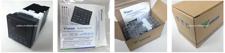
Вы получите:
- Контроллер температуры;
- Бумага руководства пользователя;
- Гарантийный талон на один год/3 года и сертификат качества;
- Этикетка единиц;
- Пара монтажных кронштейнов;
- Хорошая картонная коробка с логотипом Yudian.
Больше продуктов
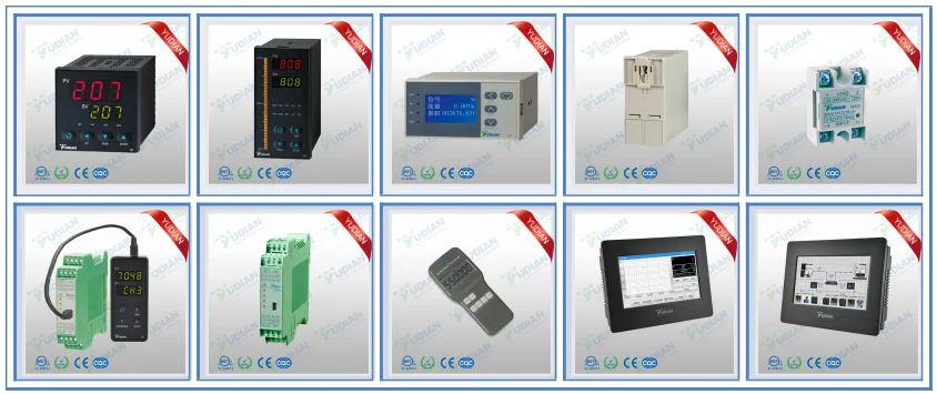
Похожие товары

www.instrumentsolutions.com.au
ARTIFICIAL INTELLIGENCE
TEMPERATURE CONTROLLER
AI-208 (V7.6)
User Manual
www.instrumentsolutions.com.au
I. Model Code Symbol
The type of AI-208 is made up of 4 parts:
AI-208
A
G
L2
Part 1 (Series)
Part 2 (Size)
Part 3 (Oupt)
Part 4 (AUX)
1. (Part 1) Model Series
AI-208, standard temperature controller , 0.3%FS±1℃ accuracy.
Multiple thermocouples and RTDs are selectable
Suitable for 0~999℃ application. Maximum support two alarms contact output
Universal voltage input (100~240VAC)
2. (Part 2) Front panel dimension
Front Panel
Cut Out
width×height
width×height
A
96×96mm
92×92mm
100mm
B
160×80mm
152×76mm
100mm
D
72×72mm
68×68mm
95mm
D2
48×48mm
45×45mm
95mm
E
48×96mm
45×92mm
100mm
F
96×48mm
92×45mm
100mm
Size
Depth Behind Mounting Surface
www.instrumentsolutions.com.au
3. (Part 3 and 4) indicate the module installed in OUTP and AUX sockets.
Allowed modules in each socket are as below:
Allowed Type
N
L
L1
L5
G
Module Socket
√
3. OUTP (main output)
√
4. AUX (Auxiliary output)
√
√
√
N
(or none) no module installed
L
Relay contact output module (Capacity: 5A/250VAC, normal open)
L1
Relay contact output module (Capacity: 2A/250VAC, normal open/ normal close)
L5
Dual relay output module Output module (Capacity: 2A/250VAC, normal open, support AU1 and
AU2 alarm output)
G
SSR voltage output module (30mA/5VDC)
II. TECHNICAL SPECIFICATION
1. Input type :
Thermocouple: K, E, J, N
Resistance temperature detector: Pt100
2. Instrument Input range :
K, E, J, N : (0~+999)℃ ;
Pt100: (0~+800)℃
3. Measurement accuracy : 0.3%FS±1℃
4. Temperature display resolution : 0 or 0.0 (0.0 just for 0~99.9 display)
5. Control mode:
On-off control mode, or
PID control with the function of parameter auto tuning.
6. Alarm function: High limit alarm, Lower limit alarm, Deviation High Alarm; providing the function of
alarm blocking at the beginning of power on.
7. Power supply voltage rating: 100-240VAC, -15%, +10% / 50-60Hz.
8. Power consumption: ≤2W
9. Ambient temperature: -10~+60℃, Humidity: 0~90RH%
www.instrumentsolutions.com.au
III. FRONT PANEL AND OPERATION
①
Process Value(PV), or parameter code
②
Set Value(SV), alarming code, or value of a parameter
③
Setup key, for accessing parameter table, and confirming change.
④
Data shift key, also for activating auto turning
⑤
Data decrease key
⑥
Data increase key
⑦
Status display LED,
OP1, AU1, AU2, and RUN indicate I/O operation of the
corresponding module.
Basal display status:
When power on, will shows the process value (PV) and the set point (SV). lf the input signal is out of the measurable range (for example,
the thermocouple or RTD circuit is break, or input specification sets wrong). Instrument will alternately display “orA”, and limit alarm of PV,
moreover, instrument will automatically stop the output.
IV. OPERATION DESCRIPTION
●
Set Value Setting:
In basal display status, if the parameter lock “Loc” isn't locked,
key to decrease the value,
pressing
SPH.
●
or
we can set setpoint (SV) by pressing
key to increase the value, and
.
Press
key to move to the digit expected to modify.
Keep
, the speed of decreasing or inscreasing value get quick.
、
or
The range of setpoint is between the parameter
The default range is 0 to 400.
Parameter Setting:
In basal display status, press
and hold for about 2 seconds can access Field Parameter Table.
next parameter; if parameter have not locked, pressing
return to the preceding parameter. Press
、
or
Pressing
can modify a parameter.
(don't release) and then press
can go to the
Press and hold
parameter table. The instrument will escape auomatically from the parameter table if no key is pressed within 30 seconds.
Loc=808 and then press
●
can
key simultaneously can escape from the
Setting
can access System Parameter Table.
AI artificial intelligence control and auto tuning
When AI artificial intelligence control method is chosen (CrL=AI), the PID parameters can be obtained by running auto-tuning.
basal display status, press
to “on”, then press
for 2 seconds, the “At” parameter will appear.
to active the auto-tuning process.
Press
During auto tuning, the instrument executes on-off control.
times of on-off action, the instrument will obtain the optimal control parameter value.
press and hold the
In
to change the value of “At” from “oFF”
After 2-3
If you want to escape from auto tuning status,
key for about 2 seconds until the "At" parameter appear again.
Change “At” from “on” to “oFF”, press
to
confirm, then the auto tuning process will be cancelled.
Note 1:
If the setpoint is different, the parameters obtained from auto-tuning are possible different.
often-used value or middle value first, and then start auto-tuning.
be set at the highest applicable temperature.
So you’d better set setpoint to an
For the ovens with good heat preservation, the setpoint can
Depending on the system, the auto-tuning time can be from several seconds to
several hours.
Note 2:
Parameter Ctl (on-off differential, control hysteresis) has influence on the accuracy of auto-tuning.
value of Ctl, the higher the precision of auto tuning.
from error action around setpoint due to the oscillation of input.
Note 3:
Generally, the smaller the
But Ctl parameter value should be large enough to prevent the instrument
AI series instrument has the function of self-learning.
Ctl is recommended to be 2.0.
It is able to learn the process while working.
The control effect at the
first run after auto tuning is probably not perfect, but excellent control result will be obtained after a period of time because of
self-learning.
www.instrumentsolutions.com.au
V. PARAMETER AND SETTING
Field parameter table (Press
Code
Name
HIA
High limit alarm
LoA
Lower limit alarm
HdA
Deviation high
alarm
Loc
Parameter lock
AHY
Hysteresis
and hold for 2 seconds to access)
Description
Alarm on when PV (Process Value) >HIA;
alarm off when PV<HIA-AHY
Alarm on when PV (Process Value) < LoA;
alarm off when PV > LoA+AHY
Alarm on when PV-SV>HdA;
alarm off when PV-SV<HdA-AHY
Loc=0~1: Allowed to modify parameters HIA, LoA, HdA and SV.
Loc=2~3: Allowed to modify parameters HIA, LoA, HdA. But cannot
change SV.
Loc=4~255: NOT allowed to modify any parameters and SV.
Loc=808, Set to 808 and press
, allowed modify all parameters.
Avoid frequent alarm on-off action because of the fluctuation of PV,
usually sets to AHY=2
Alarm
HdA
LoA
HIA
(x100)
(x10)
(x1)
None
0
0
0
AU1
1
1
1
AU2
2
2
2
Output to
AOP
Alarm output
assignment
Setting Range
0~999℃
0~999℃
0~999℃
0~255
0~200
0~444
eg: AOP=201 means HdA have alarm action from AU2, LoA, no alarm
action , HIA alarm action output from AU1.
z
CrL
Control mode
z
onF : On-off control, When PV=SV, Output stop. When
PV<SV-CHY, start output.
AI : AI PID control, high precision and the output time proportion
can set by parameter Ctl
rE: Reverse acting. Increase in measured variable causes a decrease
in the output, such as heating control.
dr: Direct acting. Increase in measured variable causes an increase in
Act
Acting method
the output, such as refrigerating control.
rEb: Reverse acting with low limit alarm and deviation low alarm
rE , dr ,
rEb, drb
blocking at the beginning of power on.
drb: Direct acting with high limit alarm and deviation high alarm
blocking at the beginning of power on.
P
Proportion band
Proportion band in PID with unit ℃or ℉
I
Time of integral
Time of integral in PID. No integral effect when I=0
0~999 Sec
d
Time of
derivative
Time of derivative in PID. No derivative effect when d=0
0~999 Sec
Ctl
Control period
CHY
Control
hysteresis
Small value can improve control accuracy.
For SSR output, generally 0.5 to 3 seconds.
For Relay output, generally 15 to 40 seconds, because small value will
cause the frequent On-Off of mechanical switch and shorten its service
life. Ctl is recommended to be 1/4 – 1/10 of derivative time. When
control under on-off control, Ctl use as restart delay time after off, for
protect compressor application.
CHY is used for ON-OFF Control.
PV > SV, Output turns OFF;
PV<SV-CHY, Output turns ON.
1~999
0.5-300 SEC
0~200
www.instrumentsolutions.com.au
Sn
0
4
6
8-20
Input spec.
K
E
Spare
Spare
Sn
1-3
5
7
21
Input spec.
Spare
J
N
Pt100
InP
Input
specification
dPt
Resolution
0 or 0.0 selectable, 0.0 just for 0~99.9 ℃ / ℉ display
Scb
Input shift
Scb is used to make input shift to compensate the error produced by
sensor or input signal.
PV after compensation= PV before compensation + Scb.
-99~+99℃
FIL
PV input filter
The value of FIL will determine the ability of filtering noise.
When a large value is set, the measurement input is stabilized but the
response speed is slow. Generally, it can be set to 1 to 3.
If great interference exists, then you can increase parameter “FIL”
gradually to make momentary fluctuation of measured value less than
2 to 5.
When the instrument is being metrological verified, “FIL” s can be set
to 0 or 1 to shorten the response time.
0~40
Fru
Selection of
power frequency
and temperature
scale
0~21
50C: 50Hz, ℃
50F: 50Hz, ℉
60C: 60Hz, ℃
60F: 60Hz, ℉
SPH
Upper limit of SV
Maximum value that SV allowed to be. When SPH=400, the SV range
will 0~400℃
VI. INSTRUMENT INSTALLATION AND WIRING
Wiring graph for instruments with dimension A, B, E or F
1
100-240VAC~
2
3
Alarm Output
4
N/O
N/O
AU1
N/C
N/O
AU2
COM
COM
5
6
Main Output
AUX
+
N/O
COM
7
Note: The graph suits for
upright instruments with
dimension A or E
OUTP
8
9
10
+
For
instruments
with
dimension B or F size, just
clockwise rotate the graph
90 degree.
0~999℃
www.instrumentsolutions.com.au
Wiring graph for D2 dimension(48X48mm)instruments:
Wiring graph for D dimension (72mm X 72mm) instruments