-
Contents
-
Table of Contents
-
Troubleshooting
-
Bookmarks
Quick Links
ENGLISH
CONTENTS
1.
2.
3.
4.
5.
6.
Clock, Odometer, Speed, Temperature
7.
Low Battery Alert, Speed Comparator
3
3
4
5
7
7
8
10
11
12
13
14
15
16
Related Manuals for Vetta V100
Summary of Contents for Vetta V100
-
Page 1: Table Of Contents
WARNINGS & CAUTIONS V100 ILLUSTRATIONS HEAD UNIT COMPONENT ILLUSTRATIONS BUTTON FUNCTIONS SETUP MODE OPERATING MODE V100 SCREEN DISPLAY SEQUENCE: BI-LEVEL MEMORY V100 PRIMARY FUNCTIONS UPPER SCREEN MODES Speed,Trip Distance, Ride Time,Total Time Average Speed, Maximum Speed, Speed*, Cadence* LOWER SCREEN MODES…
-
Page 2
AUTO START SLEEP MODE RIDE DATA RESET ALL CLEAR TOTAL RESET BATTERY INSTALLATION HEAD UNIT WL WIRELESS SPEED TRANSMITTER SETUP MODE & PROGRAMMING INSTALLATION WIRED MODEL INSTALLATION Speed Sensor & Magnet Mounting Bracket Head Unit WIRELESS MODEL INSTALLATION Speed Transmitter & Magnet Active Mount Head Unit INSTALLATION TESTS… -
Page 3: Introduction
INTRODUCTION Thank you for purchasing a Vetta V100 cycle computer. The V100 series computers represent the latest evolution in Vetta’s computer line and are designed for cycling enthusiasts and competitive cyclists alike. In particular, the V100 model offers a wide range of unique features and functions such as Temperature, Dual Bike Memory, Intermediate Distance and Stopwatch readings and a Service Timer.
-
Page 4: V100 Illustrations
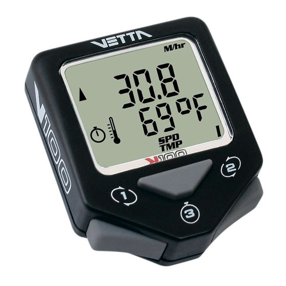
V100 ILLUSTRATIONS HEAD UNIT: FRONT Main Display Upper Display Lower Display Lower Screen Symbols Temperature Icon Service Timer Icon Stopwatch Icon Speed Comparator Symbol Upper Screen Symbols Button #1 (Left) Button #2 (Right) Button #3 (Center)
-
Page 5: Component Illustrations
HEAD UNIT: REAR Contact Pins Battery Compartment Battery Cover COMPONENT ILLUSTRATIONS…
-
Page 6
Wired Mounting Bracket Mounting Bracket Pad Riser Handle Bar Bracket Pad (You may choose B or C according to the style of your bicycle handlebar.) Spoke Magnet Spacer Wired Speed Sensor Wireless Active Mount WL Wireless Speed Transmitter Transmitter Mounting Pad Wired Cadence Sensor* Cadence Magnet* CR2032 3V Battery… -
Page 7: Button Functions
BUTTON FUNCTIONS Button #1 Button #2 Button #3 SETUP MODE Button #1 Sets digits or units and advances to the next item or screen. Button #2 Advances digits and toggles through units. Hold for fast advance. Button #3 Has no function in Initial Setup. OPERATING MODE Scrolls through lower level screen symbols and Button #1…
-
Page 8: V100 Screen Display Sequence: Bi-Level Memory
#1 and #2 simultaneously for 2 seconds. V100 SCREEN DISPLAY SEQUENCE: BI-LEVEL MEMORY The V100 series computers are programmed with a Bi-Level Memory which returns to the last screen function accessed between the upper and lower screen modes. See illustration for this sequence and…
-
Page 9
LOWER SCREEN UPPER SCREEN MODES MODES BI-LEVEL MEMORY SPD* *(optional) -
Page 10: V100 Primary Functions
V100 PRIMARY FUNCTIONS UPPER SCREEN MODES SPEED TRIP DISTANCE SPD displays the current Speed and is updated continuously. DST displays current Trip Distance. Automatically resets after the maximum trip distance (999.9) is achieved. Trip Distance is displayed in the SPD/DST screen mode and starts automatically when the wheel rotates and TT timer is active.
-
Page 11: Average Speed Maximum Speed
Note: Whenever TT is activated, the stopwatch icon appears; otherwise, it does not display. CAUTION : If RT and T T timers are not 0:00:00 and you have stopped them manually, then they MUST be restarted manually by pressing Button #3 in RT/TT mode. If not, the computer will not record speed or other ride data.
-
Page 12: Lower Screen Modes
LOWER SCREEN MODES CLOCK ODOMETER The time is displayed in the CLK/ODO screen mode and features a user selectable 12 or 24 hour format. Odometer displays cumu-lative distance until an All Clear Total Reset is performed, the battery is changed*, or the ride distance exceeds the maximum limit, after which the Odometer will automatically reset to zero.
-
Page 13: Stopwatch Intermediate Distance
Stopwatch and IDS to zero by pressing Button #3 for 2 seconds. DUAL BIKE MEMORY The V100 can be calibrated for two bicycles. It will store separate Wheel Size and Service Timer settings, Odometer settings and formats selected for Time, Temperature, Speed and Distance.
-
Page 14: V100 Secondary Functions & Features
Suspension forks, rear shocks, chains, etc. require service at specific time intervals set by manufacturers. Vetta’s Service Timer allows the rider to preset an exact number of riding hours during Setup, then signals (slow, flashing wrench icon) when the service time limit has been reached.
-
Page 15: Average Cadence* Maximum Cadence
AVERAGE CADENCE* AVG CAD MAXIMUM CADENCE* MAX CAD The V100 displays both Average and Maximum Cadence in a secondary screen. Press and hold Button #1 in the SPD/CAD screen mode for 2 seconds. Average and Maximum Cadence appear on the upper and lower lines respectively.
-
Page 16: Freeze Frame Memory
). AUTO START If the RT/TT timers read zero (0:00:00), the Vetta V100 computer automatically starts as soon as it receives input from the wheel. The RT and TT timers are activated and other ride data begins to accumulate (SPD, DST, AVG &…
-
Page 17: Sleep Mode
To conserve battery life, the V100 computer is programmed to enter a Sleep Mode after receiving no input from buttons, wheel motion or cadence for 5 minutes. In this mode, the V100 screen displays only the time of day. The computer exits Sleep Mode automatically when…
-
Page 18: Battery Installation
BATTERY INSTALLATION HEAD UNIT The V100 head unit uses a CR2032 3V lithium button cell battery. IMPORTANT: Most cycle computer problems are caused by weak or dead batteries. See the Troubleshooting section near the end of this manual for details.
-
Page 19: Wl Wireless Speed Transmitter
WL WIRELESS SPEED TRANSMITTER The V100 WL wireless speed transmitter uses an A23 12V battery. Remove cap, install battery with positive (+) side up, replace battery cap.
-
Page 20: Setup Mode & Programming
Setup screen. Note: When programming a second bike in Setup, scroll to “II” , select it, and advance as instructed above. The V100 computer will retain the values and settings entered for Bike II independently of Bike I.
-
Page 21
WHEEL SIZE CALCULATION The circumference of the wheel is measured and entered in millimeters. Bike I and II wheel sizes are set independently, and both default to 2074mm (700c x 20 or 26 x 2.0). The following chart lists the circumference measurements for the most common wheel sizes. -
Page 22
SETUP: WHEEL CIRCUMFERENCE After the bike number is selected and the display advances to the Wheel Size Setup screen, “circ” appears in small letters on the lower level and the default numbers 2074 appear on the upper level with the right digit “4”… -
Page 23
SETUP: SERVICE TIMER The Service Timers, one for each bike, may be programmed with a select number of ride time hours as the interval for servicing the bicycle or any component on it, such as a front or rear shock. Accumulated Ride Time is displayed on the upper line and the Service Time interval is set and displayed on the lower line. -
Page 24
To stop the Service Timer icon from flashing: A) Reset the • accumulated Ride Time hours (upper line) to zero “0” through the NOM Setup sequence. The Service Timer interval may also be reprogrammed at this point. B) Change TT setting to a number larger than accumulated RT. -
Page 25
“C». Then press Button #1 to select and advance. SETUP: CLOCK The V100 clock displays time in either a 12 or 24 hour format. A «PM» indicator appears only in the 12hr format. To select a format and set the… -
Page 26
SETUP: ODOMETER Bike I and Bike II have separate odometers. On a new computer the Odometer screen should read “00000” for both. To confirm this initial zero setting, simply press Button #1 successively to select each flashing digit and advance to System Check. -
Page 27: Installation Wired Model Installation
Note: System Check is activated in two ways: 1) By pressing Button #3 any time during NOM Setup and 2) Automatically at the end of either Initial or NOM Setup. To exit NOM System Check manually and enter Normal Operating Mode, press Button #3 to return to the SPD/DST primary screen mode.
-
Page 28
alignment mark on the sensor. (Fig. 1, 2) Step 3: Attach the alignment setup spacer to the magnet temporarily. (Fig. 3) Step 4: Slide and rotate the sensor until the alignment mark just touches the spacer tip on the magnet. (Fig. 4) Step 5: Route the sensor wire up the fork blade and secure it with the tape. -
Page 29
Fig. 1 Fig. 2 Spoke Zip Tie Magnet Magnet Sweep Path Spoke Magnet Spoke Wired Speed Fork Leg Sensor… -
Page 30
Fig. 3 Spoke Magnet Spoke Spacer Fig. 4 Spacer Alignment Mark Fig. 5 Spoke Magnet Wired Speed Sensor… -
Page 31: Mounting Bracket
MOUNTING BRACKET Head Unit Wired Mounting Bracket Zip Tie Mounting Pad Handlebar Fig. 6 Step 1: Install mounting pad and wired mounting bracket to the handlebar using the 2 zip ties provided. (Fig. 6) Step 2: Tighten the zip ties so that the mounting bracket holds its position on the bars yet can be easily adjusted.
-
Page 32: Head Unit
Zip Tie Handlebar HEAD UNIT The V100 head unit is designed to slide into the mounting bracket from the front to the back and lock into position. You should hear an audible “CLICK” when the head unit has been properly locked into position. This indicates proper alignment between the computer head pins and the mounting bracket contacts.
-
Page 33: Wireless Model Installation Speed Transmitter & Magnet
NOTE: WL2X Double wireless Speed & Cadence is optional. Please refer to WIRED SPEED AND CADENCE/WL2X DOUBLE The V100 is designed to operate as a wireless unit with the installation of a special active mount and WL wireless speed transmitter.
-
Page 34
Fig. 9 Fig. 10 Magnet Sweep Path Zip Ties Spoke Magnet Fork Leg Spoke Magnet Spoke… -
Page 35
Fig. 11 Spoke Magnet Spacer Spoke Fig. 12 Alignment Mark Spacer Fig. 13 Spoke Magnet WL Wireless Speed Transmitter… -
Page 36: Active Mount
ACTIVE MOUNT Attach the active mount and mounting pad to the handlebar. Adjust its position to your liking and tighten the zip ties. CAUTION: Do not over tighten the zip ties on the active mount because this may bend the bracket and affect the operation of the computer.
-
Page 37
Fig. 15 Head Unit Mounting Pad Handlebar Wireless Active Zip Tie Mount… -
Page 38: Head Unit
HEAD UNIT The head unit is designed to slide into the wireless active mount from the front to the back and lock into position. You should hear an audible “CLICK” when the head unit has been properly locked into position. This indicates proper alignment between the computer head pins and the active mount contacts.
-
Page 39: Installation Tests
If these checks do not solve the problem, talk to an Authorized Vetta Retailer or connect to www.vetta.com. IMPORTANT: Following the installation tests above, make sure that the spoke magnet locking screw and all zip ties are properly tightened.
-
Page 40
• Current speed reading is erratic or does not appear. Inspect the wiring for any breaks or kinks. Replace the mounting bracket and sensor as needed. • Incorrect data appears on screen during operation. Accuracy of the Setup data may be a problem (wheel circumference setting, bike #, etc.). -
Page 41: Technical Specifications
TECHNICAL SPECIFICATIONS TECHNICAL SPECIFICATIONS Current Speed (SPD) 0.0~120.0 KM/hr; 0.0~75.0 Mi/hr; +/-0.1 KM/hr or Mi/hr. Updated once per second. Average Speed (AVG) 0.0~120.0 KM/hr; 0.0~75.0 Mi/hr; +/-0.1 KM/hr or Mi/hr. Updated once every 0.1 Miles or Km traveled. Limit: 120.0 KM/hr; 75.0 Mi/hr. Maximum Speed (MAX) Odometer (ODO) 0~99999 km or miles.
-
Page 42
Limit: 1~1999 hrs. max; +/-1 hr. Service Timer Limit: 9:59:59 (10 hrs.); +/-1.0 seconds. Stopwatch Range: 999.9 km or miles. Intermediate Distance (IDS) Limit: 9:59:59 (10 hours) displayed in Ride/Total Time (RT/TT) hr/min/sec. After 9:59:59, display restarts at «0:00:00». Range: 15~255 RPM; +/-1 RPM. Cadence (RPM) (optional) Head Unit: CR2032 3 volt battery. -
Page 43: Warranty Policy
God, improper installation or product alteration. This warranty is void if the components were not purchased (new) from or through an authorized VETTA retailer or dealer; examples of unauthorized dealers are online auction sites or online retailers that do not offer service.
-
Page 44: Items To Be Included In Returns
The original owner may possess other rights or recourse, depending on the state or country. Please check the web to help answer any question and service manual. Acumen Inc. 101A Executive Dr., Suite 100, Sterling, VA 20166, USA. E-Mail: customerservice@vetta.com Website: www.vetta.com…
По г. Москве в пределах МКАД
Стоимость доставки составляет 340 р. за одну единицу товара. Доставка производится в пределах МКАД, а также в район Куркино и г. Химки. Доставка осуществляется до вашего подъезда. Максимальный срок доставки 3 рабочих дня со дня оформления заказа (зависит от загрузки службы доставки). Доставка осуществляется в будние дни с 10.00 до 22.00. Накануне доставки курьер свяжется с вами и сообщит о доставке.
В целях безопасности мы осуществляем доставку заказа только на конкретный адрес и не передаём товар на автостоянках, станциях метро и в других общественных местах.
Перед доставкой каждый велосипед собирается и тщательно настраивается профессиональными механиками.
Вместе с заказанным товаром покупатель получает полный комплект документов: чек, гарантийный талон, паспорт и инструкцию, в случае приобретения велосипеда.
Прием товара покупателем производится в присутствии курьера в месте достаточном для осмотра и при хорошем освещении.
К сожалению, курьер не сможет проконсультировать вас по вопросам технических параметров и функциональных особенностей товара.
Обязательно убедитесь в правильной комплектности и отсутствии дефектов товара. После получения заказа претензии к внешним дефектам товара, его количеству, комплектности и товарному виду не принимаются. В случае обнаружения брака, курьером описывается характер повреждений в соответствующем пункте акта приема-передачи, на основании которого будет произведен возврат товара.
Время ожидания покупателя курьером в месте доставки составляет не более 10 минут. В случае отсутствия покупателя в месте доставки, курьер возвращает товар в магазин.
инструкцияVetta V100 WL2X

CONTENTS
ENGLISH
INTRODUCTION
WARNINGS & CAUTIONS
V100 ILLUSTRATIONS
HEAD UNIT
COMPONENT ILLUSTRATIONS
BUTTON FUNCTIONS
SETUP MODE
OPERATING MODE
V100 SCREEN DISPLAY SEQUENCE:
BI-LEVEL MEMORY
V100 PRIMARY FUNCTIONS
UPPER SCREEN MODES
Speed,Trip Distance, Ride Time,Total Time
Average Speed, Maximum Speed,
Speed*, Cadence*
LOWER SCREEN MODES
Clock, Odometer, Speed, Temperature
Stopwatch, Intermediate Distance,
Dual Bike Memory
V100 SECONDARY FUNCTIONS
& FEATURES
Maximum & Minimum Temperature,
Service Timer
Average Cadence*, Maximum Cadence*,
Low Battery Alert, Speed Comparator
Freeze Frame Memory
1.
2.
3.
4.
5.
6.
7.
3
3
4
5
7
7
8
10
11
12
13
14
15
16
Посмотреть инструкция для Vetta V100 WL2X бесплатно. Руководство относится к категории велокомпьютеры, 1 человек(а) дали ему среднюю оценку 8.2. Руководство доступно на следующих языках: английский. У вас есть вопрос о Vetta V100 WL2X или вам нужна помощь? Задайте свой вопрос здесь
Главная
Не можете найти ответ на свой вопрос в руководстве? Вы можете найти ответ на свой вопрос ниже, в разделе часто задаваемых вопросов о Vetta V100 WL2X.
Не нашли свой вопрос? Задайте свой вопрос здесь
-
Страница 1
CONTENTS ENGLISH INTRODUCTION W ARNINGS & CAUTIONS V100 ILLUSTRA TIONS HEAD UNIT COMPONENT ILL USTRA TIONS BUTTON FUNCTIONS SETUP MODE OPERA TING MODE V100 SCREEN DISPLA Y SEQUENCE: BI-LEVEL MEMORY V100 PRIMARY FUNCTIONS UPPER SCREEN MODES Speed,T rip Distance, Ride Time,T otal Time Av erage Speed, Maximum Speed, Speed*, Cadence* LOWER SCREEN M[…]
-
Страница 2
8. 9. 10. 11. 12. 13. 16 17 17 17 18 19 20 27 31 32 33 36 38 39 39 41 43 44 AUT O ST ART SLEEP MODE RIDE DA T A RESET ALL CLEAR TOT AL RESET BATTERY INSTALLATION HEAD UNIT WL WIRELESS SPEED TRANSMIT TER SETUP MODE & PROGRAMMING INSTALLATION WIRED MODEL INST ALLA TION Speed Sensor & Magnet Mounting Bracket Head Unit WIRELESS MODEL INST ALLA […]
-
Страница 3
WARNINGS & CAUTIONS INTRODUCTION Thank you for pur chasing a Vetta V100 cycle computer . The V100 series computers represent the latest evolution in V etta’s computer line and are designed f or cycling enthusiasts and competitive cyclists alike. In par ticular , the V100 model offers a wide range of unique featur es and functions such as T[…]
-
Страница 4
V100 ILLUSTRA TIONS HEAD UNIT : FRONT A A B C D 2 7 3 1 6 5 8 4 Upper Display Lower Displa y Lower Screen S ymbols T emperature Icon Service Timer Icon Stopwatch Icon Speed Comparator Symbol Upper Screen Symbols 1 2 3 4 5 6 7 8 Main Display Button #1 (Left) Button #2 (Right) Button #3 (Center) B C D[…]
-
Страница 5
HEAD UNIT : REAR A B C C A B O P E N C L O S E C R 2 0 3 2 Contact Pins Battery Compartment Battery Cover COMPONENT ILLUSTRA TIONS B A G F D C E[…]
-
Страница 6
C R 2 0 3 2 3 V O L T L I T H I U M C E L L A B C D E F G H I J K L M N O P Wired Mounting Bracket Mounting Bracket Pad Riser Handle Bar Bracket Pad (You may choose B or C according to the style of your bicycle handlebar.) Spoke Magnet Spacer Wired Speed Sensor Wireless Active Mount WL Wireless Speed Transmitter Transmitter Mounting Pad Wired Caden[…]
-
Страница 7
Sets digits or units and advances to the next item or screen. Advances digits and t oggles through units. Hold for fast advance . Has no function in Initial Setup. Button #1 Button #2 Button #3 SETUP MODE Scrolls through lo wer level screen symbols and Freez e Frame display scr eens. Hold 2 seconds in T emperature mode (SPD/TMP) to display Maximum […]
-
Страница 8
Starts and stops the timers and Stopwatch and is used to reset timers and other ride data to zero . Exits Normal Operating Mode (NOM) Setup and advances t o NOM System Check and SPD/DST screen mode. Note: T o enter Setup in the Normal Operating Mode: 1. Make sure the timers are turned off . 2. Go to SPD/DST screen mode. 3. Press and hold Buttons #1[…]
-
Страница 9
1 2 LOWER SCREEN MODES UPPER SCREEN MODES 1 1 STP IDS CLK ODO SPD TMP 2 2 2 RT TT AV G MAX SPD DST BI-LEVEL MEMORY 1 2 SPD* CAD 2 *(optional) 1[…]
-
Страница 10
V100 PRIMARY FUNCTIONS UPPER SCREEN MODES SPD displays the current Speed and is updated continuously . DST displays current T rip Distance. Automatically r esets after the maximum trip distance (999.9) is achieved. T rip Distance is displayed in the SPD/DST screen mode and starts automatically when the wheel rotates and T T timer is active. Reset D[…]
-
Страница 11
AV G MAX A verage and Maximum Speed readings are displayed simultaneously in the A VG/MAX screen mode. Av erage Speed is updated every 0.1 miles or Km traveled . Reset both to zero by pressing Button #3 for 2 seconds with timers turned off in any scr een mode ex cept STP/IDS. A VERAGE SPEED MAXIMUM SPEED SPD CAD When installed, the Cadence kit Meas[…]
-
Страница 12
LOWER SCREEN MODES The time is displayed in the CLK/ODO screen mode and features a user selectable 12 or 24 hour format. The Odometer displays cumu-lative distance until an All Clear T otal Reset is performed, the batter y is changed*, or the ride distance exceeds the maximum limit , after which the Odometer will automatically reset to zero . *Note[…]
-
Страница 13
The independent Stopwat ch is operated b y Button #3 in the STP/IDS screen mode. STP operates in conjunction with the RT/T T timers ( icon must be visible) and can be started or stopped b y pressing Butt on #3. The Intermediate Distance function tracks an intermediate distance within a ride. IDS does not affect overall T r ip Distanc e or current r[…]
-
Страница 14
V100 SECONDARY FUNCTIONS & FEA TURES MAXIMUM & MINIMUM TEMPERA TURE T o displa y both the Maximum and Minimum T emperature readings , press and hold Button #1 for 2 seconds in the T emperature SPD/TMP screen mode. T o return to the primary SPD/TMP screen mode, press Button #1 again. When ride data is reset by holding Button #3 with the time[…]
-
Страница 15
A VERAGE CADENCE* A VG CAD MAXIMUM CADENCE* MAX CAD The V100 displays both A verage and Maximum Cadence in a secondary screen. Press and hold Button #1 in the SPD/CAD screen mode for 2 seconds. A verage and Maximum Cadence appear on the upper and lower lines respectively . Press Button #1 again to return to the primary SPD/CAD screen. *(optional) T[…]
-
Страница 16
AUTO ST ART If the RT/T T timers read z ero (0:00:00), the V etta V100 computer automatically starts as soon as it receives input from the wheel. The RT and TT timers are ac tiv ated and other ride data begins to accumulate (SPD , DST , A VG & MAX SPD , CAD*, A VG & MAX CAD*, ODO). Note: Any time the timers are stopped manually and they are[…]
-
Страница 17
ALL CLEAR TOT AL RESET All data entered in Setup, as well as all accumulated ride data, can be cleared by performing an All Clear T otal Reset. T o clear the computer , press all three buttons simultaneously and hold for 5 seconds in any screen mode . When the computer is reset , the master screen will appear and show all L CD segments for 3 second[…]
-
Страница 18
BA TTERY INST ALLA TION The V100 head unit uses a CR2032 3V lithium button cell battery . IMPORT ANT: Most c y cle computer problems are caused by weak or dead batteries. See the T roubleshooting section near the end of this manual for details. HEAD UNIT CA UTION: T o a void damage to the battery cap , do not over tighten. Step 1: Step 2: Step 3: R[…]
-
Страница 19
A23 12V C L O S E O P E N A 2 3 1 2 V C L O S E O P E N A 2 3 1 2 V C L O S E O P E N C L O S E O P E N A 2 3 1 2 V C L O S E O P E N C L O S E O P E N The V100 WL wireless speed transmitter uses an A23 12V battery . Remove cap , install battery with positive (+) side up, replace battery cap. WL WIRELESS SPEED TRANSMITTER[…]
-
Страница 20
The screen displays the letters “bic no ” in the Initial Setup mode with Bike I as the default setting. T o toggle between Bike I and Bike II settings, press Button #2. With Bike “I” icon flashing, press Button #1 to select it and ad-vance t o the next Setup screen. Note: When programming a second bike in Setup , scroll to “II” , selec […]
-
Страница 21
Step 1: Step 2: Measure the distance from the center of the front wheel axle to the ground in millimeters. (1 inch = 25.4mm) Multiply this distance by 6.2832 (2 ± ) and enter the result as the wheel size setting into the computer . If your wheel size is not on the chart, or if you want a more precise calibration, wheel circumference ma y be calcul[…]
-
Страница 22
Step 1: Step 2: Step 3: T o enter a specific wheel siz e, press Button #2 to advance the flashing digit to the desired number . When the corr ect number is reached , select it by pr essing Button #1. The next digit to the left will star t flashing . Press Button #2 t o advance the flashing digit to the next desired number in the sequence and press […]
-
Страница 23
Step 1: Step 2: T o set a service interval (in hours only) scroll to the number you want to set using Button #2 and select it by pressing Button #1. Note: The Ser vice Timer sets and displa ys whole hours only . I t does not display minut es. Proceed until all the digits for the service interval have been selected, then press Butt on #1 again. (199[…]
-
Страница 24
T o stop the Service Timer icon from flashing: A) Reset the accumulated Ride Time hours (upper line) to zero “0” through the NOM Setup sequence. The Service Timer interval may also be reprogrammed at this point. B) Change TT setting to a number larger than accumulated RT . C) Set T T to z ero “0000” (disable the Service Timer). The Service […]
-
Страница 25
Step 1: Step 2: Step 3: Step 4: Use Button #2 to toggle betw een the two time formats (the numbers will flash). Press Button #1 to select the desired time format and advance t o the Clock Setup screen with the left hours digits flashing. T o set the current time , press Button #2 to advance the flashing digit, then press Button #1 to select it and […]
-
Страница 26
Bike I and Bike II have separate odometers . On a new computer the Odometer screen should read “00000” for both. T o confirm this initial zero setting, simply press Button #1 successively to select each flashing digit and advance to System Check. T o reenter mileage achieved after a battery change, follow these steps: SETUP: ODOMETER Step 1: St[…]
-
Страница 27
INST ALLA TION WIRED MODEL INST ALLA TION SPEED SENSOR & MAGNET Step 1: Step 2: Use the zip-tie supplied to hold loosely the wired speed sensor and mounting pad to the inside of either fork leg . W e recommend mounting it as high up on the fork leg as possible to protect it from being hit by rocks, branches or other objects while riding. (Fig. […]
-
Страница 28
Step 3: Step 4: Step 5: Step 6: Step 7: alignment mark on the sensor . (Fig. 1, 2) Attach the alignment setup spacer t o the magnet temporarily . (Fig . 3) Slide and rotate the sensor until the alignment mark just touches the spacer tip on the magnet. (Fig. 4) Route the sensor wire up the fork blade and secure it with the tape. Wrap excess wire ar […]
-
Страница 29
Fig. 1 Fig. 2 Wired Speed Sensor Fork Leg Spoke Magnet Spoke Magnet Spoke Magnet Sweep Path Zip Tie[…]
-
Страница 30
Fig. 4 Spacer Tip Alignment Mark Spacer Fig. 3 Spoke Magnet Spoke Fig. 5 Wired Speed Sensor Spoke Magnet[…]
-
Страница 31
Step 1: Step 2: Install mounting pad and wired mounting bracket to the handlebar using the 2 zip ties provided . (F ig. 6) Tighten the zip ties so that the mounting bracket holds its position on the bars yet can be easily adjusted . (Fig. 7 ) T rim excess. CAUTION: Do not use zip ties but tapes provided to hold wires to the frame, fork, bars or ste[…]
-
Страница 32
HEAD UNIT The V100 head unit is designed to slide into the mounting bracket from the front to the back and lock into position. Y ou should hear an audible “CLICK” when the head unit has been properly locked into position . This indicates proper alignment between the c omputer head pins and the mounting bracket contacts. T o remove the computer […]
-
Страница 33
WIRELESS MODEL INST ALLA TION SPEED TRANSMITTER & MAGNET The V100 is designed to operate as a wireless unit with the installation of a special active mount and WL wireless speed transmitter . Step 1: Step 2: Step 3: Step 4: Step 5: Step 6: Use the zip-ties supplied to hold loosely the WL wireless speed transmitter and mounting pad to the left f[…]
-
Страница 34
Fig. 9 Spoke Magnet UP Fork Leg Zip Ties A 2 3 C L O S E O P E N C L O S E O P E N Magnet Sweep Path Spoke Magnet Spoke Fig. 10[…]
-
Страница 35
A 2 3 C L O S E O P E N C L O S E O P E N Alignment Mark Spacer Tip Fig . 12 A 2 3 C L O S E O P E N C L O S E O P E N Spoke Magnet WL Wireless Speed T ransmitter Fig . 13 Spacer Spoke Magnet Spoke Fig . 11[…]
-
Страница 36
Attach the active mount and mounting pad to the handlebar . Adjust its position to your liking and tighten the zip ties. CA UTION: Do not o ver tighten the zip ties on the active mount because this may bend the bracket and affect the operation of the computer . (Fig . 14, 15) ACTIVE MOUNT Wireless Active Mount Head Unit Zip Tie Mounting Pad Handleb[…]
-
Страница 37
Head Unit Mounting Pad Handlebar Wireless Active Mount Zip Tie Fig . 15[…]
-
Страница 38
Wireless Active Mount Locking Ta b Locking Ta b Head Unit UNL OCK UNL OCK OUT IN Fig . 16 HEAD UNIT The head unit is designed to slide into the wireless active mount from the front to the back and lock into position . Y ou should hear an audible “CLICK” when the head unit has been proper ly locke d into position. This indicates proper alignment[…]
-
Страница 39
INST ALLA TION TESTS Once installation is complete , the computer should be tested t o make sure it is working properly . If there is no speed reading, make sure the timers (RT/T T ) are running, check the alignment and spacing between the magnet and sensor/transmitter and make sure that the head unit is completely snapped into position. If these c[…]
-
Страница 40
• Curren t speed reading is erratic or does not appear . Inspec t the wiring f or any breaks or kinks. Replace the mounting bracket and sensor as needed. • Incorrect data appears on screen during opera tion. Accuracy of the Setup data may be a problem (wheel circumference setting , bik e #, etc.). Review data in System Check mode and revise as […]
-
Страница 41
Current Speed (SPD) A verage Speed (A VG) Maximum Speed (MAX) Odometer (ODO) T rip Distance (DST) T emperature ( TMP) Clock (CLK) 0.0~120.0 KM/hr; 0.0~75.0 Mi/hr ; +/-0.1 KM/hr or Mi/hr . Updated once per second. 0.0~120.0 KM/hr; 0.0~75.0 Mi/hr ; +/-0.1 KM/hr or Mi/hr . Updated once every 0.1 Miles or Km traveled. Limit: 120.0 KM/hr ; 75.0 Mi/hr. 0[…]
-
Страница 42
Service Timer Stopwatch Intermediate Distance (IDS) Ride/T otal Time (RT/T T) Cadence (RPM) (optional) Po wer Supply Battery Life Limit: 1~1999 hrs. max; +/-1 hr . Limit: 9:59:59 (10 hrs.); +/-1.0 seconds. Range: 999.9 km or miles. Limit: 9:59:59 (10 hours) displayed in hr/min/sec. After 9:59:59, display restarts at «0:00:00». Range: 15~2[…]
-
Страница 43
WARRANTY POLICY ACUMEN INC. WARRANTS ALL VETTA (The Company) PRODUCTS AGAINST MANUFACTURER DEFECTS FOR A PERIOD OF 3 YEARS. Subject to the following limitations, terms and conditions, components will be free of manufacturing defects in materials and workmanship. The 3 year limited warranty is conditioned upon the components being used and operated […]
-
Страница 44
I TEMS TO BE INCLUDED IN RETURNS 1. The defective product(s) 2. A letter clearly stating the problem(s) with the returned item(s). 3. Copy of the original sales receipt showing proof of purchase date. 4. The Company is not responsible for loss or additional damages while in transit to ACUMEN INC. 5. Clearly mark the RA# on the outside of the return[…]

- Форум
- Техника
- Технические вопросы
- Электроника
- Велокомпьютер VETTA V 100. Где взять инструкцию на русском языке?

-
22.04.2012, 19:07
#1
Веломаньяк
Велокомпьютер VETTA V 100. Где взять инструкцию на русском языке?
Купил и установил велокомпьютер VETTA V 100, а инструкции на русском языке нет. Где можно ее взять, подскажите пожалуйста?
-
24.04.2012, 20:16
#2
Без 5-ти минут веломаньяк!
Сообщение от Мэр Простоквашино
Купил и установил велокомпьютер VETTA V 100, а инструкции на русском языке нет. Где можно ее взять, подскажите пожалуйста?
Как пример:
http://www.scribd.com/doc/47569068/vetta-V100-manual
использовать функцию «перевести» на панели инструментов Google.
Либо скачать pdf файл, конвертировать в docx. и перевести при помощи онлайн переводчика.
Удачи!
-
24.04.2012, 20:34
#3
Зобанен
Последний раз редактировалось Микола; 24.04.2012 в 20:37.


")
Информация о теме
Пользователи, просматривающие эту тему
Эту тему просматривают: 1 (пользователей: 0 , гостей: 1)
Похожие темы
-
Ответов: 17
Последнее сообщение: 24.02.2007, 18:30
-
Ответов: 8
Последнее сообщение: 21.06.2006, 15:57
-
Ответов: 3
Последнее сообщение: 12.12.2005, 13:57
-
Ответов: 0
Последнее сообщение: 04.06.2005, 12:56
-
Ответов: 3
Последнее сообщение: 02.06.2005, 16:09