-
Contents
-
Table of Contents
-
Bookmarks
Quick Links
VIESMANN
Operating instructions
for the system user
Heating system with weather-compensated control unit
Vitotronic 200, type KO1B, KO2B or KW6B
VITOTRONIC 200
Please keep safe.
5592667 GB
3/2018
Related Manuals for Viessmann Vitotronic 200 Series
Summary of Contents for Viessmann Vitotronic 200 Series
-
Page 1: Operating Instructions
VIESMANN Operating instructions for the system user Heating system with weather-compensated control unit Vitotronic 200, type KO1B, KO2B or KW6B VITOTRONIC 200 Please keep safe. 5592667 GB 3/2018…
-
Page 2: Safety Instructions
Safety instructions For your safety Please follow these safety instructions closely to prevent accidents and material losses. Safety instructions explained Danger Note This symbol warns against the risk of injury. Details identified by the word «Note» contain additional information. Please note This symbol warns against the risk of material losses and environmental pollution.
-
Page 3
Safety instructions For your safety (cont.) If you smell gas Danger Escaping gas can lead to explosions which may result in serious injury. ■ Never smoke. Prevent naked flames and sparks. Never switch lights or electrical appli- ances on or off. Close the gas shut-off valve. -
Page 4
Safety instructions For your safety (cont.) Installation room requirements Danger Please note Sealed vents result in a lack of combustion air. Incorrect ambient conditions can lead to heating This leads to incomplete combustion and the system damage and can put safe operation at formation of life threatening carbon monoxide. -
Page 5: Table Of Contents
Index Index 1. Information Symbols ………………..2. Introductory information Intended use ………………Commissioning ………………Terminology ………………. Your system is preset at the factory …………Energy saving tips …………….. Tips for more comfort …………….3. Operation Opening the control unit …………….. 10 Programming unit ………………
-
Page 6
Index Index (cont.) Setting the display brightness …………..30 Entering names for the heating circuits ……….30 Setting the preferred heating circuit for the standard menu ….31 Setting the time and date …………… 31 Language selection …………….31 Setting the temperature unit (°C/°F) …………31 Restoring factory settings ………….. -
Page 7: Symbols
Information Symbols Symbol Meaning Reference to other document containing further information Step in a diagram: The numbers correspond to the order in which the steps are carried out. Warning of material losses and environ- mental pollution Live electrical area Pay particular attention. Component must audibly click into place.
-
Page 8: Intended Use
Introductory information Intended use The appliance is intended solely for installation and Any usage beyond this must be approved by the man- operation in sealed unvented heating systems that ufacturer in each individual case. comply with EN 12828, with due attention paid to the associated installation, service and operating instruc- Incorrect usage or operation of the appliance (e.g.
-
Page 9: Energy Saving Tips
Introductory information Energy saving tips Central heating ■ Ventilation: To ventilate, close the thermostatic valves and open Standard room temperature («Set room tempera- the windows fully for a short time. ■ ture», see page 23): Roller shutters: ■ Never overheat your home. Every degree of room Close roller shutters (where installed) at dusk.
-
Page 10: Opening The Control Unit
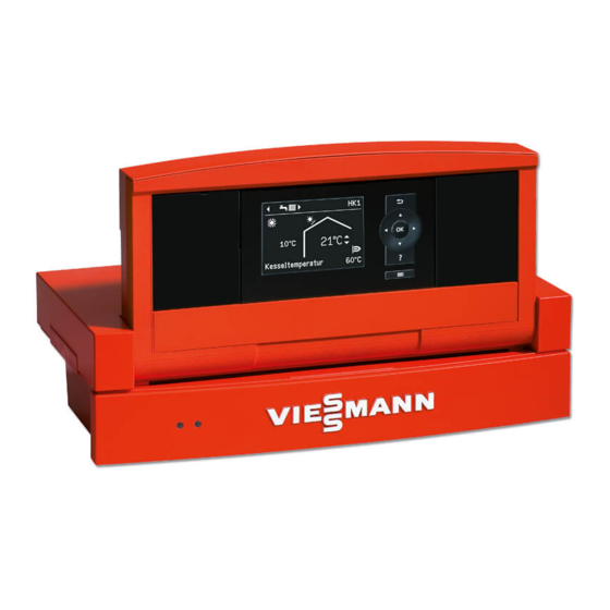
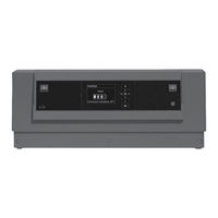
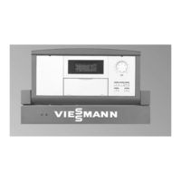
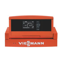
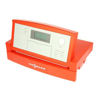
Operation Opening the control unit The control unit may look different depending on the control unit type. Vitotronic 200, type KO1B Fig. 1 Top part of control unit with programming unit Cover flap Short operating guide on the inside of the cover Vitotronic 200, type KO2B Fig.
-
Page 11: Programming Unit
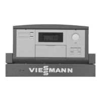
Operation Opening the control unit (cont.) Vitotronic 200, type KW6B Note You will find a short operating guide in the «Technical documentation». Fig. 3 Top part of control unit with programming unit Pushbutton for changing the angle Programming unit You can change any settings on your heating system Remote control operating instructions centrally at the programming unit of the control unit.
-
Page 12: Help» Menu
Operation Programming unit (cont.) «Help» menu Displays explanations about operation in the form of a Call up the short guide as follows: short guide. ■ If the screensaver is active (see page 14): Press . ■ From anywhere in the menu: Press repeatedly until the standard menu is shown (see page 12).
-
Page 13: Extended Menu
Operation Standard menu (cont.) Note Setting the operating program for the preferred ■ Settings for the preferred heating circuit can also be heating circuit adjusted in the extended menu (see page 13). The settings for any other connected heating circuits Press the following keys: ■…
-
Page 14
Operation How to use the controls (cont.) Screen saver 21°C 14°C Fig. 7 Current outside temperature Set room temperature 1. Press OK. This takes you to the standard menu Adjustments to the central heating can be made for (see page 12). every heating circuit. -
Page 15: How To Use The Controls
Operation How to use the controls (cont.) 21 °C 14 °C Boiler temperature 48 °C Menu Heating Solar energy Test mode Continue with Heating circuit 1 Ù Ú Htg circ. selection Ù Ú Ù Ú Party mode ê Ú Economy mode Heating circuit 2 ê…
-
Page 16: Operating Program
Operation Operating program Operating programs for central heating, DHW, frost protection Symbol Operating program Function Central heating and DHW heating «Heating and DHW» The rooms of the selected heating circuit are ■ heated in accordance with the room temperature and time program specified (see chapter «Central heating»).
-
Page 17: Time Program
Operation Time program The following explains how to input the settings for a ■ You can set the time program individually, to be the time program. The special features of each individual same, or different, for every day of the week. time program are assigned to the relevant chapters.
-
Page 18: Setting The Time Program Efficiently
Operation Time program (cont.) Setting the time program efficiently If you would like to set a different time program for just Example: You want to set a different time program for one day of the week, proceed as follows: Monday: 1.
-
Page 19
Operation Time program (cont.) Heating Mo-Fr 10 12 14 16 18 20 22 24 — -:- — — — -:- — Normal — -:- — — — -:- — Normal § Adopt with Fig. 13… -
Page 20: Starting The Heating System
Start-up/shutdown Starting the heating system Controls with the cover open For cover flap, see page 10. Vitotronic 200, type KO1B 21°C 14°C Fig. 14 Fault indicator (red) Temperature controller On indicator (green) Excess temperature reset TEST key ON/OFF switch (only for service purposes) Cover flap Vitotronic 200, type KO2B 21 °C…
-
Page 21: Shutting Down The Heating System
Start-up/shutdown Starting the heating system (cont.) Vitotronic 200, type KW6B Fig. 16 Fault indicator (red) Reset button On indicator (green) ON/OFF switch Ask your heating contractor about the following: 3. Open the shut-off valves in the oil lines (at the tank ■…
-
Page 22: Without Frost Protection Monitoring (Shutdown)
Start-up/shutdown Shutting down the heating system (cont.) Without frost protection monitoring (shutdown) 1. Turn off the ON/OFF switch (see pages 20 Information on a prolonged shutdown and 21). ■ Circulation pumps may seize up as they are not sup- plied with power. 2.
-
Page 23: Room Temperature
Central heating Room temperature Further information can be found in chapter «Terminology» in the appendix. Setting the standard room temperature for central heating Factory setting: 20 °C For all heating circuits For the preferred heating circuit Extended menu Standard menu 2.
-
Page 24: Setting The Time Program For Central Heating
Central heating Time program (cont.) Setting the time program for central heating Factory setting: One time phase from 6:00 to 22:00 h Note for every day of the week. When setting, bear in mind that your heating system requires some time to heat the rooms to the required Extended menu: temperature.
-
Page 25: Comfort Function «Party Mode
Central heating Comfort function «Party mode» Setting «Party mode» for central heating Extended menu Display in the standard menu 2. «Heating» 3. If necessary, / for the required heating circuit. 4. «Party mode» 5. Set the required room temperature for «Party mode».
-
Page 26: Cancelling «Economy Mode
Central heating Energy saving function «Economy mode» (cont.) Display in the standard menu Note The display of the set room temperature does not change. 21°C 14°C Boiler temperature 48°C Fig. 20 Cancelling «Economy mode» Automatically when the system switches to reduced ■…
-
Page 27: Cancelling Or Deleting The «Holiday Program
Central heating Energy saving function «Holiday program» (cont.) Display in the extended menu In the extended menu, you can call up the set holiday program under «Information» (see page 33). Cancelling or deleting the «Holiday program» Extended menu 3. «Holiday program» 4.
-
Page 28: Dhw Temperature
DHW heating DHW temperature Factory setting: 50 °C 3. «Set DHW temperature» 4. Set the required value. Extended menu 2. «DHW» Operating program Further information can be found in chapter «Terminology» in the appendix. Setting the operating program for DHW heating For the preferred heating circuit 3.
-
Page 29: Setting The Time Program For The Dhw Circulation Pump
DHW heating Time program (cont.) Setting the time program for the DHW circulation pump The time program for the DHW circulation pump is pre- 3. «DHW circ time prog» set to Automatic mode at the factory. In other words, 4. Set the required time phases. the DHW circulation pump operates in parallel to the To see how to set a time program, see page 17.
-
Page 30: Setting The Display Contrast
Further adjustments Setting the display contrast You can make the menu texts easier to read. To do so, 2. «Settings» adjust the contrast of the display to suit the lighting conditions in the room. 3. «Contrast» 1. Extended menu: 4. Set the required contrast. Setting the display brightness You would like to be able to read the text in the menu 2.
-
Page 31: Setting The Preferred Heating Circuit For The Standard Menu
Further adjustments Entering names for the heating circuits (cont.) The menu shows «Apartment» for «Heating circuit 2». Apartment Ù Ú Party mode 22°C Economy mode ß Set room temperature Set reduced room temp Select with Fig. 25 Setting the preferred heating circuit for the standard menu If your heating system has several heating circuits, Extended menu you can select the heating circuit to be displayed in the…
-
Page 32: Restoring Factory Settings
Further adjustments Setting the temperature unit (°C/°F) (cont.) 2. «Settings» 4. Select the temperature unit «°C» or «°F». 3. «Temperature unit» Restoring factory settings You can reset the factory settings of all modified values 3. «Standard setting» for each heating circuit separately. 4.
-
Page 33: Scanning Information
Scanning Scanning information Subject to the components connected and the settings Solar energy made, you can scan current temperatures and operat- ing conditions. In the extended menu, information is split into groups: ■ «General» ■ «Heating circuit 1» Su Mo ■…
-
Page 34
Scanning Scanning the service messages (cont.) 1. You can call up the reason for the service with OK. Note If the service cannot be carried out until a later date, Service the service message will be displayed again the follow- ing Monday. -
Page 35: Scanning Fault Messages
Scanning Scanning fault messages If any faults have occurred in your heating system, the 3. Make a note of the cause of the fault and the fault symbol flashes on the display and «Fault» is shown. code next to it on the right. In the example: «Out- The red fault indicator flashes (see chapter «Starting side t sens 18″…
-
Page 36: Emissions Test Mode
Emissions test mode Emissions test mode Emissions test mode for testing flue gas with briefly Note raised boiler water temperature. The flue gas inspector can also enable emissions test Emissions test mode should only be activated by your mode if the controls are locked out by your heating flue gas inspector during the annual inspection.
-
Page 37: Rooms Are Too Cold
What to do if… Rooms are too cold Cause Remedy The heating system is off. Turn on the ON/OFF switch (see diagrams from ■ page 20). Switch ON the mains isolator (if installed, outside the ■ boiler room). Reset the MCB in the power distribution board (main ■…
-
Page 38: Rooms Are Too Hot
What to do if… Rooms are too cold (cont.) Cause Remedy Vitoair draught stabiliser faulty. Contact your local heating contractor. Press the rotary selector on the motor and turn it past position as far as it will go. Mixer motor faulty. Adjust the mixer manually.
-
Page 39: Controls Locked Out» Is Displayed
What to do if… There is no hot water (cont.) Cause Remedy Vitoair draught stabiliser faulty. Contact your local heating contractor. Press the rotary selector on the motor and turn it past position as far as it will go. «Fault» is displayed, and the red fault indicator flashes. Call up and acknowledge the type of fault (see page 35).
-
Page 40: External Program» Is Displayed
What to do if… «External program» is displayed Cause Remedy The operating program set at the control unit was You can change the operating program. changed over by the Vitocom communication interface.
-
Page 41
If there is damage to the connecting cables or lines of the appliance or externally installed accessories, these must be replaced with special cables or lines. Only use Viessmann cables / lines as replacement. For this, notify your qualified contractor. -
Page 42: Fuel Oil Quality
Biofuels Biofuels are made from vegetable oil, e.g. sunflower or Please note rape seed oil. Biofuels can lead to damage on Viessmann oil burners. With boilers built in or after 2012, up to 10 % added bio-components (FAME) are generally allowed.
-
Page 43: Overview Of Extended Menu
Appendix Overview of extended menu Fig. 36 Calling up options under «Information» Note «Burner stage 1» Subject to the actual heating system equipment level, «Hours run» not all of the scans listed here may be available. «Burner stage 2» Where information is marked with , you can call up further details.
-
Page 44: Terminology
Appendix Calling up options under «Information» (cont.) «Date» «Time program» «Radio clock signal» «Set room temp» «Room temperature» Heating circuit 1 (HC1) «Set red. room temp» «Heating program» «Set ext. room temp» «External hook-up» ■ «Set party temp» «Holiday program» ■…
-
Page 45
Appendix Terminology (cont.) Mixer extension kit Room temperature-dependent heating mode Assembly (accessory) for controlling a heating circuit With room temperature-dependent operation a room with mixer. will be heated until the selected set room temperature See «Mixer». has been reached. A separate temperature sensor must be installed in the room for this purpose. -
Page 46
Appendix Terminology (cont.) Slope -5 -10 -15 -20 Outside temperature in °C Fig. 37 For outside temperature 14 °C: − Underfloor heating system, slope 0.2 to 0.8 Low temperature heating system, slope 0.8 to 1.6 Heating system with a boiler water temperature in excess of 75 °C, slope 1.6 to 2.0… -
Page 47
Appendix Terminology (cont.) Factory settings: Slope = 1.4 and level = 0. Outside temperature in °C Fig. 38 Changing the slope: The gradient of the heating curves changes. Changing the level: The heating curves are shifted in parallel in a verti- cal direction. -
Page 48: Information On Disposal
(Altstoff Recycling Austria AG, licence num- ber 5766). Final decommissioning and disposal of the heating system Viessmann products can be recycled. Components DE: Operating fluids (e.g. heat transfer medium) can and fluids from your heating systems are not part of be disposed of at municipal collection points.
-
Page 49: Keyword Index
Keyword index Keyword index Additives for fuel oil………… 42 Economy mode – Cancelling…………… 26 – Central heating…………25 Biofuels…………..42 – Symbol…………..12 Emissions test mode……….36 Energy saving (tips)…………. 9 Central heating Energy saving function – Factory setting…………8 – Economy mode, central heating……25 –…
-
Page 50
Keyword index Keyword index (cont.) Rooms Language selection………… 31 – Too cold…………..37 Level, heating curve……….. 24 – Too hot…………..38 Room temperature – Energy saving…………9 Maintenance……………41 – For reduced heating mode……..23 Maintenance contract……….41 – Preferred heating circuit………. 13 Menu –… -
Page 51
Keyword index Keyword index (cont.) Starting Time program – Frost protection monitoring……..21 – Central heating…………24 – Heating system…………20 – Comfort…………..9 – Standby mode…………21 – DHW circulation pump……….29 Starting the appliance……….21 – DHW heating…………28 Summertime changeover……….8 –… -
Page 52
Your contact Contact your local contractor if you have any questions about your system or wish to arrange maintenance or repair work. You can find local contractors on the internet at www.viessmann.de. Viessmann Werke GmbH & Co. KG Viessmann Limited…
- Manuals
- Brands
- Viessmann Manuals
- Boiler
- VITOTRONIC 200
Manuals and User Guides for Viessmann VITOTRONIC 200. We have 18 Viessmann VITOTRONIC 200 manuals available for free PDF download: Service Instructions Manual, Installation And Service Instructions For Contractors, Installation And Service Instructions Manual, Operating Instructions Manual, Operating Instructions For The System User, Technical Data Manual, Quick Reference Manual, Quick Start Programming Manual

Viessmann VITOTRONIC 200 Service Instructions Manual (336 pages)
Heat pump control unit
Brand: Viessmann
|
Category: Control Unit
|
Size: 7.87 MB
Table of Contents
-
Index Index
4
-
Table of Contents
4
-
-
Introduction Scope of Functions
16
-
Version
17
-
Sion
20
-
Refrigerant Circuit Controller
23
-
Setting Levels
24
-
Programming Unit
25
-
Primary Source, Ice Store/Solar
26
-
Operation with External Heat Generator (Not for Compact Appliances)
27
-
Heating Water Buffer Cylinder
28
-
Switching on the Compressor
28
-
-
Heat Pump Cascade
29
-
Central Cooling
30
-
Central Heating
30
-
DHW Heating
30
-
Integrating a Heat Pump Control Unit into LON
30
-
Swimming Pool Heating
30
-
Calling up Heat Pumps
31
-
Shutting down Heat Pumps
32
-
-
External Hook-Up for Heating/Cooling Circuits
33
-
Signal Effects
34
-
-
Smart Grid
35
-
Connection to Heat Pump Control Unit
36
-
-
Booster Heaters
37
-
External Heat Generator
38
-
Instantaneous Heating Water Heater
39
-
DHW Heating
40
-
DHW Reheating with Booster Heaters
42
-
Solar DHW Heating
43
-
Overview of Buffer Cylinders
44
-
Buffer Cylinder in Conjunction with Heat Pump Cascade
45
-
Heating the Buffer Cylinder with Booster Heaters
46
-
Frost Protection
47
-
-
Heating Circuits/Cooling Circuits
48
-
Weather-Compensated Control
50
-
Room Temperature-Dependent Control
51
-
Starting Central Heating
52
-
Deactivating Central Cooling
53
-
Central Heating with Booster Heaters
54
-
-
Natural Cooling Function (NC)
55
-
System with Heating Water/Coolant Buffer Cylinder
56
-
Connections at EA1 Extension
57
-
-
Mechanical Ventilation with Vitovent 200-C/300-F
58
-
Passive Heating
59
-
Passive Cooling
60
-
Vitovent 200-C: Frost Protection
61
-
Vitovent 300-F: Frost Protection
63
-
Protection against Excessively High Temperatures
64
-
-
Mechanical Ventilation with Vitovent 200-W/300-C/300-W
65
-
Passive Cooling
66
-
Cooling Via Geothermal Heat Exchanger
67
-
Protection against Excessively High Temperatures
68
-
-
Photovoltaics
69
-
Enabling Utilisation of Power Generated on Site
70
-
Buffer Cylinder Heating
71
-
Cooling the Heating Water/Coolant Buffer Cylinder
72
-
Troubleshooting Overview
74
-
-
Message Overview
75
-
Elec. Heating Blocked
77
-
Refrigerant Circuit
78
-
Outside Temp. Sensor
79
-
Flow Sensor Secondary
80
-
Flow Sensor Primary
81
-
Hot Gas Temp Sensor 2
82
-
Flow Sensor HC2
83
-
Flow Sensor HC3
84
-
Cylinder Sensor Top
85
-
Buffer Outlet Temp
86
-
Room Temp. Sensor HC1
87
-
Room Temp. Sensor HC1
88
-
Solar Module Sensor 10
89
-
C Cylinder Sensor Solar
90
-
A2 Compressor 2
91
-
A8 Heating Circ. Pump HC1
92
-
AA Cancel Defrost
93
-
AD Mixer Heating/Dhw
94
-
B4 AD Converter
95
-
C2 Power Supply
96
-
CA Protectn Device Primry
97
-
CB Flow Temp. Primary
98
-
D3 Low Pressure
99
-
D5 Contact Humidistat
100
-
D6 Flow Switch
101
-
E6 Fault at LON Subscbr
102
-
Diagnosis Diagnosis (Service Scans)
104
-
System Overview
110
-
-
System
120
-
Integrals
121
-
Logbook
123
-
-
Ventilation
128
-
Ventilation
130
-
Message History Vitovent 200-C/300-F
132
-
Vitovent 200-W/300-C/300-W Message History
135
-
-
Heat Pump
136
-
Refrigerant Circuit
137
-
Compressor Travel
146
-
Compressor Path
147
-
Message History [2]
148
-
Message History [4]
153
-
Message History [4-6] / [4-7]
164
-
Message History [6]
172
-
-
Energy Statement
178
-
Calling up the Energy Statement
179
-
Photovoltaics
180
-
DHW Loading Statistics
181
-
Output Curves
182
-
System Information
183
-
-
Actuator Test (Testing Outputs)
185
-
LON Subscriber Check
187
-
Enter Vitocom PIN Code
188
-
Saving/Loading Settings
192
-
-
Coding Level 1 in the Service Menu
193
-
-
Temperature
194
-
Setting Parameters
194
-
Restoring Delivered Condition (Reset)
195
-
Calling up the Parameter Group
196
-
-
Interval for Long Term Average Outside Temperature
197
-
Temperature Differential for Calculating the Cooling Limit
198
-
Swimming Pool
199
-
External Extension
200
-
Bit
201
-
Fig. 53
201
-
-
Operating Status for External Changeover
201
-
Heating Circuit Without Mixer
202
-
-
Effect of External Demand on Heat Pump/Heating Circuits
202
-
Vitocom 100
203
-
Bit
204
-
-
B Common Flow Temperature Sensor System
204
-
Number of Lag Heat Pumps
205
-
Minimum Temp. for Solar Absorber Primary Source
206
-
Absorber Circuit Monitoring
207
-
Bit
208
-
-
Holiday Program Effect
208
-
Evaporator Temperature for Defrost End
209
-
Output Compressor Stage
210
-
B01 Priority Ext. Heat Source/Instant. Heating Water Heater
211
-
B03 Start Threshold External Heat Source
212
-
B07 Run-On Time External Heat Source
213
-
B0E Dual Mode Heat Pump Operation
214
-
B11 Enable Boiler Water Temperature Sensor
215
-
Parameter Group DHW Calling up the Parameter Group
216
-
-
Hysteresis DHW Temperature Heat Pump
217
-
Start Optimisation for DHW Heating
218
-
E Temperature Sensor at Bottom of DHW Cylinder
219
-
Enable Electric Heaters for DHW Heating
220
-
F Cylinder Primary Pump Enable
221
-
Max. Interruption DHW Heating
222
-
Calling up the Parameter Group
223
-
Calling up the Parameter Group
224
-
Enable Instant. Heating Water Heater for Central Heating
225
-
A Output for Instant. Heating Water Heater at Power-OFF
226
-
Calling up the Parameter Group
227
-
C Flow Temperature for External Demand
228
-
D Enable 3-Way Diverter Valve Heating/Dhw
229
-
Compressor Performance at Max. Outside Temperature
230
-
Rated Output Secondary Pump (PWM)
231
-
Starting Time High Efficiency Circulation Pump
232
-
Screed Program End Day
233
-
Calling up the Parameter Group
234
-
Min. Primary Circuit Inlet Temperature in Operation
235
-
Calling up the Parameter Group
236
-
Max. Temperature Buffer Cylinder
237
-
Stop Hysteresis, Heating Water Buffer Cylinder
238
-
A Min. Temperature Coolant Buffer Cylinder
239
-
Calling up the Parameter Group
241
-
Room Temperature Control
242
-
A Influence Room Temperature Hook-Up
243
-
Room Temperature in Party Mode
244
-
Influence Room Temperature Hook-Up Cooling Circuit
245
-
Parameter Group Cooling Calling up the Parameter Group
246
-
-
Influence Room Temperature Hook-Up Cooling Circuit
247
-
Enable Flow Temperature Sensor Cooling Circuit
248
-
Dew Point Monitor
249
-
D01 Enable Preheater Bank Electric
250
-
D04 Enable Target Temperature Control
251
-
D0A Flow Rate Reduced Ventilation
252
-
D18 CO2 Value for Raising the Flow Rate
253
-
D1B Intensive Ventilation Duration
254
-
D27 Control Voltage Matching
255
-
D2F Installation Position
256
-
D71 Control Voltage Matching, Supply Air Fan
257
-
D72 Control Voltage Matching, Exhaust Air Fan
258
-
C101 Preheater Coil
259
-
C106 CO2 Sensor
260
-
C10B Standard Ventilation
261
-
C18A Reduced Ventilation, Second Fan Duct
262
-
C1A0 Bypass Mode
263
-
C1A3 Specified Imbalance
264
-
C1AA Min. Temperature, Geothermal Heat Exchanger
265
-
C1C1 Min. Voltage, Input 2
266
-
E02 Prop. of External Current
267
-
E04 Threshold for Electrical Power
268
-
E12 Enable Own Energy Consumptn for Heating Water Buffer Cyl
269
-
E21 Raise Set DHW Cylinder Temperature PV
270
-
E82 Smart Grid Enable Elec Heat
271
-
E91 Smart Grid Set Value Increase for DHW Heating
272
-
C00 to 7C06 Automatic Changeover Summertime — Wintertime
273
-
Calling up the Parameter Group
274
-
-
C Interval for Data Transfer Via LON
275
-
FF Send Time
276
-
Calling up the Parameter Group
277
-
-
Overview of the Pcbs
278
-
Heat Pumps with Separate Indoor and Outdoor Unit
279
-
-
Main and Expansion PCB
280
-
Expansion PCB on Main PCB
284
-
Connections for DHW Heating
287
-
-
Vitocal 300-A Cross Connect PCB
289
-
Luster Terminals, Vitocal 100-S/200-A/200-S
292
-
Luster Terminals, Vitocal 111-S/222-A/222-S
294
-
Luster Terminals Vitocal 200-A
296
-
Vitocal 222-G/333-G Luster Terminals
299
-
Vitocal 100-S/200-A/200-S/300-A Controller and Sensor PCB
300
-
Vitocal 111-S/222-A/222-S/222-G/333-G Controller and Sensor PCB
302
-
Inverter
305
-
Eev Pcb [4-3] / [4-4]
307
-
Eev Pcb [4-6] / [4-7]
308
-
Vitocal 222-G
309
-
Controller PCB: Type AWO 301.A25 to A60
310
-
EEV PCB: Type AWO 301.A60
311
-
Main PCB [7] / [7-1]
312
-
Jumper ID (Blue)
313
-
-
-
Temperature Sensors
314
-
Viessmann Pt500A (Green Marking)
316
-
Pressure Sensors
321
-
Declarations of Conformity for Heat Pumps
323
-
-
-
Advertisement

Viessmann VITOTRONIC 200 Service Instructions Manual (188 pages)
Vitotronic 200 Type WO1A Heat pump control unit
Brand: Viessmann
|
Category: Control Unit
|
Size: 1.19 MB
Table of Contents
-
Safety Instructions
2
-
Table of Contents
4
-
Scope of Functions
9
-
Setting Levels
9
-
Programming Unit
10
-
Function Description
12
-
Heat Pump Cascade
12
-
Heat Pump Stage
12
-
Externally Switched Functions
17
-
Buffer Cylinder
19
-
-
Dhw Heating
21
-
Solar Dhw Heating
24
-
-
Heating Water Buffer Cylinder/Low Loss Header
25
-
Heating Circuits/Cooling Circuit
26
-
Cooling Functions
30
-
-
S
35
-
Scanning Messages
35
-
-
Troubleshooting
93
-
Testing Outputs (Actuator Test)
93
-
Function Check
94
-
Lon Subscriber Check
95
-
No Display in Programming Unit
96
-
-
Control Unit Settings
97
-
Coding Level 1 in Service Menu
97
-
-
Parameter Group System Definition
98
-
System Scheme
98
-
Temperature Differential for Calculating the Heating Limit
100
-
A Cascade Control
102
-
Number of Lag Heat Pumps in Cascade
102
-
Swimming Pool
103
-
-
B Output Lag Heat Pump
103
-
Heating Circuit Without Mixer A1
105
-
-
Operating Status for External Changeover
106
-
Duration of External Changeover
107
-
Heating Circuit with Mixer M2
108
-
Heating Circuit with Mixer M3
108
-
-
Effect of External Demand on Heat Pump/Heating Circuits
108
-
Effect of Ext. Blocking on Heat Pump/Heating Circuits
108
-
A Effect of External Blocking on Pumps/Compressor
109
-
B Common Flow Temperature Sensor System
111
-
-
Parameter Group External Heat Source
114
-
B00 Enable External Heat Source
114
-
B01 Priority Ext. Heat Source/Instant. Heating Water Heater
114
-
B02 Dual Mode Temperature External Heat Source
114
-
B0D Enable External Heat Source for Dhw Heating
115
-
-
Parameter Group Dhw
116
-
Set Dhw Temperature
116
-
Min. Dhw Temperature
116
-
Hysteresis Dhw Temperature Heat Pump
117
-
Hysteresis Dhw Temperature Instant. Heating Water Heater
118
-
Start Optimisation for Dhw Heating
118
-
C Set Dhw Temperature
119
-
E Temperature Sensor at Bottom of Dhw Cylinder
119
-
Enable Booster Heaters for Dhw Heating
120
-
Enable Electric Heaters for Dhw Heating
120
-
Priority Dhw Heating with Combi Cylinder
120
-
Start Attempts for Dhw after High Pressure Shutdown
121
-
Operating Mode Cylinder Primary Pump
122
-
-
Parameter Group Solar
123
-
A00 Type Solar Control Unit
123
-
A01 Max. Collector Temperature
123
-
A02 Start Hysteresis Solar Circuit Pump
123
-
A03 Stop Hysteresis Solar Circuit Pump
124
-
A07 Flow Rate Solar Circuit for Calculating Solar Yield
124
-
A09 Display Message Incorrect Circulation
124
-
-
Parameter Group Electric Booster Heater
125
-
Parameter Group Electric Heater
125
-
Enable Instantaneous Heating Water Heater
125
-
Enable Instant. Heating Water Heater for Central Heating
125
-
Max. Output Instantaneous Heating Water Heater
126
-
A Output for Instant. Heating Water Heater at Power-Off
126
-
B Dual Mode Temp. Instant. Heating Water Heater
126
-
-
Parameter Group Internal Hydraulics
128
-
Heat Pump for Drying a Building
128
-
C Flow Temperature for External Demand
130
-
D Enable Three-Way Diverter Valve Heating/Dhw
131
-
Operating Mode Primary Pump
131
-
Operating Mode Secondary Pump
132
-
-
Parameter Group Buffer Cylinder
133
-
Enable Buffer Cylinder/ Low Loss Header
133
-
Temp. in Operating Status Fixed Value for Buffer Cyl
133
-
Hysteresis Temperature Heating Buffer Cylinder
133
-
Max. Temperature Buffer Cylinder
134
-
Temp. Limit Op. Status Fixed Value for Buffer Cylinder
135
-
-
R
136
-
Parameter Group Heating Circuits/Cooling Circuit
136
-
Standard Room Temperature
136
-
Reduced Room Temperature
136
-
Remote Control
136
-
Heating Curve Level
137
-
Heating Curve Slope
137
-
A Influence Room Temperature Hook-Up
138
-
B Room Temperature Hook-Up
138
-
E Max. Flow Temperature Heating Circuit
139
-
Room Temperature in Party Mode
139
-
-
Parameter Group Cooling
140
-
Cooling Function
140
-
Set Room Temperature Separate Cooling Circuit
141
-
Min. Flow Temperature Cooling
141
-
Influence Room Temperature Hook-Up Cooling Circuit
141
-
Cooling Curve Level
142
-
Cooling Curve Slope
142
-
Fe Enable Active Cooling Mode
142
-
-
Parameter Group Time
143

Viessmann VITOTRONIC 200 Installation And Service Instructions Manual (120 pages)
Weather-compensated, digital boiler control unit
Brand: Viessmann
|
Category: Control Unit
|
Size: 2.68 MB
Table of Contents
-
Table of Contents
4
-
Installing the Control Unit Base
8
-
Fitting the Top of the Control Unit for Type KO1B
8
-
Opening the Control Unit
9
-
Type KO1B
9
-
Type KO2B
10
-
-
Plugging in the Coding Card
10
-
Adjusting the High Limit Safety Cut-Out (if Required)
10
-
Type KO1B
11
-
Type KO2B
12
-
-
Adjusting the Temperature Controller (if Required)
13
-
Type KO1B
14
-
Type KO2B
14
-
-
Overview of Electrical Connections
15
-
Inserting Cables/Leads and Applying Strain Relief
16
-
Connecting the Sensors
16
-
Fitting and Connecting an Outside Temperature Sensor
16
-
-
Connecting the Pumps
17
-
Available Pump Connections
17
-
Pumps 230 V
17
-
Pumps 400 V
18
-
-
External Burner Start
18
-
Provisional Burner Operation
18
-
External Demand Via Switching Contact
19
-
Connection
19
-
Codes
19
-
External Demand Via
19
-
Input
19
-
-
External Demand Via 0
20
-
External Blocking Via Switching Contact
20
-
Codes
21
-
-
Connecting a Pressure-Jet Oil/Gas Burner
21
-
Extending Two-Stage/Modulating Burners, Part No. 7404 960
21
-
Connecting an Atmospheric Burner
22
-
Extension, Two-Stage Burner, Part No. 7827 417
23
-
-
Power Supply
24
-
Power Supply for Several Accessories
25
-
Control Unit Power Supply
26
-
-
-
Testing the High Limit Safety Cut-Out
27
-
Type KO1B
27
-
Type KO2B
27
-
Changing the Language
27
-
Setting the Date and Time
28
-
Adjusting Coding Addresses
28
-
Adjusting Heating Curves
28
-
Set Room Temperature, Adjusting
29
-
Changing the Slope and Level
30
-
-
Connecting the Control Unit to the LON
31
-
Example of a Single Boiler System with Vitotronic 200-H and Vitocom 200
31
-
Carrying out a LON Subscriber Check
32
-
-
Entering a Service PIN for LON Subscribers
32
-
Entering a PIN for Vitocom 100, Type GSM2
32
-
Coding Level
33
-
-
Calling up Coding Levels
33
-
Leaving the Coding Level
33
-
Resetting Codes to Their Delivered Condition
33
-
-
General» Group
34
-
Coding
34
-
Boiler» Group
35
-
Coding
35
-
-
DHW» Group
36
-
Coding
36
-
-
Solar» Group
36
-
Heating Circuit 1″, «Heating Circuit 2», «Heating Circuit 3» Group
37
-
Coding
37
-
-
Coding Level 1
37
-
-
«General» Group
41
-
Coding
41
-
Boiler» Group
44
-
Coding
44
-
-
DHW» Group
46
-
Coding
46
-
-
Solar» Group
47
-
Coding
47
-
-
Heating Circuit 1″, «Heating Circuit 2», «Heating Circuit 3» Group
50
-
Coding
50
-
-
Service Scans Calling up the Service Menu
55
-
Closing the Service Menu
55
-
Scanning Operating Data
55
-
Brief Scan
56
-
Resetting Operating Data
56
-
Carrying out an Actuator Test
57
-
Checking the Sensors
58
-
Service Indicator
58
-
Acknowledging the Service Display
58
-
Calling up Acknowledged Service Messages
59
-
-
-
Troubleshooting Fault Display
60
-
Acknowledging a Fault Display
60
-
Calling up Acknowledged Fault Messages
60
-
Calling up Fault Codes from the Fault Memory (Fault History)
60
-
Fault Messages
60
-
Faults that Are Not Displayed at the Programming Unit
65
-
Boiler Cold, Burner Does Not Start
65
-
Boiler Water Temperature Is too High or too Low
65
-
Boiler Hot Enough, but the Heating Circuit Pump Connected to the Control Unit Is Not Running
65
-
-
-
-
Parts Lists Ordering Parts
67
-
Parts List Type KO1B
68
-
Parts List Type KO2B
72
-
-
Function Description Boiler Water Temperature Control
76
-
Brief Description
76
-
Functions
76
-
Control Sequence for Burner Switching Hysteresis of 4 K
77
-
Heating Circuit Control Unit
77
-
Brief Description
77
-
Functions
77
-
Control Sequence
81
-
-
Cylinder Temperature Control
82
-
Brief Description
82
-
Functions
82
-
Control Sequence
83
-
-
-
Components
84
-
Fuse
84
-
Sensors
84
-
Boiler Water, Cylinder, Buffer, Flow and Room Temperature Sensors
84
-
Outside Temperature Sensor
85
-
Flue Gas Temperature Sensor, Part No. 7452 531
85
-
-
Radio Clock Receiver
86
-
Connection
86
-
Checking the Reception
87
-
Specification
87
-
-
Mixer Extension Kit
87
-
Rotary Selector Setting
88
-
Specification
89
-
Mixer Motor, Part No. 7450 657
89
-
Checking the Rotational Direction of the Mixer Motor
89
-
Changing the Rotational Direction of the Mixer Motor
90
-
-
Temperature Limiter for Restricting the Maximum Temperature
90
-
EA1 Extension, Part No. 7452 091
91
-
Digital Inputs DE1 to DE3
91
-
Analogue Input 0
92
-
Output Abj
92
-
-
External Extension H5, Part No. 7199 249
93
-
External Burner Blocking
93
-
External Safety Equipment
93
-
Temporary Operation (Burner Stage 1)
93
-
Motorised Flue Gas Damper
94
-
-
Vitoair Draught Stabiliser, Part No. 7338 725, 7339 703
95
-
Function Check
95
-
Motor Faulty
95
-
-
Advertisement

Viessmann VITOTRONIC 200 Installation And Service Instructions Manual (112 pages)
Digital boiler control unit
Brand: Viessmann
|
Category: Thermostat
|
Size: 2.33 MB
Table of Contents
-
Safety, Installation and Warranty Requirements
2
-
Product Information
2
-
Table of Contents
3
-
About These Instructions
5
-
For Your Safety
6
-
System Example
7
-
Preparing for Installation System Example
8
-
Installation Information for the Vitotronic 200
8
-
Installing a Cascade Communication Module — Vitodens 200-W
8
-
Preparing Boilers for Cascade Mode — Vitodens 200-W
9
-
Cu3A
12
-
Configure Boilers for Cascade Mode
14
-
Overview of Electrical Connections, Vitotronic 300-K
15
-
Inserting the LON Communication Module
17
-
Mounting the Control Unit
17
-
Inserting Cables/Leads and Applying Strain Relief
18
-
Connecting Sensors
18
-
Connecting Pumps
19
-
External Connection
20
-
Connecting Actuators
21
-
Connecting the Central Fault Message Facility
22
-
External Blocking Via Switching Contact
22
-
External Demand Via 0-10V Input
23
-
External Blocking Via Switching Contact
23
-
External «Mixing Valve Closed»/»Mixing Valve Open
24
-
External Heating Program Changeover
24
-
Making the LON Connection
25
-
Power Supply
27
-
Fitting the Control Unit Front
28
-
Opening the Control Unit
29
-
Changing the Language
30
-
System
30
-
Selecting the Boiler Sequence (if Required)
31
-
Connecting the Control Unit to the LON System
31
-
Testing Actuators on the Vitotronic 200
35
-
Scanning Operating Details at the Vitotronic 200
36
-
Testing Actuators and Sensors on the Vitotronic 300-K
36
-
Adjusting the Heating Curve
37
-
Calling up the Service Level — Vitotronic 200
39
-
Leaving the Service Level — Vitotronic 200
39
-
Scanning Operating Data — Vitotronic 200
40
-
Brief Scan — Vitotronic 200
40
-
Calling up the Service Menu — Vitotronic 300-K
41
-
Leaving the Service Menu — Vitotronic 300-K
42
-
Change Passwords — Vitotronic 300-K
42
-
Vitotronic 300-K
42
-
Scanning Operating Data — Vitotronic 300-K
43
-
Resetting Operating Data — Vitotronic 300-K
43
-
Brief Scan — Vitotronic 300-K
44
-
Maintenance Display
45
-
Fault Display
46
-
Fault Codes
47
-
Boiler Water Temperature Control of the Vitotronic 200
53
-
Cascade Control of the Vitotronic 300-K
53
-
Heating Circuit Control Unit of the Vitotronic 300-K
58
-
DHW Tank Temperature Control
63
-
Calling up Coding Level 1
65
-
General» Group
66
-
Boiler» Group
66
-
General» Group
67
-
Calling up Coding Level 2
67
-
Boiler» Group
71
-
Calling up Coding Levels
72
-
Resetting Coding to Their Factory Set Condition
72
-
General» Group
73
Viessmann VITOTRONIC 200 Installation And Service Instructions Manual (132 pages)
Brand: Viessmann
|
Category: Control Unit
|
Size: 6.38 MB
Table of Contents
-
Safety Instructions
2
-
System Version
6
-
Single Boiler System with Therm-Control
6
-
System Extension
11
-
Overview of Electrical Connections
15
-
Inserting Cables and Applying Strain Relief
16
-
Inserting the Boiler Coding Card
18
-
Changing the High Limit Safety Cut-Out Setting (if Required)
18
-
Changing the Control Thermostat Setting (if Required)
20
-
Connecting Sensors
21
-
Connecting Pumps
22
-
External Burner Blocking
27
-
External Heating Program Changeover
28
-
External Changeover of Multi-Stage/Modulating Burners
29
-
External Demand
30
-
Connecting Central Fault Messaging to Plug Gö
30
-
Connecting an AC Burner
30
-
Power Supply
35
-
Display and Control Elements
39
-
Changing the Language
40
-
Testing the High Limit Safety Cut-Out
40
-
Matching the Coding Addresses to the System Version
40
-
Checking Outputs (Actuators) and Sensors
42
-
Carrying out a Relay Test
42
-
Service Level Summary
50
-
Temperatures, Boiler Coding Card and Brief Scans
51
-
Operating Conditions
53
-
Resetting Parameters
54
-
Scanning and Resetting the «Service» Display
55
-
Checking and Acknowledging Faults
56
-
Calling up Fault Codes from the Fault Memory (Fault History)
57
-
Boiler Water Temperature Control
66
-
Brief Description
66
-
Control Sequence
70
-
Heating Circuit Control
72
-
Cylinder Temperature Control
77
-
Connection and Wiring Diagram
101
-
Components from the Parts List
105
-
Main PCB Low Voltage
105
-
Power Supply Pcb
105
-
Programming Unit
106
-
Safety Assembly
106
-
High Limit Safety Cut-Out
107
-
Outside Temperature Sensor
111
-
Specification
114
-
Remote Control
115
-
Boiler Coding Card
118
-
Function Check
123
-
Emergency Mode
123
-
Parts Lists
124

Viessmann VITOTRONIC 200 Installation And Service Instructions For Contractors (136 pages)
Weather-compensated control unit
Brand: Viessmann
|
Category: Control Unit
|
Size: 9.92 MB
Table of Contents
-
Safety Instructions
3
-
Disposal of Packaging
11
-
Symbol Meaning
11
-
Intended Use
11
-
Product Information
12
-
System Examples
12
-
Installation Sequence
13
-
Adjusting the High Limit Safety Cut-Out (if Required)
14
-
Inserting Cables and Applying Strain Relief
17
-
Overview of Electrical Connections
19
-
Connecting Sensors
21
-
Outside Temperature Sensor
22
-
Connecting Pumps
22
-
External Functions
26
-
External Operating Program Changeover
27
-
Connecting External Safety Equipment
31
-
Provisional Burner Operation
32
-
Connecting an AC Burner
32
-
Making the LON Connection
36
-
Connection Variants
37
-
Power Supply
38
-
Commissioning the System
41
-
Required Parameters
41
-
Adjusting the Heating Curve
45
-
Testing the High Limit Safety Cut-Out
46
-
Parameter Levels
49
-
Cylinder Priority Control
77
-
Start Optimisation
81
-
Calling up the Service Menu
87
-
Change Passwords
88
-
Service Display
91
-
Fault Messages
92
-
Troubleshooting
93
-
Checking Temperature Sensors
107
-
Checking the Fuses
108
-
Boiler Water Temperature Control
109
-
Control Sequence
110
-
Auxiliary Circuits
117
-
Connection and Wiring Diagrams
123
-
Ordering Parts
129
-
Declaration of Conformity
133
-
Keyword Index
136
Viessmann VITOTRONIC 200 Installation And Service Instructions Manual (92 pages)
Type HO1B & MW2B, Digital boiler control unit & Weather-compensated, digital cascade control unit
Brand: Viessmann
|
Category: Control Unit
|
Size: 1.82 MB
Table of Contents
-
Safety, Installation and Warranty Requirements
2
-
Product Documentation
2
-
Licensed Professional Heating Contractor
2
-
Advice to Owner
2
-
Warranty
2
-
Operating and Service Documentation
2
-
Table of Contents
3
-
-
System Example
5
-
Preparing Boilers for Cascade Mode
7
-
Overview of Electrical Connections, Vitotronic 300-K
11
-
Mounting the Control Unit
13
-
Installing the Heating Circuit Ext. Mod., Heating Circuits 2 and 3 (Accessory)
13
-
Inserting Cables/Leads and Applying Strain Relief
14
-
Connecting Sensors
14
-
Connecting Pumps
15
-
External Connection
16
-
Connecting Actuators
17
-
Connecting the Central Fault Message Facility
18
-
External Demand Via Switching Contact
18
-
External Demand Via 0-10V Input
19
-
External Blocking Via Switching Contact
19
-
External «Mixing Valve Closed»/»Mixing Valve Open
20
-
External Heating Program Changeover
20
-
Making the LON Connection
21
-
Power Supply
23
-
Fitting the Front Part of the Control Unit
24
-
Opening the Control Unit
24
-
Changing the Language
25
-
Setting the Time and Date
25
-
Configuring a Multi Boiler System
25
-
Connecting the Control Unit to the LON System
27
-
Checking the Heating Circuit Assignment
27
-
Matching Coding Addresses to the System Version
28
-
Selecting the Boiler Sequence (if Required)
28
-
Checking Outputs Actuators and Sensors
29
-
Calling up Coding Level 1 — Vitotronic 200
32
-
Boiler» Group
33
-
General» Group
33
-
Calling up Coding Level 1 — Vitotronic 300-K
34
-
General» Group
35
-
Cascade» Group
36
-
DHW» Group
36
-
Solar» Group
37
-
Heating Circuit 1, Heating Circuit 2, Heating Circuit 3″ Group
38
-
Calling up Coding Level 2 — Vitotronic 200
42
-
General» Group
43
-
Calling up Coding Level 2 — Vitotronic 300-K
46
-
General» Group
47
-
Cascade» Group
52
-
DHW» Group
54
-
Solar» Group
56
-
Heating Circuit 1, Heating Circuit 2, Heating Circuit 3″ Group
59
-
Calling up the Service Level
64
-
Scanning Operating Data
65
-
Brief Scan Vitotronic 200
66
-
Brief Scan Vitotronic 300-K
67

Viessmann VITOTRONIC 200 Operating Instructions Manual (109 pages)
Heating system and mechanical ventilation system with heat pump control unit
Brand: Viessmann
|
Category: Heating System
|
Size: 4.31 MB
Table of Contents
-
For Your Safety
3
-
Safety Instructions
3
-
Intended Use
8
-
Appliance Description
9
-
Introductory Information
9
-
Your System Is Preset at the Factory
12
-
Energy Saving Tips
13
-
Opening the Control Unit
15
-
Operation
15
-
Programming Unit
15
-
Symbols on the Display
16
-
Standard Menu
17
-
How to Use the Controls
18
-
Operating Program
19
-
Time Program
21
-
Starting the Heat Pump
25
-
Shutting down the Heat Pump
25
-
Room Temperature
26
-
Flow Temperature
30
-
Holiday Program
31
-
DHW Heating
33
-
Mechanical Ventilation
41
-
Smart Grid
47
-
Setting the Display Brightness
48
-
Language Selection
49
-
Calling up Information
51
-
Solar Energy
51
-
Daily Log
52
-
Screed Drying
52
-
Calling up Messages
54
-
Flow Temperature
54
-
Rooms Are too Cold
58
-
Rooms Are too Hot
59
-
There Is no Hot Water
59
-
«External Hook-Up» Is Displayed
60
-
«External Program» Is Displayed
60
-
«Controls Locked Out» Is Displayed
60
-
Doors/Windows Bang When Opened
61
-
Maintenance
63
-
Cleaning the Mechanical Ventilation System
63
-
Cleaning or Replacing Filters
64
-
Overview of Extended Menu
77
-
Underfloor Heating
87
-
Cooling Mode
92
-
Cooling Functions
93
-
Cooling Circuit
93
-
Central Cooling
94
-
Smart Grid (SG)
94
-
Information on Disposal
98
-
Your Contact
108

Viessmann VITOTRONIC 200 Operating Instructions Manual (72 pages)
Heating system and domestic ventilation system with heat pump control unit
Vitotronic 200, type WO1C
Brand: Viessmann
|
Category: Network Router
|
Size: 1.22 MB
Table of Contents
-
Operating Instructions
1
-
For Your Safety
2
-
Safety Instructions
2
-
Table of Contents
3
-
Introductory Information Commissioning
6
-
Energy Saving Tips
7
-
Programming Unit
9
-
Operating Info
10
-
-
Standard Menu
11
-
Extended Menu
12
-
Operating Program
13
-
Operating Programs for Ventilation
15
-
Example
16
-
Setting the Time Program Efficiently
17
-
Start-Up/Shutdown Starting the Heat Pump
18
-
-
Stopping the Heat Pump
19
-
Setting the Reduced Room Temperature for Heating/Cooling
20
-
Time Program
21
-
Heating Curve/Cooling Curve
22
-
-
Switching off Central Heating/Central Cooling
23
-
Energy Saving Function «Economy Mode
24
-
Cancelling or Deleting the «Holiday Program
25
-
DHW Heating DHW Temperatures
26
-
Setting the Start Optimisation
27
-
-
DHW Heating Outside the Time Program
28
-
Heating System with Elec
29
-
Enabling and Blocking Active Cooling Mode
30
-
System
31
-
-
Starting Ventilation
32
-
Setting the Operating Program for Ventilation
33
-
Comfort Function «Intensive Operation
34
-
Ending «Economy Mode
35
-
Own Consumption of Power
36
-
-
-
Setting the Display Contrast
37
-
Setting the Preferred Heating/Cooling Circuit for the Standard Menu
38
-
System
39
-
-
Calling up Information
40
-
Calling up Messages
41
-
System
42
-
-
Manual Mode
43
-
Special System Versions
44
-
Rooms Are too Cold
45
-
Rooms Are too Hot
46
-
Is Flashing and «Note» Is Displayed
47
-
-
Doors/Windows Bang When Opened
48
-
In Conjunction with a Brine/Water or Water/Water Heat Pump
49
-
Potable Water Filter (if Installed)
50
-
-
Replacing Filters in the Extract Air Valves
51
-
Resetting the Service Display
53
-
-
Viessmann VITOTRONIC 200 Operating Instructions Manual (73 pages)
Brand: Viessmann
|
Category: Controller
|
Size: 3.34 MB
Table of Contents
-
Safety Instructions
3
-
Installation Room Requirements
4
-
Introductory Information
9
-
Intended Use
9
-
Operating Principles
12
-
Control Unit Operation
13
-
Special Operating Programs
18
-
Setting the Room Temperature
22
-
Stopping Central Heating
24
-
Setting the «Time Program» for DHW Heating
28
-
Switching off DHW Heating
30
-
Further Adjustments
31
-
Setting the Display Brightness
31
-
Locking the Controls
32
-
Naming Heating Circuits
34
-
Calling up Help Messages
36
-
Calling up Information
36
-
Burner Faults
38
-
Scanning Fault Messages
39
-
Control Unit Controls
41
-
Without Frost Protection Monitoring (Shutdown)
42
-
Rooms Are too Cold
43
-
Rooms Are too Hot
44
-
There Is no Hot Water
45
-
«External Hook-Up» Is Displayed
47
-
«External Program» Is Displayed
47
-
Inspection and Maintenance
48
-
DHW Cylinder (if Installed)
48
-
Potable Water Filter (if Installed)
48
-
Damaged Cables / Lines
49
-
Maintenance
49
-
Fuel Oil Additives
50
-
Combustion Improvers
50
-
Buttons and Icons
51
-
Main Menu Overview
53
-
Heating Circuit Pump
65
-
Information on Disposal
67
-
Your Contact
72
Viessmann VITOTRONIC 200 Operating Instructions Manual (48 pages)
Vitotronic 200, type H01B Digital boiler control unit Vitotronic 300-K, type MW2B Weather-compensated, digital cascade control unit
Brand: Viessmann
|
Category: Control Unit
|
Size: 2.6 MB
Table of Contents
-
Operating Instructions
1
-
Safety, Installation and Warranty Requirements
2
-
Table of Contents
3
-
About These Instructions
5
-
For Your Safety
5
-
Where to Find the Controls
8
-
Controls, Vitotronic 200
8
-
How to Use the Controls, Vitotronic 200
9
-
Controls, Vitotronic 300-K
10
-
Menu, Vitotronic 300-K
11
-
How to Use the Controls, Vitotronic 300-K
12
-
Controls Overview
14
-
Start-Up/Standby/Shutdown
15
-
Required Settings
16
-
Selecting a Heating Circuit
16
-
Setting the Room Temperature
17
-
Setting the Heating Program for Central Heating
17
-
Setting the Time Program for Central Heating
18
-
Changing the Heating Curve
19
-
Stopping the Central Heating
19
-
Selecting Comfortfunction «Party Mode
20
-
Selecting Energy Saving Function «Economy Mode
20
-
Selecting Energy Saving Function «Holiday Program
21
-
Required Setings (DHW Heating)
22
-
Setting the DHW Temperature
22
-
Setting the Heating Program for DHW Heating
22
-
Setting the Time Program for DHW Heating
23
-
Stopping DHW Heating
24
-
Selecting the Boiler Sequence
25
-
Setting the Display Contrast
25
-
Setting the Display Brightness
25
-
Entering Names for the Heating Circuit
26
-
Selecting the Language
26
-
Setting the Time and Date
27
-
Setting the Temperature Unit ( O C/ O F)
27
-
Restoring the Factory Settings
27
-
Calling up the Service Level
28
-
Diagnostics
29
-
Checking Outputs (Relay Tests)
31
-
Scanning Information
32
-
Scanning Service Maessages
33
-
Scanning Fault Messages
33
-
Emissions Test Mode
34
-
Emmissions Test Mode
34
-
Rooms Are too Cold
35
-
Rooms Are too Hot
36
-
The DHW Is too Hot
36
-
OFF» Is Displayed at the Vitotronic 200
37
-
Is Displayed at the Vitotronic 200
37
-
There Is no Hot Water
37

Viessmann VITOTRONIC 200 Operating Instructions For The System User (73 pages)
Heat pump control unit
Brand: Viessmann
|
Category: Control Unit
|
Size: 0.99 MB
Table of Contents
-
Device Description
7
-
Introductory Information
7
-
Your System Is Preset at the Factory
7
-
Energy Saving Tips
9
-
Operation
11
-
Opening the Control Unit
11
-
Programming Unit
14
-
How to Operate
16
-
Starting the Heat Pump
19
-
With Frost Protection Monitoring
22
-
Heating Circuit
25
-
Setting the Room Temperature
25
-
Changing the Heating Curve
29
-
Selecting Party Mode
31
-
Comfort and Energy Saving Functions
31
-
Selecting Economy Mode
32
-
Selecting the Holiday Program
32
-
Start Optimisation
37
-
Stop Optimisation
37
-
DHW Heating Outside the Time Program
38
-
Switching off DHW Heating
41
-
Setting the Display Contrast
44
-
Language Selection
45
-
Scanning Information
47
-
Scanning Messages
48
-
Rooms Are too Cold
51
-
Rooms Are too Hot
51
-
There Is no Hot Water
52
-
«External Program» Is Displayed
53
-
Inspection and Maintenance
54
-
Your Contact
72
Viessmann VITOTRONIC 200 Installation And Service Instructions For Contractors (104 pages)
Weather-compensated, digital boiler control unit
Brand: Viessmann
|
Category: Control Unit
|
Size: 4.49 MB
Viessmann VITOTRONIC 200 Operating Instructions Manual (20 pages)
Vitodens 200-W, B2HA
Models 45 to 150
Wall-mounted, gas-fired condensing boiler in conjunction
with the Vitotronic 300-K MW2C cascade control
For operation with natural gas and liquid propane gas
Heating input 55 to 530 MBH
16 to 150 kW
Read and s
Brand: Viessmann
|
Category: Boiler
|
Size: 0.39 MB
Table of Contents
-
Operating Instructions
1
-
Safety, Installation and Warranty Requirements
2
-
Table of Contents
3
-
About These Instructions
4
-
For Your Safety
4
-
Where to Find the Controls
7
-
Controls, Vitotronic 200
7
-
How to Use the Controls, Vitotronic 200
7
-
Controls Overview
8
-
Start-Up/Standby/Shutdown
9
-
Setting the Display Contrast
10
-
Setting the Display Brightness
10
-
Selecting the Language
10
-
Setting the Time and Date
11
-
Setting the Temperature Unit
11
-
Restoring Factory Settings
11
-
Calling up the Service Level
12
-
Diagnostics
13
-
Checking Outputs (Relay Test)
14
-
Scanning Service Messages
15
-
Scanning Fault Messages
15
-
Emissions Test Mode
16
-
OFF» Is Displayed at the Vitotronic 200
17
-
Is Displayed at the Vitotronic 200
17
-
E» Is Displayed at the Vitotronic 200
17
-
Maintenance
18
-
Terminology
18
Viessmann VITOTRONIC 200 Technical Data Manual (8 pages)
Weather-responsive indoor/outdoor, digital boiler control for heating systems with one or more heating circuits
Brand: Viessmann
|
Category: Remote Control
|
Size: 0.32 MB
Table of Contents
-
Product Information
2
-
Standard Equipment
2
-
Application
2
-
Structure and Operation
3
-
Modular Structure
3
-
Boiler-Specific Functions
3
-
Technical Data
3
-
Digital Timer of Operating Unit
4
-
Heating Curve Adjustment
4
-
Adjusting the Operating System
4
-
Freeze-Up Protection Function
4
-
Accessories
5
Viessmann VITOTRONIC 200 Operating Instructions Manual (13 pages)
Heat pump control unit demo model
Brand: Viessmann
|
Category: Control Unit
|
Size: 0.28 MB
Table of Contents
-
Safety Instructions
3
-
Introductory Information
5
-
Displaying the Software Version
6
-
Operation
7
-
Menu Overview
9
-
Your Contact
10
Viessmann VITOTRONIC 200 Quick Reference Manual (8 pages)
Brand: Viessmann
|
Category: Remote Control
|
Size: 0.27 MB
Table of Contents
-
Room Temperature Settings
2
-
Domestic Hot Water Temperature Setting
2
-
Heating Curve Adjustment
2
-
Time Programs
3
-
Relay Test
4
-
Operating Status
4
-
Quick Reference
8
Viessmann VITOTRONIC 200 Quick Start Programming Manual (2 pages)
Vitodens 200, Programming unit with Vitotronic 200, H01 on-board control
Brand: Viessmann
|
Category: Controller
|
Size: 0.74 MB
Advertisement
Related Products
-
Viessmann Vitotron 100 Series
-
Viessmann Vitotron 100
-
Viessmann Vitotwin 300-W
-
Viessmann VITOCROSSAL 200
-
Viessmann VITODENSd 100-W
-
Viessmann VITOGAS 100
-
Viessmann VITOCELL-H 100
-
Viessmann VITOGAS
-
Viessmann Vitopend 100-W
-
Viessmann Vitosorp 200-F
Viessmann Categories
Boiler
Toy
Control Unit
Heat Pump
Solar panel
More Viessmann Manuals

Installation and
service instructions
for heating engineers
Vitotronic200
TypeKW2
Weather−compensated, digital boiler and heating circuit control unit
See applicability on the last page.
VITOTRONIC 200
5862700GB2/2005
Please keep safe
Safety instructions
Safety instructions
follow these safety instructions closely to prevent accidents and
¨ Please
material losses.
Safety instructions explained
Regulations
¨ Danger
This symbol warns against the
Note
Details identified by the word "Note"
contain additional information.
Observe the following when working
on this system
H all legal instructions regarding the
prevention of accidents,
H all legal instructions regarding
environmental protection,
H regulations issued by professional
bodies,
H all current safety regulations as
defined by DIN, EN, DVGW, TRGI,
TRF, VDE and all locally applicable
standards.
Target group
If you notice a smell of gas
These instructions are exclusively
designed for qualified personnel.
H Work on gas equipment must only
be carried out by a registered gas
fitter.
H Electrical work must only be
carried out by a qualified
electrician.
H The system must be
commissioned by the system
installer or a qualified person
authorised by the installer.
¨ Danger
Escaping gas can lead to
risk of injury.
Please note
This symbol warns against the
risk of material losses and
environmental pollution.
explosions which may lead to
serious injury.
H Do not smoke! Prevent
naked flames and sparks.
Never switch electrical lights
or equipment.
H Open windows and doors.
H Close the gas shut−off valve.
H Shut down the heating
system.
H Remove all people from the
danger zone.
H Observe the safety
regulations of your local gas
supplier found on the gas
meter.
5862700GB
!
2
Safety instructions
Safety instructions (cont.)
If you smell flue gas
¨ Danger
Flue gas can lead to
life−threatening poisoning.
H Shut down the heating
system
H Ventilate the boiler room.
H Close all doors leading to the
living space.
Working on the heating system
!
Please note
Repairing components which
fulfil a safety function can
compromise the safe operation
of your heating system.
Replace faulty components
only with original Viessmann
spare parts.
Ancillary components, spare and
wearing parts
!
Please note
Spare and wearing parts which
have not been tested together
with the heating system can
compromise its function.
Installing non−authorised
components and non−approved
modifications/conversion can
compromise safety and may
infringe our warranty
conditions.
For replacements, use only
original spare parts from
Viessmann or those which are
approved by Viessmann.
5862700GB
H Isolate the system from the mains
power supply and check that it is
no longer ’live’, e.g. by removing a
separate fuse or by means of a
mains electrical isolator.
H Safeguard the system against
unauthorised reconnection.
H When using gas as fuel, also close
the main gas shut−off valve and
safeguard against unauthorised
reopening.
Repair work
3
Index
Index
Heating system designs
System versions 1 to 5 . . . . . . . . . . . . . . . . . . . . . . . . . . . . . . . . . . . . . . . . . . . . . . . . . . . . . . . . . . . . . . . . . . . . . . . . . . . . . . . . . . . . . . . . . . . . . . . . . . . . . . . . . . .
6
Installation
Summary of electrical connections . . . . . . . . . . . . . . . . . . . . . . . . . . . . . . . . . . . . . . . . . . . . . . . . . . . . . . . . . . . . . . . . . . . . . . . . . . . . . . . . .
Inserting cables and applying strain relief . . . . . . . . . . . . . . . . . . . . . . . . . . . . . . . . . . . . . . . . . . . . . . . . . . . . . . . . . . . . . . . . . . .
Changing the high limit safety cut−out setting . . . . . . . . . . . . . . . . . . . . . . . . . . . . . . . . . . . . . . . . . . . . . . . . . . . . . . . . . . .
Changing the control thermostat setting . . . . . . . . . . . . . . . . . . . . . . . . . . . . . . . . . . . . . . . . . . . . . . . . . . . . . . . . . . . . . . . . . . . . . .
Inserting the boiler coding card . . . . . . . . . . . . . . . . . . . . . . . . . . . . . . . . . . . . . . . . . . . . . . . . . . . . . . . . . . . . . . . . . . . . . . . . . . . . . . . . . . . . . . . .
Sensor connection . . . . . . . . . . . . . . . . . . . . . . . . . . . . . . . . . . . . . . . . . . . . . . . . . . . . . . . . . . . . . . . . . . . . . . . . . . . . . . . . . . . . . . . . . . . . . . . . . . . . . . . . . . . . . . . . . .
Pump connection . . . . . . . . . . . . . . . . . . . . . . . . . . . . . . . . . . . . . . . . . . . . . . . . . . . . . . . . . . . . . . . . . . . . . . . . . . . . . . . . . . . . . . . . . . . . . . . . . . . . . . . . . . . . . . . . . . . .
External connection to plug X12 . . . . . . . . . . . . . . . . . . . . . . . . . . . . . . . . . . . . . . . . . . . . . . . . . . . . . . . . . . . . . . . . . . . . . . . . . . . . . . . . . . . . . .
Burner connection . . . . . . . . . . . . . . . . . . . . . . . . . . . . . . . . . . . . . . . . . . . . . . . . . . . . . . . . . . . . . . . . . . . . . . . . . . . . . . . . . . . . . . . . . . . . . . . . . . . . . . . . . . . . . . . . . .
Mains power supply . . . . . . . . . . . . . . . . . . . . . . . . . . . . . . . . . . . . . . . . . . . . . . . . . . . . . . . . . . . . . . . . . . . . . . . . . . . . . . . . . . . . . . . . . . . . . . . . . . . . . . . . . . . . . .
Installing the top part of the control unit . . . . . . . . . . . . . . . . . . . . . . . . . . . . . . . . . . . . . . . . . . . . . . . . . . . . . . . . . . . . . . . . . . . . . .
Opening the control unit . . . . . . . . . . . . . . . . . . . . . . . . . . . . . . . . . . . . . . . . . . . . . . . . . . . . . . . . . . . . . . . . . . . . . . . . . . . . . . . . . . . . . . . . . . . . . . . . . . . . . .
9
11
12
14
15
16
17
18
19
21
22
23
Commissioning
Controls and display elements . . . . . . . . . . . . . . . . . . . . . . . . . . . . . . . . . . . . . . . . . . . . . . . . . . . . . . . . . . . . . . . . . . . . . . . . . . . . . . . . . . . . . . . . . .
Checking the heating circuit allocation . . . . . . . . . . . . . . . . . . . . . . . . . . . . . . . . . . . . . . . . . . . . . . . . . . . . . . . . . . . . . . . . . . . . . . . . . .
Checking the high limit safety cut−out . . . . . . . . . . . . . . . . . . . . . . . . . . . . . . . . . . . . . . . . . . . . . . . . . . . . . . . . . . . . . . . . . . . . . . . . . . .
Changing the display language . . . . . . . . . . . . . . . . . . . . . . . . . . . . . . . . . . . . . . . . . . . . . . . . . . . . . . . . . . . . . . . . . . . . . . . . . . . . . . . . . . . . . . . .
Checking outputs (actuators) and sensors . . . . . . . . . . . . . . . . . . . . . . . . . . . . . . . . . . . . . . . . . . . . . . . . . . . . . . . . . . . . . . . . . . .
Matching up coding addresses . . . . . . . . . . . . . . . . . . . . . . . . . . . . . . . . . . . . . . . . . . . . . . . . . . . . . . . . . . . . . . . . . . . . . . . . . . . . . . . . . . . . . . . . .
Adjusting heating curves . . . . . . . . . . . . . . . . . . . . . . . . . . . . . . . . . . . . . . . . . . . . . . . . . . . . . . . . . . . . . . . . . . . . . . . . . . . . . . . . . . . . . . . . . . . . . . . . . . . . .
24
25
25
25
25
26
27
Service scans
Service level summary . . . . . . . . . . . . . . . . . . . . . . . . . . . . . . . . . . . . . . . . . . . . . . . . . . . . . . . . . . . . . . . . . . . . . . . . . . . . . . . . . . . . . . . . . . . . . . . . . . . . . . . . .
Temperatures, boiler coding card and brief scans . . . . . . . . . . . . . . . . . . . . . . . . . . . . . . . . . . . . . . . . . . . . . . . . . . .
Scanning operating conditions . . . . . . . . . . . . . . . . . . . . . . . . . . . . . . . . . . . . . . . . . . . . . . . . . . . . . . . . . . . . . . . . . . . . . . . . . . . . . . . . . . . . . . . . .
Scanning and resetting the Maintenance display . . . . . . . . . . . . . . . . . . . . . . . . . . . . . . . . . . . . . . . . . . . . . . . . . . . .
30
31
33
34
Function description
Boiler temperature control . . . . . . . . . . . . . . . . . . . . . . . . . . . . . . . . . . . . . . . . . . . . . . . . . . . . . . . . . . . . . . . . . . . . . . . . . . . . . . . . . . . . . . . . . . . . . . . . . . 46
Heating circuit control . . . . . . . . . . . . . . . . . . . . . . . . . . . . . . . . . . . . . . . . . . . . . . . . . . . . . . . . . . . . . . . . . . . . . . . . . . . . . . . . . . . . . . . . . . . . . . . . . . . . . . . . . . . 48
Cylinder temperature control . . . . . . . . . . . . . . . . . . . . . . . . . . . . . . . . . . . . . . . . . . . . . . . . . . . . . . . . . . . . . . . . . . . . . . . . . . . . . . . . . . . . . . . . . . . . . 53
4
5862700GB
Troubleshooting
Faults which are displayed at the programming unit . . . . . . . . . . . . . . . . . . . . . . . . . . . . . . . . . . . . . . . . . . . . . 36
Downloading fault codes from the fault memory (fault history) . . . . . . . . . . . . . . . . . . . . . . . 42
Faults which are not displayed at the programming unit . . . . . . . . . . . . . . . . . . . . . . . . . . . . . . . . . . . . . 43
Index
Index (cont.)
Components
Components from the parts list . . . . . . . . . . . . . . . . . . . . . . . . . . . . . . . . . . . . . . . . . . . . . . . . . . . . . . . . . . . . . . . . . . . . . . . . . . . . . . . . . . . . . . . .
Radio clock receiver . . . . . . . . . . . . . . . . . . . . . . . . . . . . . . . . . . . . . . . . . . . . . . . . . . . . . . . . . . . . . . . . . . . . . . . . . . . . . . . . . . . . . . . . . . . . . . . . . . . . . . . . . . . . . . .
Flue gas temperature sensor . . . . . . . . . . . . . . . . . . . . . . . . . . . . . . . . . . . . . . . . . . . . . . . . . . . . . . . . . . . . . . . . . . . . . . . . . . . . . . . . . . . . . . . . . . . . .
Mixer circuit extension kit . . . . . . . . . . . . . . . . . . . . . . . . . . . . . . . . . . . . . . . . . . . . . . . . . . . . . . . . . . . . . . . . . . . . . . . . . . . . . . . . . . . . . . . . . . . . . . . . . . .
Temperature limiter . . . . . . . . . . . . . . . . . . . . . . . . . . . . . . . . . . . . . . . . . . . . . . . . . . . . . . . . . . . . . . . . . . . . . . . . . . . . . . . . . . . . . . . . . . . . . . . . . . . . . . . . . . . . . . . .
Remote control . . . . . . . . . . . . . . . . . . . . . . . . . . . . . . . . . . . . . . . . . . . . . . . . . . . . . . . . . . . . . . . . . . . . . . . . . . . . . . . . . . . . . . . . . . . . . . . . . . . . . . . . . . . . . . . . . . . . . . . . .
Room temperature sensor . . . . . . . . . . . . . . . . . . . . . . . . . . . . . . . . . . . . . . . . . . . . . . . . . . . . . . . . . . . . . . . . . . . . . . . . . . . . . . . . . . . . . . . . . . . . . . . . . .
Control module V . . . . . . . . . . . . . . . . . . . . . . . . . . . . . . . . . . . . . . . . . . . . . . . . . . . . . . . . . . . . . . . . . . . . . . . . . . . . . . . . . . . . . . . . . . . . . . . . . . . . . . . . . . . . . . . . . . . .
KM BUS distributor . . . . . . . . . . . . . . . . . . . . . . . . . . . . . . . . . . . . . . . . . . . . . . . . . . . . . . . . . . . . . . . . . . . . . . . . . . . . . . . . . . . . . . . . . . . . . . . . . . . . . . . . . . . . . . . .
Boiler coding card . . . . . . . . . . . . . . . . . . . . . . . . . . . . . . . . . . . . . . . . . . . . . . . . . . . . . . . . . . . . . . . . . . . . . . . . . . . . . . . . . . . . . . . . . . . . . . . . . . . . . . . . . . . . . . . . . . .
Vitoair draught stabiliser . . . . . . . . . . . . . . . . . . . . . . . . . . . . . . . . . . . . . . . . . . . . . . . . . . . . . . . . . . . . . . . . . . . . . . . . . . . . . . . . . . . . . . . . . . . . . . . . . . . . . .
Function extension 0−10V . . . . . . . . . . . . . . . . . . . . . . . . . . . . . . . . . . . . . . . . . . . . . . . . . . . . . . . . . . . . . . . . . . . . . . . . . . . . . . . . . . . . . . . . . . . . . . . . . . .
56
61
62
63
66
67
73
75
76
76
77
78
Coding
Resetting codes to the delivered condition . . . . . . . . . . . . . . . . . . . . . . . . . . . . . . . . . . . . . . . . . . . . . . . . . . . . . . . . . . . . . . . . . 79
Code 1 . . . . . . . . . . . . . . . . . . . . . . . . . . . . . . . . . . . . . . . . . . . . . . . . . . . . . . . . . . . . . . . . . . . . . . . . . . . . . . . . . . . . . . . . . . . . . . . . . . . . . . . . . . . . . . . . . . . . . . . . . . . . . . . . . . . . . . . . . . 79
Code 2 . . . . . . . . . . . . . . . . . . . . . . . . . . . . . . . . . . . . . . . . . . . . . . . . . . . . . . . . . . . . . . . . . . . . . . . . . . . . . . . . . . . . . . . . . . . . . . . . . . . . . . . . . . . . . . . . . . . . . . . . . . . . . . . . . . . . . . . . . . 82
Screed drying function diagrams . . . . . . . . . . . . . . . . . . . . . . . . . . . . . . . . . . . . . . . . . . . . . . . . . . . . . . . . . . . . . . . . . . . . . . . . . . . . . . . . . . . . . 102
Burner switching hysteresis . . . . . . . . . . . . . . . . . . . . . . . . . . . . . . . . . . . . . . . . . . . . . . . . . . . . . . . . . . . . . . . . . . . . . . . . . . . . . . . . . . . . . . . . . . . . . . . 103
Parts list . . . . . . . . . . . . . . . . . . . . . . . . . . . . . . . . . . . . . . . . . . . . . . . . . . . . . . . . . . . . . . . . . . . . . . . . . . . . . . . . . . . . . . . . . . . . . . . . . . . . . . . . . . . . . . . . . . . . . . . . . . . . . . . . . . . . . . . 105
Connection and wiring diagram . . . . . . . . . . . . . . . . . . . . . . . . . . . . . . . . . . . . . . . . . . . . . . . . . . . . . . . . . . . . . . . . . . . . . . . . . . . . . . . . . . . . . . . 108
Specification . . . . . . . . . . . . . . . . . . . . . . . . . . . . . . . . . . . . . . . . . . . . . . . . . . . . . . . . . . . . . . . . . . . . . . . . . . . . . . . . . . . . . . . . . . . . . . . . . . . . . . . . . . . . . . . . . . . . . . . . . . . . . . 110
Settings and equipment . . . . . . . . . . . . . . . . . . . . . . . . . . . . . . . . . . . . . . . . . . . . . . . . . . . . . . . . . . . . . . . . . . . . . . . . . . . . . . . . . . . . . . . . . . . . . . . . . . . . . . 111
Keyword index . . . . . . . . . . . . . . . . . . . . . . . . . . . . . . . . . . . . . . . . . . . . . . . . . . . . . . . . . . . . . . . . . . . . . . . . . . . . . . . . . . . . . . . . . . . . . . . . . . . . . . . . . . . . . . . . . . . . . . . . . . 115
5862700GB
Applicability . . . . . . . . . . . . . . . . . . . . . . . . . . . . . . . . . . . . . . . . . . . . . . . . . . . . . . . . . . . . . . . . . . . . . . . . . . . . . . . . . . . . . . . . . . . . . . . . . . . . . . . . . . . . . . . . . . . . . . . . . . . . . . . 120
5
Heating system designs
System version 1
One direct connected heating circuit without mixer
C
D
A1
A
B
A Boiler with Vitotronic 200
B DHW cylinder
C KM BUS user or
KM BUS distributor, (only with
several KM BUS users)
D Heating circuit without mixer A1
Plug
!
§
%
sÖA1
sA
sK
fÖ
fA
lÖ
aVG
a:A
Outside temperature sensor
Boiler temperature sensor
Cylinder temperature sensor
Heating circuit pump
(accessory)
Cylinder primary pump
(accessory)
DHW circulation pump (on site)
Mains power connection
(230V/50Hz)
Burner stage 1
Burner stage 2/mod.
KM BUS user/distributor
(accessory)
Two−stage/mod. burner
extension
00:2
6
with DHW cylinder
5862700GB
Automatic changeover
Heating system designs
System version 2
One mixer circuit
D
C
M2
M
A
B
A Boiler with Vitotronic 200
B DHW cylinder
C KM BUS user or
KM BUS distributor, (only with
several KM BUS users)
D Mixer circuit M2
E Check valve; only required if
joined to a connector.
Plug
!
?
§
%
Outside temperature sensor
Flow temperature sensor
(accessory)
Boiler temperature sensor
Cylinder temperature sensor
E
aJ
Return temperature sensor
(accessory)*1
sÖM2 Heating circuit pump mixer
circuit (accessory)
sA
Cylinder primary pump
(accessory)
sK
DHW circulation pump (on site)
fÖ
Mains power connection
(230 V/50 Hz)
fA
Burner stage 1
gS
Mixer motor (accessory)
lÖ
Burner stage 2/mod.
aVG KM BUS user/distributor
(accessory)
a:A Two−stage/mod. burner
extension
Required coding
5862700GB
00:3
00:4
*1e.g.
System with one mixer circuit, without DHW cylinder
or
System with one mixer circuit, with DHW cylinder
for underfloor heating control via flow and return temperature sensor.
7
Heating system designs
System version 3
One direct connected heating circuit without mixer and one mixer circuit
E
D
C
M2
A1
M
F
A
B
Plug
!
?
§
%
Outside temperature sensor
Flow temperature sensor
(accessory)
Boiler temperature sensor
Cylinder temperature sensor
aJ
Return temperature sensor
(accessory)*1
sÖA1 Heating circuit pump
(accessory)
sÖM2 Heating circuit pump mixer
circuit (accessory)
sA
Cylinder primary pump
(accessory)
sK
DHW circulation pump (on site)
fÖ
Mains power connection
(230 V/50 Hz)
fA
Burner stage 1
gS
Mixer motor (accessory)
lÖ
Burner stage 2/mod.
aVG KM BUS user/distributor
(accessory)
a:A Two−stage/mod. burner
extension
Automatic changeover
00:6
*1e.g.
8
with DHW cylinder
for underfloor heating control via flow and return temperature sensor.
5862700GB
A Boiler with Vitotronic 200
B DHW cylinder
C KM BUS user or
KM BUS distributor, (only with
several KM BUS users)
D Mixer circuit M2
E Heating circuit without mixer A1
F Check valve; only required, if
joined to a connector.
Installation
Summary of electrical connections
The illustration shows the bottom part of the control unit as viewed from the
rear.
5862700GB
X12
9
Installation
Summary of electrical connections (cont.)
Plug 230 V~
sÖ Heating circuit pump A1
(accessory)
sÖ Heating circuit pump mixer
circuitM2 (accessory)
sA Cylinder primary pump
(accessory)
sK DHW circulation pump (on site)
fÖ Mains power connection
fA Burner
gS Mixer motor (accessory)
X12 External burner start (stage1)
Low voltage plug
! Outside temperature sensor
? Flow temperature sensor
(accessory)
§ Boiler temperature sensor
% Cylinder temperature sensor
aG Flue gas temperature sensor
(accessory)
aJ Return temperature sensor
(accessory)
aVG KM BUS user or distributor
(accessory)
a:A Two−stage/mod. burner
extension (part of the standard
boiler delivery)
5862700GB
When connecting external switching
contacts or components to the
protective low voltage of the control
unit, please observe the safety
requirements of protection class II,
i.e. 8.0 mm air gap/creeping distance
or 2.0 mm insulation thickness from
’live’ components.
Ensure a safe electrical separation
for all on−site components (incl.
PC/laptops) to EN60335 or IEC65.
10
Installation
Inserting cables and applying strain relief
Note
Blank off unnecessary knockouts in the lower part of the control unit with
cable grommets (not cut out).
5.
3.
4.
2.
6.
4.
5862700GB
1.
11
Installation
Changing the high limit safety cut−out setting (if required)
Adjustment to 100ºC (EGO)
In the delivered condition, the high limit safety cut−out is set to 110ºC.
Note
This setting change is irreversible.
If adjusted to 100 ºC, do not set the control thermostat above 75 ºC.
2.
1.
A
4.
3.
5862700GB
A Slotted screw
12
Installation
Changing the high limit safety cut−out setting (cont.)
Adjustment to 100ºC (JUMO)
In the delivered condition, the high limit safety cut−out is set to 110ºC.
Note
If adjusted to 100 ºC, do not set the control thermostat above 75 ºC.
2.
1.
5.
6.
4.
5862700GB
3.
13
Installation
Changing the control thermostat setting (if required)
Adjustment to 87ºC/95ºC
The control thermostat is supplied with a factory setting of 75 ºC.
Note
Do not set the control thermostat above 75 ºC if the high limit safety cut−out
has been adjusted to 100 ºC.
2.
3.
1. Lever out and remove rotary
selector R.
2. Using a pair of pointed pliers,
break off the cams between 75
and 90 or 95 from the stop disc, as
shown in the drawing.
3. Fit rotary selector R so that the
mark lies between 75 and 90 or 95.
Turn rotary selector R fully
clockwise to the end stop.
14
!
Please note
Excessive DHW temperatures
can damage the DHW cylinder.
If the system is operated in
conjunction with a DHW
cylinder, ensure that the
maximum permissible DHW
temperature is not exceeded.
If necessary, install suitable
safety equipment for this
purpose.
5862700GB
1.
Installation
Inserting the boiler coding card
Only use the boiler coding card included with the boiler product
documentation (also see table).
Insert the boiler coding card through
the cut−out in the cover into slot X7.
Coding card
Part no.
E1
7818 915
Vitocrossal 300, type CU3
Cb
7818 913
5862700GB
Boiler
Vitola 200, type VB2A and VX2A
Vitolaplus 300
15
Installation
Sensor connection
145
15
3
5
1
191
2
17
1 2 3
1 2 3
1 2 3
1 2 3
1 2 3
1 2 3
1 2 3
1 2 3
Mixer circuit
A
B
C
D
A Flue gas temperature sensor
B Boiler temperature sensor
C Cylinder temperature sensor
D Outside temperature sensor
(cores may be interchanged)
Installation point for outside
temperature sensor
H North or north−western wall,
2 to 2.5 m above ground level;
in multi−storey buildings, in the
upper half of the second floor
H Not above windows, doors or
ventilation outlets
H Not immediately below balcony
or gutter
H Do not render over
E
F
E Flow temperature sensor
F Return temperature sensor
5862700GB
Connection
2−core cable with a maximum
length of 35 m and a
cross−section of 1.5mm2 (copper)
16
Installation
Pump connection
Available pump connections
sÖ Heating circuit pump A1 and M2
sA Cylinder primary pump
sK DHW circulation pump
Pumps 230 V~
Pumps 400 V~
M
1~
N
L
L1 L2 L3 N PE
M
3~
A
B
A Contactor
B Three−phase pump
5862700GB
Rated current: 4 (2) A~
Recommended
connecting
cable:
H05VVF3G 0.75 mm2
or
H05RNF3G 0.75 mm2
For selecting the contactor:
Rated voltage: 230 V~
Rated current: 4 (2) A ~
Recommended
connecting
cable:
H05VVF3G 0.75 mm2
or
H05RNF3G 0.75 mm2
Variable speed pump
Connect at plug aVG in the control unit or in the KM BUS distributor.
17
Installation
External connection to plug X12
!
Please note
’Live’ contacts lead to short circuits or phase failure. The external
connections must be zero volt.
A
1 2
X12
External burner start (stage 1)
Connect the zero volt contact. If the
contact is closed, the first burner
stage is started, and the boiler water
temperature is regulated by the
control thermostat.
A External start
(zero volt contact)
5862700GB
Rated voltage: 230 V~
Rated current: 6 A ~
Recommended
connecting
cable:
H05VVF3G 0.75 mm2
18
Installation
Burner connection
Pressure−jet oil/gas burner
Connect the burner to DIN 4791.
The burner cables are included in the standard boiler delivery.
Max. current 4 (2) A.
A
Fault H1
Terminal codes
L1
Phase via high limit safety
cut−out to the burner
PE
Earthing conductor to burner
N
Neutral conductor to burner
T1,T2 Control chain
S3
Connection for burner fault
B4
Connection for hours run
meter
B
Signal pass direction:
Control unit → burner
Y
Signal pass direction:
Burner → control unit
Equipment codes
STB High limit safety cut−out of
control unit
TR
Control thermostat
H1
Burner fault signal
BZ
Hours run meter
B
A To control unit
B To burner
5862700GB
Burner without plug
Install the mating plug from
Viessmann or from the burner
manufacturer; connect the burner
cable.
19
Installation
Burner connection (cont.)
Two−stage/modulating burner extension
The function extension is supplied with the boiler.
Max. power consumption
H Two−stage:
1 (0.5) A
H Modulating: 0.1 (0.05) A
Observe coding addresses 02, 10 to 13, 15 to 18, 1A, 26 and 29 (see overview).
Terminal codes
T6, T7, T8 Control chain Burner
stage 2 or modulation
controller (for two−stage
operation via two−point
controller; for modulating
mode via three−point
controller)
T6
From the burner
T7
Mod. burner closed
T8
Mod. burner open/
stage 2 ON
B
Signal pass direction:
Control unit → burner
Y
Signal pass direction:
Burner → control unit
A
C
B
Colour coding to DIN IEC60757
BK black
BN brown
BU blue
5862700GB
A To control unit
B To burner
C Junction box with relays
K1 and K2
20
Installation
Mains power supply
Regulations
Carry out the mains connection and all earthing measures (e.g. fault current
circuit) to IEC 364, the requirements of your local electricity supplier, VDE
regulations or all local and national regulations. The power supply to the
control unit should be protected by a fuse with a max. rating of 16 A.
Mains electrical isolator requirements (if necessary)
For combustion equipment to DIN VDE 0116, the mains electrical isolator
fitted on site must comply with the requirements of DIN VDE 0116 Section 6
[or local regulations]. The mains electrical isolator must be installed outside
the installation area and must simultaneously isolate all non−earthed
conductors with at least 3 mm contact separation.
Replacing the mains connecting cable
3core cable selected from the following options:
H H05VVF3G 0.75 mm2
H H05RNF3G 0.75 mm2
L1
A PE
N
B
1. Check whether the cable to the
control unit is fitted with a fuse
with a max. rating of 16 A.
C
D
2. Terminate the enclosed mains
connecting cable inside the
junction box (on site).
¨ Danger
Incorrect core allocations can
cause major damage to the
equipment.
Do not interchange cores L1
and N:
L1: brown
N: blue
PE: green/yellow
5862700GB
3. Insert plugfÖ into the control unit.
A Mains voltage 230 V~
B Fuse (max. 16 A~)
C Mains electrical isolator, 2−pole
(on site)
D Junction box (on site)
Colour coding to DIN IEC60757
BN
brown
BU
blue
GNYE green/yellow
21
Installation
Installing the top part of the control unit
2.
7.
3.
6.
5.
1.
5862700GB
4.
22
Installation
Opening the control unit
3.
2.
5862700GB
1.
23
Commissioning
Controls and display elements
ABC
D
EF
Boiler temperature
Mo
A
U T S P N L
R O M
HG
L Information
M Basic settings
N Acknowledgment/confirmation
O Adjusting values
P Time programs
R Holiday program
S Time/date
T Heating curve level
U Heating curve slope
5862700GB
A Heating circuit selection
B Reduced room temperature
C DHW temperature
D Standard room temperature
E Standby mode
F DHW only
G Heating and DHW
H Economy mode
K Party mode
K
24
Commissioning
Checking the heating circuit allocation
H Check whether the label for heating
circuit allocation has been affixed
to the corresponding field of the
programming unit.
H Press the corresponding key before
commencing all adjustments.
Checking the high limit safety cut−out
The Test key must be held down
during this test (position h).
Control thermostatR is now
bypassed. The burner remains
switched ON until the boiler water
temperature has reached the safety
temperature and the high limit safety
cut−out (STB) has switched OFF.
After the burner has been shut down
by the high limit safety cut−out:
H Release Test key
H Wait until the boiler water
temperature has dropped 15 20K
below the set safety temperature,
then reset the high limit safety
cut−out by pressingE.
Changing the display language
1. Press c.
This displays the outside
temperature.
3. Confirm with d.
2. Select the required language
with b.
Checking outputs (actuators) and sensors
Relay test
5862700GB
1. Press K and d simultaneously
for approx. 2s.
Relay test is activated.
2. Select the relay outputs
with a or b.
3. Press d.
Relay test is completed.
25
Commissioning
Checking outputs (actuators) and sensors (cont.)
The following relay outputs can be controlled subject to the system design:
H Burner ON
or
Burner stage 1 ON
H Burner stage 1 + 2 ON
or
Burner mod. open,
Burner mod. neutral,
Burner mod. closed,
LED selection key ! illuminates.
H Heating circuit pump ON
LED selection key ? illuminates.
H Heating circuit pump ON
LED selection key ? illuminates.
H Open mixer
LED selection key ? illuminates.
H Close mixer
H Cylinder primary pump ON
H DHW circulation pump ON
The relay can be controlled with a
H Central fault message ON
delay of up to 1 minute.
(only in conjunction with
control module V)
Checking sensors
1. Press c.
Scanning operating conditions
is active, see page 33.
3. Press c.
Scanning is completed.
2. Scan the actual temperature
with a or b.
Matching up coding addresses
For coding steps, see page 82 and
coding summary from page 83.
5862700GB
The control unit must be matched to
the system equipment.
26
Commissioning
Adjusting heating curves
The heating curves illustrate the
relationship between the outside
temperature and the boiler water or
the flow temperature. To put it
simply:
The lower the outside temperature,
the higher the boiler water or flow
temperature. Room temperature
depends on boiler water or flow
temperature.
Settings in the delivered condition:
H Slope n = 1.4
H Level N = 0
2.4
3.4
3.2
3.0
2.8
2.6
Slope
2.2
Boiler water temperature or
flow temperature in ºC
2.0
1.8
1.6
1.4
1.2
1.0
0.8
0.6
0.4
0.2
Outside temperature in ºC
C Heating system with boiler water
temperatures in excess of 75ºC
5862700GB
A Underfloor heating system
B Low temperature heating system
([German] Energy Savings Order)
27
Commissioning
Adjusting heating curves (cont.)
Adjust the set room temperature (for each heating circuit separately)
Standard room temperature:
Select the set day temperature with
the set value adjuster.
The value will be automatically
adopted after approx. 2s.
Reduced room temperature:
1. Call up the set night temperature
with E.
2. Change the value with a or b.
3. Confirm the set value with d.
Examples
Adjustment of the standard room
temperature from 20 ºC to 26 ºC
D
E
D
E
Accordingly, the heating curve is
adjusted along the set room
temperature axis, which results in
modified start/shutdown
characteristics of the heating circuit
pumps, if the heating circuit pump
logic is activated.
5862700GB
ABoiler water temperature or flow
temperature in ºC
BOutside temperature in ºC
CSet room temperature in ºC
DHeating circuit pump OFF
EHeating circuit pump ON
Adjustment of the reduced room
temperature from 5 ºC to 14 ºC
28
Commissioning
Adjusting heating curves (cont.)
Changing the slope and level (for each heating circuit separately)
1. Call up slope with I,
value adjustable from 0.2 to 3.5 K;
call up level with J,
value adjustable from 13 to +40 K.
3. Confirm the set value with d.
2. Change the value with a or b.
3.5
Boiler water temperature or
flow temperature in °C
110
B
1.4
A
0.2
+20
−20
Outside temperature in °C
5862700GB
A Change slope
B Change level
29
Service scans
Service level summary
Function
Key combination
Exit
Page
Adjusting the
display contrast
Press d and a
simultaneously;
the display will darken
Press d and b
simultaneously;
the display will get lighter
Press K and d
simultaneously for approx. 2 s
Press d
25
Temperatures,
Press K and G
boiler coding card simultaneously for approx. 2 s
and brief scans
Press d
31
Press c
33
Press d
34
Relay test
Operating
condition
Press c
Maintenance scan c (if Maintenance flashes)
Troubleshooting
Press c
Press d
36
Calling up
acknowledged
fault messages
Press d for approx. 3 s
Press d
36
Fault history
Press G and d
simultaneously for approx. 2 s
Press d
42
Resetting codes to Press L and G
the delivered
simultaneously for approx. 2 s;
condition
presse; confirm with d
79
Press K and L
simultaneously for approx. 2 s.
Press K and L
simultaneously
for approx. 1 s
79
Code 2
Press L and G
simultaneously for approx. 2 s;
confirm with d
Press L and G
simultaneously
for approx. 1 s
82
5862700GB
Code 1
30
Service scans
Temperatures, boiler coding card and brief scans
1. Press K and G simultaneously
for approx. 2s.
3. Press d.
2. Select the required scan with a
or b.
5862700GB
The following values can be scanned, subject to the actual equipment level:
H Slope A1/M2
H Level A1/M2
The adjusted outside temperature
H Adjusted outside temperature
can be reset to the current outside
H Actual outside temperature
temperature with e.
H Set boiler temperature
H Actual boiler temperature
The maximum flue gas
H Max flue gas temperature
temperature can be reset to the
H Actual flue gas temperature
current value with e.
H Set DHW temperature
H Actual DHW temperature
H Set flow temperature
H Actual flow temperature
H Actual return temperature
H Set room temperature
Display only if a remote control
H Actual room temperature
unit is installed.
Boiler coding card summary,
H Boiler coding card
see page 15.
H Brief scan 1
to
See page 32.
Brief scan 5
31
32
N/A
5
5862700GB
4
Operating mode
Boiler circuit
0 w/o remote
control
1 with
Vitotrol200
2 with
Vitotrol300
Variable speed
pump
Boiler circuit
0 w/o
1 Wilo pump
2 Grundfos
pump
3
N/A
Softwareversion
Variable speed
pump
8
N/A
N/A
8
N/A
N/A
N/A
Variable speed Softwareversion N/A
pump
Variable speed
Mixer circuit
pump
0 w/o
1 Wilo pump
2 Grundfos
pump
Softwareversion N/A
Remote control
Mixer circuit
N/A
Burner type
Number of
0 1stage
KM BUS users
1 2stage
2 modulating
8
Softwareversion N/A
Programming
unit
Softwareversion Mixer circuit
Remote control operatingmode
0 w/o remote
Boiler circuit
control
1 with
Vitotrol200
2 with
Vitotrol300
Softwareversion
Control unit
2
8
System design
ess 00)
(see coding addres
8
1
Brief
scan
Brief scan
Softwareversion
Solarcontrolunit
N/A
N/A
Softwareversion
ControlmoduleV
N/A
8
Service scans
Temperatures, boiler coding card and brief scans (cont.)
Service scans
Scanning operating conditions
1. Press c.
3. Press c.
5862700GB
2. Select the required operating
mode scan with a or b.
The following operating conditions can be scanned subject to the actual
equipment level:
Heating circuits A1 and M2
If a holiday program has been
H Holiday program with departure
entered.
and return date
H Actual outside temperature
H Actual boiler temperature
H Actual flue gas temperature
H Actual DHW temperature
H Actual flow temperature
(only with mixer circuits)
For coding address C7, a value
H Actual return temperature
higher than 0 must be selected.
(only with mixer circuits)
H Standard room temp. (set value)
If a remote control unit is
H Actual room temperature
connected.
In conjunction with solar system.
H Actual solar DHW temperature
In conjunction with solar system.
H Collector temperature
Reset hours run, burner starts and
H Burner, hours run
consumption after maintenance.
H Burner starts
The individual values can be
reset to 0 with e.
Display only if26 or 29 is set via
H Consumption
the coding addresses.
In conjunction with solar system.
H Solar energy in kWh
H Time
H Date
H Burner ON/OFF
H Cylinder primary pump ON/OFF
H DHW circulation pump ON/OFF
H Heating circuit pump ON/OFF
H Mixer open/closed
In conjunction with solar system.
H Solar circuit pump ON/OFF
In conjunction with solar system.
H Hours run, solar circuit pump
Each language can be selected as
H Various languages
the permanent display language
with d.
33
Service scans
Scanning and resetting the "Maintenance" display
After the limits set up via coding addresses 1F, 21 and 23 (see page 85) have
been reached, the programming unit display indicates the flashing
Maintenance message, and the red fault indicator flashes.
Note
Set code 24:1 and then code 24:0, if maintenance is implemented before
Maintenance is displayed; the set maintenance parameters for hours run and
periods are reset to 0.
1. Press c.
Maintenance scan is activated.
Flue gas temp.
1
220 ºC
2. Scan maintenance messages
with a or b.
3. Press d, confirm
Acknowledge: Yes with d.
Maintenance display extinguishes,
and the red fault indicator
continues to flash.
5862700GB
Note
An acknowledged maintenance
message can be redisplayed by
pressing d(approx. 3s).
34
Service scans
Scanning and resetting the "Maintenance" display (cont.)
After maintenance has been carried out
1. Reset code 24:1 (see page 85) to
24:0.
The red fault indicator
extinguishes.
Note
If coding address 24 is not reset, a
new Maintenance display will be
shown on Monday at 07:00 h.
3. If required:
H Press K and G
simultaneously for approx. 4s.
H Reset Flue gas temp. Max with
e to the actual value (see
page31).
H Press d.
5862700GB
2. If required:
H Press c.
H Reset burner hours run, burner
starts and consumption (see
page 33).
H Press c.
35
Troubleshooting
Faults which are displayed at the programming unit
The red fault indicatorflashes for all faults.
Fault flashes in the programming unit display when a fault message is issued.
Finding the fault
1. Press c.
Fault
Mo
1
w
A
57 ºC
Outside temp. sensor
DBG− 1
1 10
2. Any fault codes present may be
called up with a or b.
The fault can be acknowledged
with d. The fault message in the
display will be hidden, but the red
fault indicator continues to flash.
A new fault message will be
shown in the display if an
acknowledged fault is not
removed by 07:00 h on the
following day.
Fault display
(Plain text or Fault)
Fault code
(for explanations, see page 37)
Fault number (1 to 10)
Fault symbol
Calling up acknowledged fault
messages
Press d for approx. 3s.
The fault will then be displayed.
Select the acknowledged fault
with a or b.
5862700GB
Plain text fault display
H Burner
H Outside temperature sensor
H Flow sensor
H Cylinder sensor
H Return sensor
H Room temperature sensor
H Flue gas sensor
H Collector sensor
H Solar DHW sensor
36
Troubleshooting
Faults which are displayed at the programming unit (cont.)
Fault
code
System
characteristics
Cause
Remedy
0f
Control mode
Maintenance
0F is only displayed
in the fault history
Carry out
maintenance
Note
Set code 24:0 after
maintenance.
10
Activates after 0ºC
outside temperature
Short circuit
Outside temperature
sensor
Check outside
temperature sensor
((see page
p g 60))
Lead broken
Outside temperature
sensor
18
20
Mixer closes
Short circuit
Flow temperature
sensor
Check flow
temperature sensor
(see page 63)
21
Control without
return temperature
influence
Short circuit
Return temperature
sensor
Check return
temperature sensor
(see page 63)
28
Mixer closes
Lead broken
Flow temperature
sensor
Check flow
temperature sensor
(see page 63)
29
Control without
return temperature
influence
Lead broken
Return temperature
sensor
Check return
temperature sensor
(see page 63)
30
H with DHW cylinder:
Cylinder primary
pump ON; boiler
will be held at set
DHW cylinder
temperature
H without DHW
cylinder:
Boiler is regulated
by control
thermostat
Short circuit
Boiler temperature
sensor
Check boiler
temperature sensor
(see page 59)
Lead broken
Boiler temperature
sensor
5862700GB
38
37
Troubleshooting
Faults which are displayed at the programming unit (cont.)
Fault
code
System
characteristics
Cause
Remedy
50
Cylinder primary
pump ON:
Set cylinder
temperature = set
boiler temperature,
priority control is
cancelled
Short circuit
Cylinder temperature
sensor
Check cylinder
temperature sensor
(see page 59)
Control mode
Only solar control
unit fault codes will
be displayed
p y
Short circuit
Check solar control
Collector temperature unit sensor
sensor, connects to
Vitosolic S1
58
92
Lead broken
Cylinder temperature
sensor
Short circuit
Cylinder temperature
sensor, connects to
Vitosolic S2
94
Short circuit
Temperature sensor,
connects to Vitosolic
S3
9a
Lead broken
Collector temperature
sensor, connects to
Vitosolic S1
9b
Lead broken
Cylinder temperature
sensor, connects to
Vitosolic S2
9c
Lead broken
Temperature sensor,
connects to Vitosolic
S3
5862700GB
93
38
Troubleshooting
Faults which are displayed at the programming unit (cont.)
Fault
code
System
characteristics
Cause
Remedy
9f
Control mode
Only solar control
unit fault codes will
be displayed
Fault
Solar control unit;
displayed if a fault
without fault code
occurs at the solar
control unit
Check solar control
unit
b0
Control mode
Short circuit
Flue gas temperature
sensor
Check flue gas
temperature sensor
(see page62)
Communication fault
Programming unit
Check connections
and replace
programming unit, if
necessary
b1
b4
Emissions test mode
Internal fault
Check supplementary
PCB
b5
Control mode
Internal fault
Check supplementary
PCB
b6
Constant mode
Invalid hardware
recognised
Check main PCB
b7
The boiler is
regulated by the
control thermostat
Boiler coding card
fault
Plug in boiler coding
card or replace, if
faulty
b8
Control mode
Lead broken
Flue gas temperature
sensor
Check flue gas
temperature sensor
(see page 62).
Without flue gas
temperature sensor:
Set code 1F:0
Internal fault
Acknowledge fault,
repeat data input
5862700GB
b9
39
Troubleshooting
Faults which are displayed at the programming unit (cont.)
Fault
code
System
characteristics
Cause
Remedy
bCc
Control mode
without remote
control
Communication fault
Vitotrol remote
control,
heating circuit A1
Check connections,
cable and coding
address A0
Communication fault
Vitotrol remote
control,
mixer circuit M2
Check connections,
cable and coding
address A0
Vitotrol remote
control incorrectly
encoded
Check remote
control DIP switch
setting (see pages68
and 70)
c2
Lead broken
KM BUS to the solar
control unit
c4
Communication fault
Function extension
0−10V
Check KM BUS cable
and solar control unit.
Without solar
control unit:
Set code 54:0
Check connections
and cables/leads. If
required, replace the
function extension.
Without function
extension:
Set code 9d:0
Check coding
address E5 and
heating circuit pump
DIP switch settings
g
bCd
be
c5
Control mode, max.
pump speed
Communication fault
Variable speed
heating circuit pump,
heating circuit A1
Communication fault
Variable speed
heating circuit pump,
mixer circuit M2
5862700GB
c6
Control mode
40
Troubleshooting
Faults which are displayed at the programming unit (cont.)
Fault
code
System
characteristics
Cause
Remedy
c7
Control mode
Heating circuit pump
incorrectly encoded
Check coding address
E5 and heating circuit
pump DIP switch
settings
c9
Active fault message
input at control
module V
Check device
connected to fault
message input
cd
Communication fault
Vitocom 100
Check connections
and Vitocom 100.
Without Vitocom100:
Set code 95:0
cEe
Communication fault
Control module V
Check connections
and control module V
Without control
module V:
Set code 94:0
Boiler cools down
Burner fault
Check burner
Control mode
without room
influence
Short circuit
Room temperature
sensor,
heating circuit A1
Check room
temperature sensor
(see page73) and the
DIP switch on Vitotrol
(see pages68 and 70)
d1
dEa
Short circuit
Room temperature
sensor,
mixer circuit M2
dEd
Lead broken
Room temperature
sensor,
heating circuit A1
dEe
Lead broken
Room temperature
sensor,
mixer circuit M2
5862700GB
dEb
41
Troubleshooting
Downloading fault codes from the fault memory (fault history)
The last 10 faults are saved and may
be called up.
Faults are sorted by date. The most
recent fault has fault number 1.
Fault history
F11
18
1. Press G and d simultaneously
for approx. 2s.
2. Call up the individual fault codes
with a/b.
Note
All saved fault codes can be
deleted with e.
5862700GB
3. Press d.
42
Troubleshooting
Faults which are not displayed at the programming unit
Boiler cold, burner does not start
Set the emissions test switch to h
H Pumps are not running →
Check the supply voltage (mains electrical isolator, mains supply cable,
plug fÖ, mains ON/OFF switch, fuse F1, T6.3A and F2, T4A).
Fuse F1 or F2 faulty:
1. Disconnect all 230 V plugs (pumps, burner, mixer motors etc.).
2. Replace the F1 fuse.
3. To determine the faulty device, reconnect all 230 V equipment in
sequence, until the faulty device is located.
H Pumps are running →
Is plug fA ’live’ between L1 and N?
No
Yes
Check plug fA, the burner
connecting cable and the
high limit safety cut−out as
well as any other limit
switches ((low water
indicator, pressure switch,
etc )
etc.).
The fault is unlikely to be due to Vitotronic.
Instead, the burner connection area or the
burner itself may be the cause:
Is terminal T1 of plugfA ’live’ when
connected?
Yes
Check any burner
equipment (fuses,
gas governor, etc.).
Press the test button;
the burner should
then start in
accordance with the
delay time (e.g. oil
preheating). If the
burner is still not
operating, repeat the
previous checking
steps.
It may be that faulty
accessories are
preventing the burner
from starting.
5862700GB
No
43
Troubleshooting
Faults which are not displayed at the programming unit (cont.)
Boiler water temperature too high or too low
Compare the actual with the set boiler water temperature
H Set value too high or too low →
Check the settings of the time switch, the heating curves and the coding
addresses.
Check the set value adjuster and the remote control unit (if installed):
1. Select a very high day temperature and a very low night temperature.
2. Set the time switch so that in the next few minutes the system will
change from operation with standard room temperature to operation
with reduced room temperature or vice versa.
3. The changeover must effect a significant set value change for the boiler
water temperature.
No noticeable change:
Temporarily connect the remote control unit (incl. base) directly to
Vitotronic and repeat the above test.
Set value now perfect:
The fault lies with the on−site connection with the remote control.
Set value still too high or too low:
Repeat the device setup and remote control checks.
Possibly replace the remote control unit.
4. Check external hook−ups (control module V, Vitocom100, function
extension 0−10V).
5862700GB
H Set value OK →
The fault lies with temperature monitoring
1. Establish the boiler water temperature with a thermometer inside the
sensor well.
2. Compare the values from the boiler temperature sensor with the
resistance curve.
3. Check the switch−off point of the electromechanical thermostat.
44
Troubleshooting
Faults which are not displayed at the programming unit (cont.)
Boiler hot enough, but the heating circuit pumps will not run
Set the emissions test switch to h
H Pumps are running →
No pump control:
Check heating curves, set values and heating circuit pump logic, possibly
also external hook−up (control module V, solid fuel boiler, etc.) or high
DHW demand.
H Pumps are not running →
Is plug sÖ ’live’ between L and N?
No
Yes
5862700GB
Check fuse F2, 4A (slow).
1. Check pump connection and the pump.
If the fuse has blown:
2. Check any additional control devices (e.g.
1. Pull the plugs off pumps
maximum thermostat).
and mixer motors.
2. Replace the F2 fuse.
3. Reconnect devices in
sequence to determine
which one is faulty.
4. Repeat this test, if the
fuse F2 remains intact,
but the pump connection
does not go ’live’.
Possibly replace the
main PCB.
45
Function description
Boiler temperature control
Brief description
The boiler water temperature is
regulated by starting and shutting
down the burner.
In the delivered condition, the
switching differential is ±2 K, relative
to the current set value.
The set boiler water temperature
depends on the boiler and the
heating/control versions installed. It
is calculated from the set flow
temperatures of the heating circuit
without mixer, the mixer circuit and
the set DHW temperature.
When the DHW cylinder is heated
up, a set boiler water temperature is
applied, which lies 20 K above the
set DHW cylinder value (adjustable
via coding address 60). The boiler
water temperature is limited by
control thermostat TR.
The actual boiler water temperature
is required for the control of the
heating circuits and the DHW
cylinder.
Coding addresses which influence
the boiler temperature control
02, 04, 06, 13.
For a description, see the coding
overview.
Functions
Upper control limits
H High limit safety cut−out
STB110/100/95 ºC
H Control thermostat TR75/87/95ºC
H Electronic maximum limit
Setting range: 20 to 130ºC, change
via coding address 06.
This limit is only effective within
the control range (not for DHW
cylinder heating).
46
Lower control limits
H Ultra low temperature boiler:
At an outside temperature of 1ºC,
the boiler water temperature will
be regulated to at least 15/22ºC
(frost protection).
H Low temperature boiler:
Controls the boiler water
temperature in standard mode and
frost protection to 35/42ºC. For
changes, see coding address A3
(variable frost limit).
5862700GB
The boiler water temperature is
recorded by three sensors
separately:
H High limit safety cut−out STB
(liquid expansion)
H Control thermostat TR
(liquid expansion)
H Boiler temperature sensor KTS
(change in resistance PT 500)
Function description
Boiler temperature control (cont.)
Auxiliary circuits
H Two−stage/modulating burner:
An extension can be connected for
controlling a two−stage/modulating
burner.
H External hook−up (reports) via
control module V, (see page75).
H Function extension 0−10V
(see page78).
H X12 plug for external burner ON
control (see page18).
Control sequence
Boiler heats up
(set value +2 K)
The burner shuts down.
Modulating burner:
The burner shutdown point is
determined by the switch−off
differential (coding address 13).
5862700GB
Boiler goes cold
(set value 2 K)
The burner start signal is set for a set
boiler water temperature 2 K, and
the burner starts its own monitoring
program.
The burner start may be delayed by a
few minutes subject to the number
of the auxiliary circuits and the
combustion type.
47
Function description
Heating circuit control
Brief description
The control unit provides control
circuits for one heating circuit
without mixer and one mixer circuit.
The set flow temperature of every
heating circuit results from the
outside temperature, the set room
temperature, the operating mode
and the heating curve.
The flow temperature of the heating
circuit without mixer is equal to the
boiler water temperature.
The flow temperature of the mixer
circuit is regulated by a stepped
opening or closing of the mixer.
The mixer motor control changes the
actuating and pause times subject to
the control differential (control
deviation).
Coding addresses which influence
the heating circuit control
05, A0 to Fb.
For a description, see the coding
overview.
Functions
The heating circuit without mixer is
subject to the boiler water
temperature and its control range
limits.
The heating circuit pump is the only
actuator. The flow temperature
sensor detects the mixer circuit flow
temperature.
5862700GB
Time program
The control unit time switch changes
in accordance with the times
programmed in the Heating and
DHW program between the Central
heating with standard room
temperature and Central heating
with reduced room temperature
operating modes.
Every operating mode has its own
set level.
Outside temperature
A heating curve must be set up for
matching the control unit to the
building and the heating system.
The heating curve characteristics
determine the set boiler water
temperature subject to outside
temperature. An average outside
temperature is used for control
purposes. This is derived from the
actual and the adjusted outside
temperature.
48
Function description
5862700GB
Heating circuit control (cont.)
Domestic hot water temperature
H With priority control:
The set flow temperature will be
set to 0 ºC whilst the cylinder is
being heated up.
The mixer closes, and the heating
circuit pump is switched OFF.
H Without priority control:
The heating circuit control unit
continues to operate with the same
set value.
H With modulating priority control
(only in conjunction with a mixer
circuit):
The heating circuit pump remains
switched ON. The set flow
temperature of the heating circuits
will be reduced, for as long as the
set boiler water temperature has
not been reached during DHW
cylinder heating. The set flow
temperature is subject to the
difference between the set and the
actual boiler water temperature,
the outside temperature, the heating
curve slope and coding address A2.
Quick heat−up:
Only possible for weather−
compensated mode with room
temperature hook−up.
The set room temperature must be
raised by a minimum of 2 K by:
H Pressing party key M
H Changing from reduced to
standard mode
H Start−up optimisation
Quick heat−up will stop when the set
room temperature has been reached.
Room temperature
In conjunction with remote control
and room temperature hook−up
(observe coding address b0)
Heating circuit pump logic
(economy circuit)
The heating circuit pump is switched
OFF (set flow temperature set to
0ºC), when the outside temperature
exceeds the value selected via
coding address A5.
Compared with the outside
temperature, the room temperature
has a greater influence on the set
boiler water temperature. This
influence may be changed via coding
address b2.
In conjunction with the mixer circuit:
For a control difference (deviation
from the actual value) above 2 K room
temperature, the influence can be
further increased (via coding address
b6, quick heat−up/quick setback).
Quick setback:
Only possible for weather−
compensated mode with room
temperature hook−up.
The set room temperature must be
reduced by a minimum of 2 K by:
H Pressing economy key N
H Changing from heating mode to
reduced mode
H Shutdown optimisation
Quick setback will stop when the set
room temperature has been reached.
49
Function description
Heating circuit control (cont.)
Extended economy circuit
The heating circuit pump is switched
OFF if:
H the outside temperature exceeds
the value selected via coding
address A6
H the set room temperature is
reduced via coding address A9
H the mixer has been closed for
12min (mixer economy function,
coding address A7)
H the actual room temperature
exceeds the value selected via
coding addressb5.
Screed drying function
in conjunction with the mixer circuit
Note
Observe DIN 4725 part 4.
Four different temperature profiles
can be selected for drying the
screed. These profiles are activated
via coding address F1.
An additional return temperature
sensor can be connected to achieve
an optimum underfloor heating
system. The control unit calculates a
set return temperature. Changes are
implemented, if the actual return
temperature deviates from the set
return temperature.
The temperature differential may be
changed via coding address C7.
When changing from central heating
with reduced room temperature to
central heating with standard
temperature, the set flow
temperature can be raised by 20%
for one hour via code C9:1.
System dynamics mixer circuit
You can influence the control
characteristics of the mixer via
coding address C4.
Frost protection
When the outside temperature
reaches +1 ºC, a flow temperature of
15 to 42 ºC will be safeguarded
(two−point control).
For changes see coding address A3,
variable frost limit.
5862700GB
When the screed drying function is
activated, the heating circuit pump of
the mixer circuit is switched ON, and
the flow temperature will be held at
the selected profile. After completion
(30 days), the mixer circuit will again
be regulated automatically via the
set parameters.
Underfloor heating
in conjunction with the mixer circuit
50
Function description
Flow temperature control
Differential temperature:
The differential temperature may be
adjusted via coding address 05.
As delivered condition: 8K.
The boiler water temperature should
be higher than the currently required
flow temperature of the mixer circuit
by a minimum value, called the
differential temperature.
H System with only one mixer circuit:
The set boiler water temperature
will be automatically held 8 K
above the set flow temperature.
Outside temperature in °C
A Max. boiler water temperature
B Slope = 1.8 boiler circuit A1
C Slope = 1.2 mixer circuit M2
D Boiler water temperature
(with differential temperature = 8 K)
E Lower boiler water temperature
5862700GB
H System with a heating circuit
without mixer and with a mixer
circuit:
The set boiler water temperature
operates in accordance with a
special heating curve. The
differential temperature of 8 K
towards the set flow temperature is
set up at the factory.
Boiler water temperature or
flow temperature in °C
Heating circuit control (cont.)
51
Function description
Heating circuit control (cont.)
Upper control limit
Electronic maximum limit
Setting range: 1 to 127 ºC
Changes via coding address C6.
Note
The maximum limit is no
replacement for the underfloor
heating system temperature limiter.
Temperature limiter for underfloor
heating:
The temperature limiter switches the
heating circuit pump OFF, if the set
value has been exceeded. In such
cases, the flow temperature reduces
only slowly, i.e. it may be several
hours before the system restarts
again automatically.
Lower control range limit
Electronic minimum limit
Setting range: 1 to 127 ºC
Changes via coding address C5.
Control sequence
Mixer circuit
The mixer motor will not be selected
within the Neutral zone (±1 K).
Flow temperature rises
(set value +1 K)
The mixer motor receives the signal
Mixer close.
The signal duration lengthens with
an increasing control differential.
The duration of pauses reduces with
an increasing control differential.
5862700GB
Flow temperature falls
(set value −1 K)
The mixer motor receives the signal
Mixer open.
The signal duration lengthens with
an increasing control differential.
The duration of pauses reduces with
an increasing control differential.
52
Function description
Cylinder temperature control
Brief description
The cylinder thermostat operates
with a constant temperature. It is the
result of starting and stopping the
cylinder primary pump.
The switching differential is ±2.5K.
Coding addresses which influence
the cylinder thermostat
54, 55, 56, 58 to 62, 64, 66, 67,
70 to 75, 7F, A2.
For a description, see the coding
overview.
Whilst the cylinder is being heated, a
constant upper boiler water
temperature is set, and the central
heating is switched OFF (optional
cylinder priority).
Functions
In conjunction with coding address 7F
7F:1 Detached house:
H Automatic mode
For systems with two heating
circuits, the heating times for
heating circuit 1 are applied.
H Individual time program
The switching times for DHW
heating and the DHW circulation
pump have the same effect on all
heating circuits.
7F:0 Apartment block:
H Automatic mode
For systems with two heating
circuits, the heating times for
the individual heating circuit
are applied.
H Individual time program
The switching times for DHW
heating can be adjusted separately
for each heating circuit.
5862700GB
Time program
An automatic program or an
individual time program may be
selected for heating DHW and the
control of the DHW circulation pump.
Compared with the heating circuit
heat−up phase, DHW heating starts
30 minutes earlier in automatic
mode.
The individual time program enables
up to four switching periods per day
to be set via the time switch to
control the DHW heating and the
DHW circulation pump.
Any cylinder heating sequence will
be completed, independent of the
time program.
53
Function description
Cylinder temperature control (cont.)
Frost protection
The DHW cylinder will be heated to
20 ºC if the DHW temperature falls
below 10 ºC.
Auxiliary function DHW heating
This function is activated by
providing a second set DHW
temperature via coding address 58,
and activating the fourth DHW phase
for DHW heating.
54
Set DHW temperature
The set DHW temperature can be
adjusted between 10 and 60 ºC. The
set range can be expanded to 95 ºC
via coding address 56.
The set default value of the
programming unit and/or the
Vitotrol300 remote control can be
allocated via coding address 66.
DHW circulation pump
This delivers hot water to the
draw−off points at adjustable times.
Up to four control periods can be set
at the time switch.
Auxiliary circuits
The DHW heating can be blocked or
enabled by changing over the
heating program. An external
contact in conjunction with control
module V can be used to briefly
select the DHW circulation pump.
The time may be adjusted via coding
address 74.
Systems with Vitosolic
A third set DHW temperature can be
defaulted via coding address 67.
Reloading suppression will be active
above the selected temperature. The
DHW cylinder is heated only by the
solar heating system.
5862700GB
Priority control
H With priority control:
(code A2:2):
During cylinder heating, the set
flow temperature will be set to
0 ºC.
The mixer closes, and the heating
circuit pump is switched OFF.
H Without priority control:
The heating circuit control unit
continues to operate with the same
set value.
H With modulating priority control
(only in conjunction with a mixer
circuit):
The heating circuit pump remains
switched ON. The set flow
temperature of the heating circuits
will be reduced, for as long as the
set boiler water temperature has
not been reached during DHW
cylinder heating. The set flow
temperature is subject to the
difference between the set and the
actual boiler water temperature,
the outside temperature, the
heating curve slope and the setting
of coding address A2.
Function description
Cylinder temperature control (cont.)
Control sequence
Pump run−on
H The cylinder primary pump runs on
after cylinder heating, until
the difference between the boiler
water and the DHW temperature
is less than 7 K
or
the weather−compensated set
boiler water temperature has
been reached or
or
the set DHW temperature has
been exceeded by 5 K
or
the maximum run−on time
(adjustable via coding
address62) has been reached.
H Without the cylinder primary pump
running on for cylinder heating
(code 62:0).
5862700GB
Code 55:0
Cylinder heating
The DHW cylinder is hot
(set value +2.5 K)
The set boiler water temperature is
returned to the weather−
compensated value.
Code 55:1
Adaptive cylinder heating
With adaptive cylinder heating, the
speed of the temperature rise during
DHW heating is taken into account.
Also taken into account is the
question of whether the boiler will
be required to supply heat after the
cylinder has been heated up or
whether residual boiler heat should
be transferred to the DHW cylinder.
Accordingly, the control unit
determines the burner and cylinder
primary pump shutdown point to
prevent the set DHW temperature
being substantially exceeded after
the cylinder has been heated up.
DHW cylinder goes cold
(set value 2.5 K, adjustable via
coding address 59)
The set boiler water temperature is
adjusted 20 K higher than the set
DHW temperature (adjustable via
coding address 60).
H Starting the cylinder primary pump
subject to boiler temperature (code
61:0):
The cylinder primary pump starts
when the boiler water temperature
is 7 K higher than the DHW
temperature.
H Immediate start of the cylinder
primary pump (code 61:1).
55
Components
Components from the parts list
For parts list, see page 105.
Main PCB
The main PCB comprises:
H Relay for selecting pumps, the
mixer motor and the burner
H Sockets for sensor connection
H Sockets for the mains power
supply connection, heating circuit
pumps, mixer motor and burner
H Fuse F2, 4 A (slow)
Supplementary PCB
All data is processed and outputs
(relay) are selected.
Power supply unit PCB
The power supply unit PCB
comprises the low voltage supply for
all electronic equipment.
Front panel with heating
circuit selector keys
Display and selection of the heating
circuit.
Optolink/emissions test
switch PCB
The PCB comprises:
H Burner standby display
H Fault display
H Optolink laptop interface
H Emissions test function
Emissions test switch for testing flue
gas with briefly raised boiler water
temperature.
The following functions are triggered
in position h:
H Burner start
(may be delayed through fuel oil
preheating or Vitoair draught
stabiliser)
H Starting all pumps
H Mixer remains set to control
function
H Control of the boiler water
temperature by control
thermostatR
Fuses
F1: 6.3 A (slow), 250 V,
max. power loss x 2.5 W,
to protect the total device, burner,
pumps and electronics
5862700GB
F2: 4 A (slow), 250 V,
max. power loss x 1.6 W,
to protect the pumps and the mixer
motor
56
Components
Components from the parts list (cont.)
Test button
High limit safety cut−out
For testing the high limit safety
cut−out.
For a description, see page 25.
H Type STB 56.10525.570, EGO,
DINSTB10602000
or
EM80V−TK/b71 60002843,
JUMO, DIN STB 82699
or
Type 602031, JUMO,
DINSTB116904
H Set to 110 ºC in the delivered
condition, adjustable to 100 ºC
(see page 12)
H Electromechanical temperature
switch according to the liquid
expansion principle with lockout
H Intrinsically safe; also lockout in
case of capillary tube leaks or
ambient temperatures below 10 ºC
H Limits the boiler water temperature
to the maximum permissible value
by shutdown and lockout
H Central fixing M 10,
Capillary tube 1600 mm long
Probe ∅ 3 mm, 180 mm long
H Electrical test to VDE 0701
(or local regulations)
H Function test with test button
(see page25)
Programming unit
Setting the:
H Heating program
H Set values
H Switching times
H Heating curve
(slope and level)
H Date
H Time
H Economy and party mode
Displaying:
H Temperatures
H Operating conditions
H Faults
Plug X12
5862700GB
For the connection of external safety
equipment, see page 18.
57
Components
Components from the parts list (cont.)
Control thermostat
Burner connecting cables
H Type TR 55.18015.050, EGO,
DINTR 110302
or
EM1/b1; 60002847, JUMO,
DIN TR 77703
or
Type 602030, JUMO,
DINTR116804
H Set to 75 ºC in the delivered
condition, adjustable to 87 and 95 ºC
(see page 14)
For pressure−jet oil/gas burners,
connection see page 19.
Extension for a two−stage/modulating
burner, part no. 7404960; for
connection, see page 20.
Note
Adjust downwards at least 20K
higher than the DHW temperature,
upwards at least 15K lower than
the high limit safety cut−out.
5862700GB
H Electromechanical temperature
switch according to the liquid
expansion principle
H Controls the maximum boiler
water temperature (e.g. in
emission test mode)
H Flattened adjusting shaft 6 mm
Adjusting knob pushed into the
front of the shaft
H Capillary tube 1600 mm long
Probe ∅ 3 mm, 180 mm long
H Electrical test to VDE 0701 (or local
regulations)
H Function test with emissions test
function (see page56)
58
Components
Components from the parts list (cont.)
Boiler temperature sensor and cylinder temperature sensor
Connection
See page 16.
Checking sensor
1. Pull plug § or %.
760
740
720
700
680
660
640
Resistance in
620
600
580
560
540
3. Compare the measurement with
the actual temperature (for
scanning, see page31).
Check the installation and replace
sensor, if necessary, in case of
severe deviation.
Specification
Protection:
Permiss. ambient
temperature
H in operation
boiler
temperature
sensor:
cylinder
temperature
sensor:
H during storage
and transport:
IP 32
0 to + 130 ºC
0 to + 190 ºC
20 to + 170 ºC
5862700GB
0 20 40
0 60 80 100 120 140
Boiler water or
cylinder temperature in ºC
2. Check the sensor resistance at
terminals 1 and 2 of the plug.
59
Components
Components from the parts list (cont.)
Outside temperature sensor
Connection
See page 16.
Checking the outside temperature
sensor
1. Pull plug !.
2. Check the sensor resistance at
terminals 1 and 2 of the plug.
600
580
3. Disconnect cores from the sensor,
if actual values deviate severely
from the curve, repeat the sensor
test and compare the results with
the actual temperature (for
scanning, see page 31).
560
540
520
500
Resistance in
480
4. Subject to result, replace the lead
or outside temperature sensor.
460
440
5. Scan actual temperature
(see page 31).
420
400
−40 −30 −20 −10
0
10
30
Specification
Protection level:
IP 43
Permiss. ambient
temperature during
operation, storage
and transport:
40 to + 70 ºC
5862700GB
Outside temperature in ºC
20
60
Components
Radio clock receiver, part no. 7450 563
The radio clock receiver provides fully automatic time setting for the control
unit and remote control unit (if connected).
E
A
B
C D
1
A Outside temperature sensor
B Radio clock receiver
C Green LED
D Red LED
E Aerial
Connection
Two−core cable with a maximum
length of 35 m and a cross−section of
1.5 mm2 copper.
Specification
Protection level:
IP 43
Permiss. ambient
temperature during
operation, storage
and transport:
40 to + 70ºC
5862700GB
Checking reception
During reception, the green LED on
the radio clock receiver flashes.
When the red LED flashes, rotate the
aerial until reception is confirmed by
the flashing of the green LED.
61
Components
Flue gas temperature sensor, part no. 7450 630
Connection
The sensor is plugged into socket 15
at the control unit.
Checking the flue gas temperature
sensor
1. Pull plug aG.
1020
2. Check the sensor resistance at
terminals 1 and 2 of the plug.
980
3. Compare the measurement with
the actual temperature (for
scanning, see page31).
Check the installation and replace
sensor, if necessary, in case of
severe deviation.
940
900
860
820
780
Specification
Protection:
Permiss. ambient
temperature
H in operation:
H during storage
and transport:
740
700
620
0 to + 600 ºC
20 to + 70 ºC
580
540
500
0 40 80 120 160 200 240 280
Flue gas temperature in ºC
5862700GB
Resistance in
660
IP 60
62
Components
Mixer circuit extension kit, part no. 7450650
Comprising a flow temperature sensor as contact sensor for detecting the
flow temperature and a mixer motor with a 4.2 m long connecting cable as
well as a plug for connecting the heating circuit pump.
Contact temperature sensor, part no. 7183 288
For recording the flow and return temperature.
Connection
The sensor is plugged into socket 2
or 17 of the control unit.
Checking sensor
1. Pull plug ? or aJ.
740
720
700
680
660
640
600
580
560
540
20 30 40 50 60 70 80 90 100
Flow or return temperature in ºC
3. Compare the measurement with
the actual temperature (for
scanning, see page 31).
Check the installation and replace
sensor, if necessary, in case of
severe deviation.
Specification
Protection:
Permiss. ambient
temperature
H in operation:
H during storage
and transport:
IP 32
0 to + 100 ºC
20 to + 70 ºC
5862700GB
Resistance in
620
2. Check the sensor resistance at
terminals 1 and 2 of the plug.
63
Components
Extension kit for mixer circuit (cont.)
Mixer motor, part no. 7450 657
A
A Plug in the mixer motor
Y Mixer open
B Mixer close
Specification
Rated voltage:
Rated frequency:
Power consumption:
Protection:
Torque:
Run−time for 90ºí:
230 V~
50 Hz
4W
IP 42
3 Nm
120 s
5862700GB
Checking the direction of rotation
When carrying out a relay test of the
control unit, the mixer is set to open
and close (see page25).
64
Components
Extension kit for mixer circuit (cont.)
Changing the rotational direction
For the installation examples in the table and for systems with
Modular−Divicon, reverse direction of rotation.
Remove the cover and reinsert 3−pole plug A turned by 180º (see Fig. on
page64).
Mixer insert conversion (if required), see mixer installation instructions.
As delivered condition
of the mixer motor direction of
rotation
Change the mixer motor rotational
direction for these installation
examples
HV
HV
HR
KV
HR
KV
KR
KR
KV
KV
KR
HV
KR
HV
HR
HR
HR
HR
HV
KR
KR
HV
KV
KV
HV
HV
HR
HR
KV
5862700GB
KV
HR Heating return
HV Heating flow
KR Boiler return
KV Boiler flow
65
Components
Temperature limiter for maximum temperature limiting
Immersion thermostat, part no. 7151 728
Contact thermostat, part no. 7151 729
Electromechanical temperature
limiter according to the liquid
expansion principle.
Switches the heating circuit pump
OFF, when the set value has been
exceeded.
In such cases, the flow temperature
reduces only slowly, i.e. it may be
several hours before the system
restarts again automatically.
C
Specification
Setting range:
Terminals:
30 to 110 ºC
Screw terminals
for 1.5 mm2
Rated voltage:
24 to 230 V~
Rated current:
6 (1.5) A
Switching differential
H Immersion
thermostat:
max. 11 K
H Contact
thermostat:
max. 14 K
B
M
1~
A Heating circuit pump
B Control thermostat
(temperature limiter)
C Plug sÖ of the thermostat
(temperature limiter) to the
control unit
66
5862700GB
A
Components
Remote control
Vitotrol 200, part no. 7450 017
(with integral room temperature sensor for room temperature hook−up in
conjunction with a mixer circuit)
Settings:
H Day temperature
H Heating program
H Economy and party mode
Function changes can be made via coding addresses A0, b0 to b9, C0 to C2,
C8, E1 and E2 and F2 (see overview).
Connection
Two−core cable (total cable length
max. 50 m)
A
145
B
5862700GB
A Wall mounting fixture for
Vitotrol 200
B To the control unit or to the
KM BUS distributor
67
Components
Remote control (cont.)
Remote control
affects
DIP switch
setting
Heating circuit
As delivered
without mixer
condition
ON
A1
(Heating circuit
selection key !)
1234
ON
S6
C
1234
C PCB DIP switches
(back of the casing top)
Mixer circuit M2
(Heating circuit
selection key ?)
ON
1234
When connecting a separate room
temperature sensor, set DIP switch
S6.3 to ON.
ON
1234
5862700GB
Specification
Power supply via KM BUS.
Safety class:
III
Protection level
IP 30
Permiss. ambient
temperature
H in operation:
0 to + 40 ºC
H during storage
and transport:
20 to + 65 ºC
Setting range for
set room temp.: 10 to 30 ºC;
adjustable from
3 to 23 ºC or
17 to 37 ºC
via coding
address E1
Setting of the reduced set room
temperature on the control unit.
68
Components
Remote control (cont.)
Vitotrol 300, part no. 7179 060
(with integral room temperature sensor for room temperature hook−up in
conjunction with a mixer circuit)
Settings:
H Day and night temperature
H Holiday program
H Domestic hot water temperature
H Switching times
H Heating program
H Economy and party mode
Function changes can be made via coding addresses A0, b0 to b9, C0 to C2,
C8, E1 and E2 and F2 (see overview).
Connection
Two−core cable (total cable length
max. 50 m)
A
145
B
5862700GB
A Wall mounting fixture for
Vitotrol 300
B To the control unit or to the
KM BUS distributor
69
Components
Remote control (cont.)
RTS
int. ext. 3 2 1
ON
S3
DIP switch
setting
Heating circuit
As delivered
without mixer
condition
A1
(Heating circuit
selection key !)
1 234
S3
1 2 3 4
A
1234
Remote control
affects
ON
Mixer circuit M2
(Heating circuit
selection key ?)
1 234
A PCB DIP switches
(back of the casing top)
ON
1 234
When connecting a separate room
temperature sensor, set DIP switch
S3.3 to ON.
Specification
Power supply via KM BUS.
Safety class:
III
Protection level
IP 30
Permiss. ambient
temperature
H in operation:
0 to + 40 ºC
H during storage
and transport:
20 to + 65 ºC
Setting range for
set standard
room temp.:
10 to 30 ºC;
adjustable from
3 to 23 ºC
or
17 to 37 ºC
via coding
address E1
reduced set
room temp.:
3 to 37 ºC
70
5862700GB
ON
Components
Remote control (cont.)
Connecting several remote control units
When you connect several remote control units to the control unit, use the
KM BUS distributor, part no. 7415 028, which is available as accessory, or use
a socket (on−site provision).
Version 1
C
D
max.
15 m
max.
15 m
B
5862700GB
145
A
A To control unit
B Socket (on site)
C Vitotrol 1
D Vitotrol 2
H If, apart from the remote control
units, no further BUS users are
connected, insert plug aVG of the
respective remote control into the
KM BUS distributor.
H On−site connection via socket:
Connect in accordance with the
diagram.
H The total length of all KM BUS
cables must be limited to 50m.
71
Components
Remote control (cont.)
Version 2
max. 15 m
C
max.
15 m
D
E
B
145
A
D Vitotrol 2
E Further KM BUS users
H If several remote control units and
additional KM BUS users are
connected, make the connections
via a socket (on−site) as shown in
the diagram.
H The total length of all KM BUS
cables must be limited to 50 m.
5862700GB
A To control unit
B Socket (on site)
C Vitotrol 1
72
Components
Room temperature sensor, part no. 7408 012
The room temperature sensor measures the actual room temperature, if the
remote control unit cannot be installed in a suitable location.
1 2
3 4
A Remote control
B To the control unit
C Room temperature sensor
A
145
B
C
5862700GB
Connection
Two−core cable with a maximum
length of 35 m and a cross−section of
1.5mm2 copper.
Set DIP switch3 on the remote
control to ON (see page 68 and 70).
73
Components
Room temperature sensor, part no. 7408 012 (cont.)
Checking room temperature sensor
1. Disconnect the wires from the
sensor.
600
590
580
570
560
550
2. Check the sensor resistance at
terminals 9 and 13b.
3. Compare the measurement with
the actual temperature (for
scanning, see page31).
Check the installation and replace
sensor, if necessary, in case of
severe deviation.
530
520
510
500
0 5 10 15 20 25 30 35 40
Room temperature in ºC
Specification
Protection:
Permiss. ambient
temperature
H in operation:
H during storage
and transport:
IP 30
0 to + 40 ºC
20 to + 65 ºC
5862700GB
Resistance in
540
74
Components
Control module V, part no. 7143 513
Control module V for functional expansion of the control unit.
Observe the coding addresses 32, 33 and 74 (see overview).
The control unit automatically recognises control module V (code 94:2).
A
X3
X4
X5
X6
X7
X8
X9
X1
X2
B
A Control module V terminal box
B To the control unit
5862700GB
!
Please note
Fault free operation cannot be
assured if connectors are
plugged into the wrong
sockets. Never alter the
allocation of connections to
sockets in control module V.
DE1 External heating program
changeover for heating circuit
without mixer (see also coding
address d5)
DE2 External heating program
change for mixer circuit
DE3 External burner blocking
DE4 External burner demand
(set minimum boiler water
temperature)
DE5 External burner demand
(stage 2)
DE6 External fault message input
DE7 Short−term operation of the
DHW circulation pump
aVG KM BUS
aBJ Central fault message
Nominal relay rating:
1(0.5) A 24 V~/230 V~
10 mA
24 V
75
Components
KM BUS distributor, part no. 7415 028
The connection between the control unit and the remote control, the remote
monitoring equipment and control module V is provided by the KM BUS
distributor.
X1
X2
X3
X4
X5
X6
X7
6 5 4 3 2 1
C KM BUS user connections
(sockets X2 to X7)
D To the control unit
Boiler coding card
To match the control unit function to the boiler (see page15).
76
5862700GB
A KM BUS distributor terminal box
B Terminals for the connection
of additional KM BUS users
(connection to terminals
X8.1 and X8.2,
X8.3 and X8.4 or
X8.5 and X8.6)
Components
Vitoair draught stabiliser, part no. 7338 725 and 7339 703
A To the burner
B To the control unit
Function check
Press the motor rotary selector and
turn to the central position.
H Enable burner from control unit →
The rotary selector should move
towards3.
Colour coding to DIN IEC60757
BK
black
GN/YE
green/yellow
H Burner OFF →
The rotary selector should move
towards5.
In emergency mode
5862700GB
Press the rotary selector on the
motor and turn clockwise to the limit
stop beyond position 3.
77
Components
Function extension0−10V, part no.7174718
24V
5V
To default an additional set system value via a 0−10V input in the range
10 to 100ºC or 30 to 120ºC.
To signal reduced mode and to regulate the heating circuit pump to a lower
speed.
Electronics
B
ON
F1
250 mA
(slow)
OFF 1 2 3 4
L1
N
S Ö P
1 2 3
1 2 3
40
230V~
A
fÖ
aVF
aVG
aBJ
Mains power connection
0−10V input
KM BUS to control unit
Zero volt contact
DIP switch
1
2
4
4
157
+
144
145
A Mains electrical isolator
(if required)
B DIP switch (see table)
Function
ON
ON
ON
OFF
Reduced mode heating circuitA1
Reduced mode mixer circuitM2
Set value default 10 to 100ºC
Set value default 30 to 120ºC
5862700GB
Note
Amongst switches 1 to 3, only one switch may be set to ON.
78
Coding
Resetting codes to the delivered condition
Note
Heating curves slope and level values are also returned to their as delivered
condition. Therefore, note the values so that they can be reset.
1. Press L and G simultaneously
for approx. 2s.
2. Press e.
Basic setting? Yes confirm
with d.
With a or b, Basic setting? Yes
or Basic setting? No can be
selected.
Code 1
Calling up code 1
1. Press K and L simultaneously
for approx. 2s.
2. Select the required coding address
with a or b,
the address flashes;
confirm with d,
the value flashes.
3. Change the value with a or b;
confirm with d.
The display briefly shows
Adopted, then the address
flashes again.
Call up further addresses
with a or b.
5862700GB
4. Press K and L simultaneously
for approx. 1s.
79
Coding
Code 1 (cont.)
Summary
Coding in the delivered condition
Possible change
System design
00 : 1
System version 1:
1 heating circuit without
mixerA1, without DHW
heating
g
00 : 2
System version 1:
1 heating circuit without
mixerA1,
with DHW heating
00 : 3
System version 2:
1 mixer circuit M2, without
DHW heating
00 : 4
System version 2:
1 mixer circuit M2,
with DHW heating
00 : 5
System version 3:
1 heating circuit without
mixerA1 and 1 mixer
circuitM2, without DHW
heating
00 : 6
System version 3:
1 heating circuit without
mixerA1,
1 mixer circuitM2,
with DHW heating
02 : 1
02 : 2
Two−stage
Modulating
06 : 20
to
06 : 130
Maximum limit of the
boiler water temperature
adjustable from 20 to
130 ºC
A2 : 0
A2 : 1
A2 : 3
to
A2 : 15
Without cylinder priority
No function
Burner type
02 : 0
Single stage
06 : 85
Maximum limit of the
boiler water temperature
set to 85 ºC
DHW priority A1
A2 : 2
Cylinder
y
p
priority
y to
heating circuit pump
80
5862700GB
Max. boiler temp.
Coding
Code 1 (cont.)
Coding in the delivered condition
Possible change
Summer funct. A1
A5 : 5
With heating circuit pump
logic function
A5 : 0
Without heating circuit
pump logic function
A2 : 0
A2 : 1
Without cylinder priority
Cylinder priority only
applicable to mixer
A2 : 3
to
A2 : 15
Modulating cylinder
priority
A5 : 0
Without heating circuit
pump logic function
C5: 1
to
C5 : 127
Minimum limit adjustable
from 1 to 127ºC (only for
operation with standard
room temperature)
C6: 1
to
C6 : 127
Maximum limit adjustable
from 1 to 127 ºC
Slope A1
d3 : 14
Do not adjust
Level A1
d4 : 0
Do not adjust
DHW priority M2
A2 : 2
Cylinder
y
priority
p
y
applicable to heating
circuit pump and mixer
Summer funct. M2
A5 : 5
With heating circuit pump
logic function
Min. supply temp. M2
C5: 20
Electronic minimum flow
temperature limit 20 ºC
Max. supply. temp. M2
C6: 75
Electronic maximum limit
of the flow temperature
set to 75 ºC
Slope M2
d3 : 14
Do not adjust
Level M2
Do not adjust
5862700GB
d4 : 0
81
Coding
Code 2
The summary from page 83 lists all possible coding addresses.
The control unit display only shows those coding addresses which may be
adjusted in accordance with the relevant system version and equipment level.
System design
Cod. 00
The coding addresses are grouped in
accordance with the adjacent
diagram.
Boiler/burner
Cod. 02 to 33
DHW
Cod. 54 to 75
General
Cod. 7F to 9d
Boiler circuit
Cod. A0 to FF
Mixer circuit
Cod. A0 to FF
For system version 3, initially the
possible coding addresses A0 to FF
for the heating circuit without mixer
A1 are scrolled, then those for mixer
circuit M2, starting with coding
address A0.
Calling up code 2
1. Press L and G simultaneously
for approx. 2s;
confirm with d.
4. Press L and G simultaneously
for approx. 1s.
5862700GB
2. Select the required coding address
with a or b,
the address flashes;
confirm with d,
the value flashes.
3. Change the value with a or b;
confirm with d.
The display briefly shows
Adopted, then the address flashes
again.
Call up further addresses
with a or b.
82
Coding
Code 2 (cont.)
Overall summary
Coding in the delivered condition
Possible change
System design (see page80)
Boiler/burner
02 : 0
Operation with
g
g burner
single−stage
02 : 1
Operation with two−stage
burner
02 : 2
Operation with modulating
burner
03 : 0
Do not adjust
04 : 0
Switching hysteresis 4K
(see page103)
04 : 1
04 : 2
05: 8
Heat demand−dependent
switching hysteresis (see
page103)
ERB50 function
(values from 6 to 12 K)
ERB80 function
(values from 6 to 20 K)
Differential temperature 8 K 05 : 0
to
05 : 40
Differential temperature
adjustable from 0 to 40K
06 : 85
Maximum limit of the
boiler water temperature
set to 85 ºC
06 : 20
to
06 : 130
Maximum limit of the
boiler water temperature
adjustable from 20 to 130ºC
0b: 0
Do not adjust
10 : 0
to
10 : 199
Hook−up delay for enabling
stage 2 (from stage 1) in
heating mode adjustable
from 0 to 25 472Ks
1setting step¢128Ks
Boiler/burner (two−stage)
10 : 20
Hook−up delay
(integral) = 2 560 Ks
11 : 20
11 : 0
to
11 : 199
Hook−up delay for enabling
stage 2 (from stage 1)
during cylinder heating
adjustable from 0 to
25 472Ks
1setting step¢128Ks
5862700GB
83
Coding
Code 2 (cont.)
Coding in the delivered condition
Possible change
Boiler/burner (two−stage) (cont.)
12 : 20
Switch−off delay
(integral) = 2 560 Ks
12 : 0
to
12 : 199
Shutdown delay for
blocking stage 1 (to stage
2) adjustable from 0 to
25 472Ks
1 setting step¢128Ks
Boiler/burner (modulating)
13 : 6
13 : 0
Shutdown differential 6K
The burner is switched OFF
when the set boiler water
13 : 1
temperature is exceeded
to
13 : 20
Without shutdown
differential
Actuator run time
15s
15: 7
to
15 : 180
Operating time adjustable
from 7 to 180s
Mod. burner start−up
optimisation offset
6K
16 : 0
to
16 : 15
Offset adjustable
from 0 to 15K
Control amplification 12
17 : 0
to
17 : 255
Adjustment subject to the
modulating burner being
matched to the respective
p
boiler type
Shutdown differential
adjustable from 1 to 20K
15 : 15
16 : 6
17 : 12
18 : 300
Integral time 300
18: 1
to
18 : 1000
1A : 6
Start−up optimisation 6min 1A: 0
to
1A : 60
Duration of start−up
optimisation adjustable
from 0 to 60min
Boiler/burner
84
Compensation of signal
delay for hours run meter.
Time from burner start
signal initiation at T2
(plugfA) to opening of the
solenoid valve.
At each burner start 120s
will be taken off the
operating time
1C : 1
to
1C : 199
Setting range
from 1 to 199s
Each time the burner starts
up, the operating time is
reduced by this amount
5862700GB
1C : 120
Coding
Code 2 (cont.)
Coding in the delivered condition
Possible change
Boiler/burner (cont.)
1F : 0 With flue gas temperature
sensor:
The flue gas temperature 1F: 1
is not monitored
to
1F : 500
21 : 0 No burner maintenance
indication
Maintenance will be displayed,
if the adjustable flue gas
temperature limit (from 1 to
500ºC) has been exceeded
21: 1 The number of hours run
to
before the burner should be
21 : 9 999 serviced is adjustable from 1 to
9 999h
23 : 0 No time interval for
burner maintenance
23: 1
to
23 : 24
Time interval adjustable from 1
to 24months
24 : 1
Maintenance display (the
address is automatically set
and must be manually reset
after maintenance has been
carried out)
24 : 0 No Maintenance display
26 : 0 Burner fuel consumption
(stage 1):
No counting
26: 1 Enter 1 to 9999;
to
1 setting step ¢ 0.1 litres or
26 : 9 999 gallons/h
28 : 0 No burner interval
ignition
28 : 1
The burner will be force−started
for 30s after 5h
29 : 0 Burner fuel consumption
(stage 2):
No counting
29 : 1
Enter 1 to 9999;
to
1 setting step ¢ 0.1 litres or
29 : 9 999 gallons/h
32 : 70 With control module V:
Minimum set boiler
water temperature 70 ºC
for external burner
demand
5862700GB
32 : 0
to
32 : 127
Minimum set boiler water
temperature adjustable
from 0 to 127ºC;
Note the adjustment of
thermostat R
85
Coding
Code 2 (cont.)
Coding in the delivered condition
Possible change
Boiler/burner (cont.)
33 : 0
With control module V:
During external burner
33 : 1
demand, pumps and mixer
remain in control mode
All pumps OFF,
mixer closed
General
54 : 0
Without solar control unit
54 : 1
With Vitosolic100;
will be recognised
automatically
54 : 2
With Vitosolic200;
will be recognised
automatically
55 : 0
Cylinder heating,
hysteresis $2.5 K
55 : 1
Adaptive cylinder heating
active
56 : 0
DHW temperature
adjustable from 10 to 60ºC
56 : 1
DHW temperature
adjustable from 10 to 95ºC
Notes
H Observe the max.
permissible DHW
temperature.
H Change thermostat R
setting
58 : 0
Without auxiliary function
for DHW heating
58: 1
to
58 : 95
Input of a second set DHW
value; adjustable
from 1 to 95ºC (observe
coding address56 and the
Auxiliary function section
on page53)
59: 1
to
59 : 10
Starting point adjustable
from 1 to 10K below the
set value
59 : 0
60 : 20
Cylinder heating:
Starting point 2.5K
Switch−off point+2.5K
During DHW heating, boiler 60 : 10
water temperature is max. to
20K higher than set DHW
60 : 50
temperature
86
The difference between the
boiler water temperature
and the set DHW
temperature is adjustable
from 10 to 50 K
5862700GB
DHW
Coding
Code 2 (cont.)
Coding in the delivered condition
Possible change
DHW (cont.)
61 : 0
Cylinder primary pump will 61 : 1
be switched ON subject to
boiler temperature
The cylinder primary pump
starts immediately
62 : 10
Cylinder primary pump will 62 : 0
run on up
p to max. 10min
Cylinder primary pump
without run−on
62: 1
to
62 : 15
Max. run−on time
adjustable from 1 to 15 min
64 : 0
No DHW heating,
DHW circulation pump OFF
64 : 1
DHW heating and DHW
circulation pump according
to time program
64 : 2
66 : 4
During party mode:
Enable constant DHW
heating
g and DHW
circulation pump ON
Input of set DHW value:
at the programming
p g
g unit
66 : 0
and the Vitotrol300 control 66 : 1
unit (if installed)
To programming unit and
remote control unit
Mixer circuit M2
66 : 5
At remote control unit
Heating circuit A1
66 : 6
At remote control unit
Mixer circuit M2
67 : 0
Without a third set DHW
temperature
67: 1
to
67 : 95
Input of a third set DHW
value; adjustable from 1 to
95ºC (subject to the setting
of coding address56)
5862700GB
With Vitosolic:
Third set DHW temperature
at 40ºC.
40 C. Reloading
suppression will be active
above the selected
temperature. The DHW
cylinder is heated only by
solar heating system.
At prrogramming unit and
remote control unit
Heating circuit A1
66 : 2
67 : 40
At programming unit
87
Coding
Code 2 (cont.)
Coding in the delivered condition
Possible change
DHW (cont.)
70 : 0
DHW circulation pump ON
according to time program
when DHW heating is
enabled
71 : 0
DHW circulation pump:
ON according to time
program
p
g
70 : 1
DHW circulation pump
output only subject to time
program
71 : 1
OFF during DHW heating to
first set value
71 : 2
ON during DHW heating to
set value 1
72 : 1
OFF during DHW heating to
set value 2
72 : 2
ON during DHW heating to
set value 2
72 : 0
73 : 0
73 : 1
to
73 :6
During time program
1 x/h for 5min ON
to
6 x/h for 5min ON
73 : 7
Constantly ON
74 : 0
to
74 :15
Start−up time adjustable
from 0 to 15min
75 : 1
OFF during economy mode
74 : 5
75 : 0
DHW circulation pump:
ON during economy and
standby mode and
according to time program
5862700GB
With control module V:
DHW circulation pump ON
for 5min via zero volt
contact
88
Coding
Code 2 (cont.)
Coding in the delivered condition
Possible change
General
7F : 1
Detached house
80 : 1
A fault message
g is
80 : 0
displayed, providing a fault 80 : 2
is active for at least 5s
to
80 : 199
Immediate fault message
Automatic summer/winter
time changeover
Note
coding addresses 82 to 87
only possible if code 81: 1
has been selected
81 : 0
Manual summer/winter
changeover
81 : 2
The use of the radio clock
receiver will be recognised
automatically
Summer starts: March
82 : 1
to
82 :12
January
to
December
83 : 1
to
83 :5
Week 1
to
Week 5
84 : 1
to
84 :7
Monday
to
Sunday
85 : 1
to
85 :12
January
to
December
7F : 0
81 : 1
82 : 3
83 : 5
Summer starts:
last week of month
84 : 7
Summer starts:
last day of the week
(Sunday)
85 : 10
Winter starts:
October
The minimum fault
duration, until a message is
displayed, is adjustable
from 10 to 995s;
1 setting step ¢ 5s
5862700GB
Apartment block
Separate settings for
holiday and time programs
are possible for DHW
heating (see page 53) for
every heating circuit
89
Coding
Code 2 (cont.)
Coding in the delivered condition
Possible change
General (cont.)
86 : 5
Winter starts:
last week of month
86 : 1
to
86 :5
Week 1
to
Week 5
87 : 1
to
87 :7
Monday
to
Sunday
87 : 7
Winter starts:
last day of the week
(Sunday)
88 : 0
Temperature displayed in
ºC (Celsius)
88 : 1
Temperature displayed in
ºF (Fahrenheit)
89 : 1
Automatic recognition of
KM BUS users
89 : 0
No user recognition
8A : 175
Do not adjust
8E : 4
Displaying and
acknowledging faults:
8E : 0
at the programming
p g
g unit
and the remote control unit 8E : 1
(if installed)
At programming unit and
remote control unit,
heating circuit M2
Time constant for
calculating adjusted
outside temperature 21.3h
90 : 0
to
90 : 199
Fast (low values) or slow
(high values) matching of
flow temperature subject to
set value if the outside
temperature changes;
1 setting step¢10min
5862700GB
At programming unit and
remote control unit,
heating circuit A1
8E : 2
90 : 128
At programming unit
90
Coding
Code 2 (cont.)
Coding in the delivered condition
Possible change
General (cont.)
93 : 0
With control module V:
Emissions test function and 93 : 1
service indication do not
affect central fault
messages
Emissions test function and
service indication do affect
central fault messages
94 : 0
Without control module V
94 : 2
With control module V;
will be recognised
automatically
95 : 0
Without Vitocom 100
communication interface
95 : 1
With Vitocom 100
communication interface;
will be recognised
automatically
9d : 0
Without function extension 9d : 1
0−10V
Without function extension
0−10V; automatic
recognition
Boiler circuit/mixer circuit
A0 : 0
Without remote control
A2 : 2
With cylinder priority
control applicable to
heating circuit pump and
mixer
A0 : 1
With Vitotrol200
A0 : 2
With Vitotrol300
A2 : 0
Without cylinder priority
control applicable to
heating circuit pump and
mixer
A2 : 1*1 With cylinder priority
control applicable to mixer:
The mixer is closed whilst
DHW is heated; the heating
circuit pump operates
A2 : 3*1 Reduced priority appl. to
mixer; i.e. the heating
to
A2 : 15 circuit receives a reduced
amount of energy
adjustable for mixer circuit M2.
5862700GB
*1Only
91
Coding
Code 2 (cont.)
Coding in the delivered condition
Possible change
Boiler circuit/mixer circuit (cont.)
A3 : 2
Outside temperature below
1ºC:
Heating circuit pump ON
Outside temperature above
3ºC:
Heating circuit pump OFF
!
A4 : 0
Please note
When selecting a
value below 1 ºC
there is a risk of
pipes outside the
thermal insulation of
the house freezing
up.
Pay particular
attention to this in
standby mode, e.g.
during holidays.
With frost protection
A3 : 9
A3 : 8
A3 : 7
A3 : 6
A3 : 5
A3 : 4
A3 : 3
A3 : 2
A3 : 1
A3 : 0
A3 : 1
A3 : 2
to
A3 : 15
A4 : 1
Heating circuit pump
ON at
OFF at
10 ºC
8 ºC
19 ºC
7 ºC
18 ºC
6 ºC
17 ºC
5 ºC
16 ºC
4 ºC
15 ºC
3 ºC
14 ºC
2 ºC
13 ºC
1 ºC
12 ºC
0 ºC
11 ºC
1 ºC
10 ºC
2 ºC
11 ºC
3 ºC
to−1 to
−14 ºC
16 ºC
No frost protection,
Adjustment only possible if
code A3: 9 has been
selected.
Please note
Observe the note for
coding address A3.
5862700GB
!
92
Coding
Code 2 (cont.)
Coding in the delivered condition
Possible change
Boiler circuit/mixer circuit (cont.)
A5 : 5
With heating circuit pump
logic
g function ((economy
y
circuit):
)
Heating circuit pump OFF, if
the outside temperature
(AT) is 1 K higher than the
set room temperature
(RTset)
AT > RTset + 1 K
A5 : 0
A5 : 1
A5 : 2
A5 : 3
A5 : 4
A5 : 5
A5 : 6
A5 : 7
to
A5 : 15
A6 : 36
Extended economy circuit
not active
A6 : 5
to
A6 : 35
With heating circuit pump
logic function:
Heating circuit pump OFF, if
AT > RTset + 5 K
AT > RTset + 4 K
AT > RTset + 3 K
AT > RTset + 2 K
AT > RTset + 1 K
AT > RTset
AT > RTset 1 K
to
AT > RTset 9 K
Extended economy circuit
active, i. e. the burner and
heating circuit pump will
be switched OFF, and the
mixer will be closed at a
variable value, adjustable
between 5 and 35 ºC plus
1ºC. This value is based
on the adjusted outside
temperature, comprising
the actual outside
temperature and a time
constant.
The time constant takes
the cooling down of an
average building into
account.
5862700GB
Without heating circuit
pump logic function
93
Coding
Code 2 (cont.)
Coding in the delivered condition
Possible change
Mixer circuit
A7 : 0 Without mixer economy
function
A7 : 1
With mixer economy function
(extended heating circuit
pump logic):
Heating circuit pump also OFF,
if the mixer was closed longer
than 12minutes.
Heating circuit pump ON,
H if the mixer changes to
control mode
or
H after cylinder heating
(for 20min)
or
H if there is a risk of frost
A9 : 1
to
A9 : 15
With pump idle period:
Heating circuit pump OFF in
case of set value modification
(by changing the operating
mode or the set room
temperature)
b0 : 1
Heating mode:
weather−compensated
Red. mode:
with room temperature
hook−up
b0 : 2
Heating mode:
with room temperature
hook−up
Red. mode:
weather−compensated
b0 : 3
Heating mode/red. mode:
with room temperature
hook−up
Boiler circuit/mixer circuit
A9 : 0 Without pump idle period
b0 : 0 With remote control unit:
*1
Heating mode/red. mode:
weather−compensated
*1Change
the code for the heating circuit without mixer A1 for boilers without lower
temperature limit or for mixer circuit M2, if the remote control unit affects that
heating circuit.
94
5862700GB
Coding
Code 2 (cont.)
Coding in the delivered condition
Possible change
Boiler circuit/mixer circuit (cont.)
b1 : 0
b2 :
8*1
Do not adjust
With remote control unit
and for the heating
circuit, operation with
room temperature
hook−up must be
encoded:
b2 : 0
Room influencing factor8 b2 : 1
to
b2 : 31
Excluding room influence
Room influencing factor
adjustable from 1 to 31
b3 : 0
b5 :
0*1
Do not adjust
With remote control unit:
Without room
temperature− dependent
heating circuit pump logic
function
b5 : 1
Heating circuit pump
ON at RTactual < RTset + DT
OFF at RTactual > RTset + DT
DT for OFF
DT for ON
+4K
+5K
b5 : 2
+3K
+4K
b5 : 3
+2K
+3K
b5 : 4
+1K
+2K
b5 : 5
+0K
+1K
b5 : 6
1K
+0K
b5 : 7
2K
1K
b5 : 8
3K
2K
b6 : 1
With quick heat−up/
quick setback
(see page49)
b6 : 0*1 With remote control unit:
Without quick heat−up/
quick setback
*1Change
5862700GB
the code for the heating circuit without mixer A1 for boilers without lower
temperature limit or for mixer circuit M2, if the remote control unit affects that
heating circuit.
95
Coding
Code 2 (cont.)
Coding in the delivered condition
Possible change
Boiler circuit/mixer circuit (cont.)
b7 : 0*1 With remote control unit
and for the heating circuit,
operation with room
temperature hook−up must
be encoded:
Without start−up time
b7 : 1
optimisation
p
b7 : 2
b8 : 10*1 With remote control unit
and for the heating circuit,
heating with room
temperature hook−up must
be encoded:
b8 : 11
Heat−up gradient
to
Start−up time optimisation b8 : 255
10min/K
With start−up time optimisation
(max. offset 2h 30min)
With start−up time optimisation
(max. offset 15h 50min)
Heat−up gradient start−up
time optimisation adjustable
from 11 to 255min/K
b9 : 0*1 With remote control unit
and for the heating circuit,
heating with room
temperature hook−up must
be encoded:
Without learning start−up b9 : 1
time optimisation
With learning start−up time
optimisation
C0 : 0*1 With remote control:
Without shutdown time
optimisation
p
C0 : 1
With shutdown time
optimisation (max. offset 1h)
C0 : 2
With shutdown time
optimisation (max. offset 2h)
C1 : 1
to
C1 : 12
With shutdown time
optimisation (max. offset
10 to 120min)
1 setting step ¢ 10min
C1 : 0*1 With remote control:
Without shutdown time
optimisation
*1Change
the code for the heating circuit without mixer A1 for boilers without lower
temperature limit or for mixer circuit M2, if the remote control unit affects that
heating circuit.
96
5862700GB
Coding
Code 2 (cont.)
Coding in the delivered condition
Possible change
Boiler circuit/mixer circuit (cont.)
C2 : 0*1 With remote control:
Without learning shutdown C2 : 1
time optimisation
With learning shutdown
time optimisation
Mixer circuit
C4 : 1
System dynamics mixer
control characteristics
C4 : 0
to
C4 : 3
Controller responds too
quickly (cycles between
open and close):
Select a lower value.
Controller acts too slowly
(temperature is not held
sufficiently):
Select a higher value.
C5 : 1
to
C5 : 127
Minimum limit adjustable
from 1 to 127 ºC (only for
operation with standard
room temperature)
C6 : 1
to
C6 : 127
Maximum limit adjustable
from 1to 127 ºC
Boiler circuit/mixer circuit
C5 : 20
Electronic minimum flow
temperature limit 20 ºC
Mixer circuit
C6 : 75
Electronic maximum flow
temperature limit 75 ºC
C7 : 0
With return temperature
sensor:
Without return temperature C7 : 1
sensor influence
to
C7 : 31
Spread adjustable
from 1 to 31K
Spread = temperature
differential between the
flow and return
temperature at the design
point 10 ºC
*1Change
5862700GB
the code for the heating circuit without mixer A1 for boilers without lower
temperature limit or for mixer circuit M2, if the remote control unit affects that
heating circuit.
97
Coding
Code 2 (cont.)
Coding in the delivered condition
Possible change
Boiler circuit/mixer circuit
C8 : 31*1 With remote control unit
and for the heating circuit,
operation with room
temperature hook−up must
be encoded:
Without limiting room
influence
C8 : 1
to
C8 : 30
Room influence limit
adjustable from 1 to 30 K
Mixer circuit
C9 : 0
Control of an underfloor
heating system by flow and
return temperature sensor:
Without heat−up phase
C9 : 1
With optimisation during
the heat−up phase
(operated with coding
address C7)
Boiler circuit/mixer circuit
d3 : 14
Do not adjust
j
d4 : 0
d5 : 0
The heating program
changes to Constant
operation with reduced
room temperature
E1 : 1
With remote control:
Set day value is adjustable
at the remote control unit
from 10 to 30ºC
d5 : 1
The heating program
changes to Constant
central heating with
standard room
temperature
E1 : 0
Set day value adjustable
from 3 to 23 ºC
E1 : 2
Set day value adjustable
from 17 to 37 ºC
*1Change
5862700GB
the code for the heating circuit without mixer A1 for boilers without lower
temperature limit or for mixer circuit M2, if the remote control unit affects that
heating circuit.
98
Coding
Code 2 (cont.)
Coding in the delivered condition
Possible change
Boiler circuit/mixer circuit (cont.)
E2 : 50
With remote control unit
and for the heating circuit,
heating with room
temperature hook−up must
be encoded:
No display correction of the E2 : 0
actual room temperature
to
E2 : 49
Display correction 5 K
to
Display correction 0.1 K
E2 : 51
to
E2 : 99
Display correction + 0.1 K
to
Display correction + 4.9 K
E5 : 0
Without variable speed
heating circuit pump
E5 : 1
With variable speed
heating circuit pump;
will be recognised
automatically
E6 : 100
Max. speed of the variable
speed pump = 100 % of
max. speed in standard
mode
E6 : 0
to
E6 : 100
Maximum speed
adjustable from 0 to 100 %
of max. speed
E7 : 20
Min. speed of the variable
E7 : 0
speed pump = 20 % of max. to
speed
E7 : 100
Minimum speed adjustable
from 0 to 100 % of max.
speed
E8 : 0
Min. speed subject to the
setting in coding address
E7
E8 : 1
Speed subject to the
setting in coding address
E9
E9 : 20
Speed of the variable speed E9 : 0
pump = 20 % of max. speed to
in reduced mode
E9 : 100
Speed adjustable from
0to 100 % of max. speed
F0 : 0
Do not adjust
5862700GB
99
Coding
Code 2 (cont.)
Coding in the delivered condition
Possible change
Mixer circuit
F1 : 0
Screed drying function
inactive
F1 : 1
to
F1 : 4
Screed drying function
adjustable in accordance
with four optional
temperature−time profiles
(see page 102)
Note
Observe the screed drying
supplier’s instructions.
Observe DIN 47252.
The report to be provided
by the heating contractor
must contain the following
heat−up details:
H Heat−up data with
respective flow
temperatures
H Max. flow temperature
achieved
H Operating condition and
outside temperature
during handover.
5862700GB
The function continues
after power failure or after
the control unit has been
switched OFF.
The Heating and DHW
program will be started,
after the screed−drying
function has been
completed or if the address
is manually set to 0.
100
Coding
Code 2 (cont.)
Coding in the delivered condition
Possible change
Boiler circuit/mixer circuit
F2 : 0
No time limit for party
mode*1
F2 : 1
to
F2 : 12
Time limit for party mode
adjustable from 1 to 12h*1
F8 : 5
For operation in reduced
room temperature mode,
the set room temperature
will be raised (up to the
temperature limit set by
coding address F9) to a
value subject to the outside
temperature if the outside
temperature,
temperature falls below
5ºC.
Observe the setting of
coding address A3.
F8 : +10
to
F8 : 60
Temperature limit for
cancelling reduced mode,
adjustable from
+10 to 60ºC
F8 : 61
Function disabled
Below an outside
temperature of 14ºC, the
set room temperature will
be raised to the value
selected as set room
temperature, if the system
is in standard room
temperature mode
F9 : +10
to
F9 : 60
Limit for raising the set
room temperature to the
value selected for standard
mode, adjustable from
+10 to 60ºC
Raising the set flow
temperature for the
transition from reduced
temperature mode to
standard room
temperature mode by
about 20%
FA : 0
to
F9 : 50
Raising the set flow
temperature for the
transition from reduced
temperature mode to
standard room
temperature mode
adjustable from 0 to 50%
F9 : 14
FA : 20
Fb : 30
Duration for raising the set Fb : 0
flow temperature (see
to
coding address FA): 60min Fb : 150
5862700GB
Duration for raising the set
flow temperature
adjustable from 0 to
300min;
1 setting step ¢ 2min
*1Party
mode ends automatically in the Heating and DHW program, when the system
changes over to operation with standard room temperature.
101
Coding
Screed drying function diagrams
Temperaturetimeprofile1 (F1 : 1)
Flow
temperature ºC
50
40
30
20
10
1
5
10
15
20
25
30
Days
20
25
30
Days
20
25
30
Days
20
25
30
Days
Temperaturetimeprofile2 (F1 : 2)
Flow
temperature ºC
50
40
30
20
10
1
5
10
15
Temperaturetimeprofile3 (F1 : 3)
Flow
temperature ºC
50
40
30
20
10
1
5
10
15
Temperaturetimeprofile4 (F1 : 4)
50
40
30
20
10
1
102
5
10
15
5862700GB
Flow
temperature ºC
Coding
Burner switching hysteresis
Burner
Switching hysteresis 4 K (04:0)
ON
Time
OFF
+2
set
−2
lower
heat demand
average
heat demand
higher
heat demand
Heat demand−dependent switching hysteresis
Burner
ERB50 function (04:1)
Subject to heat demand, values between 6 and 12 K (Kelvin) result.
ON
Time
OFF
+9
+3
set
−3
lower
heat demand
average
heat demand
higher
heat demand
Burner
ERB80 function (04:2)
Subject to heat demand, values between 6 and 20 K (Kelvin) result.
ON
Time
OFF
+17
5862700GB
+3
set
−3
lower
heat demand
average
heat demand
higher
heat demand
The heat demand−dependent switching hysteresis, therefore, takes the boiler
load into account.
The switching hysteresis, i.e. the burner operating time, is varied subject to
current heat demand.
103
5862700GB
Coding
104
Parts list
Parts list
When ordering spare parts
Quote the part and serial no. (see
type plate A) and the item no. of the
required part (as per this parts list).
Obtain common parts from your
local supplier.
Parts not shown
081 Operating instructions
084 Installation and service
instructions
099 Fixing pack
100 Plugs for sensors (3 pieces)
101 Plugs for pumps (3 pieces)
102 Plug gS (3 pieces)
104 Mains plug fÖ (3 pieces)
105 Plug X12 (3pieces)
108 Plug aVD, plug aVG and
plug aVH
109 Burner plugs fA, lÖ, aBA
and a:A
5862700GB
Parts
001 Cable clamp
004 Stop dial for control thermostat
005 Cover plug for high limit safety
cut−out
010 Fascia cover
011 Control panel lower r.h. side
013 Casing upper part (drawer)
014 PCB cover, complete
015 Programming unit flap
016 Casing lower part
017 Rear cover
018 Programming unit
019 Front panel with heating circuit
selector keys
020 Ribbon cable, 14 PIN
023 Fuse holder for control fuse
024 Fuse holder cap for control fuse
030 High limit safety cut−out
031 Control thermostat
033 Rotary selector for control
thermostat
035 Single pole push button
(Test button TEST)
036 Two−pole switch
(mains ON/OFF switch)
040 Outside temperature sensor !
041 Flow temperature sensor with
plug?
042 Boiler temperature sensor with
plug§
043 Cylinder temperature sensor
with plug%
050 Supplementary PCB
051 Optolink PCB
052 Main PCB
054 Power supply unit PCB
065 Burner connecting cable with
plugfA (for boilers with
pressure−jet oil/gas burners)
070 Mains power cable with plug fÖ
074 Connecting cable
090 Fuse4A (slow)/250V~
091 Fuse6.3A (slow)/250V~
092 Fuse holder
097 Snap−in hook
098 Strain relief pack
105
Parts list
Parts list (cont.)
019
020
018
074
013
040
074
015
041
042
065
010
5862700GB
070
043
106
Parts list
Parts list (cont.)
092
090
014
050
054
052
017
098
051
A
035
004
033
5862700GB
005
024 091 023
011
036
030
031
016
097
001
107
Connection and wiring diagram
5862700GB
F1 (slow)
6.3A
250V
F2
4A (slow)
250V
Connection and wiring diagram
108
Connection and wiring diagram
Connection and wiring diagram (cont.)
Main PCB
Power supply unit PCB
Supplementary PCB
PCB heating circuit selection
keys
A5
Programming unit
A6
Boiler coding card
A11
Optolink/emissions test
switch PCB
X
Electrical interfaces
F1, F2 Fuse
F6
High limit safety cut−outE
110ºC (100ºC)
F7
Control thermostatR 75ºC
(87ºC, 95ºC)
K1K7 Relay
S1
Mains ON/OFF switch8
S2
Test switch
S3
Emissions test switchS
V1
Fault indicator (red)
V2
ON/OFF indicator (green)
Plug230V~
sÖ
Heating circuit pump
(accessory)
sA
Cylinder primary pump
(accessory)
sK
DHW circulation pump
(on site)
fÖ
Mains power supply, 50Hz
fA
Oil/gas burner
(connection to DIN4791)
gS
Mixer motor (accessory)
X12
External burner start (stage1)
Low voltage plug
!
Outside temperature sensor
?
Flow temperature sensor
(accessory)
§
Boiler temperature sensor
%
Cylinder temperature sensor
aG
Flue gas temperature sensor
(accessory)
aJ
Return temperature sensor
(accessory)
aVG
KM BUS user
(accessory)
a:A
Two−stage/mod. burner
extension
5862700GB
A1
A2
A3
A4
109
Specification
Specification
Rated capacity of relay outputs at
230 V~ for
H Heating circuit
pumps sÖ:
4 (2) A~*1
H Cylinder storage
system sA:
4 (2) A~*1
H DHW circulation
pump sK:
4 (2) A~*1
H Mixer motor gS:
0.2 (0.1) A~*1
H Burner
plug fA:
4 (2) A~
Plug lÖ:
two−stage:
1 (0.5) A~
modulating:
0.1 (0.05) A~
H Total:
max. 6 A~
*1 Total max. 4 A~
5862700GB
Rated voltage: 230 V~
Rated
frequency:
50 Hz
Rated current: 6 A ~
Power
consumption: 5 W
Safety class:
I
Protection level: IP 20 D to EN60529;
safeguard through
appropriate design
and installation
Function:
Type 1 B to
EN607301
Permissible
ambient
temperature
H in operation: 0 to 40 ºC
Use in living space
and boiler rooms
(standard ambient
conditions)
H during storage
and transport: 20 to 65 ºC
110
Settings and equipment
Settings and equipment
Tick the adjusted function.
Function in the delivered condition
Modified function
High limit safety cut−outE set to
110 ºC
j Changed to ..................... ºC
Control thermostatR set to 75 ºC
j Changed to ..................... ºC
Remote control
Control unit without remote control
With remote control
j Vitotrol 200 to heating circuit 1
j Vitotrol 200 to heating circuit 2
j Vitotrol 300 to heating circuit 1
j Vitotrol 300 to heating circuit 2
Electronic maximum limit
H Heating circuit 1 without mixer 85 ºC
H Heating circuit 2 with mixer 75 ºC
j Changed to ..................... ºC
j Changed to ..................... ºC
Electronic minimum limit
H Heating circuit 1 without mixer 20 ºC
H Heating circuit 2 with mixer 20 ºC
j Changed to ..................... ºC
j Changed to ..................... ºC
Heating curves for:
j Heating circuit 1 without mixer:
changed to
Slope ............
Level ............
j Heating circuit 2 with mixer:
changed to
Slope ............
Level ............
H Differential temperature 8 K
j Changed to ..................... K
5862700GB
Heating curves
H Slope=1.4
H Level=0
111
Settings and equipment
Settings and equipment (cont.)
Function in the delivered condition
Heating circuit pumps
In the Heating and DHW program,
the heating circuit pumps are
switched OFF, when the outside
temperature exceeds the set room
temperature by more than 1K.
In theDHW only program,
H the heating circuit pumps are
only started when there is a risk
of frost,
H any connected mixer stays closed
(when there is a risk of frost, it
changes to control mode).
Heating circuit 1 without mixer
Heating mode/reduced mode
weather−compensated
j Heating circuit pump for heating
circuit 1 remains ON
j Heating circuit pump for heating
circuit 2 remains ON
j Heating circuit pumps are switched
OFF before the set room
temperature is achieved
j Heating circuit pump for heating
circuit 1 or 2 are switched subject to
coding address b5
j Heating circuit pump for heating
circuit 2 is switched OFF, if the mixer
was closed longer than 12min
j Heating mode: weather−compensated,
red. mode:
with room temperature
hook−up
j Heating mode: with room temperature
hook−up,
red. mode:
weather−compensated
j Heating mode/
red. mode:
with room temperature
hook−up
j Heating mode: weather−compensated,
red. mode:
with room
temperature hook−up
j Heating mode: with room
temperature hook−up,
red. mode:
weather−compensated
j Heating mode/
red. mode:
with room
temperature hook−up
5862700GB
Heating circuit 2 with mixer
Heating mode/reduced mode
weather−compensated
Modified function
112
Settings and equipment
Settings and equipment (cont.)
Function in the delivered condition
Frost protection
Frost protection active from 1 ºC
Switching hysteresis
Burner switching hysteresis: 4K
Modified function
j Frost protection for heating circuit
1 cancelled
j Frost protection for heating circuit
2 cancelled
j Frost protection for heating circuit
1 changed to ...................... ºC
j Frost protection for heating circuit
2 changed to ...................... ºC
j ERB50 function
j ERB80 function
Heating system with DHW heating:
H DHW is heated from the times
when DHW heating is enabled
j Without cylinder priority control
H Setting range for DHW temperature
10 to 60 ºC
j Setting range for DHW
temperature 10 to 95 ºC
H The cylinder primary pump starts
when the boiler water temperature
is 7K higher than the actual DHW
temperature
j Cylinder primary pump starts
immediately
H The cylinder primary pump runs on
for a max. of 10 minutes after
cylinder heating
j The cylinder primary pump will
be switched OFF when the set
DHW temperature has been
reached
H Without adaptive cylinder control
j With adaptive cylinder control
H DHW circulation pump ON only
during active cylinder heating
j DHW circulation pump ON
according to its individual time
program
5862700GB
H With cylinder priority control
113
Settings and equipment
Settings and equipment (cont.)
Function in the delivered condition
Modified function
Heating system with DHW heating
(cont.):
H Without additional function for
DHW heating
j With auxiliary function for DHW
heating; input of a second set
value of ...................... ºC
5862700GB
Connected accessories
j Control module V
j KM BUS distributor
j Radio clock receiver
j Flue gas temperature sensor
j Temperature limiter for underfloor
heating
j Vitosolic
j Vitocom 100
j Two−stage/modulating burner
extension
j Vitoair
j Function extension 0−10V
114
Keyword index
Keyword index
A
Actual temperatures, scanning, 31
Adaptive cylinder heating, 55
Additional function for DHW heating,
54, 86
Apartment block, 53
Applicability, 120
Automatic mode, 53
Auxiliary circuit, boiler temperature
control, 47
Auxiliary circuit, DHW heating, 54
B
Boiler coding card, 31, 76
Boiler temperature control, 46
Boiler temperature sensor, 59
Brief scan, 31
Burner,
H Connecting cables, 58
H External start−up, 18
H Switching hysteresis, 83, 103
E
Economy control, 49, 93
Electronic maximum temperature
limiter, 81, 97
Emergency mode, 77
Emissions test switch, 56
Extended economy control, 50, 93
Extension kit, mixer circuit, 63
Extension two−stage/
modulating burner, 20
External burner ON, 18
External heating program
changeover, 75,98
F
Fascia cover, 56
Fault codes, 37
Fault history, 42
Fault memory, 42
Fault message, calling up, 36
Faults displayed, 36
Flow temperature control, 51
Flow temperature sensor, 63
Flue gas temperature sensor, 62, 85
Frost protection, 92
Fuel consumption, 33, 85
Function extension 0−10V, 78, 91
Fuses, 56
5862700GB
C
Central fault message, 91
Coding,
H Code 1, calling up, 79
H Code 2, calling up, 82
H Overview, 83
H Resetting codes to the delivered
condition, 79
Components, 56
Connection and wiring diagram, 108
Contact temperature sensor, 63
Control module V, 75, 91
Controls, 24
Control thermostat, 14, 58
Control unit, opening, 23
Cylinder priority control, 54, 91
Cylinder temperature sensor, 59
Cylinder thermostat, 53
D
Date, 33
DHW circulation pump, 54
DHW heating, 53
Diagnostics, 36
Differential temperature, 83
Display contrast, 30
Draught stabiliser, Vitoair, 77
115
Keyword index
Keyword index (cont.)
H
Heating circuit pump, variable
speed,17, 99
Heating circuit allocation, 25
Heating circuit control unit, 48
Heating circuit pump logic
function,49,93, 95
Heating curves, 27
Heating program changeover,75,98
Heating system version, 6
Hiding a fault display, 36
High limit safety cut−out, 12, 25, 57
Holiday program scanning, 33
Hook−up delay, 83
Hours run, 33
I
Initial start−up, 24
Installation examples, 65
K
KM BUS distributor, 76, 90
L
Language selection, 25
Level (heating curve), 27
P
Parts list, 105
Party mode, 87, 101
Plug X12, 18, 57
PCBs, 56
Power supply unit PCB, 56
Priority control, 49, 54, 91
Programming unit, 57
Pump idle period, 94
Pump run−on, 55
Pumps, 17
Q
Quick heat−up/setback, 49, 95
R
Radio clock receiver, 61
Relay test, 25
Remote control units, 67, 69, 91
Return temperature sensor, 63, 97
Room influence, 95, 98
Room temperature adjustment, set, 28
Room temperature hook−up, 94
Room temperature sensor, 73
Rotational direction, mixer motor, 64
5862700GB
M
Main PCB, 56
Mains power supply, 21
Maintenance, 85
Maintenance scan, 34
Maximum temperature limit, 80, 83, 97
Minimum temperature limit, 81, 97
Mixer circuit, system dynamics, 50
Mixer economy function, 94
Mixer motors, 64
H Installation examples, 65
H Rotational direction, changing, 65
Modulating burner (connection),20
O
Operating conditions, scanning, 33
Optolink/PCB, 56
Outside temperature, 48
Outside temperature sensor, 60
116
Keyword index
Keyword index (cont.)
S
Safety, 2
Scanning, 31
Screed function, 50, 100, 102
Sensors, checking, 26
Service levels (summary), 30
Set DHW temperature,54, 86
Set room temperature adjustment, 28
Set temperatures, scanning, 31
Settings and equipment, 111
Set value scanning, 31
Shutdown delay, 84
Shutdown time optimisation, 96
Slope (heating curve), 27
Solar control unit, 54, 86, 87
Specification, 110
Start−up optimisation, 84
Start−up time optimisation, 96
Summer/winter time changeover, 89
Summary of coding, 83
Supplementary PCB, 56
Switching hysteresis (burner), 83, 103
System dynamics, mixer circuit, 50
System equipment, 111
System versions, 6, 80
U
Underfloor heating, 50, 98
V
Variable speed heating circuit
pump,17,99
Vitoair, 77
Vitocom 100, 91
Vitosolic, 54, 86, 87
Vitotrol 200, 67, 91
Vitotrol 300, 69, 91
W
Winter/summer time, 89
Wiring diagram, 108
Working on the equipment, 2
Weather−compensated mode, 94
5862700GB
T
Temperature scanning, 31
Temperature limiter, 66
Test button, 57
Time, 33
Time program, central heating,48
Time program, DHW heating,53
Two−stage burner (connection),20
117
118
5862700GB
119
5862700GB
Applicability
Applicability
Vitotronic 200, type KW2
Only for integration/installation in/on Viessmann boilers.
Viessmann Werke GmbH&Co KG
D35107 Allendorf
Tel:
+49 6452 700
Fax: +49 6452 702780
www.viessmann.de
Viessmann Limited
Hortonwood 30, Telford
Shropshire, TF1 7YP, GB
Tel:
+44 1952 675000
Fax: +44 1952 675040
E−mail: info−[email protected]
120
5862700GBSubject to technical modifications.
Printed on environmentally friendly,
chlorine−free bleached paper
For control unit
Part no. 7187 088