- Manuals
- Brands
- Danfoss Manuals
- Inverter Drive
- VLT 2000 Series
- Manual
-
Contents
-
Table of Contents
-
Troubleshooting
-
Bookmarks
Quick Links
MG.20.B6.02 – VLT is a registered Danfoss trademark
Section 1
Section 2
Section 3
VLT
®
2000 Series
Installation
Installation
Installation
Installation
Installation
After installation
After installation
After installation
After installation
Facts about VLT T T T T
Facts about VL
Facts about VL
Facts about VL
Facts about VL
1
Related Manuals for Danfoss VLT 2000 Series
Summary of Contents for Danfoss VLT 2000 Series
-
Page 1
Section 2 After installation After installation After installation After installation After installation Section 3 Facts about VL Facts about VL Facts about VL Facts about VL Facts about VLT T T T T MG.20.B6.02 – VLT is a registered Danfoss trademark… -
Page 3
Facts about VLT is your work of reference, so do keep it within reach. When you read the manual please note the following symbols: General warning Pay special attention here. MG.20.B6.02 – VLT is a registered Danfoss trademark… -
Page 4
6. Do not remove the motor and mains terminals, when the unit is connected to the mains. Ensure that the power supply has been switched off, before you remove the motor and mains terminals. MG.20.B6.02 – VLT is a registered Danfoss trademark… -
Page 5
Instructions for installation ……Page 9 For further information ……. Page 11 Installation guide VLT 2000 with built-in compact RFI filter … Page 12 Technical data VLT 2000 with built-in compact RFI-filter … Page 12 MG.20.B6.02 – VLT is a registered Danfoss trademark… -
Page 6
Max. 20 A VLT 2040 Max. 16 A VLT 2040 Max. 20 A VLT 2050 Max. 16 A VLT 2050 Max. 25 A VLT 2060 Max. 20 A See Special conditions: Cut-in current MG.20.B6.02 – VLT is a registered Danfoss trademark… -
Page 7
Max. 4 mm VLT 2040 Max. 4 mm VLT 2040 Max. 4 mm VLT 2050 Max. 4 mm VLT 2050 Max. 4 mm VLT 2060 Max. 4 mm Cable relief fitting 195H6129 Option MG.20.B6.02 – VLT is a registered Danfoss trademark… -
Page 8
Max. 1.5 mm VLT 2030 Max. 1.5 mm VLT 2050 Max. 1.5 mm VLT 2040 Max. 1.5 mm VLT 2060 Max. 1.5 mm VLT 2050 Max. 1.5 mm Cable relief fitting 195H6129 MG.20.B6.02 – VLT is a registered Danfoss trademark… -
Page 9
In this connection it can be necessary currents will run via the base rear plates and their to break the screen or possible insert a 100nF con- joints, not via the cable screens. denser between screen and base. MG.20.B6.02 – VLT is a registered Danfoss trademark… -
Page 10
® 2000 Series Three-phase mains connection Single-phase mains connection Between PC and VLT frequency converter MG.20.B6.02 – VLT is a registered Danfoss trademark… -
Page 11
When you have finished installing the VLT frequency converter. You will also get information about what converter, see the section After installation for infor- parameters to choose to ensure optimum operation. mation about how to operate the VLT frequency MG.20.B6.02 – VLT is a registered Danfoss trademark… -
Page 12
Mains supply connection: Mains supply connection: Mains supply connection: Mains supply connection: Mains supply connection: Cable is secured in cable relief fitting. Earth wire is secured in the earth screw on the frequency converter. MG.20.B6.02 – VLT is a registered Danfoss trademark… -
Page 13
How to check connection of control cables ……….Page 17 Prefuses ………… Page 17 Cables …………Page 17 Check grounding ……..Page 17 Commissioning and testing ……. Page 18 Basic settings ……….Page 18 MG.20.B6.02 – VLT is a registered Danfoss trademark… -
Page 14
If you are not familiar with a VLT If you have never operated a VLT frequency converter before, you can learn it on the basis of the instructions on page 15. Connection example MG.20.B6.02 – VLT is a registered Danfoss trademark… -
Page 15
If you want local operation and start, make the following settings Step Parameter Designation Settings Display indication Operation site Choose Local LOCAL Local reference Record wanted output frequency by means of the “+” and “−” keys MG.20.B6.02 – VLT is a registered Danfoss trademark… -
Page 16
Using parameter 408 you can choose between different output signals. The output is an open collector output, and a pull-up resistor of min. 600 ohm must therefore be connected to terminal 12 (+24 V). MG.20.B6.02 – VLT is a registered Danfoss trademark… -
Page 17
The grounded line must be connected to terminal 94 (PE). If you use a thick cable this must be connected to the 6 mm large screw (terminal 95) in the bottom of the VLT frequency converter. MG.20.B6.02 – VLT is a registered Danfoss trademark… -
Page 18
The factory settings of the VLT frequency the factory so that normally it will function after a few converter are listed on page 105. data values are recorded/changed. See Quick Setup on page 15. MG.20.B6.02 – VLT is a registered Danfoss trademark… -
Page 19
Chapter 9 Factory settings and service …… Page 97 Factory settings and fault location Form to note down the VLT parameter settings Chapter 10 Subject index ………. Page 107 MG.20.B6.02 – VLT is a registered Danfoss trademark… -
Page 21
Control accuracy ……..Page 25 Protection against mains disturbance ..Page 25 Galvanic isolation ……..Page 25 Advanced motor protection ……. Page 25 Long motor cables ……..Page 25 Functional diagrams ……..Page 26 MG.20.B6.02 – VLT is a registered Danfoss trademark… -
Page 22
5. Capacitors in the intermediate circuit generates the pulse pattern by means of which DC Smoothen the voltage of the intermediate circuit voltage is converted to variable a.c. voltage and (energy store). variable frequency. MG.20.B6.02 – VLT is a registered Danfoss trademark… -
Page 23
Danfoss VLT 2000 Series semiconductors of the inverter section are alternately allows full motor performance without any derating — just like running the motor on the mains. Motor voltage and simplified switching pattern according to the Danfoss VVC principle 1,00 0,50 0,00 -0,50 -1.00… -
Page 24
Par. 107 = Rated motor current Par. 108 = Motor no-load current Par. 109 = Start voltage Par. 110 = Start compensation Par. 111 = U/f ratio Par. 112 = Slip compensation MG.20.B6.02 – VLT is a registered Danfoss trademark… -
Page 25
Long motor cables For the VLT 2000 Series motor coils in an IP 00 or IP 10 enclosure are available as modules. This makes it possible to install a long cable between motor and frequency converter. -
Page 26
® 2000 Series Functional diagram VLT 2010-2030 single-phase/three-phase 208-240 V MG.20.B6.02 – VLT is a registered Danfoss trademark… -
Page 27
® 2000 Series Function diagram VLT 2040-2050, 3-phase 208-240 V MG.20.B6.02 – VLT is a registered Danfoss trademark… -
Page 28
® 2000 Series Functional diagram VLT 2020-2060 three-phase 380-460 V MG.20.B6.02 – VLT is a registered Danfoss trademark… -
Page 29
Brake function ……….. Page 33 Motor coils (module) ……..Page 34 RFI and motor filter (module) ….. Page 34 LC and RFI filter (module) ……Page 34 Dimensions ……….Page 35 Technical data ……….. Page 38 MG.20.B6.02 – VLT is a registered Danfoss trademark… -
Page 30
From the table on the next page you can see that VLT type 2040 can yield 4.0 kVA (415 V) at continuous operation. The right solution is therefore VLT type 2040. η × cos ϕ 2.4 kW 0.80 × 0.81 = 3.7 kVA MG.20.B6.02 – VLT is a registered Danfoss trademark… -
Page 31
Typical shaft output Constant output current I Constant output power at 415 V VLT,N [kW] [kVA] 2020 0.75 2025 2030 2040 2050 2060 *) *) VLT type 2060: 3 × 380/400/415 V MG.20.B6.02 – VLT is a registered Danfoss trademark… -
Page 32
RFI filter and motor coils. VLT 2000 Series, single-phase/three-phase (1 × × × × × 220-240 V / 3 × × × × × 208-240 V) (3 x 208-240 V) VLT 2010… -
Page 33
® 2000 Series VLT 2000 Series built-in RFI filter EN 55011 1A: VLT Series 2000, single-phase (1 x 220-240 V) VLT 2010 VLT 2015 VLT 2020 VLT 2030 Without display 195H3600 195H3602 195H3604 195H3606 With display 195H3601 195H3603 195H3605 195H3607… -
Page 34
(195H6522, 195H6523, 195H6524, 195H6525), Motor filter (motor RFI filter) to reduce the electro- the VLT 2000 Series meets the EN 55011, Group 1, magnetic interference from the motor cable. Class A requirements of EMC emission. The EMC emission specifications are complied with by using up to 100 m unscreened motor cable. -
Page 35
A = 432 mm a = 407 mm Min. space over and under frequency converters: 100 mm. Min. space to the left and the right of frequency converters: 0 mm (side-by-side mounting). MG.20.B6.02 – VLT is a registered Danfoss trademark… -
Page 36
A = 532 mm a = 507 mm Min. space over and under frequency converters: 100 mm. Min. space to the left and the right of frequency converters: 0 mm (side-by-side mounting) MG.20.B6.02 – VLT is a registered Danfoss trademark… -
Page 37
VLT 2020-2060 with built-in RFI filter, three-phase, 380-415 V Min. space over and under frequency converters: 100 mm. Min. space to the left and the right of frequency converters: 0 mm (side-by-side mounting) MG.20.B6.02 – VLT is a registered Danfoss trademark… -
Page 38
In the range -10 — 0 °C the unit can start and run, but the display indications and certain operating characteristics will not meet the specifications. Brake option without protection Units with built-in RFI filter are not UL-approved. For the North American market MG.20.B6.02 – VLT is a registered Danfoss trademark… -
Page 39
In the range -10 — 0 °C the unit can start and run, but the display indications and certain operating characteristics will not meet the specifications. Brake option without protection Units with built-in RFI filter are not UL-approved. For the North American market MG.20.B6.02 – VLT is a registered Danfoss trademark… -
Page 41
Mechanical installation ……. Page 44 High voltage test ……..Page 44 Extra protection ……… Page 44 Prefuses ………… Page 44 What cables to use ……..Page 44 For the North American market ….Page 44 MG.20.B6.02 – VLT is a registered Danfoss trademark… -
Page 42
® 2000 Series How to connect the VLT to the motor With the VLT 2000 Series you can use all standard three-phase asynchronous motors. Small motors (230/400 V, ∆/Y) are delta-connected to 230 V and star-connected to 400 V. Large motors are delta-connected (400/690 V, ∆/Y). -
Page 43
Terminal 29/405 Start Digital Pulse Pulse Pulse Select Reset Reversing Speed (Jog) reference 100 Hz 1 kHz 10 kHz setup down For factory setting of terminal function, see page 105. MG.20.B6.02 – VLT is a registered Danfoss trademark… -
Page 44
® 2000 Series Mechanical installation Prefuses The VLT 2000 Series is cooled by natural convection. Prefuses must be installed in the supply feeding the Therefore air must be able to pass freely under and frequency converter. over the unit. The correct sizes and ratings can be found in the The frequency converter must be mounted on a flat Technical Data section. -
Page 45
The light diodes ……… Page 48 Back to Display group ……. Page 48 Back to the factory setting ……Page 48 How to lock programming function … Page 48 The different groups (modes) ….. Page 49 MG.20.B6.02 – VLT is a registered Danfoss trademark… -
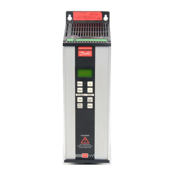
Page 46
The push buttons There are eight keys on the frequency converter’s control panel. The different keys and their functions are described overleaf. Stop – Menu Data Reset Fwd. Start Rev. MG.20.B6.02 – VLT is a registered Danfoss trademark… -
Page 47
It is not possible to delete or alter the values of PARAMETER GROUP the factory setting. DATA GROUP To alter some values, you will have to stop the motor first by pressing the “Stop/Reset” key. MG.20.B6.02 – VLT is a registered Danfoss trademark… -
Page 48
Parameter group by using the “Menu” key. between the menus by means of the “+” and “−” keys. 00,0 Hz Parameter number flashes 0.. OPERATION Menu group 0.. = Cursor flashes SETTING Name MG.20.B6.02 – VLT is a registered Danfoss trademark… -
Page 49
VLT. If TRIP LOCKED is displayed you must switch off the VLT and then switch it on again, and then press the “Stop/Reset” key. ALARM Reset mode TRIP Reason for alarm OVERVOLTAGE MG.20.B6.02 – VLT is a registered Danfoss trademark… -
Page 50
® 2000 Series MG.20.B6.02 – VLT is a registered Danfoss trademark… -
Page 51
Operation and display (group 0) ….Page 52 Load and motor (group 1) ……Page 52 Serial data interface (group 5) ….Page 54 VLT status ……….Page 56 VLT control commands ……Page 57 MG.20.B6.02 – VLT is a registered Danfoss trademark… -
Page 52
Manual tuning is possible in parameters 107-112 for adjustment of values. Control with open loop MG.20.B6.02 – VLT is a registered Danfoss trademark… -
Page 53
At stop the output (integrator) is set to 0 so that a restart follows the normal start situation. Control with closed loop MG.20.B6.02 – VLT is a registered Danfoss trademark… -
Page 54
Serial data interface (group 5..) Protocol: Using the serial RS 232 port (terminals 71 and 72) you The communication protocol for the VLT 2000 Series can read and set parameters of the VLT frequency consists of 22 ASCII characters. These characters converter and issue reference and control commands. -
Page 55
Used for summary control. If no control is necessary cancel the function using ? (ASCII: 63) in the two by- tes. Byte 22 Stop byte stating the end of the telegram. The character > is used (ASCII: 62) MG.20.B6.02 – VLT is a registered Danfoss trademark… -
Page 56
Byte 7 Byte 6 Byte 5 · ASCII 1/2 byte 1/2 byte 1/2 byte 1/2 byte Note: Each byte consists of 8 bits, but the frequency converter uses only the last 4 bits. MG.20.B6.02 – VLT is a registered Danfoss trademark… -
Page 57
Byte 7 Byte 6 Byte 5 ASCII 1/2 byte 1/2 byte 1/2 byte 1/2 byte Note: Each byte consists of 8 bits, but the frequency converter uses only the last 4 bits. MG.20.B6.02 – VLT is a registered Danfoss trademark… -
Page 59
® 2000 Series Chapter 6 Description of parameters ……Page 61 MG.20.B6.02 – VLT is a registered Danfoss trademark… -
Page 61
This function is selected for access to local reference even when the unit is operated remotely. = Factory setting. Text in ( ) = Display text. The figures in [ ] are used in bus communication. MG.20.B6.02 – VLT is a registered Danfoss trademark… -
Page 62
If data change is attempted with data change lock, the display shows: DATA LOCKED. = Factory setting. Text in ( ) = Display text. The figures in [ ] are used in bus communication. MG.20.B6.02 – VLT is a registered Danfoss trademark… -
Page 63
Parameters 107, 108, 109, 110 and 111 are changed automatically when the value of parameter 104 is changed. = Factory setting. Text in ( ) = Display text. The figures in [ ] are used in bus communication. MG.20.B6.02 – VLT is a registered Danfoss trademark… -
Page 64
(RMS). The magnetising current is then set to the measured value. = Factory setting. Text in ( ) = Display text. The figures in [ ] are used in bus communication. MG.20.B6.02 – VLT is a registered Danfoss trademark… -
Page 65
Therefore it is lower than the value calculated. The compensation will give the necessary voltage supplement. = Factory setting. Text in ( ) = Display text. The figures in [ ] are used in bus communication. MG.20.B6.02 – VLT is a registered Danfoss trademark… -
Page 66
114 is not of a suitable level. If you choose 100% the feedback signal is not changed. = Factory setting. Text in ( ) = Display text. The figures in [ ] are used in bus communication. MG.20.B6.02 – VLT is a registered Danfoss trademark… -
Page 67
(para. 201) but the highest output frequency is limited by f (para. 202) = Factory setting. Text in ( ) = Display text. The figures in [ ] are used in bus communication. MG.20.B6.02 – VLT is a registered Danfoss trademark… -
Page 68
If the switching frequency is higher than 4.5 kHz this period will be shorter. = Factory setting. Text in ( ) = Display text. The figures in [ ] are used in bus communication. MG.20.B6.02 – VLT is a registered Danfoss trademark… -
Page 69
VLT unit with a brake function and installation of a brake resistor. = Factory setting. Text in ( ) = Display text. The figures in [ ] are used in bus communication. MG.20.B6.02 – VLT is a registered Danfoss trademark… -
Page 70
27 if a DC braking time and a DC brake voltage have been recorded. = Factory setting. Text in ( ) = Display text. The figures in [ ] are used in bus communication. MG.20.B6.02 – VLT is a registered Danfoss trademark… -
Page 71
AUTO START. Warning: The motor may start without warning, if Auto reset selected. = Factory setting. Text in ( ) = Display text. The figures in [ ] are used in bus communication. MG.20.B6.02 – VLT is a registered Danfoss trademark… -
Page 72
Digital reference 1 Digital reference 2 Digital reference 3 Digital reference 4 = Factory setting. Text in ( ) = Display text. The figures in [ ] are used in bus communication. MG.20.B6.02 – VLT is a registered Danfoss trademark… -
Page 73
215. (continued overleaf) = Factory setting. Text in ( ) = Display text. The figures in [ ] are used in bus communication. MG.20.B6.02 – VLT is a registered Danfoss trademark… -
Page 74
1 and 2. Digital reference 3 Digital reference 4 = Factory setting. Text in ( ) = Display text. The figures in [ ] are used in bus communication. MG.20.B6.02 – VLT is a registered Danfoss trademark… -
Page 75
RS 232/RS 485 adapter. Connection example where the signal is active high: = Factory setting. Text in ( ) = Display text. The figures in [ ] are used in bus communication. MG.20.B6.02 – VLT is a registered Danfoss trademark… -
Page 76
(parameter 201). = Factory setting. Text in ( ) = Display text. The figures in [ ] are used in bus communication. MG.20.B6.02 – VLT is a registered Danfoss trademark… -
Page 77
The PC/PLC may prompt for a value from an index between 0 and 19. = Factory setting. Text in ( ) = Display text. The figures in [ ] are used in bus communication. MG.20.B6.02 – VLT is a registered Danfoss trademark… -
Page 78
Unspecified inverter fault will usually occur with another alarm, e.g. Inverter overload. It will give the following reading: Unspecified inverter fault 256 + Inverter overload Reading in para. 502, index 18: MG.20.B6.02 – VLT is a registered Danfoss trademark… -
Page 79
Bus (BUS) Logical and (AND) Logical or (OR) Description: See parameter 510. = Factory setting. Text in ( ) = Display text. The figures in [ ] are used in bus communication. MG.20.B6.02 – VLT is a registered Danfoss trademark… -
Page 80
While the unit is storing data, the display will show (SAVE DATA) and flash in line C. = Factory setting. Text in ( ) = Display text. The figures in [ ] are used in bus communication. MG.20.B6.02 – VLT is a registered Danfoss trademark… -
Page 81
® 2000 Series Chapter 7 Status messages ……..Page 82 Alarm messages ……..Page 82 Warning messages ……..Page 83 Reset messages ……..Page 83 MG.20.B6.02 – VLT is a registered Danfoss trademark… -
Page 82
Check installation No, power off required, then reset OVER Load too heavy Yes, after VLT LOAD thermal protection is lower than 100% MOTOR Motor protection Yes, after VLT TRIP motor protection is zero MG.20.B6.02 – VLT is a registered Danfoss trademark… -
Page 83
VLT stops TRIP LOCKED Fault condition (over temp., short The power section No, power off circuit, ground fault) of the VLT of the VLT stops required, then reset MG.20.B6.02 – VLT is a registered Danfoss trademark… -
Page 85
Derating for air pressure ……Page 95 Derating for running at low speed ….Page 95 Derating for higher switching frequency than 4.5 kHz ……….Page 95 Cut-in current ……….Page 96 MG.20.B6.02 – VLT is a registered Danfoss trademark… -
Page 86
The plant, however, must comply with the basic EMC requirements of the directive. The installer can ensure this by using components, appliances and systems, which are CE-labelled according to the EMC directive. MG.20.B6.02 – VLT is a registered Danfoss trademark… -
Page 87
(control box), motor cable and motor plus any options stallation guidelines are applied. added. The Technical Construction File is prepared on this basis in cooperation with a duly authorised EMC laboratory (Competent Body). MG.20.B6.02 – VLT is a registered Danfoss trademark… -
Page 88
1 per 5 m of power cable (mains, motor and brake The cables must throughout their length be reinforced/double-isolated to other cables. MG.20.B6.02 – VLT is a registered Danfoss trademark… -
Page 89
Radio interference higher than 50 MHz (airborne) will filter reduces the leak current I (see figure below). particularly affect the control electronics. VLT 2000 frequency converters with built-in RFI filter and without motor coils fulfil the EMC emission requirements. MG.20.B6.02 – VLT is a registered Danfoss trademark… -
Page 90
According to experience, most installations represent only a slight risk of any interference from radiation. MG.20.B6.02 – VLT is a registered Danfoss trademark… -
Page 91
AD: Air Discharge Differential mode CD: Contact Discharge Common mode Injection on cable shield CCC: Capacitive clamp coupling ** 2,3 x Û : max. testpulse 1250 V DCN: Direct coupling network PEAK MG.20.B6.02 – VLT is a registered Danfoss trademark… -
Page 92
The inverter turns off to protect the Short circuit transistors and the intermediate capactors, when a VLT 2000 Series is protected against short circuits. A certain voltage level is reached. short circuit between two output phases will cause overcurrent in the inverter. However, each switch of… -
Page 93
The variable switching frequency affects the losses running directly on the mains. in the VLT 2000 Series. The efficiency will drop a little In general the internal switching frequency does not when the switching frequency is set to a value higher affect the efficiency of small motors. -
Page 94
At higher temperatures, derating will not be possible due to the load-independent temperature on the SMPS transistors. The derating for VLT 2010-2060 40 °C: 100% output, 45 °C: 84% output, 50 °C: 67% output, 55 °C: 50% output MG.20.B6.02 – VLT is a registered Danfoss trademark… -
Page 95
60% at 16 kHz (see dia- motor coils of the frequency converter. gram). The maximum permitted motor cable length is 40 m of screened cable. Derating for higher switching frequency 100% [kHz] MG.20.B6.02 – VLT is a registered Danfoss trademark… -
Page 96
28.8 A 0.11 A² s VLT 2030 94.4 A 14.4 A² s VLT 2040 94.4 A 14.4 A² s VLT 2050 136 A 25.4 A² s VLT 2060 136 A 25.4 A² s MG.20.B6.02 – VLT is a registered Danfoss trademark… -
Page 97
® 2000 Series Chapter 9 Troubleshooting ……… Page 98 Your parameter settings ……Page 102 Factory settings ……..Page 105 MG.20.B6.02 – VLT is a registered Danfoss trademark… -
Page 98
Troubleshooting Service The fault location procedure is described on the Danfoss wil repair the new VLT 2000 1/3 phase, 230 following pages. V and the VLT 2000 3-phase 380-460 V. The service A total of 5 symptoms are described in the flow policy is based on replacement of vital parts. -
Page 99
Does the fault disappear? Ensure that the foregoing step is ok: The fault can be caused by short-circuiting on the Call Danfoss control signals. The 24 V for assistance supply might be short- circuited. MG.20.B6.02 – VLT is a registered Danfoss trademark… -
Page 100
003 = Local parameter 004 =Change by means of “+” and “-”. Does the motor run? Contact Danfoss. Check whether the control signals to the control card are ok. MG.20.B6.02 – VLT is a registered Danfoss trademark… -
Page 101
® 2000 Series Symptom VLT frequency converter trips out, OVERVOLTAGE displayed and motor does not run. Is the brake resistor and the connection to it OK? Replace the brake print. MG.20.B6.02 – VLT is a registered Danfoss trademark… -
Page 102
013 DATA CHG. LOCK X NOT LOCKED LOCKED 101 SPEED CONTROL OPEN LOOP SLIP COMP. CLOSED LOOP 102 CURRENT LIMIT PROGRAM SET 10 VDC SIGNAL 20 mA SIGNAL X = factory settings MG.20.B6.02 – VLT is a registered Danfoss trademark… -
Page 103
AUTORESET 5 310 TRIP DLY@C.LIM SECONDS 315 MOTOR THERMALX PROTECT-OFF ONLY WARNING TRIP 402 INPUT 18 START LATCH START NO OPERATION SPEED UP SPEED SELECT REVERSING RESET&START COAST/START X = factory settings MG.20.B6.02 – VLT is a registered Danfoss trademark… -
Page 104
505 D.C. BRAKE DIGITAL LOGICAL AND LOGICAL OR 506 START DIGITAL LOGICAL AND LOGICAL OR 507 DIRECTION DIGITAL LOGICAL AND LOGICAL OR 508 RESET DIGITAL LOGICAL AND LOGICAL OR X = factory settings MG.20.B6.02 – VLT is a registered Danfoss trademark… -
Page 105
121 PROPRT/L GAIN 609 NO. OVERTEMPS 0.01 610 NO. OVERVOLTS 122 INTEGRAL TIME 125 FEEDBACK SCALE 100% ) Can be changed in both setups ) Can be changed i Start mode (running motor) MG.20.B6.02 – VLT is a registered Danfoss trademark… -
Page 106
® 2000 Series MG.20.B6.02 – VLT is a registered Danfoss trademark… -
Page 107
® 2000 Series Chapter 10 Index …………Page 108 MG.20.B6.02 – VLT is a registered Danfoss trademark… -
Page 108
…………25 Protection against mains disturbance ….25 Factory-programmed optimization ….24 Push buttons …………. 46 Galvanic isolation ……….25 Quick Setup …………14 Grounding …………17 Groups (modes) ……….48 MG.20.B6.02 – VLT is a registered Danfoss trademark… -
Page 109
Survey of connection terminals ……42 Survey of terminals ……….16 Technical data ……….. 38 U/f ratio …………. 24 VLT control commands ……..57 VLT status …………56 VVC principle …………. 23 MG.20.B6.02 – VLT is a registered Danfoss trademark…
Каталоги
Инструкции
VLT MICRO DRIVE 051
VLT HVAC FC 102
VLT® AQUA Drive FC 202
VLT® HVAC Basic Drive FC 101
VLT HVAC Basic Drive
Размер файла: 3.83 мб
Привод VLT® HVAC Basic Drive
для автоматизации простых систем
управления вентиляторами
и насосами
Скачать
VLT® AutomationDrive FC 301/302
Инструкция FC 300
Размер файла: 9.75 мб
Инструкция по эксплуатации
VLT® AutomationDrive FC 300 VLT® Low Harmonic Drive
Скачать
Инструкция FC 300
Размер файла: 18.25 мб
Преобразователь VLT® AutomationDrive FC
300 для мощных приводов
Инструкция по эксплуатации
Скачать
Danfoss VLT 2800
Danfoss VLT 2900
Danfoss VLT 5000
Danfoss VLT 2000
Danfoss VLT 6000
Danfoss Vedadrive

The Quick Setup shown is based on the assumption
that you want your VLT to operate with the following
setup:
1. External start/stop
2. Potentiometer connected for external speed control
3. Option to change rotation direction
4. Option to select a fixed speed (Jog)
Standard motor with constant torque load without brake module on the frequency converter
Step
Parameter
Designation
1
000
Language
2
103
Motor power
3
104
Motor voltage
4
105
Motor frequency
5
201
Min. frequency
6
202
Max. frequency
7
215
Ramp up 1
8
216
Ramp down 1
9
Start
the frequency
converter
If a brake module is mounted, make the following settings
Step
Parameter
Designation
1
300
Brake function
2
Start
the frequency
converter
If you want local operation and start, make the following settings
Step
Parameter
Designation
1
003
Operation site
2
004
Local reference
MG.20.B6.02 – VLT is a registered Danfoss trademark
VLT
®
2000 Series
If you use a brake module, you must program
one parameter more, and two more if you
want local operation via the display keys.
This will appear from the two tables at the bottom.
To store the data press the «menu» key!
When you have connected your VLT, as described on
the previous page, you must program a few parame-
eters.
Perform steps 1-9 for Quick Setup.
Settings
Choose English
Read motor plate
Read motor plate
Read motor plate
Set wanted frequency
Set wanted frequency
Set wanted ramping time
Set wanted ramping time
This is done by supplying terminals 18 and 27
with 24 V DC from the frequency converter’s terminal 12
or by using an external 24 V DC voltage
Settings
If a brake module is used, choose Applied
This is done by supplying terminals 18 and 27
with 24 V DC from the frequency converter’s terminal 12,
or by using an external 24 V DC voltage
Settings
Choose Local
Record wanted output frequency by means
of the «+» and «−» keys
Display indication
ENGLISH
Display indication
APPLIED
Display indication
LOCAL
15
Преобразователь частоты Danfoss серии VLT Micro Drivo FC 51
Преобразователь частоты Danfoss серии VLT Midi Drive FC 280
Преобразователь частоты Danfoss серии VLT AQUA High Power
Преобразователь частоты Danfoss серии VLT AQUA Low Harmonic Drive
Преобразователь частоты Danfoss серии VLT AQUA Drive FC 202
Преобразователь частоты Danfoss серии VLT AutomationDrive FC 360
Преобразователь частоты Danfoss серии VLT Refrigeration Drive FC 103 110-250 kW
Преобразователь частоты Danfoss серии VLT HVAC Basic Drive FC 101
Преобразователь частоты Danfoss серии VLT HVAC Drive FC102 1,1-90 кВт
Преобразователь частоты Danfoss серии VLT HVAC Drive FC102 315-1400 kW
Преобразователь частоты Danfoss серии VLT HVAC FC100 110-400 кВт
Преобразователь частоты Danfoss серии VLT AutomationDrive FC 301/302 0,25-75 кВт
Преобразователь частоты Danfoss серии VLT AutomationDrive FC 300 более 90 кВт
Преобразователь частоты Danfoss серии VLT Automation Low Harmonic Drive
Преобразователь частоты Danfoss серии VLT AutomationDrive FC 302 12-импульсный
Преобразователь частоты Danfoss серии VLT AutomationDrive FC 300 90-1200 кW
Преобразователь частоты Danfoss серии VLT AutomationDrive FC 300 90-315 кВт
Преобразователь частоты Danfoss серии VLT AQUA Drive FC 202 315-1400 kW
Преобразователь частоты Danfoss серии VLT Decentral Drive FCD 302
Преобразователь частоты Danfoss серии VLT DriveMotor FCP 106/FCM 106
Преобразователь частоты Danfoss серии VACON NX
Преобразователь частоты Danfoss серии VACON NX
Преобразователь частоты Danfoss серии VACON 100 FLOW
Преобразователь частоты Danfoss серии VACON 100 FLOW
Преобразователь частоты Danfoss серии VACON 100-IP00
Преобразователь частоты Danfoss серии VACON 100-закрытого типа
Преобразователь частоты Danfoss серии VACON 100 FLOW
Преобразователь частоты Danfoss серии VACON 100 FLOW
Преобразователь частоты Danfoss серии VACON 100
Преобразователь частоты Danfoss серии VACON 100
Преобразователь частоты Danfoss серии VACON 20X_100X
Преобразователь частоты Danfoss серии VACON 20
Преобразователь частоты Danfoss серии VACON 20
Преобразователь частоты Danfoss серии VACON 20
Преобразователь частоты Danfoss серии VLT Soft Starter MCD 600
Преобразователь частоты Danfoss серии VLT Soft Starter MCD 500
Преобразователь частоты Danfoss серии VLT Compakt Starter MCD 201
Преобразователь частоты Danfoss серии VLT Compakt Starter MCD 202
Преобразователь частоты Danfoss серии VLT Refrigeration Drive FC 103 1,1-90 кВт
Преобразователь частоты Danfoss серии VACON NX
Если у Вас появились вопросы по настройке, эксплуатации и ремонту оборудования или не нашлась нужная документация, свяжитесь с техническими специалистами нашей компании.
Преобразователи частоты ABB
Серия
Скачать PDF
![]()
![]()
—
![]()
![]()
![]()
![]()
![]()
![]()
![]()
—
![]()
![]()
![]()
![]()
![]()
![]()
![]()
![]()
![]()
—
![]()
![]()
—
![]()
![]()
—
![]()
![]()
![]()
![]()
![]()
![]()
![]()
![]()
—
![]()
—
![]()
—
![]()
—
![]()
—
Преобразователи частоты Advanced Control
Серия
Скачать PDF
![]()
![]()
![]()
—
![]()
![]()
![]()
—
![]()
![]()
![]()
![]()
![]()
—
![]()
![]()
—
![]()
—
![]()
![]()
![]()
![]()
![]()
—
![]()
![]()
![]()
![]()
![]()
![]()
![]()
![]()
![]()
![]()
![]()
—
![]()
![]()
![]()
![]()
—
![]()
![]()
![]()
—
![]()
![]()
![]()
![]()
![]()
![]()
![]()
![]()
Преобразователи частоты B&R Automation
Серия
Скачать PDF
![]()
—
—
![]()
Преобразователи частоты Bosch Rexroth
Серия
Скачать PDF
![]()
—
![]()
—
![]()
—
![]()
—
![]()
—
Преобразователи частоты Danfoss
Серия
Скачать PDF
![]()
—
![]()
![]()
—
![]()
![]()
—
![]()
—
![]()
—
![]()
—
![]()
—
—
![]()
![]()
![]()
![]()
—
Преобразователи частоты Delta Electronics
Серия
Скачать PDF
![]()
—
![]()
—
![]()
![]()
![]()
—
![]()
—
![]()
—
![]()
![]()
![]()
—
![]()
—
![]()
![]()
Преобразователи частоты EasyDrive
Серия
Скачать PDF
![]()
—
![]()
—
Преобразователи частоты Eaton
Серия
Скачать PDF
![]()
![]()
—
![]()
![]()
![]()
Преобразователи частоты Emotron
Серия
Скачать PDF
—
![]()
![]()
—
![]()
—
—
![]()
—
![]()
![]()
—
![]()
—
![]()
—
—
![]()
![]()
![]()
Преобразователи частоты Erman
Серия
Скачать PDF
![]()
—
![]()
—
![]()
—
![]()
—
![]()
—
![]()
—
![]()
—
![]()
—
![]()
—
Преобразователи частоты ESQ
Серия
Скачать PDF
![]()
—
![]()
—
![]()
—
![]()
—
![]()
—
![]()
—
![]()
—
![]()
—
![]()
—
![]()
—
![]()
—
Преобразователи частоты Eura Drives
Серия
Скачать PDF
![]()
—
![]()
—
![]()
—
Преобразователи частоты Fuji Electric
Серия
Скачать PDF
![]()
![]()
—
![]()
—
![]()
![]()
![]()
![]()
![]()
![]()
![]()
![]()
—
![]()
![]()
![]()
![]()
![]()
![]()
—
![]()
—
![]()
![]()
![]()
![]()
![]()
![]()
![]()
—
![]()
—
![]()
![]()
![]()
![]()
—
![]()
—
—
![]()
![]()
![]()
Преобразователи частоты Gefran
Серия
Скачать PDF
—
![]()
—
![]()
—
![]()
—
![]()
—
![]()
—
![]()
—
![]()
—
![]()
—
![]()
—
![]()
—
![]()
—
![]()
Преобразователи частоты Grandrive
Серия
Скачать PDF
![]()
—
Преобразователи частоты Hitachi
Серия
Скачать PDF
—
![]()
![]()
—
![]()
![]()
![]()
![]()
![]()
![]()
![]()
![]()
![]()
![]()
![]()
—
—
![]()
Преобразователи частоты Hyundai
Серия
Скачать PDF
![]()
—
![]()
—
![]()
—
![]()
—
![]()
—
Преобразователи частоты IDS Drive
Серия
Скачать PDF
![]()
—
![]()
—
![]()
—
![]()
—
![]()
—
![]()
—
![]()
—
Преобразователи частоты Innovert
Серия
Скачать PDF
![]()
—
![]()
—
![]()
—
![]()
—
![]()
—
![]()
—
![]()
—
![]()
—
![]()
—
![]()
—
Преобразователи частоты Instart
Серия
Скачать PDF
![]()
—
![]()
—
![]()
—
![]()
—
Преобразователи частоты Invertek Drives
Серия
Скачать PDF
![]()
—
![]()
—
![]()
—
![]()
![]()
—
![]()
—
![]()
![]()
—
—
![]()
![]()
—
—
![]()
—
![]()
—
![]()
Преобразователи частоты INVT
Серия
Скачать PDF
![]()
—
![]()
![]()
—
![]()
![]()
—
![]()
—
![]()
—
![]()
—
—
![]()
![]()
—
![]()
![]()
![]()
—
![]()
![]()
![]()
—
![]()
—
![]()
—
![]()
—
![]()
![]()
![]()
—
—
![]()
![]()
—
Преобразователи частоты Lenze
Серия
Скачать PDF
![]()
—
![]()
—
![]()
—
![]()
![]()
—
![]()
![]()
—
![]()
—
—
![]()
Преобразователи частоты LS
Серия
Скачать PDF
![]()
—
![]()
—
![]()
—
![]()
—
![]()
—
—
![]()
![]()
—
![]()
—
![]()
—
—
![]()
![]()
—
—
![]()
![]()
—
![]()
—
—
![]()
![]()
—
—
![]()
![]()
—
—
![]()
Преобразователи частоты Mitsubishi Electric
Серия
Скачать PDF
![]()
![]()
![]()
![]()
![]()
![]()
![]()
![]()
![]()
![]()
![]()
![]()
![]()
![]()
![]()
![]()
![]()
![]()
![]()
![]()
![]()
![]()
![]()
![]()
![]()
![]()
Преобразователи частоты NORD
Серия
Скачать PDF
![]()
—
![]()
![]()
![]()
—
—
![]()
Преобразователи частоты Omron
Серия
Скачать PDF
![]()
![]()
![]()
![]()
—
![]()
![]()
![]()
![]()
![]()
![]()
![]()
—
![]()
![]()
![]()
![]()
—
![]()
—
![]()
![]()
![]()
![]()
![]()
![]()
![]()
![]()
![]()
![]()
![]()
![]()
![]()
![]()
![]()
![]()
![]()
![]()
Преобразователи частоты ONI
Серия
Скачать PDF
![]()
—
![]()
—
![]()
—
Преобразователи частоты OptimusDrive
Серия
Скачать PDF
![]()
—
![]()
![]()
![]()
—
—
![]()
—
![]()
![]()
—
Преобразователи частоты Profimaster
Серия
Скачать PDF
![]()
—
![]()
—
Преобразователи частоты Prostar
Серия
Скачать PDF
![]()
—
![]()
—
![]()
—
Преобразователи частоты Schneider Electric
Серия
Скачать PDF
![]()
![]()
![]()
![]()
![]()
![]()
![]()
![]()
![]()
![]()
![]()
![]()
![]()
![]()
![]()
![]()
![]()
![]()
—
![]()
![]()
![]()
![]()
![]()
![]()
—
![]()
![]()
![]()
![]()
![]()
![]()
![]()
![]()
—
![]()
![]()
![]()
![]()
![]()
![]()
—
![]()
—
—
![]()
![]()
—
![]()
—
Преобразователи частоты Sew-Eurodrive
Серия
Скачать PDF
![]()
![]()
![]()
—
Преобразователи частоты Siemens
Серия
Скачать PDF
![]()
![]()
![]()
—
![]()
![]()
![]()
—
![]()
![]()
![]()
—
![]()
![]()
![]()
![]()
![]()
![]()
![]()
![]()
![]()
![]()
—
![]()
![]()
—
—
![]()
![]()
—
—
![]()
![]()
![]()
![]()
![]()
![]()
![]()
![]()
![]()
![]()
—
—
![]()
![]()
![]()
Преобразователи частоты TECORP
Серия
Скачать PDF
![]()
—
![]()
—
![]()
—
![]()
—
![]()
—
—
![]()
—
![]()
![]()
—
Преобразователи частоты Toshiba
Серия
Скачать PDF
![]()
—
![]()
—
![]()
—
![]()
![]()
![]()
—
![]()
—
![]()
—
Преобразователи частоты Vacon
Серия
Скачать PDF
![]()
![]()
![]()
![]()
![]()
![]()
![]()
![]()
![]()
![]()
![]()
![]()
![]()
![]()
![]()
![]()
![]()
![]()
![]()
![]()
![]()
![]()
![]()
![]()
—
![]()
—
![]()
![]()
![]()
—
![]()
![]()
![]()
![]()
![]()
![]()
![]()
—
![]()
![]()
![]()
—
![]()
![]()
![]()
![]()
![]()
—
![]()
![]()
![]()
—
![]()
![]()
![]()
![]()
![]()
Преобразователи частоты Yaskawa
Серия
Скачать PDF
![]()
![]()
![]()
![]()
—
![]()
![]()
![]()
—
![]()
—
![]()
—
![]()
—
![]()
![]()
—
Преобразователи частоты Веспер
Серия
Скачать PDF
![]()
—
![]()
—
![]()
—
![]()
—
![]()
—
![]()
—
![]()
—
![]()
—
![]()
—
![]()
—
![]()
—
![]()
—
![]()
—
![]()
—
![]()
—
![]()
—
Преобразователи частоты Лидер
Серия
Скачать PDF
![]()
—
![]()
—
![]()
—
![]()
—
![]()
—
Преобразователи частоты Овен
Серия
Скачать PDF
![]()
—
![]()
—
![]()
—
Преобразователи частоты ОптимЭлектро
Серия
Скачать PDF
![]()
—
![]()
—
Преобразователи частоты Русэлком
Серия
Скачать PDF
![]()
—
![]()
—
![]()
—
![]()
—
![]()
—
![]()
—
![]()
—
![]()
—
![]()
—
Преобразователи частоты Триол
Серия
Скачать PDF
![]()
—
![]()
—
![]()
—
![]()
—
Преобразователи частоты Электротекс-ИН
Серия
Скачать PDF
![]()
—
Устройства плавного пуска ABB
Серия
Скачать PDF
![]()
![]()
Устройства плавного пуска Advanced Control
Серия
Скачать PDF
![]()
—
![]()
![]()
![]()
![]()
![]()
![]()
![]()
![]()
![]()
![]()
![]()
![]()
![]()
![]()
![]()
—
![]()
![]()
![]()
![]()
![]()
—
Устройства плавного пуска AuCom Electronics
Серия
Скачать PDF
![]()
—
Устройства плавного пуска Danfoss
Серия
Скачать PDF
—
![]()
—
![]()
—
![]()
—
![]()
Устройства плавного пуска Eura Drives
Серия
Скачать PDF
![]()
—
Устройства плавного пуска Schneider Electric
Серия
Скачать PDF
![]()
![]()
—
![]()
![]()
![]()
![]()
![]()
![]()
![]()
Источники питания Delta Electronics
Серия
Скачать PDF
![]()
![]()
Сервосистемы Delta Electronics
Серия
Скачать PDF
![]()
![]()
![]()
![]()
![]()
![]()
![]()
![]()
—
![]()
![]()
—
![]()
—
Сервосистемы Fuji Electric
Серия
Скачать PDF
—
![]()
Энкодеры Delta Electronics
Серия
Скачать PDF
![]()
—
Модульная автоматика Fuji Electric
Серия
Скачать PDF
![]()
—
![]()
—
![]()
—
![]()
—
![]()
—
![]()
—
![]()
—
![]()
—
![]()
—
![]()
—
![]()
—
Модульная автоматика LS
Серия
Скачать PDF
![]()
—
![]()
—
![]()
—
![]()
—
![]()
—
![]()
—
![]()
—
![]()
—
![]()
—
![]()
—
![]()
—
![]()
—
![]()
—
![]()
—
![]()
—
![]()
—
![]()
—
![]()
—
![]()
—
![]()
—
![]()
—
![]()
—
—
![]()
![]()
—