De Dietrich
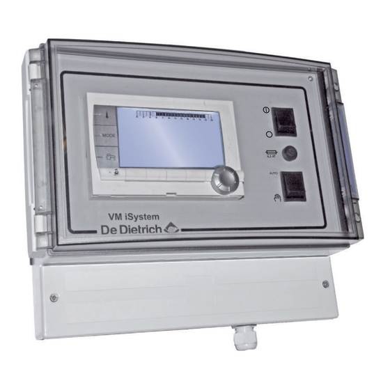
Настенный модуль с электронной системой регулирования DIEMATIC VM iSystem позволяет управлять и регулировать 2 дополнительных контура.
Возможно подключить между собой до 20 модулей DIEMATIC VM и осуществить различные комбинации в зависимости от типа установки:
• в сочетании c системой регулирования котла для управления дополнительными контурами.
• установка с котлом без системы регулирования (например, со стандартной панелью управления или панелью управления B3).
Скачать
Pdf 4.49 Mb
Язык: RU
- Manuals
- Brands
- DeDietrich Manuals
- Controller
- VM iSystem
- Installation and service manual
-
Bookmarks
Quick Links
FR — DE — EN — NL — IT — ES — PL — RU
Régulation
VM iSystem — AD281
300027106-001-02 (0450281003)
C003674-B
Notice
d’installation et
d’entretien
Notice d’installation
rapide
FR
Related Manuals for DeDietrich VM iSystem
Summary of Contents for DeDietrich VM iSystem
-
Page 1
FR — DE — EN — NL — IT — ES — PL — RU Régulation VM iSystem — AD281 Notice d’installation et d’entretien C003674-B Notice d’installation rapide 300027106-001-02 (0450281003) -
Page 2
La présence de ce logo sur le produit signifie la conformité de l’équipe ment avec les Directives de l’Union Européenne. The presence of this symbol on the product signifies that the equipment conforms with EU directives. Dieses Symbol am Produkt bedeutet, dass das Gerät den EU-Richtlinien entspricht De aanwezigheid van dit symbool op het product betekent dat de uitrus… -
Page 3
La présence de ce logo sur le produit indique qu’il ne doit pas être jeté avec les déchets ménagers mais orienté vers une structure de récupéra tion et de recyclage appropriée. The presence of this symbol on the product indicates that it must not be disposed of with household waste, but instead sent to appropriate recov… -
Page 4
1. Description VM iSystem — AD281 Description Généralités La notice d’installation rapide est destinée au professionnel pour une installation et mise en service standard. ¼ Pour toute autre type d’installation ou pour plus d’informations, se référer à la notice d’installation et d’entretien et à la notice d’utilisation. -
Page 5
VM iSystem — AD281 2. Installation Installation Montage Le module VM iSystem peut être fixé au mur ou dans une armoire électrique. 1. Percer 3 trous. (1) Gabarit de perçage 2. Accrocher le module. 3. Ouvrir le capot de protection. -
Page 6
2. Installation VM iSystem — AD281 4 Italie : Les raccordements électriques doivent être conformes à la norme CEI. 4 Les indications des schémas électriques livrés avec la chaudière. 4 Les recommandations de la présente notice. ATTENTION Séparer les câbles de sondes des câbles 230 V. -
Page 7
VM iSystem — AD281 2. Installation Raccordement du BUS cascade S.SYST Sonde système — Colis AD250 Câble BUS — Colis AD124 / AD134 / DB119 Commande à distance (Circuit C) — Colis AD254 / AD285 Sonde ECS — Colis AD212… -
Page 8
La sonde extérieure qui équipe le tableau de commande de la chaudière sert de référence à l’ensemble des VM iSystem . Chaque circuit de chaque régulation VM iSystem peut être équipé d’une sonde extérieure (régulation de zone). -
Page 9
VM iSystem — AD281 2. Installation 2.2.5. Raccordement de deux circuits chauffage et d’un ballon eau chaude sanitaire 0V + CDI C CDI B/ 0-10V/ ALIM S.SYST E.TEL 230V/50Hz C003685-D A Vanne 3 voies circuit B I Sonde ECS (Colis AD212) Ne pas utiliser le connecteur de simulation livré… -
Page 10
à partir de 20 et sans omettre de numéro. Ne jamais attribuer C002286-C le même codage à 2 régulations VM iSystem différentes. Fonctionnement avec les régulations Diematic-m 3 — Diematic V3V+ iSystem — Priorité… -
Page 11
¼ Pour les réglages utilisateur, se référer à la notice d’utilisation. Défauts En cas de défaut de fonctionnement, le module VM iSystem clignote et affiche un message d’erreur et un code correspondant. 1. Noter le code affiché. Le code est important pour le dépistage correct et rapide du type de dérangement et pour une éventuelle assistance technique. -
Page 12
3. Mise en service VM iSystem — AD281 11/10/2017 — 300027106-001-02 (0450281003) -
Page 13
Regelung VM iSystem — AD281 Installations- und Wartungsanleitung C003674-B Schnellinstallations- Anleitung 300027106-001-01 (0450281003) -
Page 14
1. Beschreibung VM iSystem — AD281 Beschreibung Allgemeine Angaben Die Schnellinstallationsanleitung ist für den Fachhandwerker für eine Standard-Installation und -Inbetriebnahme bestimmt. ¼ Für jeden anderen Anlagentyp bzw. weitere Informationen siehe die Installations- und Wartungsanleitung und die Bedienungsanleitung. WARNUNG Die Installation und die Inbetriebnahme darf nur durch einen qualifizierten Fachbetrieb erfolgen. -
Page 15
VM iSystem — AD281 2. Anlage Anlage Montage Das VM iSystem-Modul kann an der Wand oder in einem Schaltschrank befestigt werden. 1. 3 Löcher bohren. (1) Bohrschablone 2. Das Modul befestigen. 3. Die Schutzabdeckung öffnen. 4. Die Einheit mit den 3 Schrauben befestigen. -
Page 16
2. Anlage VM iSystem — AD281 4 Italien: Die elektrischen Anschlüsse müssen der Norm CEI entsprechen. 4 Die Angaben der mit dem Heizkessel gelieferten Schaltpläne. 4 Die Empfehlungen dieser Anleitung. ACHTUNG Fühler- und 230V-führende Kabel müssen voneinander getrennt verlegt werden. -
Page 17
VM iSystem — AD281 2. Anlage Anschluss des BUS Kaskadenschaltung S.SYST Systemfühler — Kolli AD250 Kabel BUS — Kolli AD124 / AD134 / DB119 Fernbedienung (Kreis C) — Kolli AD254 / AD285 WWE-Fühler — Kolli AD212 CDI C O r BF CDI B / CDR Fernbedienung (Kreis B) — Kolli AD254 / AD285 Außenfühler — Kolli FM46… -
Page 18
Generators/en hängt vom vorliegenden Bedarf der Sekundärkreise ab. Der Außenfühler des Schaltfelds des Heizkessels dient als Referenz für alle VM iSystem . Der Kreis jeder VM iSystem -Regelung kann mit einem Außenfühler ausgestattet werden (Bereichsregelung). 11/10/2017 — 300027106-001-02 (0450281003) -
Page 19
VM iSystem — AD281 2. Anlage 2.2.5. Anschluss von zwei Heizungskreisen und einem Warmwasserspeicher 0V + CDI C CDI B/ 0-10V/ ALIM S.SYST E.TEL 230V/50Hz C003685-D A Dreiwegemischer Kreis B I WWE-Fühler (Kolli AD212) Der mit dem WWE-Fühler mitgelieferten Simulationsanschluss nicht benutzen. -
Page 20
3. Inbetriebnahme VM iSystem — AD281 Inbetriebnahme Erstmalige Einschaltung 1. Auf die gefederte Lasche drücken, um den Schutzdeckel zu öffnen. 2. Auf den Knopf ON drücken. 3. Auf den Knopf AUTO drücken. 4. Beim ersten Einschalten, wird das Menü SPRACHE angezeigt. Die gewünschte Sprache durch Drehen des Drehknopfs auswählen. -
Page 21
Installations- und Wartungsanleitung. ¼ Was die Benutzer-Einstellungen angeht, siehe die Bedienungsanleitung. Fehler Bei Betriebsstörungen blinkt das VM iSystem-Modul und eine Fehlermeldung mit Code wird angezeigt. 1. Notieren Sie den angezeigten Code. Der Code ist für die korrekte und schnelle Diagnose der Störungsart und für eine eventuelle technische Unterstützung wichtig. -
Page 22
3. Inbetriebnahme VM iSystem — AD281 11/10/2017 — 300027106-001-02 (0450281003) -
Page 23
Regulation VM iSystem — AD281 Installation and Service Manual C003674-B Quick installation guide 300027106-001-01 (0450281003) -
Page 24
1. Description VM iSystem — AD281 Description General The quick installation instructions are intended for professionals for standard installation and commissioning. ¼ For all other types of installation or for more information, refer to the installation and service manual and the user guide. -
Page 25
VM iSystem — AD281 2. Installation Installation Mounting The VM iSystem module can be affixed to the wall or in an electrical cabinet. 1. Drill 3 holes. (1) Drilling template 2. Affix the module. 3. Open the protective hood. 4. Secure the unit with the 3 screws. -
Page 26
2. Installation VM iSystem — AD281 4 The recommendations in the instructions. CAUTION Separate the sensor cables from the 230 V cables. Use 2 pipes or cable guides at least 10 cm apart. Keep to the polarity shown on the terminals: phase (L), neutral (N) and earth *. -
Page 27
VM iSystem — AD281 2. Installation ALIM 230V/50Hz C003567-C L C Heating pump circuit C 3 way valve circuit B D.H.W. load pump Safety contact — Factory fitted bridge 3 way valve circuit C Auxiliary pump L AUX L B Heating pump circuit B… -
Page 28
The outside temperature sensor fitted to the boiler’s control panel is used as the reference for each VM iSystem . Each circuit on each VM iSystem control system can be fitted with an outside temperature sensor (zone regulation). 11/10/2017 — 300027106-001-02… -
Page 29
VM iSystem — AD281 2. Installation 2.2.5. Connecting two circuits and a domestic hot water tank 0V + CDI C CDI B/ 0-10V/ ALIM S.SYST E.TEL 230V/50Hz C003685-D A 3 way valve circuit B I DHW sensor (Package AD212) Do not use the simulation connector delivered with the DHW sensor. -
Page 30
Assign a code (from 20 to 39) to the appliance. The codes assigned to the devices must always be done in increasing order starting with 20 and without omitting any numbers. Never assign the same code to 2 different VM iSystem control systems. C002286-C… -
Page 31
¼ For the user settings, refer to the user instructions. Faults If a malfunction occurs, the VM iSystem module flashes and displays an error message and a corresponding code. 1. Make a note of the code displayed. The code is important for the correct and rapid diagnosis of the type of failure and for any technical assistance that may be needed. -
Page 32
3. Commissioning VM iSystem — AD281 11/10/2017 — 300027106-001-02 (0450281003) -
Page 33
Regelaar VM iSystem — AD281 Installatie- en servicehandleiding C003674-B Snelle installatiehandleiding 300027106-001-01 (0450281003) -
Page 34
1. Beschrijving VM iSystem — AD281 Beschrijving Algemeen De snelle installatiehandleiding is bedoeld voor de vakman voor een standaard installatie en inbedrijfstelling. ¼ Zie voor alle andere soorten installatie of voor meer informatie de installatie- en onderhoudshandleiding en de gebruikshandleiding. -
Page 35
VM iSystem — AD281 2. Installatie Installatie Montage De module VM iSystem kan aan de muur of in een elektriciteitskast bevestigd worden. 1. Boor 3 gaten. (1) Boormal 2. Hang de module op. 3. Open de beschermkap. 4. Bevestig het geheel met de 3 schroeven. -
Page 36
2. Installatie VM iSystem — AD281 4 Italië: De elektrische aansluitingen dienen te beantwoorden aan de norm CEI. 4 De aanwijzingen van de met de ketel meegeleverde elektrische schema’s. 4 De aanbevelingen in de handleiding. OPGELET Scheid de sensorkabels van de 230V kabels. -
Page 37
VM iSystem — AD281 2. Installatie Aansluiting van de cascade BUS S.SYST Systeemsensor — Colli AD250 Kabel BUS — Colli AD124 / AD134 / DB119 Afstandsbediening (Kring C) — Colli AD254 / AD285 SWW-sensor — Colli AD212 CDI C O… -
Page 38
De buitenvoeler waarmee het bedieningspaneel van de verwarmingsketel is uitgerust, dient als referentie voor alle VM iSystem . Iedere kring van iedere regelaar VM iSystem kan uitgerust worden met een buitenvoeler (zoneregelaar). 11/10/2017 — 300027106-001-02 (0450281003) -
Page 39
VM iSystem — AD281 2. Installatie 2.2.5. Aansluiting van twee kringen en een SWW- boiler 0V + CDI C CDI B/ 0-10V/ ALIM S.SYST E.TEL 230V/50Hz C003685-D A Driewegklep kring B I SWW-sensor (Colli AD212) Niet de met de SWW-voeler meegeleverde simulatiestekker gebruiken. -
Page 40
Geef het apparaat een code (van 2 tot 10). De aan de apparaten toegewezen codes moeten altijd oplopen vanaf 2 en zonder een nummer over te slaan. Geef nooit dezelfde codering aan 2 verschillende regelaars VM iSystem. Bediening van een alles of niets generator 0/1+MGK ¼… -
Page 41
VM iSystem — AD281 3. Inbedrijfstelling 8. Plaats de 2 schroeven (meegeleverd in het zakje met documentatie) aan de voorzijde van de module om de beveiligingsindex IP21 te garanderen. Instellingen wijzigen De bedieningsautomaat van de ketel is ingesteld op de meest voorkomende cv-installaties. -
Page 42
3. Inbedrijfstelling VM iSystem — AD281 11/10/2017 — 300027106-001-02 (0450281003) -
Page 43
Regolazione VM iSystem — AD281 Istruzioni per l’installazione e la manutenzione C003674-B Istruzioni d’installazione rapida 300027106-001-01 (0450281003) -
Page 44
1. Descrizione VM iSystem — AD281 Descrizione Generalità Il manuale di installazione rapida è destinato al professionista per il montaggio e la messa in funzione standard. ¼ Per qualunque altro tipo di impianto o per maggiori informazioni, fare riferimento al manuale di installazione/manutenzione e al manuale di utilizzo. -
Page 45
VM iSystem — AD281 2. Installazione Installazione Montaggio Il modulo VM iSystem può essere fissato al muro o in un armadio elettrico. 1. Realizzare 3 fori. (1) Maschera di foratura 2. Agganciare il modulo. 3. Aprire il coperchio di protezione. -
Page 46
2. Installazione VM iSystem — AD281 4 Italia: I collegamenti elettrici devono essere conformi alla norma CEI. 4 Le indicazioni degli schemi elettrici in dotazione con la caldaia. 4 Le raccomandazioni contenute nelle istruzioni. ATTENZIONE Tenere i cavi delle sonde separati dai cavi 230 V. -
Page 47
VM iSystem — AD281 2. Installazione Collegamento del BUS cascata S.SYST Sonda sistema — Collo AD250 Cavo BUS — Collo AD124 / AD134 / DB119 Comando a distanza (Circuito C) — Collo AD254 / AD285 Sonda ACS — Collo AD212… -
Page 48
è legato alle effettive esigenze dei circuiti secondari. La sonda esterna presente sul quadro di comando della caldaia serve come riferimento per il gruppo di VM iSystem . Ogni circuito di ciascuna regolazione VM iSystem può essere provvisto di una sonda esterna (regolazione di zona). -
Page 49
VM iSystem — AD281 2. Installazione 2.2.5. Collegamento di due circuiti e di un bollitore acqua calda sanitaria 0V + CDI C CDI B/ 0-10V/ ALIM S.SYST E.TEL 230V/50Hz C003685-D A Valvola a 3 vie circuito B I Sonda ACS (Collo AD212) Non utilizzare il connettore di simulazione fornito con la sonde ECS. -
Page 50
3. Messa in servizio VM iSystem — AD281 Messa in servizio Prima messa in tensione 1. Premere la linguetta a molla per aprire il coperchio di protezione. 2. Premere il pulsante ON. 3. Premere il pulsante AUTO. 4. Alla prima alimentazione, il menù LINGUA è visualizzato. -
Page 51
¼ Per le impostazioni utente, fare riferimento al libretto di istruzioni. Difetti In caso di guasto di funzionamento, il modulo VM iSystem lampeggia e visualizza un messaggio d’errore ed un codice corrispondente. 1. Attenzione al codice visualizzato. -
Page 52
3. Messa in servizio VM iSystem — AD281 11/10/2017 — 300027106-001-02 (0450281003) -
Page 53
Regulación VM iSystem — AD281 Instrucciones de instalación y de mantenimiento C003674-B La guía de instalación rápida 300027106-001-01 (0450281003) -
Page 54
1. Descripción VM iSystem — AD281 Descripción Generalidades La guía de instalación rápida, dirigida al profesional, se emplea para efectuar una instalación y una puesta en servicio estándar. ¼ Para cualquier otro tipo de instalación o para obtener más información, consultar las instrucciones de instalación y mantenimiento y las instrucciones de uso. -
Page 55
VM iSystem — AD281 2. Instalación Instalación Montaje El módulo VM iSystem se puede fijar a la pared o dentro de un armario eléctrico de distribución. 1. Hacer 3 agujeros. (1) Plantilla de taladrado 2. Colgar el módulo. 3. Abrir la tapa de protección. -
Page 56
2. Instalación VM iSystem — AD281 4 Italia: Las conexiones eléctricas deben estar conformes con la norma CEI. 4 Las indicaciones de los esquemas eléctricos suministrados con la caldera. 4 Las recomendaciones de las instrucciones. ATENCION Separar los cables de sondas de los cables de 230 V. -
Page 57
VM iSystem — AD281 2. Instalación Conexión del BUS cascada S.SYST Sonda de sistema — Bulto AD250 Cable BUS — Bulto AD124 / AD134 / DB119 Mando a distancia (Circuito C) — Bulto AD254 / AD285 Sonda a.c.s. — Bulto AD212… -
Page 58
La sonda exterior correspondiente al cuadro de mando de la caldera sirve de referencia para el conjunto de las VM iSystem . Cada circuito de cada regulación VM iSystem puede incorporar una sonda exterior (regulación zonal). -
Page 59
VM iSystem — AD281 2. Instalación 2.2.5. Conexión de dos circuitos y un acumulador de agua caliente sanitaria 0V + CDI C CDI B/ 0-10V/ ALIM S.SYST E.TEL 230V/50Hz C003685-D A Válvula 3 vías circuito B I Sonda a.c.s. (Bulto AD212) No utilizar el conector de simulación suministrado con la sonda de ACS. -
Page 60
3. Puesta en marcha VM iSystem — AD281 Puesta en marcha Primera puesta en tensión 1. Apretar la lengüeta de muelle para abrir la cubierta de protección. 2. Pulsar el botón ON. 3. Pulsar el botón AUTO. 4. La primera vez que se enciende aparece el menú IDIOMA. -
Page 61
¼ Para conocer los ajustes del usuario, consultar el manual de uso. Defectos Si se produce un fallo de funcionamiento, el módulo VM iSystem parpadea y muestra un mensaje de error y el código correspondiente. 1. Anotar el código indicado. -
Page 62
3. Puesta en marcha VM iSystem — AD281 11/10/2017 — 300027106-001-02 (0450281003) -
Page 63
Regulator VM iSystem — AD281 Instrukcja instalowania i konserwacji C003674-B Instrukcja szybkiej instalacji 300027106-001-01 (0450281003) -
Page 64
1. Opis VM iSystem — AD281 Opis Informacje ogólne Instrukcje szybkiej instalacji są przeznaczone dla uprawnionych instalatorów dla standardowego instalowania i uruchomienia. ¼ Dla każdego innego typu instalacji lub dalszych informacji patrz Instrukcja instalowania i konserwacji oraz Instrukcja obsługi. OSTRZEŻENIE Instalacja i uruchomienie muszą… -
Page 65
VM iSystem — AD281 2. Instalacja Instalacja Montaż Moduł VM iSystem może być zamontowany na ścianie lub w szafce rozdzielczej. 1. Wywiercić 3 otwory. (1) Szablon otworów do wywiercenia 2. Zamocować moduł. 3. Zdjąć osłonę zabezpieczającą. 4. Przykręcić zespół 3 śrubami. -
Page 66
2. Instalacja VM iSystem — AD281 4 Włochy: Podłączenia elektryczne muszą być zgodne z normą CEI. 4 Danych zawartych na dostarczonych z kotłem schematach połączeń elektrycznych. 4 Zaleceń zawartych w tej instrukcji. UWAGA Kable czujników oraz pod napięciem 230V muszą być… -
Page 67
VM iSystem — AD281 2. Instalacja Podłączenie magistrali BUS w instalacji kaskadowej S.SYST Czujnik systemu — Pakiet AD250 Kabel BUS — Pakiet AD124 / AD134 / DB119 Zdalne sterowanie (Obieg C) — Pakiet AD254 / AD285 Czujnik c.w.u. — Pakiet AD212… -
Page 68
Konsola sterownicza kotła jest wiodąca dla BUS. Działanie generatora(-ów) zależy od zapotrzebowania obiegów wtórnych. Czujnik temperatury zewnętrznej konsoli służy jako odniesienie dla wszystkich regulatorów VM iSystem , nie posiadających własnego czujnika. Każdy regulator VM iSystem może być wyposażony we własny czujnik temperatury zewnętrznej (regulacja strefowa). -
Page 69
VM iSystem — AD281 2. Instalacja 2.2.5. Podłączenie dwóch obiegów i podgrzewacza c.w.u. 0V + CDI C CDI B/ 0-10V/ ALIM S.SYST E.TEL 230V/50Hz C003685-D A 3-drogowy zawór mieszający obiegu B I Czujnik c.w.u. (Pakiet AD212) Nie używać wtyku symulacji dostarczonego z czujnikiem c.w.u.. -
Page 70
Wybrać menu #SIEĆ. Wybrać parametr NUMER VM. Przydzielić kod (od 20 do 39) urządzeniu. Urządzeniom muszą być przypisane kody w kolejności rosnącej (rozpoczynając od 20). 2 regulatory VM iSystem nie mogą C002286-C posiadać tych samych kodów. Nie można pominąć żadnego kodu. -
Page 71
¼ Odnośnie nastaw wykonywanych przez użytkownika, patrz instrukcja obsługi. Usterki W razie wystąpienia zakłóceń w pracy, moduł VM iSystem miga, a na ekranie wyświetlany jest komunikat błędu i odpowiedni kod. 1. Zanotować wyświetlany kod. Kod odgrywa znaczną rolę przy korekcie i szybkiej diagnozie rodzaju usterki oraz dla ewentualnej pomocy technicznej. -
Page 72
3. Uruchomienie VM iSystem — AD281 11/10/2017 — 300027106-001-02 (0450281003) -
Page 73
Система регулирования VM iSystem — AD281 Инструкция по установке и техническому обслуживанию C003674-B Инструкция по быстрой установке 300027106-001-01 (0450281003) -
Page 74
1. Описание VM iSystem — AD281 Описание Общие сведения Краткая инструкция по установке предназначена для стандартного ввода в эксплуатацию квалифицированным специалистом. ¼ Для любого другого типа установки и для большей информации см. инструкцию по установке и техническому обслуживанию, а также инструкцию по эксплуатации. -
Page 75
VM iSystem — AD281 2. Установка Установка Монтаж Модуль VM iSystem может быть закреплен на стене или в электрическом шкафу. 1. Просверлить 3 отверстия. (1) Лекало для просверливания 2. Навесить модуль. 3. Открыть защитную крышку. 4. Закрепить систему при помощи 3 винтов. -
Page 76
2. Установка VM iSystem — AD281 4 Италия : Электрические подключения должны соответствовать стандарту CEI. 4 Обозначения электрических схем, поставляемых с котел. 4 Рекомендации инструкции. ВНИМАНИЕ Отделить кабели датчиков от кабелей 230 В. использовать 2 кабельных канала или кабелепровода, расположенных на расстоянии, как… -
Page 77
VM iSystem — AD281 2. Установка Подключение кабеля BUS каскада S.SYST Датчик системы — Ед. поставки AD250 Кабель BUS — Ед. поставки AD124 / AD134 / DB119 Дистанционное управление (контур C) — Ед. Датчик ГВС — Ед. поставки AD212 CDI C O r BF поставки… -
Page 78
BUS. Работа теплогенератора (теплогенераторов) связана с реальными потребностями в тепле вторичных контуров. датчик наружной температуры панели управления котла служит источником информации для всех VM iSystem . Каждый контур каждого модуля регулирования VM iSystem может быть оборудован датчиком наружной температуры (позонное регулирование). -
Page 79
VM iSystem — AD281 2. Установка 2.2.5. Подключение 2 контуров и водонагревателя горячей санитарно- технической воды CDI C CDI B/ 0V + 0-10V/ ALIM S.SYST E.TEL 230V/50Hz C003685-D A 3-ходовой клапан контура B I Датчик ГВС (Ед. поставки AD212) Не использовать разъём для симуляции из комплекта… -
Page 80
3. Ввод в эксплуатацию VM iSystem — AD281 Ввод в эксплуатацию Первое включение 1. Нажать на защёлку с пружиной, чтобы открыть защитную крышку. 2. Нажать на кнопку ON. 3. Нажать на кнопку AUTO. 4. Во время первого включения отображается меню ЯЗЫК. -
Page 81
назначаемые оборудованию, должны всегда идти в порядке возрастания, начиная с 20 и без пропуска номеров. Никогда не назначать одинаковый код 2 различным модулям регулирования VM iSystem. Работа с панелями управления Diematic-m 3 — Diematic 3Х.КЛ+ iSystem — Доступен приоритет ГВС. -
Page 82
3. Ввод в эксплуатацию VM iSystem — AD281 Неисправности В случае обнаружения неисправности во время работы на дисплее модуля мигает VM iSystem и отображается сообщение об ошибке и соответствующий код. 1. Записать отображаемый код. Код очень важен для быстрого и корректного выявления типа… -
Page 84
Зубарев переулок, д. 15/1 Бизнес-центр «Чайка Плаза», офис 309 +7 (495) 221-31-51 DUEDI S.r.l. DE DIETRICH THERMIQUE Iberia S.L.U. www.duediclima.it www.dedietrich-calefaccion.es Distributore Ufficiale Esclusivo Av. Princep d’Astúries 43-45 De Dietrich-Thermique Italia 08012 BARCELONA Via Passatore, 12 — 12010 +34 932 920 520…
This manual is also suitable for:
Ad281

EN
Regulation
VM iSystem – AD281
User Guide
C003674-B
300028026-001-03
Contents
1
Safety instructions .....................................................................................4
1.1
General safety instructions .................................4
1.2
Recommendations ................................................5
1.3
Liabilities ...............................................................6
1.3.1
1.3.2
1.3.3
2
3
About this manual ......................................................................................8
2.1
Symbols used .......................................................8
2.2
Abbreviations ........................................................8
Description ..................................................................................................9
3.1
Description of the keys ........................................9
3.2
Description of the display ..................................10
3.2.1
3.2.2
3.2.3
3.2.4
3.2.5
3.2.6
4
Key functions .........................................................10
Flame symbol ........................................................10
Solar (If connected) ...............................................10
Operating modes ...................................................11
Domestic Hot Water override ................................11
Other information ..................................................12
Operating the appliance ..........................................................................13
4.1
Browsing in the menus ......................................13
4.2
Reading out measured values ...........................14
4.3
Changing the settings ........................................15
4.3.1
4.3.2
4.3.3
4.3.4
4.3.5
4.3.6
4.3.7
4.3.8
1
Manufacturer’s liability .............................................6
Installer’s liability .....................................................6
User’s liability ..........................................................7
Setting the set point temperatures ........................15
Selecting the operating mode ...............................16
Forcing domestic hot water production .................17
Setting the contrast and lighting on the
display ...................................................................17
Setting the time and date ......................................18
Selecting a timer programme ................................18
Customising a timer programme ...........................19
Setting an annual clock .........................................21
28/10/2015 - 300028026-001-03
Contents
5
6
7
2
4.4
Installation shutdown .........................................23
4.5
Antifreeze protection ..........................................23
Troubleshooting .......................................................................................24
5.1
Messages (type code Mxx) ................................24
5.2
Faults ...................................................................24
Warranty ....................................................................................................27
6.1
General ................................................................27
6.2
Warranty terms ...................................................27
Appendix - Information on the Ecodesign and Energy Labelling
Directives ..................................................................................................28
28/10/2015 - 300028026-001-03
3
28/10/2015 - 300028026-001-03
VM iSystem – AD281
1. Safety instructions
1
Safety instructions
1.1
General safety instructions
DANGER
This appliance can be used by children aged
from 8 years and above and persons with
reduced physical, sensory or mental capabilities
or lack of experience and knowledge if they have
been given supervision or instruction concerning
use of the appliance in a safe way and
understand the hazards involved. Children shall
not play with the appliance. Cleaning and user
maintenance shall not be made by children
without supervision.
The user guide and the installation manual can
also be found on our internet site.
CAUTION
Allowance must be made for a means of
disconnection in the fixed pipes in accordance
with the regulations on installations.
CAUTION
If a power cord is provided with the appliance
and it turns out to be damaged, it must be
replaced by the manufacturer, its after sales
service or persons with similar qualifications in
order to obviate any danger.
CAUTION
Respect the maximum water inlet pressure to
ensure correct operation of the appliance,
referring to the chapter "Technical
Specifications".
CAUTION
Before any work, switch off the mains supply to
the appliance.
28/10/2015 - 300028026-001-03
4
VM iSystem – AD281
1. Safety instructions
CAUTION
Any operation on the installation must be
performed by a qualified technician respecting
professional regulations and in accordance with
this document.
CAUTION
Solar installations must be earthed to protect
them against lightning.
CAUTION
Operation of the thermostatic mixing valve on
the solar hot water tank outlet must be checked
on commissioning of the solar system.
CAUTION
Use only original spare parts.
CAUTION
Before any work, switch off the mains supply to
the appliance. Protect the installation against
any unwanted restarts.
1.2
Recommendations
CAUTION
Do not neglect to service the appliance. Service
the appliance regularly to ensure that it operates
correctly.
WARNING
Only qualified professionals are authorised to
work on the appliance and the installation.
WARNING
Heating water and domestic water must not
come into contact with each other. Domestic
water must not circulate via the exchanger.
4 To take advantage of the guarantee, no modifications
must be made to the appliance.
4 To reduce heat losses as much as possible, insulate
the pipes.
5
28/10/2015 - 300028026-001-03
1. Safety instructions
VM iSystem – AD281
Casing components
Only remove the casing for maintenance and repair
operations. Put the casing back in place after
maintenance and repair operations.
Instructions stickers
The instructions and warnings affixed to the appliance
must never be removed or covered and must remain
legible during the entire lifespan of the appliance.
Immediately replace damaged or illegible instructions and
warning stickers.
1.3
Liabilities
1.3.1.
Manufacturer’s liability
Our products are manufactured in compliance with the
requirements of the various applicable European
Directives. They are therefore delivered with [ marking
and all relevant documentation.
In the interest of customers, we are continuously
endeavouring to make improvements in product quality.
All the specifications stated in this document are therefore
subject to change without notice.
Our liability as the manufacturer may not be invoked in the
following cases:
4 Failure to abide by the instructions on using the
appliance.
4 Faulty or insufficient maintenance of the appliance.
4 Failure to abide by the instructions on installing the
appliance.
1.3.2.
Installer’s liability
The installer is responsible for the installation and
commissioning of the appliance. The installer must
respect the following instructions:
4 Read and follow the instructions given in the manuals
provided with the appliance.
4 Carry out installation in compliance with the prevailing
legislation and standards.
4 Perform the initial start up and carry out any checks
necessary.
28/10/2015 - 300028026-001-03
6
1. Safety instructions
VM iSystem – AD281
4 Explain the installation to the user.
4 If a maintenance is necessary, warn the user of the
obligation to check the appliance and maintain it in
good working order.
4 Give all the instruction manuals to the user.
1.3.3.
User’s liability
To guarantee optimum operation of the appliance, the
user must respect the following instructions:
4 Read and follow the instructions given in the manuals
provided with the appliance.
4 Call on qualified professionals to carry out installation
and initial start up.
4 Get your installer to explain your installation to you.
4 Ensure the Appliance is serviced in accordance with
the manufacturer’s instructions by a suitable qualified
person.
4 Keep the instruction manuals in good condition close
to the appliance.
7
28/10/2015 - 300028026-001-03
VM iSystem – AD281
2. About this manual
2
About this manual
2.1
Symbols used
In these instructions, various danger levels are employed to draw the
user’s attention to particular information. In so doing, we wish to
safeguard the user’s safety, highlight hazards and guarantee correct
operation of the appliance.
DANGER
Risk of a dangerous situation causing serious physical
injury.
WARNING
Risk of a dangerous situation causing slight physical
injury.
CAUTION
Risk of material damage.
Signals important information.
¼Signals a referral to other instructions or other pages in the
instructions.
2.2
Abbreviations
4 DHW: Domestic hot water
4 3WV: 3-way valve
28/10/2015 - 300028026-001-03
8
3. Description
VM iSystem – AD281
3
Description
3.1
Description of the keys
J
0
2
4
6
8
10
12
14
16
18
20
22
24
A
B
bar
H
AUTO
C
STD
G
C003672-B
D
F
E
A
Temperature setting key (heating, DHW, swimming pool)
B
Operating mode selection key
C
DHW override key
D
Key to access the parameters reserved for the installer
E
Keys on which the function varies as and when selections
are made
F
Rotary setting button:
4
4
9
Turn the rotary button to scroll through the menus or
modify a value
Press the rotary button to access the selected menu
or confirm a value modification
G
Button AUTO/MANU
H
Fuse
J
Button ON/OFF
28/10/2015 - 300028026-001-03
VM iSystem – AD281
3.2
3. Description
Description of the display
3.2.1.
bar
2
4
6
8
10
12
14
r
p b AUTO x c g m
(
'
r
16
18
j
20
22
L
t
STD
>
Access to the various menus
(
Used to scroll through the menus
’
Used to scroll through the parameters
?
The symbol is displayed when help is available
f
Used to display the curve of the parameter selected
STD
Reset of the time programmes
b
Selection of comfort mode or selection of the days to be
programmed
v
Selection of reduced mode or deselection of the days to
be programmed
j
Back to the previous level
ESC
Back to the previous level without saving the
modifications made
24
C002696-A
0
Key functions
3.2.2.
Flame symbol
4 The symbol is displayed: The burner is operating.
0
2
4
6
8
10
12
14
16
18
20
22
24
4 The symbol is not displayed: The burner is off.
bar
r
j
M
C002701-B
p b AUTO x c g m
t
STD
3.2.3.
The solar load pump is running
u
2
4
6
8
10
12
14
16
18
20
22
24
bar
r
t
L000199-A
STD
M
L000197-A
p b AUTO x c g m
j
L000198-A
L000201-A
L000200-A
0
28/10/2015 - 300028026-001-03
Solar (If connected)
The top part of the tank is reheated to the tank set point
The entire tank is reheated to the tank set point
The entire tank is reheated to the solar tank set point
The tank is not loaded - Presence of the solar control
system
10
3. Description
VM iSystem – AD281
3.2.4.
0
2
4
6
8
10
12
14
16
18
20
22
Operating modes
p
Summer mode: The heating is off. Domestic hot water
continues to be produced
b
WINTER mode: Heating and domestic hot water working
AUTO
Operation in automatic mode according to the timer
programme
x
Comfort mode: The symbol is displayed when a DAY
override (comfort) is activated
24
bar
r
j
t
STD
0
2
4
6
8
10
M
C002697-B
p b AUTO x c g m
12
14
16
18
20
22
24
bar
r
j
M
C002698-B
p b AUTO x c g m
t
STD
m
g
m
3.2.5.
4
Flashing symbol: Temporary override
4
Steady symbol: Permanent override
Reduced mode: The symbol is displayed when a NIGHT
override (reduced) is activated
4
Flashing symbol: Temporary override
4
Steady symbol: Permanent override
Holiday mode: The symbol is displayed when a HOLIDAY
override (antifreeze) is activated
4
Flashing symbol: Holiday mode programmed
4
Steady symbol: Holiday mode active
Manual mode: The boiler operates with the displayed set
point. All of the pumps operate. The 3-way valves are not
controlled.
Domestic Hot Water override
A bar is displayed when a DHW override is activated:
0
2
4
6
8
10
12
14
16
18
20
22
24
4
Flashing bar: Temporary override
4
Steady bar: Permanent override
bar
STD
11
r
j
M
t
C002707-A
p b AUTO x c g m
28/10/2015 - 300028026-001-03
VM iSystem – AD281
3. Description
3.2.6.
0
2
4
6
8
10
12
14
16
18
20
22
Other information
r
The symbol is displayed when domestic hot water
production is running.
w
Valve indicator: The symbol is displayed when a 3-way
valve is connected.
24
bar
r
STD
j
M
t
C002699-B
p b AUTO x c g m
M
4
x: 3-way valve opens
4
c: 3-way valve closes
The symbol is displayed when the pump is operating.
Name of the circuit for which the parameters are
displayed.
28/10/2015 - 300028026-001-03
12
4. Operating the appliance
VM iSystem – AD281
4
Operating the appliance
4.1
Browsing in the menus
0
2
4
6
8
10
12
14
16
#MEASURES
#CHOICE TIME PROG.
PROGRAM
v #TIME
#SETTING
c #TIME .DAY
r
18
20
22
24
a
1
2
bar
1
2
p b AUTO x c g m
(
'
r
j
1. To select the desired menu, turn the rotary button.
2. To access the menu, press the rotary button.
To go back to the previous display, press the key j.
L
t
STD
C002220-B-04
0
2
4
6
8
10
12
14
16
18
20
CURRENT PROG.B
CURRENT PROG.C
v
bar
c
22
24
a
P2
P3
1
2
1
2
r
p b AUTO x c g m
(
'
r
j
3. To select the desired parameter, turn the rotary button.
4. To modify the parameter, press the rotary button.
To go back to the previous display, press the key j.
L
t
STD
C002221-C-04
0
v
bar
c
1
2
4
6
8
10
12
14
16
18
20
CURRENT PROG.C
"Choice of the timeprogram
applied C"
22
24
a
P4
2
1
2
r
p b AUTO x c g m
(
'
r
j
5. To modify the parameter, turn the rotary button.
6. To confirm, press the rotary button.
To cancel, press key h.
L
t
STD
C002222-C-04
7. To go back to the main display, press key j2 times.
0
2
4
6
8
10
12
14
16
18
20
22
24
2x
LUNDI 11:45
v
bar
c
1
It is possible to use the ( and ’ keys instead of the rotary
button.
2
1
2
r
p b AUTO x c g m
(
'
STD
r
j
M
t
C002224-D-04
13
28/10/2015 - 300028026-001-03
VM iSystem – AD281
4.2
4. Operating the appliance
Reading out measured values
The various values measured by the appliance are displayed in the
#MEASURES menu.
1. To access user level: Press the > key.
0
2
4
6
8
10
12
14
16
18
20
22
24
2. Select the menu #MEASURES.
SUNDAY 11:45
v
bar
c
Turn the rotary button to scroll through the menus or
modify a value.
4 Press the rotary button to access the selected menu
or confirm a value modification.
¼For a detailed explanation of menu browsing, refer to
the chapter: "Browsing in the menus", page 13.
4
1
2
1
2
r
p b AUTO x c g m
(
'
r
STD
j
M
t
C002219-D-04
User level - #MEASURES menu
Parameter
Description
Unit
OUTSIDE TEMP.
Outside temperature
°C
ROOMTEMP.B
(1)
Room temperature of circuit B
°C
ROOMTEMP.C
(1)
Room temperature of circuit C
°C
BOILER TEMP(2)
Water temperature in the boiler
°C
WATER TEMP. (1)
Water temperature in the DHW tank
°C
STOR.TANK.TEMP Water temperature in the storage tank
(1)
°C
Water temperature of the swimming pool on circuit B
°C
Water temperature of the swimming pool on circuit C
°C
Temperature of the flow water in circuit B
°C
Temperature of the flow water in circuit C
°C
TEMP.SYSTEM (1)
Temperature of the system flow water if multi-generator
°C
T.DHW BOTTOM
Water temperature in the bottom of the DHW tank
°C
SWIMMING P.T.B
(1)
SWIMMING P.T.C
(1)
OUTLET TEMP.B
(1)
OUTLET TEMP.C
(1)
(1)
TEMP.TANK AUX
(1)
TEMP.SOL.TANK
(1)(2)
Water temperature in the second DHW tank connected to the AUX circuit °C
Temperature of the hot water produced by solar power (TS)
SOLAR.COLL.T. (1) Solar panel temperature (TC)
°C
°C
(2)
Solar energy accumulated in the tank
kWh
IN 0-10V (1)(2)
Voltage at input 0-10 V
V
CTRL
Software control number
SOLA.ENERGY (1)
(2)
(1) The parameter is only displayed for the options, circuits or sensors actually connected.
(2) According to the configuration
28/10/2015 - 300028026-001-03
14
4. Operating the appliance
4.3
VM iSystem – AD281
Changing the settings
4.3.1.
Setting the set point temperatures
To set the various heating, DHW and swimming pool temperatures,
proceed as follows:
1. Press the C key.
2. To select the desired parameter, turn the rotary button.
3. To modify the parameter, press the rotary button.
To go back to the previous display, press the key j.
4. To modify the parameter, turn the rotary button.
5. To confirm, press the rotary button.
MODE
To cancel, press key h.
C002266-A
C Menu
Parameter
Adjustment range Description
Factory setting
5 to 30 °C
Desired room temperature in comfort periods on circuit B
20 °C
5 to 30 °C
Desired room temperature in reduced periods on circuit B
16 °C
5 to 30 °C
Desired room temperature in comfort periods on circuit C
20 °C
NIGHT TEMP.C (1) 5 to 30 °C
Desired room temperature in reduced periods on circuit B
16 °C
DAY TEMP.B
(1)
NIGHT TEMP.B (1)
DAY TEMP.C
(1)
TEMP.SOL.TANK
(1)
20 to 80 °C
Maximum load temperature of the tank’s solar zone
60°C
DHW TEMP. (1)
10 to 80 °C
Desired domestic hot water temperature in the DHW circuit
55 °C
10 to 80 °C
Desired domestic hot water temperature in the auxiliary circuit 55 °C
5 to 39 °C
Desired temperature for swimming pool B
20 °C
5 to 39 °C
Desired temperature for swimming pool C
20 °C
TEMP.TANK AUX
(1)
SWIMMING P.T.B
(1)
SWIMMING P.T.C
(1)
(1) The parameter is only displayed for the options, circuits or sensors actually connected.
15
28/10/2015 - 300028026-001-03
VM iSystem – AD281
4. Operating the appliance
4.3.2.
Selecting the operating mode
To select an operating mode, proceed as follows:
1. Press the MODE key.
2. To select the desired parameter, turn the rotary button.
3. To modify the parameter, press the rotary button.
To go back to the previous display, press the key j.
4. To modify the parameter, turn the rotary button.
5. To confirm, press the rotary button.
MODE
To cancel, press key h.
C002267-A
MODE Menu
Parameter
Adjustment range Description
Factory setting
The comfort ranges are determined by the timer programme.
AUTOMATIQUE
DAY
7/7, xx:xx
Comfort mode is forced until the time indicated or all the time (7/7). Present time + 1
hour
NIGHT
7/7, xx:xx
Reduced mode is forced until the time indicated or all the time
(7/7).
Present time + 1
hour
HOLIDAYS
7/7, 1 to 364
The antifreeze mode is active on all boiler circuits.
Number of days’ holiday: xx (1)
heating OFF: xx:xx (1)
Restarting: xx:xx (1)
Present date + 1
day
SUMMER
The heating is off.
Domestic hot water continues to be produced.
MANUEL
The generator operates according to the set point setting. All of
the pumps operate. Option of setting the set point by simply
turning the rotary button.
FORCE AUTO (2) YES / NO
An operating mode override is activated on the remote control
(option).
To force all circuits to run on AUTOMATIQUE mode, select
YES.
(1) The start and end days and the number of days are calculated in relation to each other.
(2) The parameter is only displayed if a room sensor is connected.
28/10/2015 - 300028026-001-03
16
4. Operating the appliance
VM iSystem – AD281
4.3.3.
Forcing domestic hot water production
To force domestic hot water production, proceed as follows:
1. Press the r key.
2. To select the desired parameter, turn the rotary button.
3. To modify the parameter, press the rotary button.
To go back to the previous display, press the key j.
4. To modify the parameter, turn the rotary button.
5. To confirm, press the rotary button.
MODE
To cancel, press key h.
C002268-A
r Menu
Parameter
Description
Factory setting
AUTOMATIQUE The domestic hot water comfort ranges are determined by the timer programme.
COMFORT
Domestic hot water comfort mode is forced until the time indicated or all the time (7/7). Present time + 1 hour
4.3.4.
Setting the contrast and lighting on the
display
1. To access user level: Press the > key.
0
2
4
6
8
10
12
14
16
18
20
22
2. Select the menu #SETTING.
24
SUNDAY 11:45
v
bar
c
Turn the rotary button to scroll through the menus or
modify a value.
4 Press the rotary button to access the selected menu
or confirm a value modification.
¼For a detailed explanation of menu browsing, refer to
the chapter: "Browsing in the menus", page 13.
4
1
2
1
2
r
p b AUTO x c g m
(
'
r
STD
j
M
t
C002219-D-04
3. Set the following parameters:
User level - #SETTING Menu
Parameter
Adjustment range Description
BACK LIGHT
17
Factory setting Customer setting
Adjusting the display contrast.
CONTRAST DISP.
COMFORT
The screen is illuminated continuously in
daytime periods.
ECO
The screen is illuminated for 2 minutes
whenever pressed.
ECO
28/10/2015 - 300028026-001-03
4. Operating the appliance
VM iSystem – AD281
4.3.5.
Setting the time and date
1. To access user level: Press the > key.
0
2
4
6
8
10
12
14
16
18
20
22
24
2. Select the menu #TIME .DAY.
SUNDAY 11:45
v
bar
c
Turn the rotary button to scroll through the menus or
modify a value.
4 Press the rotary button to access the selected menu
or confirm a value modification.
¼For a detailed explanation of menu browsing, refer to
the chapter: "Browsing in the menus", page 13.
4
1
2
1
2
r
p b AUTO x c g m
(
'
r
j
M
t
STD
C002219-D-04
3. Set the following parameters:
User level - #TIME .DAY Menu (1)
Parameter Adjustment range
Description
HOURS
0 to 23
Hours setting
MINUTE
0 to 59
Minutes setting
DAY
Monday to Sunday
Setting the day of the week
DATE
1 to 31
Day setting
MONTH
January to December Month setting
2008 to 2099
SUM.TIME AUTO
Factory setting Customer setting
Year setting
YEAR
automatic switch to summer time on the last Sunday AUTO
in March and back to winter time on the last Sunday
in October.
for countries where the time change is done on other
dates or is not in use.
MANU
(1) According to the configuration
4.3.6.
Selecting a timer programme
1. To access user level: Press the > key.
0
2
4
6
8
10
12
14
16
18
20
22
24
SUNDAY 11:45
v
bar
c
Turn the rotary button to scroll through the menus or
modify a value.
4 Press the rotary button to access the selected menu
or confirm a value modification.
¼For a detailed explanation of menu browsing, refer to
the chapter: "Browsing in the menus", page 13.
4
1
2
1
2
r
p b AUTO x c g m
(
2. Select the menu #CHOICE TIME PROG..
'
r
STD
j
M
t
C002219-D-04
3. To select the desired parameter.
User level - #CHOICE TIME PROG. Menu
Parameter
Adjustment range Description
CURRENT PROG.B P1 / P2 / P3 / P4
Comfort programme activated
(Circuit B)
CURRENT PROG.C P1 / P2 / P3 / P4
Comfort programme activated
(Circuit C)
4. Assign the desired timer programme (P1 to P4) to the circuit with
the rotary button.
28/10/2015 - 300028026-001-03
18
VM iSystem – AD281
4. Operating the appliance
4.3.7.
Customising a timer programme
1. To access user level: Press the > key.
0
2
4
6
8
10
12
14
16
18
20
22
2. Select the menu #TIME PROGRAM.
24
SUNDAY 11:45
v
c
bar
Turn the rotary button to scroll through the menus or
modify a value.
4 Press the rotary button to access the selected menu
or confirm a value modification.
¼For a detailed explanation of menu browsing, refer to
the chapter: "Browsing in the menus", page 13.
4
1
2
1
2
r
p b AUTO x c g m
(
'
r
j
M
t
STD
C002219-D-04
3. To select the desired parameter.
User level - #TIME PROGRAM Menu
0
v
bar
c
1
2
1
2
2
4
6
8
10
12
14
16
18
20
22
24
a
PROG P2 C
Mo Tu We Th Fr Sa Su
"Display of the timeprogram.
To continuepush on the button"
r
p b AUTO x c g m
(
'
r
j
Parameter
Time schedule Description
TIME PROG.B
PROG P2 B
PROG P3 B
PROG P4 B
Timer programme for circuit B
TIME PROG.C
PROG P2 C
PROG P3 C
PROG P4 C
Timer programme for circuit C
TIME PROG.DHW
DHW circuit timer programme
TIME PROG.AUX
Auxiliary circuit timer programme
4. To select a timer programme to be modified.
5. To select to days for which the timer programme is to be
modified:
Turn the rotary button to the left until you reach the day desired.
To confirm, press the rotary button.
L
t
STD
C002228-B-04
0
v
bar
c
1
2
1
2
2
4
6
8
10
12
14
PROG P2 C
Mo Tu We Th Fr
"Select the days to
program"
r
p b AUTO x c g m
(
'
STD
r
16
18
Sa
j
20
22
Su
24
a
L
t
6. b: Day selection
Press key b / v until the symbol b is displayed.
Turn the rotary button to the right to select the day(s) desired.
v: Cancelling the day selection
Press key b / v until the symbol v is displayed.
Turn the rotary button to the right to cancel selection of the relevant
day(s).
7. When the days desired for the programme have been selected,
press the rotary button to confirm.
C002229-C-04
19
28/10/2015 - 300028026-001-03
VM iSystem – AD281
4. Operating the appliance
06:00
0
v
bar
c
1
2
4
6
8
10
12
14
16
18
PROG P2 C
Mo Tu We Th Fr
Set the time program.
20
22
24
a
06:00
Sa Su
2
1
2
r
p b AUTO x c g m
(
'
r
STD
j
L
t
8. To define the timer ranges for the comfort mode and reduced
mode:
Turn the rotary button to the left until 0:00 is displayed. The first
segment of the graphic bar for the timer programme flashes.
9. b: Comfort mode selection
Press key b / v until the symbol b is displayed.
To select a comfort time range, turn the rotary button to the right.
v: Reduced mode selection
Press key b / v until the symbol v is displayed.
To select a reduced time range, turn the rotary button to the right.
10.When the times for the comfort mode have been selected, press
the rotary button to confirm.
C002230-E-04
User level - #TIME PROGRAM Menu
Day
Comfort periods / Filling enabled:
P1
P2 _______________ P3 _______________ P4 _______________
_______________
TIME PROG.B
Monday
6:00 to 22:00
Tuesday
6:00 to 22:00
Wednesday 6:00 to 22:00
TIME PROG.C
Thursday
6:00 to 22:00
Friday
6:00 to 22:00
Saturday
6:00 to 22:00
Sunday
6:00 to 22:00
Monday
6:00 to 22:00
Tuesday
6:00 to 22:00
Wednesday 6:00 to 22:00
Thursday
6:00 to 22:00
Friday
6:00 to 22:00
Saturday
6:00 to 22:00
Sunday
6:00 to 22:00
TIME PROG.DHW Monday
Tuesday
Wednesday
Thursday
Friday
Saturday
Sunday
TIME PROG.AUX
Monday
Tuesday
Wednesday
Thursday
Friday
Saturday
Sunday
28/10/2015 - 300028026-001-03
20
VM iSystem – AD281
4. Operating the appliance
4.3.8.
Setting an annual clock
The annual clock is used to programme up to 10 heating stop periods
over one year. The circuits selected for this stop are in Antifreeze
mode during the period chosen.
1. To access user level: Press the > key.
0
2
4
6
8
10
12
14
16
18
20
22
24
2. Select the menu #ANNUAL PROG.
SUNDAY 11:45
v
bar
c
Turn the rotary button to scroll through the menus or
modify a value.
4 Press the rotary button to access the selected menu
or confirm a value modification.
¼For a detailed explanation of menu browsing, refer to
the chapter: "Browsing in the menus", page 13.
4
1
2
1
2
r
p b AUTO x c g m
(
'
STD
r
j
M
t
C002219-D-04
3. To select the desired parameter.
OFF No stop
B
circuit B
circuit C
B+C circuit B, C
SU DHW circuit
C
B+E circuit B and DHW
C+E circuit C and DHW
ALL circuit B, C and DHW
4. Set the start date and the end date of the shutdown selected.
5. To deactivate a shutdown, select the shutdown and set to OFF.
6. To select another shutdown, press the ’ button.
Annual programme (Factory setting)
Stop no. Circuit concerned Start date End date
OFF
1
01-01
01-01
OFF
2
01-01
01-01
OFF
3
01-01
01-01
4
OFF
01-01
01-01
5
OFF
01-01
01-01
6
OFF
01-01
01-01
7
OFF
01-01
01-01
8
OFF
01-01
01-01
9
OFF
01-01
01-01
10
OFF
01-01
01-01
For example: Customised programming
Stop no. Circuit concerned Start date End date
B+C
1
01-11
10-11
B+C
2
20-12
02-01
If setting STOP: OFF, the stop is deactivated and the start and end
dates are not displayed.
21
28/10/2015 - 300028026-001-03
VM iSystem – AD281
4. Operating the appliance
User level - #ANNUAL PROG Menu
Description
Factory setting Adjustment range
Selection of the circuit stopped OFF
STOP N 1
Setting start date of the stop
BEG.MONTH N 01 Setting start month of the stop
END DATE N 01
Setting end date of the stop
BEG.DATE N 01
01
1-31
01
1-12
01
1-31
END MONTH N 01 Setting end month of the stop
01
Selection of the circuit stopped OFF
STOP N 2
Setting start date of the stop
BEG.MONTH N 02 Setting start month of the stop
END DATE N 02
Setting end date of the stop
BEG.DATE N 02
BEG.DATE N 03
1-31
01
1-12
01
1-31
1-12
Setting start date of the stop
01
1-31
01
1-12
01
1-31
END MONTH N 03 Setting end month of the stop
01
Selection of the circuit stopped OFF
Setting start date of the stop
BEG.MONTH N 04 Setting start month of the stop
END DATE N 04
Setting end date of the stop
BEG.DATE N 04
Setting start date of the stop
BEG.MONTH N 05 Setting start month of the stop
END DATE N 05
Setting end date of the stop
BEG.DATE N 06
1-12
01
1-31
1-31
01
1-12
01
1-31
1-12
Setting start date of the stop
01
1-31
01
1-12
01
1-31
01
Selection of the circuit stopped OFF
Setting start date of the stop
BEG.MONTH N 07 Setting start month of the stop
END DATE N 07
Setting end date of the stop
BEG.DATE N 07
1-31
1-12
01
1-31
1-12
Setting start date of the stop
01
1-31
01
1-12
01
1-31
OFF, B, C, B+C, SU, B+E, C+E, ALL
01
Selection of the circuit stopped OFF
1-12
Setting start date of the stop
01
1-31
01
1-12
01
1-31
BEG.MONTH N 09 Setting start month of the stop
END DATE N 09
Setting end date of the stop
END MONTH N 09 Setting end month of the stop
01
Selection of the circuit stopped OFF
STOP N 10
OFF, B, C, B+C, SU, B+E, C+E, ALL
01
END MONTH N 08 Setting end month of the stop
BEG.DATE N 09
1-12
01
Selection of the circuit stopped OFF
BEG.MONTH N 08 Setting start month of the stop
END DATE N 08
Setting end date of the stop
STOP N 9
OFF, B, C, B+C, SU, B+E, C+E, ALL
01
END MONTH N 07 Setting end month of the stop
BEG.DATE N 08
OFF, B, C, B+C, SU, B+E, C+E, ALL
01
END MONTH N 06 Setting end month of the stop
STOP N 8
1-12
01
Selection of the circuit stopped OFF
BEG.MONTH N 06 Setting start month of the stop
END DATE N 06
Setting end date of the stop
STOP N 7
OFF, B, C, B+C, SU, B+E, C+E, ALL
1-31
END MONTH N 05 Setting end month of the stop
STOP N 6
1-12
01
01
Selection of the circuit stopped OFF
BEG.DATE N 05
OFF, B, C, B+C, SU, B+E, C+E, ALL
01
END MONTH N 04 Setting end month of the stop
STOP N 5
OFF, B, C, B+C, SU, B+E, C+E, ALL
01
Selection of the circuit stopped OFF
BEG.MONTH N 03 Setting start month of the stop
END DATE N 03
Setting end date of the stop
STOP N 4
1-12
01
END MONTH N 02 Setting end month of the stop
STOP N 3
OFF, B, C, B+C, SU, B+E, C+E, ALL
OFF, B, C, B+C, SU, B+E, C+E, ALL
1-12
OFF, B, C, B+C, SU, B+E, C+E, ALL
Setting start date of the stop
BEG.MONTH N 10 Setting start month of the stop
END DATE N 10
Setting end date of the stop
01
1-31
01
1-12
01
1-31
END MONTH N 10 Setting end month of the stop
01
1-12
BEG.DATE N 10
28/10/2015 - 300028026-001-03
22
4. Operating the appliance
4.4
VM iSystem – AD281
Installation shutdown
CAUTION
Do not switch off the mains supply to the appliance. If the
central heating system is not used for a long period, we
recommend activating the HOLIDAYS mode (to ensure
the anti-grip of the heating pump).
4.5
Antifreeze protection
CAUTION
4
4
The antifreeze protection does not function if the
appliance is switched off.
To protect the installation, set the appliance to
HOLIDAYS mode.
The HOLIDAYS mode protects:
4 The installation if the outside temperature is lower than 3°C
(factory setting).
4 The room temperature if a remote control is connected and the
room temperature is lower than 6 °C (factory setting).
4 The domestic hot water tank if the tank temperature is lower
than 4 °C (the water is reheated to 10 °C).
To configure the holidays mode: ¼See chapter: "Selecting the
operating mode", page 16.
23
28/10/2015 - 300028026-001-03
5. Troubleshooting
VM iSystem – AD281
5
Troubleshooting
5.1
Messages (type code Mxx)
The module may display the following messages:
Code
no.
Messages
Description
Checking / solution
FL.DRY.B XX
DAYS
Floor drying is active
XX DAYS = Number of days’ floor
drying remaining.
Floor drying is underway. Heating on the circuits not
concerned is shut down.
FL.DRY.C XX
DAYS
FL.DRY.B+C XX
DAYS
The shutdown is active
XX = Number of the active shutdown
STOP N XX
CHANGE OUTSI.S The outside temperature sensor is
defective.
BL.COM MODBUS No communication with the master
regulation through the MODBUS
network.
BL.SYSTEM
Incorrect configuration of the
NETWORK
MODBUS network.
M23
M30
M31
5.2
4
Contact the professional who takes care of
maintenance of the appliance.
A shutdown is underway. The circuits selected for this
stop are in Antifreeze mode during the period chosen.
Change the outside radio temperature sensor.
Contact the professional who takes care of maintenance
of the appliance.
Contact the professional who takes care of maintenance
of the appliance.
Faults
If a malfunction occurs, the module flashes and displays an error
message and a corresponding code.
0
2
4
6
8
10
12
14
16
18
20
22
24
SUNDAY 11:45
v
bar
c
1
TEMP. : 68°
2
1
2
r PCU COM.FAIL D27
p b AUTO x c g m
(
'
STD
r
j
M
t
1. Make a note of the code displayed.
The code is important for the correct and rapid diagnosis of the
type of failure and for any technical assistance that may be
needed.
2. Press the ? key. Follow the instructions displayed to solve the
problem.
3. Consult the meaning of the codes in the table below:
C002302-D-04
28/10/2015 - 300028026-001-03
24
5. Troubleshooting
VM iSystem – AD281
Code Faults
Description
D03
D04
OUTL S.B FAIL.
OUTL S.C FAIL.
Checking / solution
Circuit B flow sensor fault
Bad connection
Circuit C flow sensor fault
Sensor fault
Remarks:
4
Contact the professional who takes care of
The circuit pump is running.
maintenance of the appliance
The 3-way valve motor on the circuit is no longer
powered and can be adjusted manually.
D05
OUTSI.S.FAIL.
Outside temperature sensor fault
Bad connection
Sensor fault
Remarks:
The set point of the appliance is equal to the
4
Contact the professional who takes care of
maximum.
maintenance of the appliance
The valve setting is no longer ensured but
monitoring the maximum temperature of the circuit
after the valve is ensured.
Valves may be manually operated.
Reheating the domestic hot water remains
ensured.
D07
SYST.SENS.FAIL.
System sensor fault
Bad connection
Sensor fault
Contact the professional who takes care of
maintenance of the appliance
Bad connection
Sensor fault
4
D09
D12
D13
D14
DHW S.FAILURE
ROOM S.B FAIL.
ROOM S.C FAIL.
MC COM.FAIL
D15
ST.TANK S.FAIL
D16
SWIM.B S.FAIL
SWIM.C S.FAIL
D17
DHW 2 S.FAIL
Domestic hot water sensor fault
Remarks:
Heating of domestic hot water is no longer
4
ensured.
The load pump operates.
The load temperature of the dhw tank is the same
as the boiler.
B room temperature sensor fault
C room temperature sensor fault
Note:
The circuit concerned operates without any
influence from the room sensor.
Break in communication between the iSystem
module and the boiler radio module
Contact the professional who takes care of
maintenance of the appliance
Bad connection
Sensor fault
4
Contact the professional who takes care of
maintenance of the appliance
Bad connection
4
Check the link and the connectors
Boiler module failure
4
Change the boiler module
Storage tank sensor fault
Bad connection
Sensor fault
Note:
The hot water storage tank reheating operation is
4
Contact the professional who takes care of
no longer assured.
maintenance of the appliance
Swimming pool sensor fault circuit B
Bad connection
Swimming pool sensor fault circuit C
Sensor fault
Note:
4
Contact the professional who takes care of
Pool reheating is independent of its temperature.
maintenance of the appliance
Sensor fault tank 2
Bad connection
Sensor fault
Contact the professional who takes care of
maintenance of the appliance
Bad connection
Sensor fault
4
D18
ST.TANK S.FAIL
Solar tank sensor fault
Contact the professional who takes care of
maintenance of the appliance
Bad connection
Sensor fault
4
D19
SOL.COL.S.FAIL
Header sensor fault
4
25
Contact the professional who takes care of
maintenance of the appliance
28/10/2015 - 300028026-001-03
VM iSystem – AD281
5. Troubleshooting
Code Faults
Description
D20
SOL COM.FAIL
Interruption in communication between the SCU PCB and the solar control system
D50
OTH COM.FAIL
D51
Checking / solution
4
Contact the professional who takes care of maintenance of the appliance
Break in communication between the iSystem
4
Contact the professional who takes care of
module and the boiler control panel.
maintenance of the appliance.
DEF XX:SEE BOIL. An error is displayed on the boiler control panel. 4
Refer to the boiler’s installation and
service manual.
28/10/2015 - 300028026-001-03
26
VM iSystem – AD281
6. Warranty
6
Warranty
6.1
General
You have just purchased one of our appliances and we thank you for
the trust you have placed in our products.
Please note that your appliance will provide good service for a longer
period of time if it is regularly checked and maintained.
Your installer and our customer support network are at your disposal
at all times.
6.2
Warranty terms
The following provisions are not exclusive of the buyer being able
benefit from the legal provisions applicable regarding hidden defects
in the buyer’s country.
Starting from the purchase date shown on the original installer’s
invoice, your appliance has a contractual guarantee against any
manufacturing defect.
The length of the guarantee is mentioned in the price catalogue.
The manufacturer is not liable for any improper use of the appliance
or failure to maintain or install the unit correctly (the user shall take
care to ensure that the system is installed by a qualified engineer).
In particular, the manufacturer shall not be held responsible for any
damage, loss or injury caused by installations which do not comply
with the following:
4 applicable local laws and regulations,
4 specific requirements relating to the installation, such as national
and/or local regulations,
4 the manufacturer’s instructions, in particular those relating to the
regular maintenance of the unit,
4 the rules of the profession.
The warranty is limited to the exchange or repair of such parts as have
been recognised to be faulty by our technical department and does
not cover labour, travel and carriage costs.
The warranty shall not apply to the replacement or repair of parts
damaged by normal wear and tear, negligence, repairs by unqualified
parties, faulty or insufficient monitoring and maintenance, faulty
power supply or the use of unsuitable fuel.
Sub-assemblies such as motors, pumps, electric valves etc. are
guaranteed only if they have never been dismantled.
The legislation laid down by european directive 99/44/EEC,
transposed by legislative decree No. 24 of 2 February 2002 published
in O.J. No. 57 of 8 March 2002, continues to apply.
27
28/10/2015 - 300028026-001-03
en
Appendix
Information on the ecodesign and energy labelling directives
Contents
Contents
1
Specific information . . . . . . . . . . . . . . . . . . . . . . . . . . . . . . . . . . . . . . . . . . . . . . . . . . . . . . . . . . . . . . . . . . . . . . . . . . . . . . . . . . 3
1.1 Recommendations . . . . . . . . . . . . . . . . . . . . . . . . . . . . . . . . . . . . . . . . . . . . . . . . . . . . . . . . . . . . . . . . . . . . . . . . . . . . . 3
1.2 Disposal and Recycling . . . . . . . . . . . . . . . . . . . . . . . . . . . . . . . . . . . . . . . . . . . . . . . . . . . . . . . . . . . . . . . . . . . . . . . . . .3
2
300028026 - ErP01 - 30062015
1 Specific information
1
1.1
Specific information
Recommendations
Note
Only qualified persons are authorised to assemble, install and
maintain the installation.
1.2
Fig.1
Disposal and Recycling
Recycling
Warning
The regulator must be dismantled and scrapped by a qualified
professional in accordance with prevailing local and national regu
lations.
MW-3000179-03
300028026 - ErP01 - 30062015
1.
2.
3.
4.
Switch off the regulator.
Cut the mains electricity supply to the regulator.
Disconnect all connections on the regulator.
Scrap or recycle the regulator in accordance with prevailing local
and national regulations.
3
DE DIETRICH THERMIQUE S.A.S
+49 (0)25 72 / 9161-0
+49 (0)25 72 / 9161-102
[email protected]
DE DIETRICH THERMIQUE Iberia S.L.U.
www.dedietrich-calefaccion.es
ES
C/Salvador Espriu, 11
08908 L’HOSPITALET de LLOBREGAT
+34 935 475 850
[email protected]
129164, Россия, г. Москва
Зубарев переулок, д. 15/1
Бизнес-центр «Чайка Плаза»,
офис 309
+7 (495) 221-31-51
[email protected]
DE DIETRICH SERVICE
www.dedietrich-heiztechnik.com
Freecall 0800 / 201608
IT
BDR Thermea (Czech republic) s.r.o
www.dedietrich.cz
Jeseniova 2770/56
130 00 Praha 3
+420 271 001 627
[email protected]
CZ
AD001-AK
DUEDI S.r.l.
www.duediclima.it
Distributore Ufficiale Esclusivo
De Dietrich-Thermique Italia
Via Passatore, 12 - 12010
San Defendente di Cervasca
CUNEO
+39 0171 857170
+39 0171 687875
[email protected]
© Copyright
All technical and technological information contained in these technical instructions,
as well as any drawings and technical descriptions supplied, remain our property
and shall not be multiplied without our prior consent in writing.
28/10/2015
300028026-001-03
300029092-001-05
DE DIETRICH THERMIQUE
57, rue de la Gare F- 67580 MERTZWILLER - BP 30
Возврат и обмен товара
Наш интернет-магазин дорожит своими клиентами, поэтому мы всегда готовы пойти им на встречу, даже если они решили отказаться от товара, приобретенного в нашем магазине. В этом случае они могут его вернуть или заменить на равноценный.
По вопросам возврата или обмена товара обращайтесь по e-mail: i@teplowater.ru, с пометкой: «Возврат/обмен товара» или звоните по телефону: +7 (499)40-40-063.
В соответствии с нормами действующего законодательства Российской Федерации, регулирующего вопросы по защите прав потребителей, при соблюдении определенных данным законодательством условий, вы как потребитель вправе потребовать от продавца (изготовителя):
- Заменить товар ненадлежащего качества.
- Обменять не подошедший по каким-либо характеристикам товар надлежащего качества на другой товар (в течение 7 дней со дня приобретения товара).
- Отказаться от товара до его доставки или в момент его получения, а также имеете право вернуть не подошедший Вам товар в течение 14 дней, не считая дня его покупки. При отказе от товара в момент его получения, покупатель обязан возместить расходы продавца на доставку (ст. №497, п. 3 ГК РФ).
Полные условия возврата и обмена читайте в помощи покупателям
 Наличие уточняйте
Артикул: 100018254
Настенный модуль Diematic VM iSystem.
Описание:
Настенный модуль Diematic VM iSystem позволяет управлять 2 контурами отопления (прямыми или смесительными), 1 контуром ГВС и 1 вспомогательным выходом.
Можно соединить между собой до 20 модулей Diematic VM iSystem и обеспечить различные варианты работы модуля (модулей):
- Автономная работа одного или нескольких модулей VM iSystem. Он(и) используется (используются) для погодозависимого управления дополнительными контурами отопления и ГВС, которое не зависит от котла. В этом случае необходимо заказать датчик наружной температуры (Ед. пост. FM 46, дополнительное оборудование).
- Совместная работа одного или нескольких модулей VM iSystem с существующим котлом или каскадом котлов. Модуль (модули) используется (используются) для погодозависимого управления дополнительными контурами отопления и ГВС. В этом случае VM iSystem при помощи кабеля BUS обменивается информацией с панелью управления Diematic 3, Diematic-m 3 или Diematic iSystem.
- Кроме того, VM iSystem может управлять котлом через протокол OpenTherm (есть соответствующий выход на клеммной колодке VM iSystem), если котёл поддерживает данный протокол, или для любого котла при помощи вспомогательного выхода – управление «Вкл./Выкл.».
- VM iSystem может управлять каскадом котлов:
- котлы с панелью управления Diematic 3, Diematic-m 3 или Diematic iSystem;
- котлы с поддержкой протокола OpenTherm (для каждого котла необходима плата интерфейса BUS-Opentherm).
VM iSystem имеет вспомогательный выход, который можно использовать для управления котлом – сигнал «Вкл./Выкл.», для управления циркуляционным насосом, для управления насосом первичного контура, для управления 2-ым ёмкостным водонагревателем, для передачи сигнала о неисправности и т.д. Также модуль VM iSystem имеет вход 0-10 В, который можно сконфигурировать для удалённого управления сигналом «Вкл./Выкл.».
Размеры: ширина – 320 мм, высота – 260 мм, глубина – 130 мм.
Класс защиты: IP 21 – закрывающаяся пластиковая прозрачная дверца, установленная на поворотном шарнире.
Технические данные:
- Технический буклет — Модуль DIEMATIC VM iSystem.PDF
- Инструкция по эксплуатации AD 281- Настенный модуль Diematic VM iSystem.PDF