![]()
MEDUMAT Standard a
Ventilator
Description and instructions for use

Contents
1. Overview . . . . . . . . . . . . . . . . . . . . 4
1.1 Device . . . . . . . . . . . . . . . . . . . . . . 4 1.2 Symbols used on the ventilator. . . . 7
2. Description of ventilator . . . . . . 10
2.1 Uses . . . . . . . . . . . . . . . . . . . . . . . 10
2.2Owner/operator and user
qualification . . . . . . . . . . . . . . . . . 11 2.3 Ventilation function . . . . . . . . . . . 11 2.4 Controlled ventilation. . . . . . . . . . 13 2.5 Assisted ventilation. . . . . . . . . . . . 13 2.6 Check ventilation curve . . . . . . . . 14 2.7 Patient valve. . . . . . . . . . . . . . . . . 14 2.8 Modules. . . . . . . . . . . . . . . . . . . . 15
3. Safety instructions . . . . . . . . . . . 16
3.1 Safety regulations. . . . . . . . . . . . . 16
4. Installation . . . . . . . . . . . . . . . . . . 20
4.1Wall mounting for STATION
MEDUMAT. . . . . . . . . . . . . . . . . . 20
4.2Installation kit for the wall
mounting . . . . . . . . . . . . . . . . . . . 21
4.3Connecting up the oxygen
cylinder . . . . . . . . . . . . . . . . . . . . 21 4.4 Ventilation hose . . . . . . . . . . . . . . 22
5. Using the ventilator . . . . . . . . . . 25
5.1 Switching on/self test . . . . . . . . . . 25 5.2 Selecting the ventilation settings. . 26 5.3 Select ventilation method . . . . . . . 28 5.4 Performing ventilation . . . . . . . . . 30 5.5 Monitoring ventilation . . . . . . . . . 30 5.6 Ventilation with PEEP Valve . . . . . 31 5.7 Ventilation with HME filter . . . . . . 32 5.8 Ventilating with bacteria filter. . . . 32 5.9 Terminating ventilation. . . . . . . . . 33 5.10 Alarm signals . . . . . . . . . . . . . . . . 33
5.11 Calculation of oxygen content/ remaining operating time . . . . . . . 37
5.12 Alternative ventilation
procedures . . . . . . . . . . . . . . . . . . 38
6. Hygienic preparation . . . . . . . . . 39
6.1 MEDUMAT Standard a. . . . . . . . . 39 6.2 Patient valve . . . . . . . . . . . . . . . . 40 6.3 Hose system . . . . . . . . . . . . . . . . 41 6.4 Components and accessories . . . . 42 6.5 Fittings . . . . . . . . . . . . . . . . . . . . 43
6.6Cleaning, disinfecting and
sterilizing . . . . . . . . . . . . . . . . . . . 44
7. Functional checks . . . . . . . . . . . . 45
7.1Preparation for functional check . 45
7.2 Obligatory checks . . . . . . . . . . . . 46 7.3 Check for leaks in the system. . . . 47 7.4 Check of patient valve . . . . . . . . . 48 7.5 Checking the minute volume . . . . 49
7.6Check of maximal ventilation
pressure. . . . . . . . . . . . . . . . . . . . 51 7.7 Check assisted ventilation . . . . . . 52 7.8 Check of alarm systems . . . . . . . . 54
8. Troubleshooting . . . . . . . . . . . . . 57
8.1 Batteries . . . . . . . . . . . . . . . . . . . 59 8.2 Cut-out system . . . . . . . . . . . . . . 60 8.3 Adjustment of manometer. . . . . . 61
8.4Change valve membrane in
patient valve . . . . . . . . . . . . . . . . 61
9. Servicing . . . . . . . . . . . . . . . . . . . . 63
9.1 Intervals. . . . . . . . . . . . . . . . . . . . 63 9.2 Sending in device. . . . . . . . . . . . . 64 9.3 Storage . . . . . . . . . . . . . . . . . . . . 64 9.4 Disposal. . . . . . . . . . . . . . . . . . . . 65
10. Supply schedule . . . . . . . . . . . . . . 66
10.1 Standard supply schedule . . . . . . 66 10.2 Accessories . . . . . . . . . . . . . . . . . 66 10.3 Spare parts . . . . . . . . . . . . . . . . . 67
11. Technical data . . . . . . . . . . . . . . . 68
11.1 Device . . . . . . . . . . . . . . . . . . . . . 68 11.2 Patient’s hose system. . . . . . . . . . 70 11.3 Pneumatics . . . . . . . . . . . . . . . . . 71 11.4 Resistance to interference . . . . . . 72 11.5 O2 content when using Air Mix . . 72
2 EN Contents

|
11.6 |
Switching from Air Mix to |
|
|
No Air Mix . . . . . . . . . . . . . . . . . . |
73 |
|
|
12. |
Warranty . . . . . . . . . . . . . . . . . . . . |
74 |
|
13. |
Declaration of conformity . . . . . |
74 |
1. Overview
1.1 Device
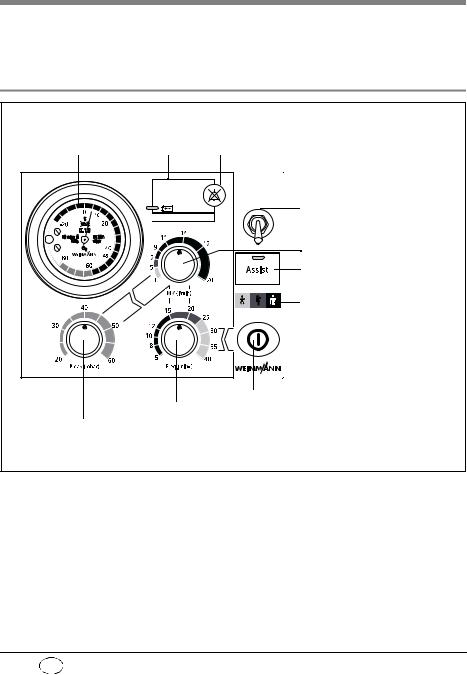
Control panel MEDUMAT Standard a
1 Ventilation pressure gauge 2 Alarm panel 3 Alarm acknowledgement
 Stenosis
 Disconnection
 < 2,7 bar O2
 No assist
|
MEDUMAT |
|
|
Standard a |
|
|
Air Mix |
4 Air Mix/No Air Mix switch |
|
No Air Mix |
5 Minute volume regulator |
|
6 On/Off switch, |
|
|
assisted ventilation |
|
|
7 Colour code |
|
|
Toddler (yellow, 10 kg to 30 kg) |
|
|
Child (orange, 30 kg to 60 kg) |
|
|
Adult (brown, 60 kg to 110 kg) |
8 ON/OFF switch
9 Ventilation frequency regulator
10Max. ventilation pressure regulator
4 EN Overview
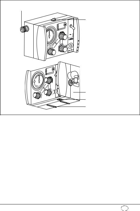
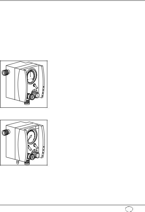
MEDUMAT Standard a connections
11 Pressure gas connection
12 Catch for STATION MEDUMAT wall mounting
 I
I

 13 Connection for ventilation tube

 14 Pressure gauge hose connection
 15 Relief valve
16 Dust cover
17 Mixed air filter
 12 Catch for STATION MEDUMAT wall mounting
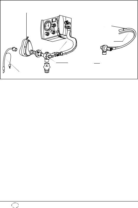
MEDUMAT Standard a device combinations
18 Ventilation mask
Disposable hose system
 19 Ventilation hose
or

 20 Pressure gauge hose 21 Filter
22 Hose casing
23 Patient valve
 24 PEEP valve
25 Tube
6 EN Overview
1.2 Symbols used on the ventilator
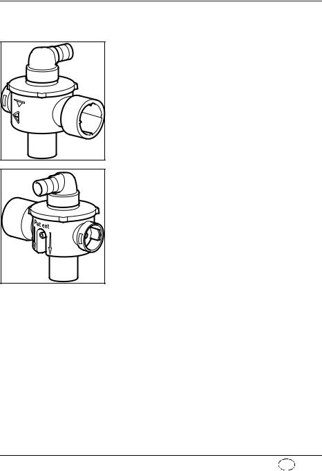
Patient valve
The symbol  on the patient valve indicates that the lip and valve membranes in the expiration and spontaneous breathing arms must be changed immediately if they are crinkled, sticky or misshapen. Under no circumstances continue to use the patient valve for ventilation in this case, as malfunctions are likely (note “7.4 Check of patient valve“ on
page 48).
The symbol  indicates the correct position for insertion of the lip membrane.
When connecting the patient valve, take care to ensure that the direction of respiratory gas flow is correct.

MEDUMAT Standard a
|
1 |
||||
|
2 |
||||
|
3 |
||||
|
I |
||||
|
7 |
6 |
5 |
4 |
|
|
1 |
Inlet 2,7 — 6 bar O2. |
|||
|
2 |
Tube system connection |
|||
|
3 |
Maximum pressure ≤100mbar |
|||
|
Safety check and servicing label |
||||
|
Safety check label: (in Germany only) marks when the next safety |
||||
|
4 |
check as per §6 of the German law relating to users of medical |
|||
|
devices is required. |
||||
|
5 |
Servicing label: indicates when the next service is due. |
8 EN Overview
MEDUMAT Standard a device information plate
|
SN |
Serial number of device |
|
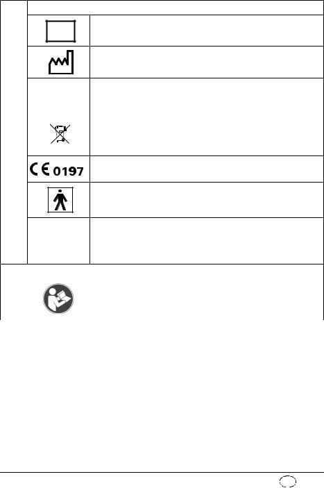
Date of manufacture |
|
Direct voltage |
||||||||||
|
6 |
3,6 V lithium battery |
|||||||||
|
Do not dispose of device in domestic waste |
||||||||||
CE symbol (confirms that the product conforms to the applicable
European directives)
Type BF application part
Degree of protection
– against the ingress of solid particles IP24 – against access to hazardous parts
– against the ingress of water with a harmful effect
Other markings
|
7 |
Follow instructions for use |
|

2. Description of ventilator
2.1 Uses
The MEDUMAT Standard a is an automatic (shortterm) ventilator with the option of assisted ventilation.
You can use MEDUMAT Standard a:
•to revive patients at the site of the emergency
•on a longer term basis in more protracted emergencies, e.g. fires.
You can use MEDUMAT Standard a while transporting patients:
•between the various rooms and departments of a hospital;
•between the hospital and other premises;
•in emergencies;
•when transport over a considerable distance is planned.
MEDUMAT Standard a:
•is designed to provide controlled ventilation to persons of approx. 10 kg body weight or more, or in the case of assisted ventilation, of approx. 15 kg body weight or more.
•is used to treat respiratory arrest;
•can be preset to parameters that ensure evenly balanced ventilation provided that the selected maximum ventilation pressure Pmax is not exceeded.
•can be supplied with additional modules for aspiration and oxygen inhalation. (N.B.
|
10 |
EN Description of ventilator |
![]()
MEDUMAT Standard a cannot be used as a ventilator simultaneously with these modules.)
2.2 Owner/operator and user qualification
As an owner/operator or user, you must be familiar with the operation of this medical device. Observe the legal requirements for operation and use (in Germany, the regulations governing owner/operators of medical devices apply in particular). Basic recommendation: get a person authorized by Weinmann to provide you with proper instruction about the handling, use and operation of this medical device.
2.3 Ventilation function
MEDUMAT Standard a operates within a pressure range of 2.7 to 6 bar and at a flow rate of not less than 70 l/min O2. It has an in-built power pack.
It uses high-pressure, medicinal-grade oxygen. An external pressure reducer brings this down to the required operating pressure. The oxygen supply is fed in at input valve.
Both the infinitely variable ventilation frequency and the inspiration/expiration ratio of 1:1.67 in the case of controlled ventilation are regulated by internal electronic control mechanisms.
The gas for inspiration is routed to the patient through the ventilation tube via the patient valve and the ventilation mask or hose. A lip membrane
|
Description of ventilator EN |
11 |
in the patient valve ensures that the expiration gas can be exhaled through the expiration arm.
Regardless of the ventilation mode selected, the patient has the option of breathing spontaneously between ventilation strokes via the patient valve. In this case, the patient draws air for breathing from the ambient air.
With the Air Mix setting, in the case of mechanical ventilation, atmospheric air is admixed to give an O2 concentration generally of between 55 % and 85 % at 10 mbar ventilation pressure (note “11.5 O2 content when using Air Mix“ on page 72).
In certain indications and in cases where the surrounding atmosphere is contaminated, you can switch to No Air Mix and ventilate with pure oxygen.
The injector unit is switched off when switching from Air Mix to No Air Mix. This increases minute volume which can result in the set pressure limit being exceeded and a stenosis alarm (Stenosis) being triggered. In this case, set minute volume correspondingly lower.
In the opposite instance, in other words when switching from No Air Mix to Air Mix, the injector unit is switched on. This reduces minute volume which can lead to the set pressure limit being undershot. In this case, set minute volume correspondingly higher.
|
12 |
EN Description of ventilator |
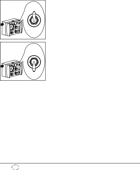
2.4 Controlled ventilation
Mandatory ventilation stroke: the device, not the patient, determines the time of the next breathing stroke.
After being switched on, the MEDUMAT Standard a is automatically in Controlled Ventilation mode. This administers mandatory ventilation strokes to the intubated patient according to the ventilation values set on the device.
2.5 Assisted ventilation
Triggered ventilation stroke: the patient can trigger a ventilation stroke by his own breathing efforts.
IPPV: intermittent positive pressure ventilation (= controlled ventilation).
In addition to Controlled Ventilation mode, the MEDUMAT Standard a also has an Assisted Ventilation mode.
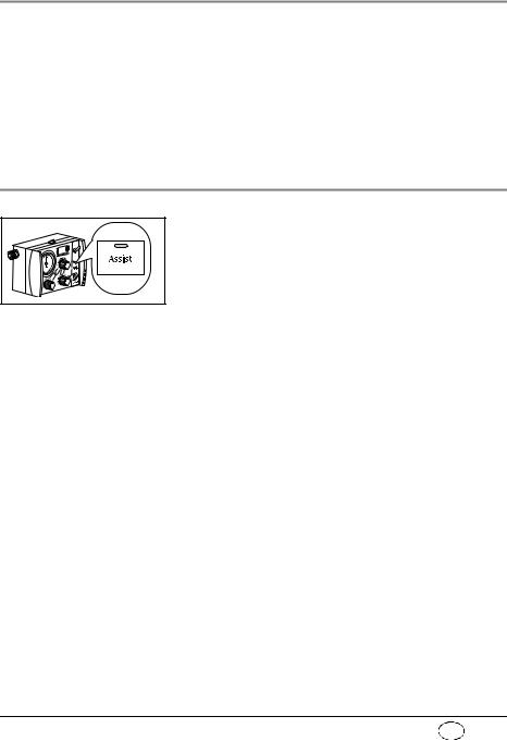
After you have switched on Assisted Ventilation mode by pressing the Assist key, a flashing green LED indicates this mode.
The patient now has the option of triggering a triggered ventilation stroke within a time window of 40 % of expiration. To do so, the patient must generate a flow of over 6 l/min. by his own breathing efforts.
If the breathing efforts of the patient are not sufficient to trigger, the patient automatically receives a mandatory ventilation stroke at the end of the time window, so that the set minute volume is guaranteed.
With this function, the ventilation strokes of the device can be synchronised with the breathing efforts of the patient.
Between the mandatory ventilation strokes of the device, the patient has the option of breathing in air from the surrounding atmosphere via the patient valve.
|
Description of ventilator EN |
13 |
If the patient does not trigger the device, an alarm is triggered. The patient continues to receive controlled ventilation.
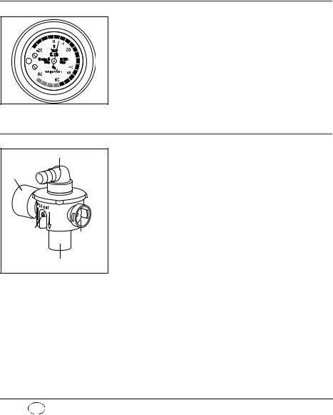
2.6 Check ventilation curve
The ventilation curve is checked at ventilation pressure gauge.
2.7 Patient valve
Respiration hose connection
Expiration tube
|
Connection |
Sponta- |
|
|
for pressure |
||
|
neous |
||
|
gauge tube |
||
|
breath- |
||
|
Mask/tube connectioning tube |
The gas for inspiration is channelled into the patient’s airways through the patient valve.
It is designed so that spontaneous breathing is possible, even if the MEDUMAT Standard a fails, regardless of which ventilation mode you have selected.
|
14 |
EN Description of ventilator |
2.8 Modules
Modules with additional functions can be attached to MEDUMAT Standard a.
Please refer to the directions for use enclosed with the modules for exact details of how to fit and operate these. It is essential to read these directions carefully before using the modules. The most important points are listed below:
Oxygen MODULE
The Oxygen MODULE enables you to apply oxygen inhalation.
Put the switch marked O2 into the “I“ position. Select the desired oxygen volume by turning the knob marked l/min to a setting between 0 and 15 l/min. You can check this setting on the volume manometer.
Combi MODULE
The Combi MODULE enables you to apply both oxygen inhalation and suction.
For inhalation put the switch marked O2 into the “I“ position. Select the desired oxygen volume by turning the knob marked l/min to a setting between 0 and 15 l/min. You can check this setting on the volume manometer.
For suction switch the tumbler marked Vac to the “I“ position. The suction pressure is locked at -0.5 bar.
|
Description of ventilator EN |
15 |

3. Safety instructions
3.1 Safety regulations
For your own safety, the safety of your patients, and to comply with the requirements of EU Directive 93/ 42/EEC, please observe the following points:
General
•Please read the directions for use carefully. They are an integral part of the ventilator and should be available for reference at all times.
•Before starting to work with
MEDUMAT Standard a, you must understand how to operate it.
•Please comply with section “6. Hygienic preparation“ on page 39 to prevent infection or bacterial contamination.
•MEDUMAT Standard a should be used only by medically qualified personnel who have had training in ventilation techniques. Incorrect use can cause severe physical injury.
•It is advisable for you to have servicing and repairs carried out only by the manufacturer, Weinmann, or by qualified technicians expressly authorized by Weinmann.
•If third-party items are used, functional failures may occur and fitness for use may be restricted. Biocompatibility requirements may also not be met. Please note that in such cases, any claim under warranty and liability will be voided if neither the accessories nor genuine replacement
|
16 |
EN Safety instructions |

parts recommended in the instructions for use are used.
•MEDUMAT Standard a should be used only for the purposes for which it is designed (note “2.1 Uses“ on page 10).
•MEDUMAT Standard a is not designed for use under hyperbaric conditions (pressure chamber).
•MEDUMAT Standard a should never be used with flammable anaesthetics.
•In the case of use in poisoned or low-oxygen atmospheres, do not operate the MEDUMAT Standard a with the „Air Mix“ setting or in Assist mode.
•A back-up ventilator should always be available in case of technical failure.
Warning: • Modifications may not be made to the device. Have modifications to the device carried out only by the manufacturer, Weinmann, or by specialist staff expressly authorized by the manufacturer.
Oxygen
Highly-compressed oxygen can lead to spontaneous explosive reactions in combination with flammable substances (fat, oil, alcohol, disinfectants, etc.):
•All screw connections and other components of the ventilator must be kept absolutely free of oil and grease.
•Always wash your hands before starting to work on the oxygen supply.
•Smoking and open flames are strictly prohibited in the vicinity of all fittings containing or transporting oxygen.
•During assembly and when changing the oxygen cylinder, only hand pressure should be used
|
Safety instructions EN |
17 |

when tightening the screw connections to the cylinder and to the pressure reducer. Never use tools for this purpose. Excessive tightening damages the screw threads and seals and can cause leaks.
•Protect oxygen cylinders from accidental falls. If a cylinder falls, the pressure reducer or the valve may break off and cause a violent explosion.
Important note • Always open the valve of the oxygen cylinder slowly to prevent pressure damage to the other fittings.
•The oxygen cylinder should never be completely emptied as this may allow moisture-containing air to enter the cylinder and cause corrosion.
Operation
•Both the patient and the ventilator must be kept under constant observation during ventilation.
• Make sure that neither the expiration tube nor the spontaneous breathing tube on the patient valve is blocked or impeded in any other way, e.g. by the patient’s position.
•MEDUMAT Standard a must never be used simultaneously with a module as this would make it impossible to work to the selected parameters.
Note • Disposable hose systems WM 28110 (2 m) and WM 28188 (3 m) are only intended to be used once.
Software
•Extensive validation tests have been performed to minimize risks arising from software errors.
|
18 |
EN Safety instructions |

Accessories
•Please protect the silicone and rubber components against UV radiation and prolonged exposure to direct sunlight, as this can make them brittle and friable.
|
Safety instructions EN |
19 |
4. Installation
A permanent mounting is usually necessary only when MEDUMAT Standard a is installed as a fixture in rescue vehicles, helicopters or aircraft. In these cases either the STATION MEDUMAT or installation kits are available as accessories.
If MEDUMAT Standard a is supplied complete with carrying platform, it is ready for use and requires no further installation. Separate directions for use are supplied with the carrying platform.
Functional tests must be carried out after installation (note “7. Functional checks“ on page 45).
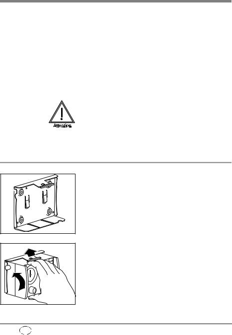
4.1 Wall mounting for STATION MEDUMAT
The wall mounting for the STATION MEDUMAT should be installed at an appropriate place, e.g., on a side panel inside the vehicle. Please refer to the sheet enclosed with the STATION MEDUMAT for details of dimensions and the installation procedure.
To place MEDUMAT Standard a in the wall mounting, first insert the slides on the underside of the ventilator into the matching grooves in the STATION MEDUMAT and then press the MEDUMAT Standard a inwards until the catch snaps into the fastening at the top of the STATION MEDUMAT.
20 EN Installation
![]()
4.2 Installation kit for the wall mounting
A number of kits are available for installing a wall mounting, e.g. on a panel inside a vehicle. The kit size varies according to the number of modules attached to the MEDUMAT Standard a.
Please refer to the sheet enclosed with each installation kit for details of dimensions and installation procedure.
4.3 Connecting up the oxygen cylinder
Wash your hands thoroughly before any work on the oxygen supply. Hydrocarbon compounds (e.g. oils, greases, alcohol for cleaning, disinfectants, hand cream or sticking plaster) can lead to explosive reactions if they come into contact with highly-com- pressed oxygen.
Never use wrenches or similar tools to tighten or loosen the screw connections.
Removal of empty cylinder
1. Close the valve of the oxygen cylinder.
Switch on MEDUMAT Standard a with ON/OFF switch. This exhausts any residual oxygen and depressurizes the ventilator. Wait until the pressure gauge on the pressure reducer shows 0 bar oxygen content before uncoupling the screw connection by hand.
2. First switch off MEDUMAT Standard a again.
3. Then loosen the screw connection to the cylinder.
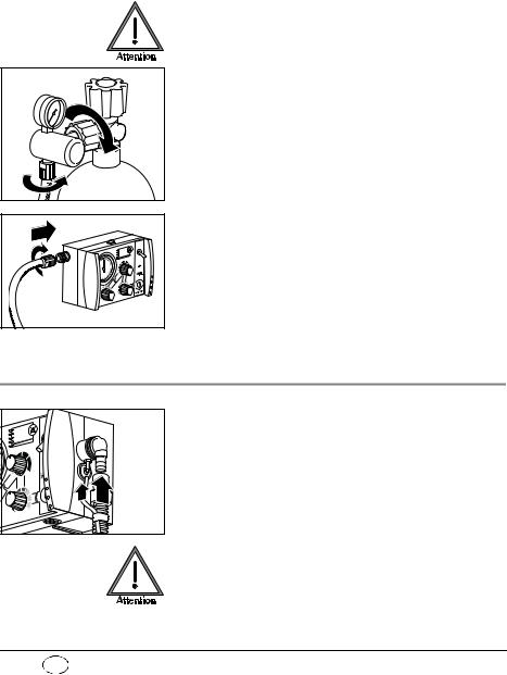
Connecting up new cylinder
1.First open the valve of the new oxygen cylinder and close it again quickly. This will blow out any particulate matter.
Keep the valve opening away from the body, making sure that neither yourself or other persons can be injured by escaping particles!
2. Next couple the pressure reducer to the valve on the oxygen cylinder with the fluted connecting nut. Tighten up the nut by hand.
3. If the pressure hose is not already connected to the exit valve of the pressure reducer, make this connection with the G 3/8 connecting nut.
4. Screw the other end of the pressure hose on to pressure gas connection on the
MEDUMAT Standard a if this has not yet been done.
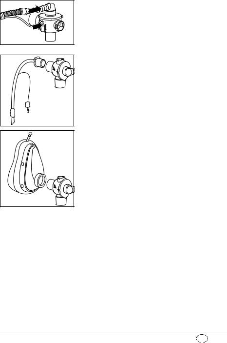
4.4 Ventilation hose
1. Slide the pressure gauge hose onto the connection.
2. Slide the ventilation tube onto the connection. Make sure that the pressure gauge hose already connected is not kinked. If necessary, turn the ventilation tube while sliding on as appropriate.
Do solely grasp the ventilation tube by its end (position of arrow in adjacent drawing). Otherwise the hose may become damaged or tear.
22 EN Installation
Position 
>PSU<134°
3.Plug the other end of the ventilation tube and the pressure measurement tube onto the patient valve.
4.If the patient is intubated, insert the patient valve into the tube,
or
Position 
>PSU<134°
if a mask is being used for ventilation, insert the patient valve into the connector on the mask. (This is identical with the connector on the tube.)
HME-Filter
If a heat and moisture exchanger (HME) filter is required, this should be installed between the pa- tient-side connector on the patient valve and the tube or mask.
Always follow the manufacturer’s directions for use.
 Loading…
MEDUMAT стандарт – описание прибора и инструкция по эксплуатации.
Прибор искусственного дыхания MEDUMAT стандарт WM 22500
Для начала просмотра выберите “Нажмите, чтобы просмотреть в полноэкранном режиме”.
В некоторых браузерах могут быть заблокированы всплывающие окна, что может вести к нарушению просмотра в полноэкранной версии.
В полноэкранной версии возможен полноэкранный поиск и интерактивное оглавление.
Вернуться на главную страницу Образовательного портала
Ссылка на официальную страницу производителя
Ссылка на видео с канала YouTube — Медумат с условиях СМП
-
Contents
-
Table of Contents
-
Troubleshooting
-
Bookmarks
Quick Links
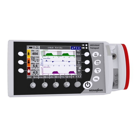
MEDUMAT Transport
Ventilator
Instructions for Use for Devices from Software Version 6.7
Related Manuals for Weinmann MEDUMAT Transport
Summary of Contents for Weinmann MEDUMAT Transport
-
Page 1
MEDUMAT Transport Ventilator Instructions for Use for Devices from Software Version 6.7… -
Page 2: Table Of Contents
Hygienic preparation ..109 Monitoring ventilation ..51 MEDUMAT Transport ..109 5.10 Performing inhalation ..53 Hose systems .
-
Page 3
Maintenance ….129 12.1 MEDUMAT Transport ..129 12.2 Sending in device … . 130 12.3 Batteries . -
Page 4: Overview
1. Overview Connections on MEDUMAT Transport 1 Alarm LED 2 USB interface 3 O2/AIR inlet 4 O2/AIR inlet/ outlet 5 Filter compartment cover, air inlet 6 Ventilation connection terminal 9 External power supply unit 8 DC connection 7 Rechargeable battery…
-
Page 5
Ventilation connection terminal 1 CO measuring hose connection 2 PEEP control hose connection 3 Pressure-measurement hose connection 5 BiCheck flow sensor connection line connection 4 Ventilation hose/inhalation adapter connection 1 CO measuring hose connection 4 Ventilation hose/inhalation adapter connection The CO measuring hose of the patient hose sys- The ventilation hose of the patient hose system or tem is attached to this connection via the connec-… -
Page 6
Controls of MEDUMAT Transport 1 Context-dependent 11Function buttons for function button emergency ventilation 2 Alarm mute button with 3 Context-dependent function button 4 Function button for main menu 5 Context-dependent function button 6 Function button for 100% O 7 Function button for… -
Page 7
Display of MEDUMAT Transport 1 Battery/Line operation indicators 10 Mode indicator 9 Info field 8 Numeric measurement display 7 Battery charge status 6 Numeric mea- surement display 2 Function indicator for 5 Function indica- context- tor for context- dependent dependent func-… -
Page 8
2 Water filter for CO measurement The blanking plug (Luer lock) is used to seal off the CO outlet if your MEDUMAT Transport is not The water filter protects the measuring chamber equipped with CO measurement or this is not of the MEDUMAT Transport against moisture and activated. -
Page 9
Hygiene input filter (optional) 1 Filter grommet 2 Filter mount 3 Hygiene input filter 1 Filter grommet 3 Hygiene input filter Protects the device from viral and bacterial Holds the suction filter in position. contamination. 2 Filter mount For installing a hygiene input filter in the device. Overview… -
Page 10
Inhalation adapter 1 Cover 2 Inhalation mask 3 Inhalation adapter 1 Cover 3 Inhalation adapter For connecting an inhalation mask to the device. Blocks the top two measuring ports on the device during inhalation. 2 Inhalation mask The patient inhales oxygen through the inhala- tion mask. -
Page 11
MEDUMAT Transport Main menu MEDUMAT Transport Main menu A A ctivate automatic alarm limits Automatic alarm limits MVe n MVe p Apnea Alarm limits etCO etCO P P ressure, flow Pressure, CO Pressure, flow, CO Pressure, flow, measurements Curves Pressure, CO… -
Page 12
Mode menu BiLevel + ASB aPCV CPAP + ASB PRVC + ASB IPPV S-IPPV SIMV + ASB Inhalation Pre-oxygenation Symbols used on the display Symbol Meaning Emergency mode – Infant (up to approx. 1 year) Emergency mode – Child (approx 1-12 years) Emergency mode –… -
Page 13
Symbol Meaning Tick box: option activated Radio button: function selected Navigate upwards Navigate downwards Increase value Decrease value Confirm your selection Navigation knob active Bluetooth connection: – Symbol is gray when connection has been activated – Symbol is blue during communication Acoustic alarm output activated Acoustic alarm output deactivated Alarm volume set to <… -
Page 14
Symbol Meaning Acoustic alarm output permanently muted (NVG mode only) Time Trigger time slot Overview… -
Page 15
Function of the controls during ventilation Depending on the ventilation mode selected, you can set the following ventilation parameters using the controls: Ventilation Control Control Control Control Navigation Function Function Function mode knob 1 knob 2 knob 3 knob 4 knob 5 button 6 button 7… -
Page 16
Ventilation Control Control Control Control Navigation Function Function Function mode knob 1 knob 2 knob 3 knob 4 knob 5 button 6 button 7 button 8 I:E and PEEP pMax Freq. Selection/ Δ pASB Trigger Mode SIMV + ASB Confirmation Flow Mode Inhalation… -
Page 17
Special markings MEDUMAT Transport 1 MEDUMAT Transport type plate 2 Voltage input 9 Cover of USB interface 8 Filter compartment cover 7 O2/AIR inlet 6 O2/AIR inlet/outlet 3 STK and service label Battery 5 Ventilation hose connection 4 Follow the instructions for use… -
Page 18
Symbol Meaning DC voltage Minimum and maximum current Do not dispose of the unit in the household waste. Type of protection against electric shock: protection class II device Protection against ingress of water IPX4 CE mark (confirms that the device complies with the applicable European Directives). -
Page 19
Symbol Meaning Volume flow rate / AIR 270 – 600 kPa 80 – 150 l/min Input 2.7 bar–6 bar O or sterile compressed air Consult instructions for use Rechargeable battery type plate Do not dispose of the unit in the household waste. Do not subject the unit to hard knocks or shocks. -
Page 20
Consult instructions for use Do not reuse Labeling on the packaging Symbol Meaning MEDUMAT Transport: Serial number of the unit Permissible storage temperature: -30°C to +70°C Permissible humidity for storage: up to 95% relative humidity RH % 0-95 Safety information in these instructions for use… -
Page 21: Description
The MEDUMAT Transport is an automatic oxygen ventilator with additional preoxygen- ation and monitoring functions (pressure, flow and CO MEDUMAT Transport is used for the controlled and assisted, as well as invasive and non-inva- sive, ventilation of adults, children, and infants. In the case of volume-controlled ventilation, tidal volumes of 50 ml or more are possible.
-
Page 22: Operator And User Qualification
2.3 Operator and user qualification MEDUMAT Transport must only be used by persons who can verify that they have the following qualifications: • A medical qualification and training in ventilation techniques • Training in the use of the MEDUMAT Transport by a person authorized by WEINMANN Emergency Improper use may lead to serious physical injury.
-
Page 23
Disposable hose system with reduced dead space without CO measuring hose for adults and children Hygiene input filter (optional) For ventilation in a contaminated atmosphere, MEDUMAT Transport can be used with a hygiene input filter. This protects the device from viral and bacterial contamination. Inhalation adapter The ventilation gas can alternatively be supplied to the patient via the inhalation adapter and the inhalation hose. -
Page 24: Safety Information
Please observe the section «9. Hygienic preparation» on page 109 in order to avoid infection or bacterial contamination. Warning! • Risk of injury. Only use MEDUMAT Transport if you are a qualified medical professional and have received training in respiration techniques. Improper use may lead to serious physical injury. •…
-
Page 25
Always keep the air inlet openings on the filter compartment cover or the suction inlets on the hygiene input filter clear. • Only have modifications to the unit carried out by the manufacturer, WEINMANN Emergency, or by a technician expressly authorized by WEINMANN Emergency. Caution! •… -
Page 26
Safe handling of oxygen Warning! • Risk of explosion! In combination with combustible substances (grease, oil, alcohol etc.), highly compressed oxygen may give rise to spontaneous explosive reactions. • Risk of fire! If only the O2/AIR inlet/outlet is used, close the O2/AIR inlet on the side with a suitable cap. -
Page 27
Otherwise, there is a risk of insufficient ventilation. • Do not place the patient valve of the disposable hose system with reduced dead space near the O2/Air inlet of the MEDUMAT Transport, in order to prevent the device sucking in CO •… -
Page 28
Protect silicone/rubber parts against UV light and prolonged direct exposure to sunlight to prevent them becoming brittle. • We recommend that work such as inspections and repairs should be carried out by the manufacturer, WEINMANN Emergency, or by a technician expressly authorized by WEINMANN Emergency. Safety information… -
Page 29
• If third-party items are used, functional failures may occur and fitness for use may be restricted. Biocompatibility requirements may also not be met. Please note that in such cases, any claim under warranty and liability will be voided if neither the accessories nor genuine replacement parts recommended in the instructions for use are used. -
Page 30: Installation
4. Installation As a rule, MEDUMAT Transport only has to be installed for stationary use in rescue vehicles, helicopters or aircraft. In this case, fastening sets can be supplied as accessories. If MEDUMAT Transport is supplied complete on a portable system, the unit is ready for operation and no further installation work is required.
-
Page 31
Connecting a new cylinder 1. Briefly open the valve of the new oxygen cylinder, then shut it again. This is to blow away any particles of dust. Caution! • Make sure that the patient is not connected up to the MEDUMAT Transport when you are establishing the gas supply. -
Page 32: Connecting The Hose System
Otherwise, ventilation with a connected inhalation mask, tube, or inhalation cannula could injure the patient. A reusable hose system is supplied with the MEDUMAT Transport. Alternatively, a disposable hose system and a disposable hose system with reduced dead space are also available.
-
Page 33
Notice You can remove the elbow to reduce the dead space or to adapt the hose routing to suit the patient’s position. Elbow Hose protection sleeve The tube protection sleeve is pulled over the ventilation hose with connected BiCheck flow sensor. It prevents the hose system from tangling on other items of equipment and being damaged. -
Page 34: Connecting The Inhalation Adapter
4.3 Connecting the inhalation adapter An inhalation adapter for oxygen inhalation via the MEDUMAT Transport is supplied with the unit. The inhalation mode is used for administering a defined oxygen flow of 1-10 l/min via a suitable interface. On delivery, the inhalation adapter is secured to the connection for the ventilation hose by a retaining band.
-
Page 35: Accessories From Other Manufacturers
*Not all types of humidifiers are suitable for use with MEDUMAT Transport. Always ensure that all products are compatible. **Not all types of nebulizers can be used effectively with MEDUMAT Transport. Always ensure that all products are compatible. Installation…
-
Page 36
You can use the O2/AIR inlet/outlet to connect units, modules or inhalation devices to the MEDUMAT Transport (quick connector to the front of the units). When doing so, bear in mind that the outlet gas flow reduces the efficiency of the gas supply (see «14.6 Possible O… -
Page 37: Permanent Installation Of The Unit
If you wish to install the unit on a portable system or permanently install it in a vehicle or aircraft, you require the fastening set WM 15730. The following diagram shows the method of installation. Back panel of MEDUMAT Transport Portable system Installation…
-
Page 38: Operation
5. Operation 5.1 Controls Display The display provides the following information while the unit is in use. • Progress of the current ventilation • Current measurements and alarm limits • Ventilation parameters set/to be set • Current assignment of the context-dependent function buttons and control knobs •…
-
Page 39
Context-dependent function buttons On both sides of the display there are context-dependent function buttons for calling up the following functions: Left side of the display: • Selecting emergency modes (available in every Function buttons ventilation mode): for emergency – Infant (up to approx. 1 year) ventilation –… -
Page 40
Navigation knob When a menu is open, you can use the navigation knob to navigate as follows: • Turn anticlockwise: moves the selection bar upwards in the menu • Turn clockwise: moves the selection bar downwards in the menu • Press the navigation knob: confirms selection Navigation knob When no menu is open, you can carry out the following functions:… -
Page 41: Switching The Unit On/Self-Test
57). You should change the cylinder in good time, e.g., when the pressure falls below 50 bar, to ensure a sufficiently long operating time. 3. To switch on MEDUMAT Transport, press the On/ Standby/Off button. An automatic self-test runs which includes the following sequence of steps: •…
-
Page 42
The self-test is successful when all the steps have been completed. Check that all the steps are successfully completed. Do not operate the unit if: • one of the first three steps has not been successfully completed • the last part has not been successfully completed («Fault»… -
Page 43
– Press the «New patient» button: Select the «Height» setting. The «Patient parameters» menu appears. Select the gender. Set the correct height with the context-dependent function keys or the navigation knob. Confirm the setting with «continue». Now select the appropriate ventilation mode and confirm your selection. -
Page 44: Navigating In Menus
5.3 Navigating in menus The vast majority of functions of the MEDUMAT Transport are accessed via menus. MEDUMAT Transport offers two methods of navigating in these menus: • using the navigation knob • using the context-dependent function buttons on the right of the display You can close menus at any time by pressing the Menu button again.
-
Page 45
Navigating with the context-dependent function buttons 1. First use the function buttons to select a menu (here: Main menu). 2. Select a menu item by pressing the function button (the selection bar moves downwards) or the button (the selection bar moves upwards). 3. -
Page 46: Selecting Emergency Mode
5.4 Selecting emergency mode Three modes with preset ventilation parameters are available for emergency ventilation. You can select these directly at any time during ventilation by pressing one of Emergency the function buttons twice or by pressing one of the ventilation function buttons once and then confirming with the function…
-
Page 47: Selecting A Ventilation Mode
Factory settings of the unit: Emergency mode IPPV Parameter Adult Child Infant 0 mbar 0 mbar 0 mbar PEEP 30 mbar 25 mbar 20 mbar pMax 1:1.7 1:1.7 1:1.7 10/min 20/min 30/min Frequency 500 ml 200 ml 60 ml 5.5 Selecting a ventilation mode To select a different ventilation mode, proceed as follows: 1.
-
Page 48: Changing The Ventilation Mode
5.6 Changing the ventilation mode To change the currently set ventilation mode, proceed as follows. 1. First, use the «Mode» function button to select the «Mode» menu. 2. Then use the navigation knob or the context-depen- dent function buttons on the right of the display to se- lect whether you wish to ventilate invasively or non- invasively.
-
Page 49: Selecting Additional Ventilation Functions
The saved values become available again as soon as the previous ventilation mode is reactivated. • When changing from volume-controlled ventilation to pressure- controlled ventilation, the unit adopts the preset inspiratory pressure from the operator menu. • If you have selected a volume-controlled mode, and if the tidal volume or ventilation rate has changed, the device automatically adapts the corresponding alarm limits (±…
-
Page 50: Performing Ventilation
Notice: When performing ventilation with a tidal volume Vt < 200 ml, a PEEP > 0 mbar and an inspiratory O concentration set to FiO < 70%, the inspiratory O concentration administered can deviate from the set value. Reduce the PEEP to decrease the administered inspiratory O concentration.
-
Page 51: Monitoring Ventilation
Caution! Using the elbow increases the dead space of the hose system. Take this into account when setting the ventilation parameters. Otherwise the success of treatment may be compromised. 2. Attach the mask to the hose system. 3. If necessary, introduce a Guedel oropharyngeal tube to keep the patient’s airways free. 4.
-
Page 52
Displayed measurements During ventilation, the following parameters are displayed as numbers: – O i: inspiratory O concentration measured by the unit – Vt : expiratory tidal volume/breath volume – f/(fsp): respiratory rate/number of spontaneous breaths per minute and the corresponding alarm limit –… -
Page 53: Performing Inhalation
If you have a unit equipped with CO measurement, you can vary the display as follows: – Pressure, flow – Pressure, CO – Pressure, flow, CO – Pressure, flow, measurements – Pressure, CO , measurements – Gauge (only in volume-controlled modes) 5.10 Performing inhalation Caution! The device must not be operated in combination with a nebulizer during oxygen in-…
-
Page 54: Alarm Signals
6. Select the «Inhalation» mode and confirm your selection. 7. Then select «Start ventilation» and confirm your selection. The device starts the inhalation. 5.11 Alarm signals Alarm priority MEDUMAT Transport classifies alarms into the following priority levels: • high priority • medium priority • low priority If two or more alarms occur simultaneously, alarms with the currently highest priority are displayed cyclically.
-
Page 55
Display of alarms MEDUMAT Transport displays alarms as follows: • High priority – LED flashes red – «High priority» alarm sounds every 8 seconds – Alarm text appears in info field; info field flashes Info field – Corresponding alarm limit in the measurement field flashes red •… -
Page 56: Ventilation With Breathing System Filters (Not Supplied With The Unit)
Notice • Following the start of ventilation, all alarms are automatically muted for 120 seconds. This is with the exception of the technical alarms «Supply pressure < 2.7 bar», «Battery almost empty», and «Device malfunction», which cannot be muted. During this time, visual alarms are still displayed. •…
-
Page 57: Calculating The Oxygen Level/Operating Time
149). This gives: 1000 l ————————- — × ————— — Ventilation operating time (min) 88 min 1 h 28 min 11.3 l/min 100% If MEDUMAT Transport is operated with an O concentration less than 100%, the operating time will increase correspondingly. Operation…
-
Page 58: Alternative Ventilation
2. Attach the ventilation bag, e.g., COMBIBAG WM 11000 from WEINMANN Emergency and perform manual ventilation. Oxygen failure If the oxygen supply fails or no medical oxygen is available, the MEDUMAT Transport can also be operated with sterile compressed air or concentrator oxygen (see «Options» on page 91).
-
Page 59: Battery Management
WM 28937. MEDUMAT Transport can be operated from an external power supply when the battery is empty. The battery is charged while the unit is in operation but charging takes longer than when the unit is switched off.
-
Page 60
The charging status is only indicated when the external power supply is connected, since only then is it possible to actually charge the battery. When MEDUMAT Transport is off, the charging status is shown by the charging indicator. When MEDUMAT Transport is on, the charging status is shown by both the charging indicator and the capacity indicator. -
Page 61
Battery missing or (current charge level) faulty Charging batteries MEDUMAT Transport starts charging the battery automatically, as soon as the following conditions are met: • External power supply with at least 12 V DC is connected • The battery is not full (<95% charge) •… -
Page 62
Ending battery charging MEDUMAT Transport automatically determines the optimum point at which to end charging by measuring and evaluating the charging curve and battery temperature. As soon as charging has ended, the charging indicator glows green continuously. Interrupting battery charging Battery charging is continuously monitored by MEDUMAT Transport. -
Page 63: Ventilation Modes
6. Ventilation modes You can select different ventilation modes in the «Mode» menu (see «5.5 Selecting a ventilation mode» on page 47). This section describes: • Classification of the ventilation modes (see «6.1 Classification of the ventilation modes» on page 63) •…
-
Page 64
The following ventilation modes are available in the unit: Spontaneous Control parameter Controlled ventilation Assisted ventilation respiration Pressure BiLevel + ASB, aPCV CPAP + ASB Pressure + Volume PRVC + ASB S-IPPV Volume IPPV SIMV + ASB Setting ventilation parameters can cause the classification of the ventilation modes to change. -
Page 65: Important Ventilation Parameters
6.2 Important ventilation parameters Unit behaviour/ Ventilation parameter Explanation Special features In certain circumstances it may no longer be possible to achieve breath volume with volume-controlled ventilation. Tidal volume (breath volume) If airway pressure reaches the set limit pMax, it will be limited to the value pMax (pressure-limited ventilation).
-
Page 66: Additional Functions And Safety Functions
6.3 Additional functions and safety functions NIV: Non-Invasive Ventilation (Mask ventilation) This additional function can also be activated in all pressure-controlled modes and in the CPAP + ASB mode.The leakage alarm is deactivated. The unit uses optimized trigger algorithms for non-invasive ventilation. If non-invasive ventilation is activated, only the ventilation modes BiLevel + ASB, aPCV, PCV, and CPAP + ASB available for this are shown in the «Mode»…
-
Page 67
Ventilation modes» on page 63). Caution! In the case of oxygen inhalation, check that the inhalation hose is connected and the measuring ports on the MEDUMAT Transport are blocked (see «4.3 Connecting the inhalation adapter» on page 34). Ventilation modes… -
Page 68: Pressure-Controlled Ventilation Modes
6.4 Pressure-controlled ventilation modes Caution! Ventilation pressure is limited to pMax in the pressure-controlled modes (pressure limitation). A high-priority alarm is triggered when this pressure limit is reached. BiLevel + ASB BiLevel: ventilation at two pressure levels ASB: Assisted Spontaneous Breathing You can set the following ventilation values using the control knobs: Function Ventilation…
-
Page 69
Pressure pMax automated ventilation assisted respiration pInsp Pressure ramp Δ pASB PEEP Time TI=T 1/Freq. insp (spontaneous) 1/Freq. (set) The BiLevel + ASB mode is used for pressure-controlled ventilation combined with free spontaneous respiration at pressure levels pInsp and PEEP during the entire breathing cycle and for adjustable pressure support at PEEP level. -
Page 70
aPCV aPCV: assisted Pressure Controlled Ventilation Warning! • Risk of hyperventilation! Continuously monitor the patient’s measured respiratory rate and measured minute volume in order to prevent ↑ hyperventilation. To this end, set a narrow alarm limit for the alarm, in order to recognize the risk of hyperventilation in good time. -
Page 71
You can find more setting options under the menu item «Advanced ventilation parame- ters» in the «Main menu» (see «7.4 Advanced ventilation parameters» on page 87). Pressure pMax Synchronized Automated Automated ventilation automated ventilation ventilation pInsp Pressure ramp PEEP Time ΔT 1/Freq. -
Page 72
PCV: Pressure Controlled Ventilation You can set the following ventilation values using the control knobs: Ventilation Control Control Control Control Navigation Function Function Function mode knob 1 knob 2 knob 3 knob 4 knob 5 button 6 button 7 button 8 I:E and PEEP pInsp… -
Page 73
Pressure pMax pInsp Pressure ramp PEEP Time 1/Freq. (set) 1/Freq. (set) PCV mode is used for mandatory pressure-controlled ventilation with fixed pressure levels. This mode is used on patients who have no spontaneous respiration. However, a spontaneously breathing patient can breathe deeply and freely during expiration. The set maximum pressure limitation (pMax) ensures the safety of the patient. -
Page 74
CPAP + ASB CPAP: Continuous Positive Airway Pressure ASB: Assisted Spontaneous Breathing You can set the following ventilation values using the control knobs: Ventilation Control Control Control Control Navigation Function Function Function mode knob 1 knob 2 knob 3 knob 4 knob 5 button 6 button 7… -
Page 75
The ASB mode is used for pressure support of insufficient or exhausted spontaneous respiration. The patient is able to breathe spontaneously without any restriction, but is supported in his breathing effort by MEDUMAT Transport. The CPAP + ASB mode is used exclusively on patients with adequate spontaneous respiration. -
Page 76
PRVC + ASB PRVC: Pressure Regulated Volume Controlled Ventilation ASB: Assisted Spontaneous Breathing You can set the following ventilation values using the control knobs: Ventilation Control Control Control Control Navigation Function Function Function mode knob 1 knob 2 knob 3 knob 4 knob 5 button 6… -
Page 77
Pressure pMax Safety pPlat pInsp (variable) margin 5 mbar Increments max. 3 mbar PEEP Time volume-controlled pressure-controlled pressure-controlled mechanical breath mechanical breath mechanical breath 1/Freq. (set) 1/Freq. (set) The controlled ventilation mode PRVC + ASB combines the advantages of both pressure- controlled ventilation and volume-controlled ventilation. -
Page 78: Volume-Controlled Ventilation Modes
6.5 Volume-controlled ventilation modes Warning! Risk of inconsistent volume once pressure limitation pMax is reached! Monitor the patient continuously throughout volume-controlled ventilation modes and change the setting parameters if necessary. Once the pressure limitation is reached, a high- ↑ priority alarm (airway pressure ) guarantees the safety of the patient.
-
Page 79
Pressure pMax automated ventilation automated ventilation pPlat PEEP Time 1/Freq. (set) 1/Freq. (set) The IPPV mode is used for mandatory volume-controlled ventilation with a fixed tidal volume. This mode is used on patients who have no spontaneous respiration. However, a spontaneously breathing patient can breathe deeply and freely during expiration. -
Page 80
S-IPPV S-IPPV: Synchronized Intermittent Positive Pressure Ventilation Warning! • Risk of hyperventilation! Continuously monitor the patient’s measured respiratory rate and measured minute volume in order to prevent ↑ hyperventilation. To this end, set a narrow alarm limit for the alarm, in order to recognize the risk of hyperventilation in good time. -
Page 81
You can find more setting options under the menu item «Advanced ventilation parameters» in the main menu (see «7.4 Advanced ventilation parameters» on page 87). Pressure synchronized automated automated ventilation ventilation pMax pPlat PEEP Time ΔT 1/Freq. (current) 1/Freq. (set) Synchronized time slot The S-IPPV mode is used for volume-controlled ventilation with a variable mandatory minute volume MV. -
Page 82
SIMV + ASB SIMV: Synchronized Intermittent Mandatory Ventilation ASB: Assisted Spontaneous Breathing You can set the following ventilation values using the control knobs: Ventilation Control Control Control Control Navigation Function Function Function mode knob 1 knob 2 knob 3 knob 4 knob 5 button 6 button 7… -
Page 83
Pressure pMax automated ventilation assisted synchronized automated spontaneous ventilation respiration spontaneous pPlat respiration ΔpASB PEEP Time ΔT 1/Freq. (current) 1/Freq. (set) Synchronized time slot The SIMV + ASB mode is used for volume-controlled ventilation with a fixed mandatory minute volume MV. The patient can breathe spontaneously between the mandatory mechanical breaths and thereby increase the minute volume. -
Page 84: Main Menu
7. Main menu In the main menu, you can optimize the unit’s settings to suit the particular operating conditions. The main menu can be called up at any time using the «Main menu» function button. To navigate in the menu, you can use either the navigation knob or the context-dependent function buttons on the right of the display (see «5.1 Controls»…
-
Page 85: Alarm Limits
Automatic alarm calculation for the Apnea alarm Depending on the set percentage, the Apnea alarm is set to 4 (10%), 5 (20%) or 6 (30%) respiratory periods. The length of a respiratory period is 60/f in seconds, i.e., with a measured respiratory rate of, for example, 15/min, the increments for the Apnea alarm limit are 16 s, 20 s, and 24 s.
-
Page 86: Curves
7.3 Curves In this menu, you can vary the display for monitoring ventilation. You can make the following settings: Parameters Setting range Pressure, flow Pressure, CO Pressure, flow, CO Curves Pressure, flow, measurements (Units equipped with measurement) Pressure, CO , measurements Pressure gauge (only available in volume- controlled modes)
-
Page 87: Advanced Ventilation Parameters
7.4 Advanced ventilation parameters To achieve optimum results during transport ventilation, you can configure settings in the «Advanced ventilation parameters» menu, depending on the particular mode selected. The non-selectable functions in a particular ventilation mode are not shown. Pressure ramp With this function you can set how quickly the inspiratory ventilation pressure should be reached.
-
Page 88
Notice: How quickly the set flow is actually reached depends on the patient, any leakage (NIV) and on the set ventilation parameters. Flow progress With this function you can set the flow progress. You can make the following settings: Parameters Setting range decreasing Flow progress… -
Page 89: Apnea Ventilation Parameters
ventilation. In contrast, at a setting of 100% Te, the patient has the possibility of triggering a mechanical breath at any point in the whole expiration time. Alternatively, you can also set the trigger time slot on the right in the display, using the trigger time slot function key. Alternatively, you can also set the trigger thresholds on the right in the display, using the trigger thresholds function button.
-
Page 90: Audio/Video
7.6 Audio/Video This menu can be used to set the display brightness, alarm volume, and alarm LED: • Display brightness: Here you can set the display bright- ness for day colors, night colors, and in NVG mode sep- arately. • Alarm volume: Here you can set the volume of all the alarms.
-
Page 91: Options
Parameters Setting range Brightness/NVG (only when NVG option is 10%-100% enabled) 50%-100% Volume 0%-100% (only when NVG option is enabled) Alarm LED (only when NVG option is 100% enabled) 7.7 Options configuration In this menu, you can activate CO suction. You can only access this menu if you have a unit equipped with CO measurement.
-
Page 92
In the menu, you can select which unit of measurement the CO concentration should be displayed in. You can make the following settings: Parameters Setting range mmHG Unit Vol% Date, time In this menu, you can set the current date and time. You can make the following settings: Parameters Setting range… -
Page 93
With the Bluetooth connection activat- ed, an application documentation system can connect to MEDUMAT Transport in order to retrieve application data. For this you need the bluetooth pin 6398 displayed in this menu. This menu only appears if the data communication option has been enabled. -
Page 94: Night Colors
Hygiene input filter (optional) In this menu you can reset the hygiene input filter counter after a filter change. The remaining life of the hygiene in- put filter is shown in percent and is 100% when you have changed the hygiene input filter. Requirements for this function: •…
-
Page 95
You can activate the NVG mode here. When the NVG mode is activated, the device behaves as follows: • Alarm LED deactivated • Acoustic alarm output for all alarms permanently deac- tivated • Coloring of the display optimized for night vision devices •… -
Page 96: Operator Menu
8. Operator menu In the operator menu, you can optimize the unit’s settings to suit the particular operating conditions. The operator menu can be opened as follows when the device is started 1. Switch on the device 2. Then press the two lower context-dependent function keys simultaneously (see image on left).
-
Page 97
1. To call up a specific page of the operator menu, turn the navigation knob until the required page is dis- played. 2. Press the navigation knob. The first menu item of the selected page is highlighted in blue. 3. In order to call up a menu item on a page, turn the nav- igation knob until the selection bar is on the required menu item. -
Page 98
MEDUMAT Transport operator menu Enter operator menu Change operator password Password Page Enter service menu IPPV BiLevel + ASB Edit ventilation settings CPAP + ASB Ventilation Modes Edit alarm limits SIMV + ASB S-IPPV PRVC + ASB aPCV Pre-oxygenation Inhalation… -
Page 99: Password Page
8.1 Password Page Before you enter the access code, the current software ver- sion of the unit is displayed on the start screen (Password Page) of the operator menu. The operator menu is protect- ed by a four-digit access code. On delivery, the access code for the operator menu is «0000».
-
Page 100
Notice: If a ventilation mode is already deactivated , you cannot call up its presets. If you have selected and confirmed the «edit presets» field, you enter the «Edit ventilation settings» submenu for the required ventilation mode. This submenu is divided into the patient groups Infant, Child, and Adult. -
Page 101: File Export/Import
The following data records are available to export: • Service Files: Files are saved in the Service Files which can be of use to the WEINMANN Emergency Technical Service or WEINMANN Emergency authorized service agents on servicing. • Mission Logs: Mission Logs contains the session data of the last 60 applications.
-
Page 102
Export/import presets or screenshots To export presets or screenshots from MEDUMAT Trans- port, proceed as follows: 1. Select the «File Import/Export» page in the operator menu. 2. Insert a USB stick in the USB port of the device. Caution! Only USB sticks which conform to the USB standard 2.0 should be inserted in the USB port. -
Page 103: Software Update
4. Select the «Software Update» page in the operator menu. Notice: It can take a moment for the MEDUMAT Transport to detect the USB stick. Leave the USB stick in the device’s USB port throughout the software update. Do not remove it until the software update has completely finished.
-
Page 104
5. Press the button or the navigation knob to start the installation of the new software version on the device. 6. Follow the instructions on the display: Notice: It is not possible to install an earlier software version than is already installed on the device. If the device is not able to read the software update file, this can have the following causes: •… -
Page 105: Options
Bluetooth communication option and NVG option. You require an option code to install the Bluetooth com- munication option and NVG option. You can obtain this from the WEINMANN Emergency customer service depart- ment. If you enable the NVG option, the following menu items are activated automatically (see «8.6 User Settings»…
-
Page 106
Language In this menu item, you can set the language in which the messages are displayed. You can choose the following settings: Parameter Options Brazilian Portuguese Português brasil. (PT-BR) Czech Český (CS-CS) Chinese 汉语 (ZH-ZH) Danish Dansk (DA-DK) German Deutsch (DE-DE) Greek Ελληνικά… -
Page 107
Emergency Mode In this menu item you can specify the IPPV or BiLevel + ASB mode as the emergency ventilation mode. Vt/kg body weight In this menu item you can set the tidal volume per kilo- gram of body weight. This value is a variable used to con- vert the body height to a tidal volume (see «14.8 Calculation of body weight on the basis of body height»… -
Page 108
Dust load on filter This menu item enables you to set the hygiene input filter wear according to the level of contamination in the ambi- ent air. You can choose between the settings «normal», «high», and «very high». Select «normal» for standard conditions, and «high»… -
Page 109: Hygienic Preparation
Otherwise the unit may be damaged, causing a hazard to users and patients. Keep MEDUMAT Transport and the BiCheck flow sensor connecting lead clean by wiping with disinfectant. If using a hygiene input filter, do not remove it for wipe disinfection;…
-
Page 110: Parts And Accessories
BiCheck flow sensor. Leave the BiCheck flow sensor to drip dry for a sufficient length of time. Alternatively, you can connect the patient hose system, without the test lung, to the MEDUMAT Transport and actuate several mechanical breaths. •…
-
Page 111: Fittings
Cleaning agents containing alcohol or grease become flammable when combined with compressed oxygen and can cause explosions. Carry out hygienic preparation of the MEDUMAT Transport and the accessories used, as described in the following table. Refer to the instructions supplied with the hose system and with the disinfectant used. We ®…
-
Page 112
Reusable components Thermo- Sterili- Parts Cleaning Disinfection disinfector zation Wipe down with a MEDUMAT Transport Wipe disinfection Not permitted moist cloth permitted Wipe down with a BiCheck flow sensor lead Wipe disinfection Not permitted moist cloth permitted Clean at 95°C, as… -
Page 113
Thermo- Sterili- Parts Cleaning Disinfection disinfector zation – Rinse with water and mild soap 30°C washing cycle, – Wash at 30°C in Immersion with the addition of Velcro strap with clip the washing disinfection a suitable permitted machine (without disinfectant spinning) With a dry or moist Oxygen fittings… -
Page 114
Disposable components Thermo- Steriliza- Parts Cleaning Disinfection disinfector tion Disposable measuring tube system comprising: – PEEP control line – Pressure-measurement tube – CO measuring hose – Connector – Water filter – Y-piece (Luer lock) These are disposable parts and must not be reused. Use new parts instead. Luer lock connector Disposable Patient Hose System… -
Page 115: Function Check
Warning! If this function check reveals any faults or deviations from the specified values, you must not use the MEDUMAT Transport. Have the unit repaired by WEINMANN Emergency or an authorized dealer. You should first try to rectify the fault with the aid of the information provided in section «11.
-
Page 116: Intervals
10.1 Intervals Before each use: • Perform a function check. After each use or disassembly: • Clean, disinfect and sterilize the unit and the components (see «9. Hygienic preparation» on page 109). • Perform a function check. At least every 6 months: •…
-
Page 117: Checking The System For Leaks
2. Wet all the screw and hose connections with the solution. If bubbles form, this indicates a leak. 3. Release the pressure in the system: Close the oxygen cylinder valve. Switch MEDUMAT Transport on briefly until the contents gauge on the O cylinder indicates «0». Then switch MEDUMAT Transport off again.
-
Page 118: Checking The Patient Valve (Reusable Hose System Only)
10.3 Checking the patient valve (reusable hose system only) Caution! • Also observe the «Function check» section in the instructions for use of the «Patient Hose System» WM 66696. • Never use torn, wavy, distorted or sticky diaphragms for ventilation. Otherwise considerable malfunctions are to be expected.
-
Page 119: Performing A Function Check
OK. Switch the device off and then on again. Re- peat the function check. If the fault reoccurs, have the device repaired by WEINMANN Emergency or an authorized dealer. 11.Press all the device controls apart from the On/Off button.
-
Page 120
13.Following a prompt during the function check: Change the suction filter (see «12.6 Changing the hygiene input filter» on page 132) or the hygiene input filter (see «12.6 Changing the hygiene input filter» on page 132). 14.Confirm the change of the suction filter or the hygiene input filter. -
Page 121
Testing the power-failure alarm 1. Once the automatic function check has finished, switch to ventilation mode. 2. Pull out the battery and disconnect the charger or remove the portable system from the wall mounting (for not more than 30 seconds). If the red alarm LED flashes and an acoustic signal sounds, the power failure alarm is functioning. -
Page 122
Suction filter Change suction filter. Hygiene input filter Change hygiene input filter If, despite all your measures to rectify the faults, a component still remains marked with a red cross, please contact an authorized dealer or WEINMANN Emergency. Function check… -
Page 123: Troubleshooting
11. Troubleshooting If problems occur which cannot be rectified immediately, contact the manufacturer, WEINMANN Emergency, or your authorized dealer to have the unit repaired. Do not continue using the unit to avoid serious damage. 11.1 Troubleshooting Fault Cause Remedy MEDUMAT Transport defective Repair by manufacturer/dealer.
-
Page 124
Insert battery in device or connect screen is dark not connected to the line power. device to the line power. Switch the MEDUMAT Transport off Internal error and back on again. If the error persists: Have device repaired. No acoustic alarm output Deactivate NVG (see «NVG (Night… -
Page 125: System Alarms
11.2 System alarms Message Alarm Cause Rectification Change suction filter on Suction filter or CO measurement hose system or occlusion medium priority measuring hose blocked replace complete measurement hose system module defective, Continue ventilation without CO module defective low priority no communication or measurement;…
-
Page 126
Message Alarm Cause Rectification No unit fault; message appears, e.g., on removing unit from wall mounting or portable system or if External power supply Battery operation low priority a power failure occurs during too weak or has failed operation via the power supply unit (alarm stops automatically after 10 seconds). -
Page 127: Physiologic Alarms
11.3 Physiologic alarms Message Alarm Cause Rectification Check state of patient. high Upper limit value ↑ Check the limit value settings for high priority exceeded plausibility. Check state of patient. Lower limit value not ↓ Check the limit value settings for high priority reached plausibility.
-
Page 128
Message Alarm Cause Rectification Selected O concentration too high, Minimize leakage, select NIV e.g., during NIV add-in. ventilation with mask Activate «Compressed gas ↓ concentration High priority Sterile compressed air or supply» function (see «Allow gas gas other than medical type selection»… -
Page 129: Maintenance
German regulations governing owners/operators of medical devices (MPBetreibV §11) which is valid under German law, we as the manufacturer recommend that all accessories for use of the MEDUMAT Transport that are connected with the same be subject to a safety check (STK) every two years.
-
Page 130: Sending In Device
1. Uninstall components and accessories. 2. Clean the device, components, and accessories (see «9. Hygienic preparation» on page 109). 3. Send in the device and, if necessary, components and accessories to WEINMANN Emer- gency or a technician specifically authorized by WEINMANN Emergency. Notice…
-
Page 131: Batteries
Notice: The batteries used for MEDUMAT Transport do not have a «memory effect». Therefore you can recharge them when they are only partially discharged without reducing their capacity or life. However, in terms of their functioning even these batteries have only a limited life of at least 300 charging cycles.
-
Page 132: Filter
1. Undo the two screws in the filter compartment cover and remove the cover. Notice: Support the cover on one side with a slot-head screwdriver. This prevents the cover from jamming while you are lifting it off. 2. Remove the old suction filter with tweezers and dispose of it correctly.
-
Page 133: Storage
«Options» menu item (see «7.7 Options» on page 91). 12.7 Storage If MEDUMAT Transport is not going be used for a considerable length of time, we recommend the following procedure: 1. Clean and disinfect the unit (see «9. Hygienic preparation» on page 109).
-
Page 134: Disposal
The device packaging (cardboard box and inserts) can be disposed of as waste paper. Disposal of batteries Do not dispose of used batteries in the household waste. Contact WEINMANN Emergency or a public waste disposal authority. Maintenance…
-
Page 135: Product, Accessories
Velcro strap with clip 28964 MEDUMAT Transport without CO module WM 28300 Parts Order number MEDUMAT Transport basic unit without CO 28315 module Patient hose system without CO measurement, 28295 reusable, complete Other items supplied as with MEDUMAT Transport WM 28400 Product, accessories…
-
Page 136: Accessories
13.2 Accessories Parts Order number Oxygen cylinder, 2-liter 1822 Lightweight aluminium oxygen cylinder, 2-liter 1821 Pressure reducer OXYWAY Fix III 190 l/min; 4.5 bar WM 30301 Pressure reducer OXYWAY Fast II High Flow 31891 190 l/min; 4.5 bar Pressure hose, 10 bar, with connection nozzle Article number G 3/8;…
-
Page 137
Parts Order number Ventilation mask, one-piece, silicone – Size 5 5084 – Size 4 5085 – Size 2 5092 – Size 1 5091 – Size 0 5090 Rendell-Baker ventilation mask, silicone: – Children — Size 3 5063 – Children — Size 2 5062 –… -
Page 138
Parts Order number Patient hose system without CO measurement, 28255 disposable, with reduced dead space, complete Disposable hose system with CO measurement, with reduced dead space, without BiCheck 28193 flow sensor Disposable hose system without CO measurement, with reduced dead space, without BiCheck 28183 flow sensor Set of disposable hose systems, 3 m, with CO… -
Page 139: Options
15871 without BiCheck flow sensor (10 pieces) Protective cap for BiCheck flow sensor 28218 Set, protective cap for BiCheck flow sensor (x30) 15923 Set, hygiene input filter for MEDUMAT Transport 15824 13.3 Options Parts Order number Bluetooth communication option 28269…
-
Page 140: Replacement Parts
Protection sleeve for 3 m ventilation hose 28686 Set of suction filters (5 x WM 28331) 15473 BiCheck flow sensor (5 x WM 22430) 15685 EasyLung for WEINMANN Emergency 28625 CPAP/NIV disposable masks 20703 – Children — Size S, with retaining ring for headgear 20704 –…
-
Page 141
Parts Order number Set of 50 CPAP/NIV disposable masks for children, 15834 size S, with retaining ring for headgear Set of 50 CPAP/NIV disposable masks for adults, 15835 size M, with retaining ring for headgear Set of 50 CPAP/NIV disposable masks for large 15836 adults, size L, with retaining ring for headgear Headgear for CPAP/NIV disposable masks… -
Page 142: Technical Data
14. Technical Data 14.1 Specifications MEDUMAT Transport Product class according to 93/42/EEC Dimensions WxHxD Dimensions with hygiene 345 mm x 163 mm x 149 mm input filter WxHxD 365 mm x 163 mm x 149 mm approx. 4.4 kg; (approx. 4.6 kg with etCO…
-
Page 143
MEDUMAT Transport Classification acc. to EN 60601-1 – Type of protection Protection class II against elec. shock – Degree of protection Type BF against elec. shock – Degree of protection IPX4 against water Electromagnetic compatibility (EMC) as per EN 60601-1-2 –… -
Page 144
MEDUMAT Transport min. 0.2 s (200 ms) Inspiration time: max. 59 s Tidal volume 50 ml — 2000 ml 3 mbar — 60 mbar (With pressure-controlled ventilation modes: pressure control via Ventilation pressure proportional valve) With volume-controlled ventilation modes: pressure limitation to pMax Pressure support (Δ… -
Page 145
MEDUMAT Transport Tolerances for CO ± 0.43 vol% + 8% of the CO concentration measurement as per ISO 80601-2-55 measurement Non-consuming O sensor concentration Adjustable in 10% steps between 40% and 100% In the range from 40 vol% to 60 vol%: ± 18 vol% In the range >… -
Page 146
MEDUMAT Transport Compliance* – Reusable hose system 0.79 ml/hPa (ml/cmH – Disposable hose system 0.90 ml/hPa (ml/cmH Internal volume of the complete respiratory system*: – Reusable hose system approx. 586 ml – Disposable hose system approx. 586 ml Hygiene input filter >… -
Page 147: Battery Specifications
14.2 Battery specifications Battery Type Li-Ion, maintenance-free Dimensions (W x H x D) 100 mm x 118 mm x 45 mm Weight 604 g ≥ Rated capacity 6.6 Ah ( 71.3 Wh) Rated voltage 10.8 V Charging time (0% to 95%) Charging temperature +5°C to +45°C Operating time with battery…
-
Page 148: Block Diagram
Recommended separation distances between portable and mobile RF telecommunication devices (e.g., cellular phone) and MEDUMAT Transport The MEDUMAT Transport is intended for use in an electromagnetic environment in which the RF interference is controlled. The customer or user of the MEDUMAT Transport can help to avoid…
-
Page 149: O 2 Consumption Of The Unit
14.5 O consumption of the unit PEEP = 20 mbar PEEP = 15 mbar PEEP = 10 mbar PEEP = 5 mbar PEEP = 0 mbar pInsp [mbar] 14.6 Possible O concentration with counterpressure Notice: When performing ventilation with a hygiene input filter, the increased resistance in the suction area can produce a slightly higher O concentration (compared with the concentrations stated here).
-
Page 150
The following diagram applies when using medical oxygen. concentration * The counterpressure describes the resistance of the system as a whole and depends on the ventilation settings, the hose system used and the resistance and compliance of the patient. Technical Data… -
Page 151: Counterpressure
Vt ml —————- — × Device outlet flow(l/min) 0.06 Ti s ( ) 14.7 Attainable tidal volume with counterpressure With volume-controlled ventilation, the volume released to the patient is influenced by the hose compliance. In relation to the respective airway pressure, the tidal volume falls by 0.79 ml/mbar (reusable hose system) or by 0.9 ml/mbar (disposable hose system).
-
Page 152: Calculation Of Body Weight On The Basis Of Body Height
14.8 Calculation of body weight on the basis of body height In the start menu, you can set the height of the patient under the menu item New patient (see “5.2 Switching the unit on/Self-test” on page 41). The device calculates the appropri- ate ventilation parameters based on the set height and the corresponding ideal body weight (IBW).
-
Page 153: Glossary
15. Glossary Pressure Peak pressure Pressure limitation pMax Resistance • Plateau pressure Increase Compliance • (V/C) Pressure Resistance Pressure • (R V) PEEP Time Flow phase Plateau phase • = const.) Insp Inspiration time Expiration time Term Explanation Measurement for the elastic properties (elasticity) of the lungs. Compliance (C) Unit: ml/mbar Flow is the quantity of gas applied to the patient in relation to time.
-
Page 154
Term Explanation Time during inspiration when the gas flow to the patient is zero. Plateau time The plateau time can be set in volume-controlled ventilation modes and is 0% — 50% of the inspiration time T Positive pressure (in relation to the atmosphere) in the lungs which Positive end-expiratory pressure is created artificially during ventilation and is present at the end of (PEEP) -
Page 155
Term Explanation Number of applied ventilation cycles per minute (total of Respiratory rate (Freq.) mandatory and spontaneous breaths) Respiratory time ratio (I:E) The ratio of inhalation time T to exhalation time T Tidal volume (Vt) Set volume to be applied per mechanical breath. A trigger (triggered by the patient) is a switch element enabling the Trigger patient and the ventilator to interact. -
Page 156: Warranty
16. Warranty Starting from the date of purchase, WEINMANN Emergency gives the customer a lim- ited manufacturer’s warranty on a new original WEINMANN Emergency product and on replacement parts installed by WEINMANN Emergency in accordance with appli- cable warranty terms and conditions for the particular product and the warranty pe- riods listed below.
-
Page 160
Manufacturer Center for Production, Logistics, Service WEINMANN Emergency WEINMANN Emergency Medical Technology GmbH + Co. KG Medical Technology GmbH + Co. KG Frohbösestraße 12 Siebenstücken 14 22525 Hamburg 24558 Henstedt-Ulzburg GERMANY GERMANY T: +49 40 88 18 96-120 E: customerservice@weinmann-emt.de…
Стандарт ИВЛ для профессионалов
 Loading…
MEDUMAT стандарт – описание прибора и инструкция по эксплуатации.
Прибор искусственного дыхания MEDUMAT стандарт WM 22500
Для начала просмотра выберите “Нажмите, чтобы просмотреть в полноэкранном режиме”.
В некоторых браузерах могут быть заблокированы всплывающие окна, что может вести к нарушению просмотра в полноэкранной версии.
В полноэкранной версии возможен полноэкранный поиск и интерактивное оглавление.
Вернуться на главную страницу Образовательного портала
Ссылка на официальную страницу производителя
Ссылка на видео с канала YouTube — Медумат с условиях СМП
-
Contents
-
Table of Contents
-
Troubleshooting
-
Bookmarks
Quick Links
MEDUMAT Transport
Ventilator
Instructions for Use for Devices from Software Version 6.7
Related Manuals for Weinmann MEDUMAT Transport
Summary of Contents for Weinmann MEDUMAT Transport
-
Page 1
MEDUMAT Transport Ventilator Instructions for Use for Devices from Software Version 6.7… -
Page 2: Table Of Contents
Hygienic preparation ..109 Monitoring ventilation ..51 MEDUMAT Transport ..109 5.10 Performing inhalation ..53 Hose systems .
-
Page 3
Maintenance ….129 12.1 MEDUMAT Transport ..129 12.2 Sending in device … . 130 12.3 Batteries . -
Page 4: Overview
1. Overview Connections on MEDUMAT Transport 1 Alarm LED 2 USB interface 3 O2/AIR inlet 4 O2/AIR inlet/ outlet 5 Filter compartment cover, air inlet 6 Ventilation connection terminal 9 External power supply unit 8 DC connection 7 Rechargeable battery…
-
Page 5
Ventilation connection terminal 1 CO measuring hose connection 2 PEEP control hose connection 3 Pressure-measurement hose connection 5 BiCheck flow sensor connection line connection 4 Ventilation hose/inhalation adapter connection 1 CO measuring hose connection 4 Ventilation hose/inhalation adapter connection The CO measuring hose of the patient hose sys- The ventilation hose of the patient hose system or tem is attached to this connection via the connec-… -
Page 6
Controls of MEDUMAT Transport 1 Context-dependent 11Function buttons for function button emergency ventilation 2 Alarm mute button with 3 Context-dependent function button 4 Function button for main menu 5 Context-dependent function button 6 Function button for 100% O 7 Function button for… -
Page 7
Display of MEDUMAT Transport 1 Battery/Line operation indicators 10 Mode indicator 9 Info field 8 Numeric measurement display 7 Battery charge status 6 Numeric mea- surement display 2 Function indicator for 5 Function indica- context- tor for context- dependent dependent func-… -
Page 8
2 Water filter for CO measurement The blanking plug (Luer lock) is used to seal off the CO outlet if your MEDUMAT Transport is not The water filter protects the measuring chamber equipped with CO measurement or this is not of the MEDUMAT Transport against moisture and activated. -
Page 9
Hygiene input filter (optional) 1 Filter grommet 2 Filter mount 3 Hygiene input filter 1 Filter grommet 3 Hygiene input filter Protects the device from viral and bacterial Holds the suction filter in position. contamination. 2 Filter mount For installing a hygiene input filter in the device. Overview… -
Page 10
Inhalation adapter 1 Cover 2 Inhalation mask 3 Inhalation adapter 1 Cover 3 Inhalation adapter For connecting an inhalation mask to the device. Blocks the top two measuring ports on the device during inhalation. 2 Inhalation mask The patient inhales oxygen through the inhala- tion mask. -
Page 11
MEDUMAT Transport Main menu MEDUMAT Transport Main menu A A ctivate automatic alarm limits Automatic alarm limits MVe n MVe p Apnea Alarm limits etCO etCO P P ressure, flow Pressure, CO Pressure, flow, CO Pressure, flow, measurements Curves Pressure, CO… -
Page 12
Mode menu BiLevel + ASB aPCV CPAP + ASB PRVC + ASB IPPV S-IPPV SIMV + ASB Inhalation Pre-oxygenation Symbols used on the display Symbol Meaning Emergency mode – Infant (up to approx. 1 year) Emergency mode – Child (approx 1-12 years) Emergency mode –… -
Page 13
Symbol Meaning Tick box: option activated Radio button: function selected Navigate upwards Navigate downwards Increase value Decrease value Confirm your selection Navigation knob active Bluetooth connection: – Symbol is gray when connection has been activated – Symbol is blue during communication Acoustic alarm output activated Acoustic alarm output deactivated Alarm volume set to <… -
Page 14
Symbol Meaning Acoustic alarm output permanently muted (NVG mode only) Time Trigger time slot Overview… -
Page 15
Function of the controls during ventilation Depending on the ventilation mode selected, you can set the following ventilation parameters using the controls: Ventilation Control Control Control Control Navigation Function Function Function mode knob 1 knob 2 knob 3 knob 4 knob 5 button 6 button 7… -
Page 16
Ventilation Control Control Control Control Navigation Function Function Function mode knob 1 knob 2 knob 3 knob 4 knob 5 button 6 button 7 button 8 I:E and PEEP pMax Freq. Selection/ Δ pASB Trigger Mode SIMV + ASB Confirmation Flow Mode Inhalation… -
Page 17
Special markings MEDUMAT Transport 1 MEDUMAT Transport type plate 2 Voltage input 9 Cover of USB interface 8 Filter compartment cover 7 O2/AIR inlet 6 O2/AIR inlet/outlet 3 STK and service label Battery 5 Ventilation hose connection 4 Follow the instructions for use… -
Page 18
Symbol Meaning DC voltage Minimum and maximum current Do not dispose of the unit in the household waste. Type of protection against electric shock: protection class II device Protection against ingress of water IPX4 CE mark (confirms that the device complies with the applicable European Directives). -
Page 19
Symbol Meaning Volume flow rate / AIR 270 – 600 kPa 80 – 150 l/min Input 2.7 bar–6 bar O or sterile compressed air Consult instructions for use Rechargeable battery type plate Do not dispose of the unit in the household waste. Do not subject the unit to hard knocks or shocks. -
Page 20
Consult instructions for use Do not reuse Labeling on the packaging Symbol Meaning MEDUMAT Transport: Serial number of the unit Permissible storage temperature: -30°C to +70°C Permissible humidity for storage: up to 95% relative humidity RH % 0-95 Safety information in these instructions for use… -
Page 21: Description
The MEDUMAT Transport is an automatic oxygen ventilator with additional preoxygen- ation and monitoring functions (pressure, flow and CO MEDUMAT Transport is used for the controlled and assisted, as well as invasive and non-inva- sive, ventilation of adults, children, and infants. In the case of volume-controlled ventilation, tidal volumes of 50 ml or more are possible.
-
Page 22: Operator And User Qualification
2.3 Operator and user qualification MEDUMAT Transport must only be used by persons who can verify that they have the following qualifications: • A medical qualification and training in ventilation techniques • Training in the use of the MEDUMAT Transport by a person authorized by WEINMANN Emergency Improper use may lead to serious physical injury.
-
Page 23
Disposable hose system with reduced dead space without CO measuring hose for adults and children Hygiene input filter (optional) For ventilation in a contaminated atmosphere, MEDUMAT Transport can be used with a hygiene input filter. This protects the device from viral and bacterial contamination. Inhalation adapter The ventilation gas can alternatively be supplied to the patient via the inhalation adapter and the inhalation hose. -
Page 24: Safety Information
Please observe the section «9. Hygienic preparation» on page 109 in order to avoid infection or bacterial contamination. Warning! • Risk of injury. Only use MEDUMAT Transport if you are a qualified medical professional and have received training in respiration techniques. Improper use may lead to serious physical injury. •…
-
Page 25
Always keep the air inlet openings on the filter compartment cover or the suction inlets on the hygiene input filter clear. • Only have modifications to the unit carried out by the manufacturer, WEINMANN Emergency, or by a technician expressly authorized by WEINMANN Emergency. Caution! •… -
Page 26
Safe handling of oxygen Warning! • Risk of explosion! In combination with combustible substances (grease, oil, alcohol etc.), highly compressed oxygen may give rise to spontaneous explosive reactions. • Risk of fire! If only the O2/AIR inlet/outlet is used, close the O2/AIR inlet on the side with a suitable cap. -
Page 27
Otherwise, there is a risk of insufficient ventilation. • Do not place the patient valve of the disposable hose system with reduced dead space near the O2/Air inlet of the MEDUMAT Transport, in order to prevent the device sucking in CO •… -
Page 28
Protect silicone/rubber parts against UV light and prolonged direct exposure to sunlight to prevent them becoming brittle. • We recommend that work such as inspections and repairs should be carried out by the manufacturer, WEINMANN Emergency, or by a technician expressly authorized by WEINMANN Emergency. Safety information… -
Page 29
• If third-party items are used, functional failures may occur and fitness for use may be restricted. Biocompatibility requirements may also not be met. Please note that in such cases, any claim under warranty and liability will be voided if neither the accessories nor genuine replacement parts recommended in the instructions for use are used. -
Page 30: Installation
4. Installation As a rule, MEDUMAT Transport only has to be installed for stationary use in rescue vehicles, helicopters or aircraft. In this case, fastening sets can be supplied as accessories. If MEDUMAT Transport is supplied complete on a portable system, the unit is ready for operation and no further installation work is required.
-
Page 31
Connecting a new cylinder 1. Briefly open the valve of the new oxygen cylinder, then shut it again. This is to blow away any particles of dust. Caution! • Make sure that the patient is not connected up to the MEDUMAT Transport when you are establishing the gas supply. -
Page 32: Connecting The Hose System
Otherwise, ventilation with a connected inhalation mask, tube, or inhalation cannula could injure the patient. A reusable hose system is supplied with the MEDUMAT Transport. Alternatively, a disposable hose system and a disposable hose system with reduced dead space are also available.
-
Page 33
Notice You can remove the elbow to reduce the dead space or to adapt the hose routing to suit the patient’s position. Elbow Hose protection sleeve The tube protection sleeve is pulled over the ventilation hose with connected BiCheck flow sensor. It prevents the hose system from tangling on other items of equipment and being damaged. -
Page 34: Connecting The Inhalation Adapter
4.3 Connecting the inhalation adapter An inhalation adapter for oxygen inhalation via the MEDUMAT Transport is supplied with the unit. The inhalation mode is used for administering a defined oxygen flow of 1-10 l/min via a suitable interface. On delivery, the inhalation adapter is secured to the connection for the ventilation hose by a retaining band.
-
Page 35: Accessories From Other Manufacturers
*Not all types of humidifiers are suitable for use with MEDUMAT Transport. Always ensure that all products are compatible. **Not all types of nebulizers can be used effectively with MEDUMAT Transport. Always ensure that all products are compatible. Installation…
-
Page 36
You can use the O2/AIR inlet/outlet to connect units, modules or inhalation devices to the MEDUMAT Transport (quick connector to the front of the units). When doing so, bear in mind that the outlet gas flow reduces the efficiency of the gas supply (see «14.6 Possible O… -
Page 37: Permanent Installation Of The Unit
If you wish to install the unit on a portable system or permanently install it in a vehicle or aircraft, you require the fastening set WM 15730. The following diagram shows the method of installation. Back panel of MEDUMAT Transport Portable system Installation…
-
Page 38: Operation
5. Operation 5.1 Controls Display The display provides the following information while the unit is in use. • Progress of the current ventilation • Current measurements and alarm limits • Ventilation parameters set/to be set • Current assignment of the context-dependent function buttons and control knobs •…
-
Page 39
Context-dependent function buttons On both sides of the display there are context-dependent function buttons for calling up the following functions: Left side of the display: • Selecting emergency modes (available in every Function buttons ventilation mode): for emergency – Infant (up to approx. 1 year) ventilation –… -
Page 40
Navigation knob When a menu is open, you can use the navigation knob to navigate as follows: • Turn anticlockwise: moves the selection bar upwards in the menu • Turn clockwise: moves the selection bar downwards in the menu • Press the navigation knob: confirms selection Navigation knob When no menu is open, you can carry out the following functions:… -
Page 41: Switching The Unit On/Self-Test
57). You should change the cylinder in good time, e.g., when the pressure falls below 50 bar, to ensure a sufficiently long operating time. 3. To switch on MEDUMAT Transport, press the On/ Standby/Off button. An automatic self-test runs which includes the following sequence of steps: •…
-
Page 42
The self-test is successful when all the steps have been completed. Check that all the steps are successfully completed. Do not operate the unit if: • one of the first three steps has not been successfully completed • the last part has not been successfully completed («Fault»… -
Page 43
– Press the «New patient» button: Select the «Height» setting. The «Patient parameters» menu appears. Select the gender. Set the correct height with the context-dependent function keys or the navigation knob. Confirm the setting with «continue». Now select the appropriate ventilation mode and confirm your selection. -
Page 44: Navigating In Menus
5.3 Navigating in menus The vast majority of functions of the MEDUMAT Transport are accessed via menus. MEDUMAT Transport offers two methods of navigating in these menus: • using the navigation knob • using the context-dependent function buttons on the right of the display You can close menus at any time by pressing the Menu button again.
-
Page 45
Navigating with the context-dependent function buttons 1. First use the function buttons to select a menu (here: Main menu). 2. Select a menu item by pressing the function button (the selection bar moves downwards) or the button (the selection bar moves upwards). 3. -
Page 46: Selecting Emergency Mode
5.4 Selecting emergency mode Three modes with preset ventilation parameters are available for emergency ventilation. You can select these directly at any time during ventilation by pressing one of Emergency the function buttons twice or by pressing one of the ventilation function buttons once and then confirming with the function…
-
Page 47: Selecting A Ventilation Mode
Factory settings of the unit: Emergency mode IPPV Parameter Adult Child Infant 0 mbar 0 mbar 0 mbar PEEP 30 mbar 25 mbar 20 mbar pMax 1:1.7 1:1.7 1:1.7 10/min 20/min 30/min Frequency 500 ml 200 ml 60 ml 5.5 Selecting a ventilation mode To select a different ventilation mode, proceed as follows: 1.
-
Page 48: Changing The Ventilation Mode
5.6 Changing the ventilation mode To change the currently set ventilation mode, proceed as follows. 1. First, use the «Mode» function button to select the «Mode» menu. 2. Then use the navigation knob or the context-depen- dent function buttons on the right of the display to se- lect whether you wish to ventilate invasively or non- invasively.
-
Page 49: Selecting Additional Ventilation Functions
The saved values become available again as soon as the previous ventilation mode is reactivated. • When changing from volume-controlled ventilation to pressure- controlled ventilation, the unit adopts the preset inspiratory pressure from the operator menu. • If you have selected a volume-controlled mode, and if the tidal volume or ventilation rate has changed, the device automatically adapts the corresponding alarm limits (±…
-
Page 50: Performing Ventilation
Notice: When performing ventilation with a tidal volume Vt < 200 ml, a PEEP > 0 mbar and an inspiratory O concentration set to FiO < 70%, the inspiratory O concentration administered can deviate from the set value. Reduce the PEEP to decrease the administered inspiratory O concentration.
-
Page 51: Monitoring Ventilation
Caution! Using the elbow increases the dead space of the hose system. Take this into account when setting the ventilation parameters. Otherwise the success of treatment may be compromised. 2. Attach the mask to the hose system. 3. If necessary, introduce a Guedel oropharyngeal tube to keep the patient’s airways free. 4.
-
Page 52
Displayed measurements During ventilation, the following parameters are displayed as numbers: – O i: inspiratory O concentration measured by the unit – Vt : expiratory tidal volume/breath volume – f/(fsp): respiratory rate/number of spontaneous breaths per minute and the corresponding alarm limit –… -
Page 53: Performing Inhalation
If you have a unit equipped with CO measurement, you can vary the display as follows: – Pressure, flow – Pressure, CO – Pressure, flow, CO – Pressure, flow, measurements – Pressure, CO , measurements – Gauge (only in volume-controlled modes) 5.10 Performing inhalation Caution! The device must not be operated in combination with a nebulizer during oxygen in-…
-
Page 54: Alarm Signals
6. Select the «Inhalation» mode and confirm your selection. 7. Then select «Start ventilation» and confirm your selection. The device starts the inhalation. 5.11 Alarm signals Alarm priority MEDUMAT Transport classifies alarms into the following priority levels: • high priority • medium priority • low priority If two or more alarms occur simultaneously, alarms with the currently highest priority are displayed cyclically.
-
Page 55
Display of alarms MEDUMAT Transport displays alarms as follows: • High priority – LED flashes red – «High priority» alarm sounds every 8 seconds – Alarm text appears in info field; info field flashes Info field – Corresponding alarm limit in the measurement field flashes red •… -
Page 56: Ventilation With Breathing System Filters (Not Supplied With The Unit)
Notice • Following the start of ventilation, all alarms are automatically muted for 120 seconds. This is with the exception of the technical alarms «Supply pressure < 2.7 bar», «Battery almost empty», and «Device malfunction», which cannot be muted. During this time, visual alarms are still displayed. •…
-
Page 57: Calculating The Oxygen Level/Operating Time
149). This gives: 1000 l ————————- — × ————— — Ventilation operating time (min) 88 min 1 h 28 min 11.3 l/min 100% If MEDUMAT Transport is operated with an O concentration less than 100%, the operating time will increase correspondingly. Operation…
-
Page 58: Alternative Ventilation
2. Attach the ventilation bag, e.g., COMBIBAG WM 11000 from WEINMANN Emergency and perform manual ventilation. Oxygen failure If the oxygen supply fails or no medical oxygen is available, the MEDUMAT Transport can also be operated with sterile compressed air or concentrator oxygen (see «Options» on page 91).
-
Page 59: Battery Management
WM 28937. MEDUMAT Transport can be operated from an external power supply when the battery is empty. The battery is charged while the unit is in operation but charging takes longer than when the unit is switched off.
-
Page 60
The charging status is only indicated when the external power supply is connected, since only then is it possible to actually charge the battery. When MEDUMAT Transport is off, the charging status is shown by the charging indicator. When MEDUMAT Transport is on, the charging status is shown by both the charging indicator and the capacity indicator. -
Page 61
Battery missing or (current charge level) faulty Charging batteries MEDUMAT Transport starts charging the battery automatically, as soon as the following conditions are met: • External power supply with at least 12 V DC is connected • The battery is not full (<95% charge) •… -
Page 62
Ending battery charging MEDUMAT Transport automatically determines the optimum point at which to end charging by measuring and evaluating the charging curve and battery temperature. As soon as charging has ended, the charging indicator glows green continuously. Interrupting battery charging Battery charging is continuously monitored by MEDUMAT Transport. -
Page 63: Ventilation Modes
6. Ventilation modes You can select different ventilation modes in the «Mode» menu (see «5.5 Selecting a ventilation mode» on page 47). This section describes: • Classification of the ventilation modes (see «6.1 Classification of the ventilation modes» on page 63) •…
-
Page 64
The following ventilation modes are available in the unit: Spontaneous Control parameter Controlled ventilation Assisted ventilation respiration Pressure BiLevel + ASB, aPCV CPAP + ASB Pressure + Volume PRVC + ASB S-IPPV Volume IPPV SIMV + ASB Setting ventilation parameters can cause the classification of the ventilation modes to change. -
Page 65: Important Ventilation Parameters
6.2 Important ventilation parameters Unit behaviour/ Ventilation parameter Explanation Special features In certain circumstances it may no longer be possible to achieve breath volume with volume-controlled ventilation. Tidal volume (breath volume) If airway pressure reaches the set limit pMax, it will be limited to the value pMax (pressure-limited ventilation).
-
Page 66: Additional Functions And Safety Functions
6.3 Additional functions and safety functions NIV: Non-Invasive Ventilation (Mask ventilation) This additional function can also be activated in all pressure-controlled modes and in the CPAP + ASB mode.The leakage alarm is deactivated. The unit uses optimized trigger algorithms for non-invasive ventilation. If non-invasive ventilation is activated, only the ventilation modes BiLevel + ASB, aPCV, PCV, and CPAP + ASB available for this are shown in the «Mode»…
-
Page 67
Ventilation modes» on page 63). Caution! In the case of oxygen inhalation, check that the inhalation hose is connected and the measuring ports on the MEDUMAT Transport are blocked (see «4.3 Connecting the inhalation adapter» on page 34). Ventilation modes… -
Page 68: Pressure-Controlled Ventilation Modes
6.4 Pressure-controlled ventilation modes Caution! Ventilation pressure is limited to pMax in the pressure-controlled modes (pressure limitation). A high-priority alarm is triggered when this pressure limit is reached. BiLevel + ASB BiLevel: ventilation at two pressure levels ASB: Assisted Spontaneous Breathing You can set the following ventilation values using the control knobs: Function Ventilation…
-
Page 69
Pressure pMax automated ventilation assisted respiration pInsp Pressure ramp Δ pASB PEEP Time TI=T 1/Freq. insp (spontaneous) 1/Freq. (set) The BiLevel + ASB mode is used for pressure-controlled ventilation combined with free spontaneous respiration at pressure levels pInsp and PEEP during the entire breathing cycle and for adjustable pressure support at PEEP level. -
Page 70
aPCV aPCV: assisted Pressure Controlled Ventilation Warning! • Risk of hyperventilation! Continuously monitor the patient’s measured respiratory rate and measured minute volume in order to prevent ↑ hyperventilation. To this end, set a narrow alarm limit for the alarm, in order to recognize the risk of hyperventilation in good time. -
Page 71
You can find more setting options under the menu item «Advanced ventilation parame- ters» in the «Main menu» (see «7.4 Advanced ventilation parameters» on page 87). Pressure pMax Synchronized Automated Automated ventilation automated ventilation ventilation pInsp Pressure ramp PEEP Time ΔT 1/Freq. -
Page 72
PCV: Pressure Controlled Ventilation You can set the following ventilation values using the control knobs: Ventilation Control Control Control Control Navigation Function Function Function mode knob 1 knob 2 knob 3 knob 4 knob 5 button 6 button 7 button 8 I:E and PEEP pInsp… -
Page 73
Pressure pMax pInsp Pressure ramp PEEP Time 1/Freq. (set) 1/Freq. (set) PCV mode is used for mandatory pressure-controlled ventilation with fixed pressure levels. This mode is used on patients who have no spontaneous respiration. However, a spontaneously breathing patient can breathe deeply and freely during expiration. The set maximum pressure limitation (pMax) ensures the safety of the patient. -
Page 74
CPAP + ASB CPAP: Continuous Positive Airway Pressure ASB: Assisted Spontaneous Breathing You can set the following ventilation values using the control knobs: Ventilation Control Control Control Control Navigation Function Function Function mode knob 1 knob 2 knob 3 knob 4 knob 5 button 6 button 7… -
Page 75
The ASB mode is used for pressure support of insufficient or exhausted spontaneous respiration. The patient is able to breathe spontaneously without any restriction, but is supported in his breathing effort by MEDUMAT Transport. The CPAP + ASB mode is used exclusively on patients with adequate spontaneous respiration. -
Page 76
PRVC + ASB PRVC: Pressure Regulated Volume Controlled Ventilation ASB: Assisted Spontaneous Breathing You can set the following ventilation values using the control knobs: Ventilation Control Control Control Control Navigation Function Function Function mode knob 1 knob 2 knob 3 knob 4 knob 5 button 6… -
Page 77
Pressure pMax Safety pPlat pInsp (variable) margin 5 mbar Increments max. 3 mbar PEEP Time volume-controlled pressure-controlled pressure-controlled mechanical breath mechanical breath mechanical breath 1/Freq. (set) 1/Freq. (set) The controlled ventilation mode PRVC + ASB combines the advantages of both pressure- controlled ventilation and volume-controlled ventilation. -
Page 78: Volume-Controlled Ventilation Modes
6.5 Volume-controlled ventilation modes Warning! Risk of inconsistent volume once pressure limitation pMax is reached! Monitor the patient continuously throughout volume-controlled ventilation modes and change the setting parameters if necessary. Once the pressure limitation is reached, a high- ↑ priority alarm (airway pressure ) guarantees the safety of the patient.
-
Page 79
Pressure pMax automated ventilation automated ventilation pPlat PEEP Time 1/Freq. (set) 1/Freq. (set) The IPPV mode is used for mandatory volume-controlled ventilation with a fixed tidal volume. This mode is used on patients who have no spontaneous respiration. However, a spontaneously breathing patient can breathe deeply and freely during expiration. -
Page 80
S-IPPV S-IPPV: Synchronized Intermittent Positive Pressure Ventilation Warning! • Risk of hyperventilation! Continuously monitor the patient’s measured respiratory rate and measured minute volume in order to prevent ↑ hyperventilation. To this end, set a narrow alarm limit for the alarm, in order to recognize the risk of hyperventilation in good time. -
Page 81
You can find more setting options under the menu item «Advanced ventilation parameters» in the main menu (see «7.4 Advanced ventilation parameters» on page 87). Pressure synchronized automated automated ventilation ventilation pMax pPlat PEEP Time ΔT 1/Freq. (current) 1/Freq. (set) Synchronized time slot The S-IPPV mode is used for volume-controlled ventilation with a variable mandatory minute volume MV. -
Page 82
SIMV + ASB SIMV: Synchronized Intermittent Mandatory Ventilation ASB: Assisted Spontaneous Breathing You can set the following ventilation values using the control knobs: Ventilation Control Control Control Control Navigation Function Function Function mode knob 1 knob 2 knob 3 knob 4 knob 5 button 6 button 7… -
Page 83
Pressure pMax automated ventilation assisted synchronized automated spontaneous ventilation respiration spontaneous pPlat respiration ΔpASB PEEP Time ΔT 1/Freq. (current) 1/Freq. (set) Synchronized time slot The SIMV + ASB mode is used for volume-controlled ventilation with a fixed mandatory minute volume MV. The patient can breathe spontaneously between the mandatory mechanical breaths and thereby increase the minute volume. -
Page 84: Main Menu
7. Main menu In the main menu, you can optimize the unit’s settings to suit the particular operating conditions. The main menu can be called up at any time using the «Main menu» function button. To navigate in the menu, you can use either the navigation knob or the context-dependent function buttons on the right of the display (see «5.1 Controls»…
-
Page 85: Alarm Limits
Automatic alarm calculation for the Apnea alarm Depending on the set percentage, the Apnea alarm is set to 4 (10%), 5 (20%) or 6 (30%) respiratory periods. The length of a respiratory period is 60/f in seconds, i.e., with a measured respiratory rate of, for example, 15/min, the increments for the Apnea alarm limit are 16 s, 20 s, and 24 s.
-
Page 86: Curves
7.3 Curves In this menu, you can vary the display for monitoring ventilation. You can make the following settings: Parameters Setting range Pressure, flow Pressure, CO Pressure, flow, CO Curves Pressure, flow, measurements (Units equipped with measurement) Pressure, CO , measurements Pressure gauge (only available in volume- controlled modes)
-
Page 87: Advanced Ventilation Parameters
7.4 Advanced ventilation parameters To achieve optimum results during transport ventilation, you can configure settings in the «Advanced ventilation parameters» menu, depending on the particular mode selected. The non-selectable functions in a particular ventilation mode are not shown. Pressure ramp With this function you can set how quickly the inspiratory ventilation pressure should be reached.
-
Page 88
Notice: How quickly the set flow is actually reached depends on the patient, any leakage (NIV) and on the set ventilation parameters. Flow progress With this function you can set the flow progress. You can make the following settings: Parameters Setting range decreasing Flow progress… -
Page 89: Apnea Ventilation Parameters
ventilation. In contrast, at a setting of 100% Te, the patient has the possibility of triggering a mechanical breath at any point in the whole expiration time. Alternatively, you can also set the trigger time slot on the right in the display, using the trigger time slot function key. Alternatively, you can also set the trigger thresholds on the right in the display, using the trigger thresholds function button.
-
Page 90: Audio/Video
7.6 Audio/Video This menu can be used to set the display brightness, alarm volume, and alarm LED: • Display brightness: Here you can set the display bright- ness for day colors, night colors, and in NVG mode sep- arately. • Alarm volume: Here you can set the volume of all the alarms.
-
Page 91: Options
Parameters Setting range Brightness/NVG (only when NVG option is 10%-100% enabled) 50%-100% Volume 0%-100% (only when NVG option is enabled) Alarm LED (only when NVG option is 100% enabled) 7.7 Options configuration In this menu, you can activate CO suction. You can only access this menu if you have a unit equipped with CO measurement.
-
Page 92
In the menu, you can select which unit of measurement the CO concentration should be displayed in. You can make the following settings: Parameters Setting range mmHG Unit Vol% Date, time In this menu, you can set the current date and time. You can make the following settings: Parameters Setting range… -
Page 93
With the Bluetooth connection activat- ed, an application documentation system can connect to MEDUMAT Transport in order to retrieve application data. For this you need the bluetooth pin 6398 displayed in this menu. This menu only appears if the data communication option has been enabled. -
Page 94: Night Colors
Hygiene input filter (optional) In this menu you can reset the hygiene input filter counter after a filter change. The remaining life of the hygiene in- put filter is shown in percent and is 100% when you have changed the hygiene input filter. Requirements for this function: •…
-
Page 95
You can activate the NVG mode here. When the NVG mode is activated, the device behaves as follows: • Alarm LED deactivated • Acoustic alarm output for all alarms permanently deac- tivated • Coloring of the display optimized for night vision devices •… -
Page 96: Operator Menu
8. Operator menu In the operator menu, you can optimize the unit’s settings to suit the particular operating conditions. The operator menu can be opened as follows when the device is started 1. Switch on the device 2. Then press the two lower context-dependent function keys simultaneously (see image on left).
-
Page 97
1. To call up a specific page of the operator menu, turn the navigation knob until the required page is dis- played. 2. Press the navigation knob. The first menu item of the selected page is highlighted in blue. 3. In order to call up a menu item on a page, turn the nav- igation knob until the selection bar is on the required menu item. -
Page 98
MEDUMAT Transport operator menu Enter operator menu Change operator password Password Page Enter service menu IPPV BiLevel + ASB Edit ventilation settings CPAP + ASB Ventilation Modes Edit alarm limits SIMV + ASB S-IPPV PRVC + ASB aPCV Pre-oxygenation Inhalation… -
Page 99: Password Page
8.1 Password Page Before you enter the access code, the current software ver- sion of the unit is displayed on the start screen (Password Page) of the operator menu. The operator menu is protect- ed by a four-digit access code. On delivery, the access code for the operator menu is «0000».
-
Page 100
Notice: If a ventilation mode is already deactivated , you cannot call up its presets. If you have selected and confirmed the «edit presets» field, you enter the «Edit ventilation settings» submenu for the required ventilation mode. This submenu is divided into the patient groups Infant, Child, and Adult. -
Page 101: File Export/Import
The following data records are available to export: • Service Files: Files are saved in the Service Files which can be of use to the WEINMANN Emergency Technical Service or WEINMANN Emergency authorized service agents on servicing. • Mission Logs: Mission Logs contains the session data of the last 60 applications.
-
Page 102
Export/import presets or screenshots To export presets or screenshots from MEDUMAT Trans- port, proceed as follows: 1. Select the «File Import/Export» page in the operator menu. 2. Insert a USB stick in the USB port of the device. Caution! Only USB sticks which conform to the USB standard 2.0 should be inserted in the USB port. -
Page 103: Software Update
4. Select the «Software Update» page in the operator menu. Notice: It can take a moment for the MEDUMAT Transport to detect the USB stick. Leave the USB stick in the device’s USB port throughout the software update. Do not remove it until the software update has completely finished.
-
Page 104
5. Press the button or the navigation knob to start the installation of the new software version on the device. 6. Follow the instructions on the display: Notice: It is not possible to install an earlier software version than is already installed on the device. If the device is not able to read the software update file, this can have the following causes: •… -
Page 105: Options
Bluetooth communication option and NVG option. You require an option code to install the Bluetooth com- munication option and NVG option. You can obtain this from the WEINMANN Emergency customer service depart- ment. If you enable the NVG option, the following menu items are activated automatically (see «8.6 User Settings»…
-
Page 106
Language In this menu item, you can set the language in which the messages are displayed. You can choose the following settings: Parameter Options Brazilian Portuguese Português brasil. (PT-BR) Czech Český (CS-CS) Chinese 汉语 (ZH-ZH) Danish Dansk (DA-DK) German Deutsch (DE-DE) Greek Ελληνικά… -
Page 107
Emergency Mode In this menu item you can specify the IPPV or BiLevel + ASB mode as the emergency ventilation mode. Vt/kg body weight In this menu item you can set the tidal volume per kilo- gram of body weight. This value is a variable used to con- vert the body height to a tidal volume (see «14.8 Calculation of body weight on the basis of body height»… -
Page 108
Dust load on filter This menu item enables you to set the hygiene input filter wear according to the level of contamination in the ambi- ent air. You can choose between the settings «normal», «high», and «very high». Select «normal» for standard conditions, and «high»… -
Page 109: Hygienic Preparation
Otherwise the unit may be damaged, causing a hazard to users and patients. Keep MEDUMAT Transport and the BiCheck flow sensor connecting lead clean by wiping with disinfectant. If using a hygiene input filter, do not remove it for wipe disinfection;…
-
Page 110: Parts And Accessories
BiCheck flow sensor. Leave the BiCheck flow sensor to drip dry for a sufficient length of time. Alternatively, you can connect the patient hose system, without the test lung, to the MEDUMAT Transport and actuate several mechanical breaths. •…
-
Page 111: Fittings
Cleaning agents containing alcohol or grease become flammable when combined with compressed oxygen and can cause explosions. Carry out hygienic preparation of the MEDUMAT Transport and the accessories used, as described in the following table. Refer to the instructions supplied with the hose system and with the disinfectant used. We ®…
-
Page 112
Reusable components Thermo- Sterili- Parts Cleaning Disinfection disinfector zation Wipe down with a MEDUMAT Transport Wipe disinfection Not permitted moist cloth permitted Wipe down with a BiCheck flow sensor lead Wipe disinfection Not permitted moist cloth permitted Clean at 95°C, as… -
Page 113
Thermo- Sterili- Parts Cleaning Disinfection disinfector zation – Rinse with water and mild soap 30°C washing cycle, – Wash at 30°C in Immersion with the addition of Velcro strap with clip the washing disinfection a suitable permitted machine (without disinfectant spinning) With a dry or moist Oxygen fittings… -
Page 114
Disposable components Thermo- Steriliza- Parts Cleaning Disinfection disinfector tion Disposable measuring tube system comprising: – PEEP control line – Pressure-measurement tube – CO measuring hose – Connector – Water filter – Y-piece (Luer lock) These are disposable parts and must not be reused. Use new parts instead. Luer lock connector Disposable Patient Hose System… -
Page 115: Function Check
Warning! If this function check reveals any faults or deviations from the specified values, you must not use the MEDUMAT Transport. Have the unit repaired by WEINMANN Emergency or an authorized dealer. You should first try to rectify the fault with the aid of the information provided in section «11.
-
Page 116: Intervals
10.1 Intervals Before each use: • Perform a function check. After each use or disassembly: • Clean, disinfect and sterilize the unit and the components (see «9. Hygienic preparation» on page 109). • Perform a function check. At least every 6 months: •…
-
Page 117: Checking The System For Leaks
2. Wet all the screw and hose connections with the solution. If bubbles form, this indicates a leak. 3. Release the pressure in the system: Close the oxygen cylinder valve. Switch MEDUMAT Transport on briefly until the contents gauge on the O cylinder indicates «0». Then switch MEDUMAT Transport off again.
-
Page 118: Checking The Patient Valve (Reusable Hose System Only)
10.3 Checking the patient valve (reusable hose system only) Caution! • Also observe the «Function check» section in the instructions for use of the «Patient Hose System» WM 66696. • Never use torn, wavy, distorted or sticky diaphragms for ventilation. Otherwise considerable malfunctions are to be expected.
-
Page 119: Performing A Function Check
OK. Switch the device off and then on again. Re- peat the function check. If the fault reoccurs, have the device repaired by WEINMANN Emergency or an authorized dealer. 11.Press all the device controls apart from the On/Off button.
-
Page 120
13.Following a prompt during the function check: Change the suction filter (see «12.6 Changing the hygiene input filter» on page 132) or the hygiene input filter (see «12.6 Changing the hygiene input filter» on page 132). 14.Confirm the change of the suction filter or the hygiene input filter. -
Page 121
Testing the power-failure alarm 1. Once the automatic function check has finished, switch to ventilation mode. 2. Pull out the battery and disconnect the charger or remove the portable system from the wall mounting (for not more than 30 seconds). If the red alarm LED flashes and an acoustic signal sounds, the power failure alarm is functioning. -
Page 122
Suction filter Change suction filter. Hygiene input filter Change hygiene input filter If, despite all your measures to rectify the faults, a component still remains marked with a red cross, please contact an authorized dealer or WEINMANN Emergency. Function check… -
Page 123: Troubleshooting
11. Troubleshooting If problems occur which cannot be rectified immediately, contact the manufacturer, WEINMANN Emergency, or your authorized dealer to have the unit repaired. Do not continue using the unit to avoid serious damage. 11.1 Troubleshooting Fault Cause Remedy MEDUMAT Transport defective Repair by manufacturer/dealer.
-
Page 124
Insert battery in device or connect screen is dark not connected to the line power. device to the line power. Switch the MEDUMAT Transport off Internal error and back on again. If the error persists: Have device repaired. No acoustic alarm output Deactivate NVG (see «NVG (Night… -
Page 125: System Alarms
11.2 System alarms Message Alarm Cause Rectification Change suction filter on Suction filter or CO measurement hose system or occlusion medium priority measuring hose blocked replace complete measurement hose system module defective, Continue ventilation without CO module defective low priority no communication or measurement;…
-
Page 126
Message Alarm Cause Rectification No unit fault; message appears, e.g., on removing unit from wall mounting or portable system or if External power supply Battery operation low priority a power failure occurs during too weak or has failed operation via the power supply unit (alarm stops automatically after 10 seconds). -
Page 127: Physiologic Alarms
11.3 Physiologic alarms Message Alarm Cause Rectification Check state of patient. high Upper limit value ↑ Check the limit value settings for high priority exceeded plausibility. Check state of patient. Lower limit value not ↓ Check the limit value settings for high priority reached plausibility.
-
Page 128
Message Alarm Cause Rectification Selected O concentration too high, Minimize leakage, select NIV e.g., during NIV add-in. ventilation with mask Activate «Compressed gas ↓ concentration High priority Sterile compressed air or supply» function (see «Allow gas gas other than medical type selection»… -
Page 129: Maintenance
German regulations governing owners/operators of medical devices (MPBetreibV §11) which is valid under German law, we as the manufacturer recommend that all accessories for use of the MEDUMAT Transport that are connected with the same be subject to a safety check (STK) every two years.
-
Page 130: Sending In Device
1. Uninstall components and accessories. 2. Clean the device, components, and accessories (see «9. Hygienic preparation» on page 109). 3. Send in the device and, if necessary, components and accessories to WEINMANN Emer- gency or a technician specifically authorized by WEINMANN Emergency. Notice…
-
Page 131: Batteries
Notice: The batteries used for MEDUMAT Transport do not have a «memory effect». Therefore you can recharge them when they are only partially discharged without reducing their capacity or life. However, in terms of their functioning even these batteries have only a limited life of at least 300 charging cycles.
-
Page 132: Filter
1. Undo the two screws in the filter compartment cover and remove the cover. Notice: Support the cover on one side with a slot-head screwdriver. This prevents the cover from jamming while you are lifting it off. 2. Remove the old suction filter with tweezers and dispose of it correctly.
-
Page 133: Storage
«Options» menu item (see «7.7 Options» on page 91). 12.7 Storage If MEDUMAT Transport is not going be used for a considerable length of time, we recommend the following procedure: 1. Clean and disinfect the unit (see «9. Hygienic preparation» on page 109).
-
Page 134: Disposal
The device packaging (cardboard box and inserts) can be disposed of as waste paper. Disposal of batteries Do not dispose of used batteries in the household waste. Contact WEINMANN Emergency or a public waste disposal authority. Maintenance…
-
Page 135: Product, Accessories
Velcro strap with clip 28964 MEDUMAT Transport without CO module WM 28300 Parts Order number MEDUMAT Transport basic unit without CO 28315 module Patient hose system without CO measurement, 28295 reusable, complete Other items supplied as with MEDUMAT Transport WM 28400 Product, accessories…
-
Page 136: Accessories
13.2 Accessories Parts Order number Oxygen cylinder, 2-liter 1822 Lightweight aluminium oxygen cylinder, 2-liter 1821 Pressure reducer OXYWAY Fix III 190 l/min; 4.5 bar WM 30301 Pressure reducer OXYWAY Fast II High Flow 31891 190 l/min; 4.5 bar Pressure hose, 10 bar, with connection nozzle Article number G 3/8;…
-
Page 137
Parts Order number Ventilation mask, one-piece, silicone – Size 5 5084 – Size 4 5085 – Size 2 5092 – Size 1 5091 – Size 0 5090 Rendell-Baker ventilation mask, silicone: – Children — Size 3 5063 – Children — Size 2 5062 –… -
Page 138
Parts Order number Patient hose system without CO measurement, 28255 disposable, with reduced dead space, complete Disposable hose system with CO measurement, with reduced dead space, without BiCheck 28193 flow sensor Disposable hose system without CO measurement, with reduced dead space, without BiCheck 28183 flow sensor Set of disposable hose systems, 3 m, with CO… -
Page 139: Options
15871 without BiCheck flow sensor (10 pieces) Protective cap for BiCheck flow sensor 28218 Set, protective cap for BiCheck flow sensor (x30) 15923 Set, hygiene input filter for MEDUMAT Transport 15824 13.3 Options Parts Order number Bluetooth communication option 28269…
-
Page 140: Replacement Parts
Protection sleeve for 3 m ventilation hose 28686 Set of suction filters (5 x WM 28331) 15473 BiCheck flow sensor (5 x WM 22430) 15685 EasyLung for WEINMANN Emergency 28625 CPAP/NIV disposable masks 20703 – Children — Size S, with retaining ring for headgear 20704 –…
-
Page 141
Parts Order number Set of 50 CPAP/NIV disposable masks for children, 15834 size S, with retaining ring for headgear Set of 50 CPAP/NIV disposable masks for adults, 15835 size M, with retaining ring for headgear Set of 50 CPAP/NIV disposable masks for large 15836 adults, size L, with retaining ring for headgear Headgear for CPAP/NIV disposable masks… -
Page 142: Technical Data
14. Technical Data 14.1 Specifications MEDUMAT Transport Product class according to 93/42/EEC Dimensions WxHxD Dimensions with hygiene 345 mm x 163 mm x 149 mm input filter WxHxD 365 mm x 163 mm x 149 mm approx. 4.4 kg; (approx. 4.6 kg with etCO…
-
Page 143
MEDUMAT Transport Classification acc. to EN 60601-1 – Type of protection Protection class II against elec. shock – Degree of protection Type BF against elec. shock – Degree of protection IPX4 against water Electromagnetic compatibility (EMC) as per EN 60601-1-2 –… -
Page 144
MEDUMAT Transport min. 0.2 s (200 ms) Inspiration time: max. 59 s Tidal volume 50 ml — 2000 ml 3 mbar — 60 mbar (With pressure-controlled ventilation modes: pressure control via Ventilation pressure proportional valve) With volume-controlled ventilation modes: pressure limitation to pMax Pressure support (Δ… -
Page 145
MEDUMAT Transport Tolerances for CO ± 0.43 vol% + 8% of the CO concentration measurement as per ISO 80601-2-55 measurement Non-consuming O sensor concentration Adjustable in 10% steps between 40% and 100% In the range from 40 vol% to 60 vol%: ± 18 vol% In the range >… -
Page 146
MEDUMAT Transport Compliance* – Reusable hose system 0.79 ml/hPa (ml/cmH – Disposable hose system 0.90 ml/hPa (ml/cmH Internal volume of the complete respiratory system*: – Reusable hose system approx. 586 ml – Disposable hose system approx. 586 ml Hygiene input filter >… -
Page 147: Battery Specifications
14.2 Battery specifications Battery Type Li-Ion, maintenance-free Dimensions (W x H x D) 100 mm x 118 mm x 45 mm Weight 604 g ≥ Rated capacity 6.6 Ah ( 71.3 Wh) Rated voltage 10.8 V Charging time (0% to 95%) Charging temperature +5°C to +45°C Operating time with battery…
-
Page 148: Block Diagram
Recommended separation distances between portable and mobile RF telecommunication devices (e.g., cellular phone) and MEDUMAT Transport The MEDUMAT Transport is intended for use in an electromagnetic environment in which the RF interference is controlled. The customer or user of the MEDUMAT Transport can help to avoid…
-
Page 149: O 2 Consumption Of The Unit
14.5 O consumption of the unit PEEP = 20 mbar PEEP = 15 mbar PEEP = 10 mbar PEEP = 5 mbar PEEP = 0 mbar pInsp [mbar] 14.6 Possible O concentration with counterpressure Notice: When performing ventilation with a hygiene input filter, the increased resistance in the suction area can produce a slightly higher O concentration (compared with the concentrations stated here).
-
Page 150
The following diagram applies when using medical oxygen. concentration * The counterpressure describes the resistance of the system as a whole and depends on the ventilation settings, the hose system used and the resistance and compliance of the patient. Technical Data… -
Page 151: Counterpressure
Vt ml —————- — × Device outlet flow(l/min) 0.06 Ti s ( ) 14.7 Attainable tidal volume with counterpressure With volume-controlled ventilation, the volume released to the patient is influenced by the hose compliance. In relation to the respective airway pressure, the tidal volume falls by 0.79 ml/mbar (reusable hose system) or by 0.9 ml/mbar (disposable hose system).
-
Page 152: Calculation Of Body Weight On The Basis Of Body Height
14.8 Calculation of body weight on the basis of body height In the start menu, you can set the height of the patient under the menu item New patient (see “5.2 Switching the unit on/Self-test” on page 41). The device calculates the appropri- ate ventilation parameters based on the set height and the corresponding ideal body weight (IBW).
-
Page 153: Glossary
15. Glossary Pressure Peak pressure Pressure limitation pMax Resistance • Plateau pressure Increase Compliance • (V/C) Pressure Resistance Pressure • (R V) PEEP Time Flow phase Plateau phase • = const.) Insp Inspiration time Expiration time Term Explanation Measurement for the elastic properties (elasticity) of the lungs. Compliance (C) Unit: ml/mbar Flow is the quantity of gas applied to the patient in relation to time.
-
Page 154
Term Explanation Time during inspiration when the gas flow to the patient is zero. Plateau time The plateau time can be set in volume-controlled ventilation modes and is 0% — 50% of the inspiration time T Positive pressure (in relation to the atmosphere) in the lungs which Positive end-expiratory pressure is created artificially during ventilation and is present at the end of (PEEP) -
Page 155
Term Explanation Number of applied ventilation cycles per minute (total of Respiratory rate (Freq.) mandatory and spontaneous breaths) Respiratory time ratio (I:E) The ratio of inhalation time T to exhalation time T Tidal volume (Vt) Set volume to be applied per mechanical breath. A trigger (triggered by the patient) is a switch element enabling the Trigger patient and the ventilator to interact. -
Page 156: Warranty
16. Warranty Starting from the date of purchase, WEINMANN Emergency gives the customer a lim- ited manufacturer’s warranty on a new original WEINMANN Emergency product and on replacement parts installed by WEINMANN Emergency in accordance with appli- cable warranty terms and conditions for the particular product and the warranty pe- riods listed below.
-
Page 160
Manufacturer Center for Production, Logistics, Service WEINMANN Emergency WEINMANN Emergency Medical Technology GmbH + Co. KG Medical Technology GmbH + Co. KG Frohbösestraße 12 Siebenstücken 14 22525 Hamburg 24558 Henstedt-Ulzburg GERMANY GERMANY T: +49 40 88 18 96-120 E: customerservice@weinmann-emt.de…
Стандарт ИВЛ для профессионалов
Аппараты искусственной вентиляции легких
Стандарт ИВЛ для профессионалов
MEDUMAT Standardᵃ
Аппарат MEDUMAT Standardᵃ обладает всеми свойствами, необходимыми для безопасной ИВЛ в условиях оказания экстренной медицинской помощи. Уже сегодня его простота и надежность в эксплуатации впечатляют медиков во всем мире. MEDUMAT Standardᵃ обладает не только режимом IPPV, но и режимом SIMV, что значительно расширяет сферу применения аппарата на этапе оказания скорой помощи.
Если Вы желаете дополнительно использовать в своей работе такой режим ИВЛ, как СРАР, то достичь этого достаточно просто: закажите транспортную платформу LIFE-BASE, на которой аппарат ИВЛ MEDUMAT Standardᵃ смонтирован совместно с MODUL CPAP. Возможно сочетание аппарата ИВЛ и с другими модулями, например — для ингаляции кислорода.
Когда требуется быстро начать ИВЛ, Вам помогут пиктограммы, стрелки и цветные указатели, нанесенные на переднюю панель прибора. Они подскажут, как правильно выбрать необходимые параметры ИВЛ с учетом возраста или массы тела пациента. Максимальное удобство в переноске аппарата MEDUMAT Standardᵃ обеспечивают переносные платформы LIFE-BASE.
Вы заинтересовались нашими приборами и хотели бы получить консультацию по аппарату MEDUMAT Standardᵃ? Свяжитесь напрямую с нашей службой поддержки клиентов:
Контакты
Коллекция изображений MEDUMAT Standardᵃ
(4 Изображения)
Основные факты
-
Расширение возможностей респираторной поддержки при одновременном использовании аппарата ИВЛ с теми или иными модулями на общей транспортной платформе
-
Высокая безопасность благодаря системе сигналов тревоги
-
Малый вес и удобство при транспортировке
-
Простота в эксплуатации и техническом сервисе
-
Соответствие стандарту EN 1789
Высокий уровень безопасности
-
Автоматическая самодиагностика после включения.
-
Цветовая кодировка и система стрелок-подсказок на передней панели прибора обеспечивают быструю и безопасную настройку параметров ИВЛ для пациентов из различных возрастных групп.
-
Возможность плавно настроить минутный объем, частоту дыхания и максимальное давление на вдохе во время искусственной вентиляции.
-
Визуальные и акустические сигналы тревоги предупреждают о серьезных проблемах, например — о стенозе дыхательных путей или окклюзии шланга пациента, разъединении дыхательного контура, понижении давления питания кислородом, падении напряжения аккумулятора ниже минимального значения, общем отказе системы управления аппаратом ИВЛ, отсутствии спонтанных вдохов у пациента (только во вспомогательном режиме MEDUMAT Standardᵃ).
Экономичность и гибкость
-
Активация функции Air-Mix уменьшает FiO2 с 1,0 до 0,6.
-
Кислород не расходуется на привод в действие механизмов аппарата.
-
Не требуется внешнее электропитание. Ожидаемый срок работы батареи не менее 2 лет без подзарядки.
-
Возможность сочетания на одной платформе LIFE-BASE со всеми модулями WEINMANN Emergency, — например с MODUL CPAP.
Принадлежности
Мы предлагаем вам полный ассортимент изделий и тем самым подходящие принадлежности для любой ситуации.
Принадлежности и расходный материал WEINMANN Emergency убеждают своим интуитивным и простым управлением.
Узнать о многоразовых и одноразовых дыхательных контурах и других принадлежностях и расходных материалах для MEDUMAT Standardᵃ вы можете в нашем
Ebook-каталоге
Технические данные
|
Габаритные размеры: |
190 мм x 110 мм x 90 мм |
|
Вес: |
прибл. 1,1 кг |
|
Температура (Условия эксплуатации): |
от -18 °C до +60 °C |
|
Высота над уровнем моря (Условия эксплуатации): |
от -500 м до 3000 м |
|
Степень защиты от проникновения: |
IP24 |
|
Противоударная и вибрационная стойкость: |
EN 1789 |
|
Электропитание: |
Внешнее электропитание не требуется |
|
Время зарядки аккумулятора (номинальное) |
Интервал замены батареи: 2 года |
|
Режимы искусственной вентиляции легких (стандартные): |
IPPV |
|
Мониторинг: |
Давление дыхательных путей |
|
Прочие функции: |
Вспомогательная ИВЛ |
|
FiO₂: |
AirMix (прибл. 60 %) или 100 % |
|
Объем вдоха: |
от 75 мл до 4 000 мл |
|
Частота дыхания: |
от 5/мин до 40/мин |
|
I:E: |
1:1,67 |
|
PEEP: |
от 2,5 мбар до 10 мбар через внешний клапан PEEP |
|
Прочие применимые стандарты: |
EN 60601-1 |
Техническое обслуживание
Даже после покупки прибора мы всегда к вашим услугам.
Ремонт, техническое обслуживание, контроль безопасности и проверка электрической безопасности входят в предлагаемый нами полный комплекс услуг для вашего прибора:
Сервис
Надежная и правильная искусственная вентиляция легких
Использование постоянных настроек для искусственной вентиляции легких
В отличие от аппаратов ручной искусственной вентиляции легких одним из преимуществ MEDUMAT Standardᵃ является возможность установки постоянных значений дыхательного объема, частоты дыхания аппарата ИВЛ и минутного объема. Это позволит избежать искусственной вентиляции легких, которая могла бы нанести вред.
Кроме того, используя аппарат искусственной вентиляции легких, вы можете с большей уверенностью избежать гипервентиляции и вредных пиков давления*. Это позволяет уменьшить внутригрудное давление, за счет чего улучшается венозный возврат крови и тем самым сердечный выброс*. Одновременно с этим ваши руки остаются свободными и вы сможете продолжать заботиться о пациенте. В случае возникновения проблем аппарат искусственной вентиляции легких предупредит вас о них с помощью визуальных и звуковых сигналов.
* Директивы ERC (Европейский совет по реанимации)


Вспомогательная вентиляция легких
с использованием аппарата MEDUMAT Standardᵃ
При проведении вспомогательной вентиляции легких с помощью аппарата MEDUMAT Standardᵃ за счет системы активации вдыхания пациенту делаются такты дыхания. Если за счет дыхательной работы пациента достигается пороговое значение активации, аппарат MEDUMAT Standardᵃ поддерживает дыхание пациента за счет механического такта дыхания. Если в течение временного промежутка активации вдыхания он не запустит такт дыхания, выполняется контролируемая искусственная вентиляция легких пациента.
Метод двойного такта
обеспечивающий идеальный объем воздуха для ИВЛ
Если выбранное максимальное давление ИВЛ будет превышено, например во время сердечно-легочной реанимации, аппарат MEDUMAT Standardᵃ переключится на выдох и во время той же фазы вдоха попытается продолжить такт дыхания. За счет этого так называемого метода двойного такта пациент получает максимально возможный объем воздуха для ИВЛ.

R
Subscribe to newsletter now
Stay up to date with all the latest product news first hand
Register
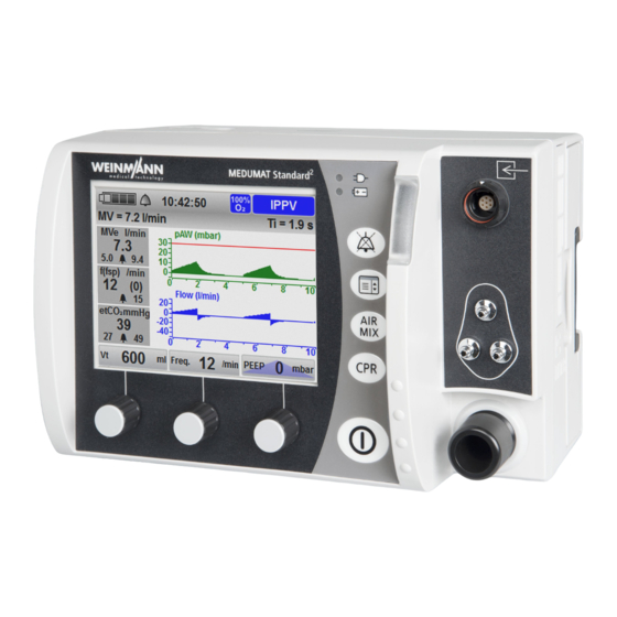
-
Contents
-
Table of Contents
-
Bookmarks
Quick Links
2
MEDUMAT Standard
Ventilator
Instructions for Use for Devices from Software Version 4.1
Related Manuals for Weinmann MEDUMAT Standard2
Summary of Contents for Weinmann MEDUMAT Standard2
-
Page 1
MEDUMAT Standard Ventilator Instructions for Use for Devices from Software Version 4.1… -
Page 2: Table Of Contents
Table of Contents Table of Contents Introduction Intended use …………….. 5 Operator and user qualification …………. 6 Contraindications …………….6 Side effects ………………. 6 Safety Safety information …………….. 7 General instructions …………..16 Warnings in this document …………17 Description Overview ………………
-
Page 3: Table Of Contents
Table of Contents 4.12 After use ………………94 4.13 Using the SD card ……………. 95 4.14 Enabling options …………….. 97 4.15 Updating the software …………… 100 4.16 Pairing an external data documentation system with ® MEDUMAT Standard for the first time (via Bluetooth ) ….
-
Page 4: Table Of Contents
Table of Contents Testing the reusable hose system ……….191 Checking the system for leaks ………… 192 Rectifying leaks in the system ………… 192 Alarms and error messages 10.1 General instructions …………..194 10.2 Alarm messages ……………. 196 10.3 Faults ………………201 Maintenance 11.1 General instructions …………..
-
Page 5: Intended Use
1 Introduction Introduction 1.1 Intended use MEDUMAT Standard is an automatic oxygen emergency ventilator with functions for the monitoring of respiratory values. MEDUMAT Standard is used in the treatment of infants, children and adults where spontaneous respiration has failed or is inadequate.
-
Page 6: Operator And User Qualification
(in Germany, particularly the German regulations governing owners/operators of medical devices (MPBetreibV)). General recommendation: You should seek instruction on the correct handling, use and operation of this medical device from a person authorized by WEINMANN Emergency. 1.3 Contraindications Possible contraindications for ventilation include: •…
-
Page 7: Safety Information
2 Safety Safety 2.1 Safety information Read these instructions for use carefully. They form part of the devices described, and must be available at all times. Use the device for the designated purpose only (see «1.1 Intended use», page 5). For your own safety as well as that of your patients, and in accordance with the requirements of Directive 93/42/EEC, please observe the following safety instructions.
-
Page 8
2 Safety Risk of injury due to device or component malfunction! A damaged device or damaged components may result in injury to the patient, user or bystanders. Only operate the device and components if they are externally undamaged. Only operate the device and components if the function check has been successfully completed. -
Page 9
Accessories which are connected to the device may cause an electrical potential in the device. This may lead to an electric shock on contact with the device and result in injury to the user. Only use accessories from WEINMANN Emergency. MEDUMAT Standard… -
Page 10: Power Supply
Risk of injury as a result of pressure variations during use in combination with devices from the WEINMANN Emergency MODUL range! If the device is used together with devices from the WEINMANN Emergency MODUL range, the flow used by devices from the WEINMANN Emergency MODUL series may cause pressure variations in the device.
-
Page 11
The use of a non-original power supply may result in injury to the user. Only operate the device on line power using the power supply recommended by WEINMANN Emergency. Caution Risk of injury from touching the contacts in the battery compartment and the patient at the same time! The contacts in the battery compartment are live. -
Page 12
2 Safety Caution Risk of injury from touching the contacts on the FlowCheck sensor connection line/FlowCheck sensor connection line with MEDUtrigger and the patient at the same time! The contacts on the FlowCheck sensor connection line/FlowCheck sensor connection line with MEDUtrigger are live. Touching the contacts and the patient at the same time can injure the user or the patient. -
Page 13
2 Safety Risk of injury due to airway pressures which are excessively high or too low! Airway pressures which are excessively high or too low may result in injury to the patient. Check correct ventilation on the display. Adjust the pressure limitation (pMax) to suit the connected patient. -
Page 14
2 Safety Risk of injury due to unsuitable concentrator gas! Unsuitable concentrator gas may distort treatment and result in injury to the patient. Only use concentrator oxygen (90% to 96% oxygen) or medical oxygen. Risk of injury if the patient valve is covered! The patient valve may be covered due to the position of the patient and prevented from functioning properly. -
Page 15
2 Safety Do not smoke. Do not use open flames. Ensure adequate ventilation. Keep the device and screwed unions free from oil and grease. Always close the SD card cover again following the insertion and removal of the SD card. Risk of injury if oxygen escapes from damaged oxygen cylinders or pressure reducers! Oxygen can escape unchecked from damaged oxygen cylinders or… -
Page 16: General Instructions
• Repairs, servicing and maintenance should only be carried out by the manufacturer, WEINMANN Emergency, or by a technician expressly authorized by WEINMANN Emergency. • Only have modifications to the device carried out by the manufacturer, WEINMANN Emergency, or by a technician expressly authorized by WEINMANN Emergency.
-
Page 17: Warnings In This Document
2 Safety • The software for the FlowCheck sensor connection line with MEDUtrigger/FlowCheck sensor connection line was created with FreeRTOS (www.freertos.org). 2.3 Warnings in this document Warnings are used to flag up safety-relevant information. You will find a warning preceding any action that entails a hazard for persons or equipment.
-
Page 18: Description
3 Description Description 3.1 Overview 3-1 Device Designation Description Displays settings and current values (see Display «3.4 Symbols on the display», page 26). Used for servicing purposes. May only be opened by Service cover the manufacturer or persons authorized by the manufacturer. Alarm light Indicates high-priority alarms visually.
-
Page 19
3 Description Designation Description Filter compartment Houses the hygiene filter/device input filter. Battery compartment with battery Houses the battery. Power connection Connects the device to the power supply. Used for connecting the oxygen supply (e.g., an Compressed gas connection oxygen cylinder). SD card slot For inserting an SD card. -
Page 20: Control Panel
3 Description 3.2 Control panel 3-2 Controls Designation Description • Steady green light: Indicates that the device is connected to line power. • No light: The device is operating on battery power Line power indicator and not on line power. The device is in NVG mode.
-
Page 21
3 Description Designation Description • Pressing the button briefly (< 1 s) mutes the alarm for 120 s. Alarm mute button • Keeping the button depressed (≥ 1 s) opens the alarm limit menu. • In the start menu: Provides access to the operator menu. -
Page 22: Display
3 Description 3.3 Display 3.3.1 Start menu 3-3 Start menu display Designation Description Battery status Displays the charge level of the battery. Indicates whether the audio alarm output is active or Alarm has been muted. Time Displays the current time. 100% O Indicates whether operation with 100% oxygen or Air Air Mix…
-
Page 23
3 Description 3.3.2 Ventilation mode (example) 3-4 Display in the views 1 (pressure, CO curve) (top left), 2 (pressure gauge, measurements) (top right), 3 (etCO trend) (center left), 4 (pressure, flow curve) (center right), 5 (CCSV mode) (bottom left), 6 (pressure curve, measurements) (bottom right) MEDUMAT Standard… -
Page 24
3 Description Designation Description • Indicates ventilation pressure progress. • Indicates pMax as a dotted line. • Indicates the currently attuning airway pressure as a green area. Pressure gauge • Indicates the maximum airway pressure in the middle. • Indicates the end-tidal CO concentration (etCO in the middle (only with capnography option). -
Page 25
3 Description Designation Description • Indicates the total respiratory rate. • Indicates the number of spontaneous breaths per Respiratory rate (f(fsp)) (only with flow measurement + ASB option) minute. • Indicates the associated upper alarm limit. • Displays whether manual or automatic chest compression is set. -
Page 26: Symbols On The Display
3 Description 3.4 Symbols on the display Symbol Designation Description Audio alarm output active Audio alarm output muted for 120 s (with Alarm symbol the exception of an alarm at a supply pressure < 2.7 bar) Acoustic alarm output permanently muted (NVG mode only) Battery status >…
-
Page 27
3 Description Symbol Designation Description Device ready for use Device not ready for use Function check symbol Fault found during function check Observe the instructions for use Repair necessary Metronome sound in CPR mode is switched on Metronome sound in CPR mode is switched off Period during which the device is in the CPR mode Ventilation mode symbols… -
Page 28: Components
3 Description Symbol Designation Description Manual chest compression Operation with manual chest compression Automatic chest Operation with chest compression device compression 3.5 Components 3.5.1 Overview 3-5 Components MEDUMAT Standard…
-
Page 29
3 Description Designation Description FlowCheck sensor connection line with Connects the MEDUtrigger and the FlowCheck sensor MEDUtrigger to the device. FlowCheck sensor connection line Connects the FlowCheck sensor to the device. Inhalation adapter Facilitates inhalation. Ventilation mask Connects the patient hose system to the patient. Protects the device from viral and bacterial Hygiene filter contamination. -
Page 30
3 Description 3.5.2 Reusable hose system and disposable hose system 17 16 3-6 Reusable hose system (top) and disposable hose system (bottom) Designation Description Service label (only with reusable hose Indicates the date when the next maintenance is due. system) Hose protection sleeve (only with Protects the ventilation hose against soiling reusable hose system) -
Page 31
3 Description Designation Description • Fixes the patient hose system to the patient’s clothing. Velcro strap with clip • Fixes the MEDUtrigger to the patient hose system when not in use (e.g., during CPAP applications). Protective cap (only with reusable hose Protects the end of the patient hose system closest to system) the patient from damage. -
Page 32
3 Description Designation Description The device measures the patient’s vital parameters via the measuring hose system. The measuring hose system comprises: • Measuring hose system connector Measuring hose system • PEEP control hose • Pressure-measurement hose • measuring hose (only with capnography option) The water filter protects the measuring chamber of the Water filter (only with capnography… -
Page 33
3 Description Designation Description Due to the check valve diaphragm, the respiratory gas Check valve diaphragm only flows towards the patient. No rebreathing takes place. Connects the patient valve to the ventilation hose and Holder for check valve diaphragm contains the check valve diaphragm. 3.5.4 Disposable hose system with reduced dead space 3-8 Disposable hose system with reduced dead space… -
Page 34
3 Description Designation Description Patient valve Switches between inspiration and expiration. Connects the MEDUtrigger and the FlowCheck sensor FlowCheck sensor connection line with to the device. Alternatively, you can also connect the MEDUtrigger (only with flow FlowCheck sensor connection line or the connection measurement + ASB option) line of the MEDUtrigger here. -
Page 35: Accessories
3 Description Designation Description The respiratory gas flows from the device to the Ventilation hose patient valve through the ventilation hose. 3.6 Accessories 3-9 Accessories Designation Description Charging station Facilitates external battery charging. Supplies power to the device from the vehicle’s 12 V cable electrical system.
-
Page 36: Options
Used for reading session data and log files and SD card updating the device software. Simulates a ventilated patient for presentation EasyLung for WEINMANN Emergency purposes and during a function check. Serves to ensure that the respiratory air is filtered and Breathing system filter conditioned.
-
Page 37: Labels And Symbols
3 Description 3.8 Labels and symbols 3.8.1 Labels on the product 3-10 Labels on the product Symbol Description Device information label Serial number Type BF applied part Input (12 V to 15 V) DC voltage MEDUMAT Standard…
-
Page 38
3 Description Symbol Description Device information label (continued) Type of protection against electric shock: Protection class II device Do not dispose of device in household waste Manufacturer Degree of protection against: • Ingress of solid objects IP54 • Ingress of dust •… -
Page 39
3 Description Symbol Description Input voltage (12 V-15 V) Input 13 / 14 Type BF applied part 3.8.2 Symbols on the battery 3-11 Symbols on the battery Symbol Description Battery fault, if fault indicator light is red Battery status 3 / 9 Observe the instructions for use. -
Page 40
3 Description Symbol Description Manufacturer Do not dispose of battery in household waste. China RoHS label (confirms that the product does not emit toxic substances for the number of years indicated) MEDUMAT Standard… -
Page 41
3 Description 3.8.3 Symbols on the patient hose system 3-12 Symbols on the patient hose system Symbol Description Reusable hose system and disposable hose system Indicates the correct flow direction during inspiration. Indicates the correct installation direction of the PEEP control diaphragm. CE mark (confirms that the product complies with the applicable European directives) MEDUMAT Standard… -
Page 42
3 Description Symbol Description Calendar clock for year and month Observe the instructions for use. >PC< Material designation: Polycarbonate 134°C Steam sterilization at 134°C Additional symbols, for reusable hose system only Indicates the date when the next maintenance is due (position: on the service label). -
Page 43
3 Description 3.8.5 Symbols on the hygiene filter/device input filter Symbol Description Disposable item, do not reuse Additionally hygiene filter only Manufacturer 3.8.6 Labels on the packaging Symbol Description Device Protect the device against moisture. Permissible storage temperature: -40°C to +70°C Permissible humidity for storage: max. -
Page 44
3 Description Symbol Description Permissible humidity for storage: Max. 95% relative humidity Serial number Manufacturer Patient hose system (reusable hose system and disposable hose system) Latex-free Latex Permissible storage temperature: -30°C to +70°C Permissible humidity for storage: 15% to 95% relative humidity CE mark (confirms that the product complies with the applicable European directives) Manufacturer Additional symbols, for disposable hose system only… -
Page 45
3 Description Disposable item, do not reuse Manufacturer Additionally hygiene filter only Permissible storage temperature: -30°C to +70°C Expiration date Additional symbols, for device input filter only Permissible storage temperature: -40°C to +70°C MEDUMAT Standard… -
Page 46: Preparation And Operation
4 Preparation and operation Preparation and operation 4.1 Mounting the device The device is mounted on a portable system as standard and is ready for use. Observe the instructions for use of the portable systems. 4.2 Connecting to a power supply Loss of power due to combination of the device with an incorrect power supply! If you use a portable system which combines the…
-
Page 47: Using The Rechargeable Battery
4 Preparation and operation 4. If necessary: If operating on the portable system, mount the portable system on a wall mounting with charging interface. Connect the device up to the line power with the charging adapter (WM 28979) and the 50 W or 100 W power supply Connect the device up to the vehicle’s electrical system with the charging adapter (WM 28979) and 12 V cable.
-
Page 48
4 Preparation and operation • external supply of at least 10 V is connected • battery is not yet fully charged (< 95% charge level) • battery temperature between 0°C and 45°C If the device is switched on, the green arrow appears in the battery status symbol on the display (example: ) and the battery status indicator on the device flashes green. -
Page 49
4 Preparation and operation Fault indicator Status LEDs Status 4-1 Status indicator on the battery Status indicator Explanation Meaning 4 LEDs are lit Battery status > 90% Battery status 3 LEDs are lit approx. 60%-90% Battery status 2 LEDs are lit approx. -
Page 50
4 Preparation and operation Device If the device is switched on, you can see the battery status on the display: Status indicator Meaning Battery status > 90% Battery status approx. 60%-90% Battery status approx. 40%-60% Battery status approx. 10%-40% Battery status < 10% •… -
Page 51: Changing The Battery
4 Preparation and operation 4.3.5 Changing the battery Requirement The replacement battery is fully charged. 1. Switch off the device (see «4.6 Switching the device off», page 66). Connect the device to the line power. 2. Take battery out of the battery compartment. 3.
-
Page 52
4 Preparation and operation 3. Perform a function check (see «9.3 Performing a function check», page 184). Result The hygiene filter has been inserted. 4.4.2 Inserting the device input filter 1. Check the device input filter for external damage. If necessary: Replace the device input filter. Device may be damaged if a device input filter which has already been pushed together is inserted in the filter compartment! -
Page 53
4 Preparation and operation 5. Perform a function check (see «9.3 Performing a function check», page 184). Result The device input filter has been inserted. 4.4.3 Connecting the patient hose system Risk of injury posed by ventilation with inhalation mask, tube, or nasal cannula! Ventilation with an inhalation mask, tube, or nasal cannula connected may cause an injury to the patient. -
Page 54
4 Preparation and operation 3. If necessary: Connect the FlowCheck sensor (see «4.4.4 Connecting the FlowCheck sensor», page 55). 4. If necessary: Connect MEDUtrigger (see «4.4.6 Connecting MEDUtrigger», page 59). 5. If necessary: Connect the CO measuring hose (see «4.4.5 Connecting the CO measuring hose», page 57). -
Page 55
4 Preparation and operation 7. If necessary: Attach the patient hose system with Velcro strap with clip to the patient’s clothing. Result The patient hose system is connected and ready for use. 4.4.4 Connecting the FlowCheck sensor The FlowCheck sensor enables flow measurement (only with flow measurement + ASB option). -
Page 56
4 Preparation and operation 2. Connect the FlowCheck sensor to the patient valve. Risk of injury from touching the contacts on the FlowCheck sensor connection line/FlowCheck sensor connection line with MEDUtrigger and the patient at the same time! The contacts on the FlowCheck sensor connection line/FlowCheck sensor connection line with MEDUtrigger are live. -
Page 57
4 Preparation and operation 4. With the reusable hose system: Guide the connection line with measuring hose system and ventilation hose into the hose protection sleeve of the patient hose system. 5. If necessary: Activate flow measurement + ASB option (see «6.3.9 Options», page 134). -
Page 58
4 Preparation and operation 1. Connect the water filter to the CO measuring hose. 2. Connect the CO measuring hose with water filter to the measuring hose system connector. 3. With the reusable hose system: Connect the connector with Luer lock connector: •… -
Page 59
4 Preparation and operation 5. With disposable hose systems: Connect the CO measuring hose to the elbow with Luer lock connector. To minimize the dead space, you can also connect the CO measuring hose to a breathing system filter with Luer lock connector (e.g., WM 22162). -
Page 60
4 Preparation and operation MEDUtrigger button LEDs 4-2 Connection line of MEDUtrigger (1) and FlowCheck sensor connection line with MEDUtrigger (2) 1. Connect the connector of one of the following connection lines to the accessory connection on the device: • Connection line of MEDUtrigger •… -
Page 61
4 Preparation and operation 3. Place MEDUtrigger between the mask and the following end of the patient hose system closest to the patient: • Patient valve • FlowCheck sensor • Connector with Luer lock connector • Elbow If you use a breathing system filter, always place MEDUtrigger between the mask and the breathing system filter. -
Page 62
4 Preparation and operation 4. With the reusable hose system: Guide the connection line with measuring hose system and ventilation hose into the hose protection sleeve of the patient hose system. 5. If necessary: Activate MEDUtrigger option (see «6.3.9 Options», page 134). Result The MEDUtrigger is connected to the device and is ready for use. -
Page 63
4 Preparation and operation 3. Perform inhalation (see «4.7.7 Performing inhalation (only with Inhalation option)», page 76). Result Inhalation via the inhalation adapter is prepared. 4.4.8 Connecting the etCO nasal cannula 1. Position the etCO nasal cannula. 2. If necessary: Fix the tubes of the etCO nasal cannula to the face using adhesive plasters. -
Page 64
4 Preparation and operation 4.4.9 Connect up the nebulizer Only use the device in combination with the following nebulizer: • Pneumatic drug nebulizer WM 15827 1 • Aerogen Solo (Inspiration Medical GmbH) 2 • Tube Inhaler (VBM Medizintechnik GmbH) 3 Risk of injury due to erroneous readings! If the filter is installed incorrectly or no filter is used, the membrane may stick in the patient valve or the FlowCheck sensor could… -
Page 65: Switching The Device On
4 Preparation and operation 2. Connect the open end of the nebulizer 1, 2, or 3 with the filter 7 (breathing system filter, bacteria filter, or a combined breathing system/bacteria filter). 3. Place the filter 7 (breathing system filter, bacteria filter, or a combined breathing system/bacteria filter) on the patient hose system’s FlowCheck sensor 8.
-
Page 66: Switching The Device Off
4 Preparation and operation If you switch the device on in NVG mode, the following displays are deactivated: • Alarm light • Line power indicator • Battery status indicator • Audio alarm output The start screen with the selected NVG brightness appears (see «6.3.7 Device configuration», page 125).
-
Page 67: Ventilating The Patient
4 Preparation and operation 4.7 Ventilating the patient 4.7.1 Selecting the emergency mode from the start menu Requirement The device is switched off. 1. Switch on the device. After the self-test, the device displays the start menu: If the device was switched off for < 30 seconds (e.g., for a battery change), a countdown in the Previous patient field counts down 20 seconds.
-
Page 68
4 Preparation and operation Depending on the preset in the operator menu, the device switches to one of the following modes with the ventilation parameters preset for the patient group (see «14.1.9 Factory settings for emergency modes and ventilation modes», page 234) and shows a pressure gauge view: •… -
Page 69
4 Preparation and operation 2. Select Previous patient field. Allow the countdown to run. 3. If necessary: Adjust the settings of the last patient and confirm. Result The ventilation mode, ventilation parameters and the view of the last ventilated patient are loaded. MEDUMAT Standard… -
Page 70
4 Preparation and operation 4.7.3 Selecting a ventilation mode for a new patient Requirement The device is switched off. 1. Switch on the device. After the self-test, the device displays the start menu: If the device was switched off for < 30 seconds (e.g., for a battery change), a countdown in the Previous patient field counts down 20 seconds. -
Page 71
4 Preparation and operation 3. Select the height and gender: The height is given in 5 cm increments between 50 cm and 250 cm. (see «14.2 Calculation of body weight on the basis of body height», page 234). Navigate to the field Height and turn the navigation knob further to select the desired patient group: MEDUMAT Standard… -
Page 72
4 Preparation and operation • Adult • Child • Infant 4. Press the navigation knob next. 5. Select a ventilation mode. 6. If necessary: Set the parameters of the ventilation mode. MEDUMAT Standard… -
Page 73
4 Preparation and operation 7. Select the start field. Result A ventilation mode for a new patient has been set. If the curve display option is activated, the device shows a curve view. 4.7.4 Selecting an emergency mode from a ventilation mode Requirement •… -
Page 74
4 Preparation and operation • IPPV • BiLevel + ASB (only if the BiLevel + ASB option is activated) You can adjust the preset ventilation parameters for the emergency modes in the operator menu: Operator menu | Presets patient. Result An emergency mode for a particular patient group is activated. -
Page 75
4 Preparation and operation 4. If necessary: Set the parameters of the ventilation mode. 5. Select the start field. Result The ventilation mode is changed. 4.7.6 Operating the device in oxygen or Air Mix mode Requirement • The device is switched on. •… -
Page 76
4 Preparation and operation Oxygen mode is activated as standard for all emergency modes. Result The device is operated in oxygen or Air Mix mode. 4.7.7 Performing inhalation (only with Inhalation option) Using a nebulizer prevents treatment in Inhalation mode! The device is not suitable for nebulizers in inhalation mode. -
Page 77
4 Preparation and operation 3. Select the field Inhalation using the left-hand navigation knob. The device switches to Inhalation mode. 4. Select flow for inhalation using the right-hand navigation knob. Result The inhalation is performed. 4.7.8 Performing CO monitoring (only with capnography option) Requirement •… -
Page 78
4 Preparation and operation 1. Assess CO measurements diagnostically. Result The CO measurements and the respiratory rate of the patient are monitored. 4.7.9 Performing ventilation in CPR Manual mode In CPR Manual mode, you determine the respiratory rate administered yourself. Using MEDUtrigger, you manually trigger individual mechanical breaths with the set tidal volume. -
Page 79
4 Preparation and operation • Manual was set in the operator menu (Operator menu | Presets patient | CPR mode | Start mode). 1. Briefly press the CPR button The device switches to the mode CPR Man. The green LEDs on the MEDUtrigger light up. -
Page 80
4 Preparation and operation The device always switches to IPPV mode upon exiting CPR mode. Result Ventilation is performed in CPR Manual mode. 4.7.10 Performing ventilation in CPR IPPV mode Delay in treatment due to simultaneous metronome outputs from the ventilator and the defibrillator! If the ventilator is used together with a defibrillator (MEDUCORE Standard) which can also emit a metronome sound, the simultaneous metronome outputs from the defibrillator and the… -
Page 81
4 Preparation and operation Pausing ventilation in CPR IPPV mode During the analysis of the defibrillator, you can pause ventilation in order to avoid artifacts in the analysis. Requirement • The device is switched on. • The CPR mode is set. •… -
Page 82
4 Preparation and operation 3. To start continuous ventilation again: Press the field twice. Result Ventilation pauses. When the countdown reaches zero, ventilation automatically restarts. 4.7.11 Performing ventilation in CPR CCSV mode Delay in treatment due to simultaneous metronome outputs from the ventilator and the defibrillator! If the ventilator is used together with a defibrillator, which can also emit a metronome sound, the simultaneous metronome outputs… -
Page 83
4 Preparation and operation Requirement • The device is switched on. • The CCSV option is activated. 1. Briefly press the CPR button Depending on the preset in the operator menu, the device switches to CPR CCSV mode or CPR Manual mode (Operator menu | Presets patient | CPR mode | Start mode). -
Page 84
4 Preparation and operation 4.7.12 Replacing CPR mode Requirement • The device is switched on. • The CCSV option is activated. • The CPR mode is set. • Continuous ventilation is activated. 1. To change the mode, switch between the CCSV and IPPV fields using the right navigation knob. -
Page 85
4 Preparation and operation 1. For the function Manual, navigate to the field Demand and select the field Manual. To enable the selection of the Manual function, a MEDUtrigger must be connected and activated in the operator menu. Otherwise, this function will not be displayed. MEDUMAT Standard… -
Page 86
4 Preparation and operation 2. To perform continuous ventilation following successful airway management, select the Contin. field. Depending on the preset in the operator menu, the device switches to one of the following modes with the ventilation parameters preset for the patient group (see «14.1.9 Factory settings for emergency modes and ventilation modes», page 234):… -
Page 87
4 Preparation and operation 1. Switch on the device and during start-up press the right-hand and left-hand navigation knobs at the same time. The device switches to simulation mode. The words Simulation Mode! flash in the display. 2. Simulate settings. 3. -
Page 88: Monitoring The Patient
4 Preparation and operation 4.8 Monitoring the patient During ventilation, you must monitor the patient continuously. You can see the ventilation progress on the gauge, on the ventilation curves and on the measurements shown on the display of the device (see «3.3.2 Ventilation mode (example)», page 23).
-
Page 89: Audio Alarm Output
4 Preparation and operation 4.9 Audio alarm output 4.9.1 Muting the audio alarm output Requirement An alarm is active and is audible. 1. Briefly (< 1 s) press the alarm mute button The acoustic alarm output is permanently muted in NVG mode. Result The audio alarm output is muted for 120 s.
-
Page 90: Transporting The Device
4 Preparation and operation 4.10 Transporting the device 4-4 Transport on a portable system You can transport the device in the following ways: • On the portable system LIFE-BASE 3 NG (1) • On the portable system LIFE-BASE 1 NG XS (2) •…
-
Page 91: Feeding In Oxygen
4 Preparation and operation 4.11 Feeding in oxygen 4.11.1 Connecting an oxygen supply Risk of injury posed by the combination of highly compressed oxygen and hydrocarbon compounds! When combined with highly compressed oxygen, hydrocarbon compounds (e.g., oil, grease, cleaning alcohols, hand cream or adhesive plasters) can cause explosions and injuries to the patient, user and bystanders.
-
Page 92
4 Preparation and operation Requirement • The patient is not connected to the device. • The oxygen cylinder is full. 1. Briefly open and then close the valve of the oxygen cylinder in order to blow away any particles of dust. 2. -
Page 93
4 Preparation and operation 4.11.2 Removing the oxygen supply 1. Close the valve on the oxygen cylinder. 2. Briefly press the On/Off button and operate the device without an oxygen supply. The remaining oxygen is flushed out of the device. 3. -
Page 94: After Use
4 Preparation and operation Air Mix mode: Oxygen supply l ( ) 2 × ——————————————————— — Time min 1 – Vt l ( ) f min × 0.3l Example Oxygen supply 2000 l 500 ml 12 min Time 634 min = 10 h 34 min Result The operating time has been calculated.
-
Page 95: Using The Sd Card
4.13 Using the SD card 4.13.1 Inserting an SD card Loss of data due to incorrect SD card! SD cards not purchased from WEINMANN Emergency may have reduced functionality or result in the loss of data. Only use SD cards from WEINMANN Emergency.
-
Page 96
4 Preparation and operation 4.13.2 Removing the SD card Requirement An SD card is in the SD card slot. 1. Open the splash guard of the SD card slot. Incorrect use may result in loss of data or damage to the device! If you remove the SD card whilst exporting log files or updating the software of the device, data may be lost or the device may be… -
Page 97: Enabling Options
4 Preparation and operation 4.14 Enabling options Requirement • The operator menu has been called up (see «6.1 Navigating the operator menu», page 116). • The latest software version is installed on the device (see «4.15 Updating the software», page 100). 1. Select the menu item Options. 2.
-
Page 98
4 Preparation and operation 3. Turn the right-hand navigation knob to enter the first digit of the option code. 4. Press the navigation knob next to confirm the first digit of the option code. 5. Enter the other digits of the option code in the same way. 6. -
Page 99
4 Preparation and operation The device uses a green checkmark to display whether the input option code is correct and changes the color of the option as per the color scale above. When doing so, note: Prerequisite for the unlocking of the curve display option: Flow measurement + ASB option is enabled. -
Page 100: Updating The Software
1. If necessary: Download the software from the Login area of the WEINMANN Emergency website to the SD card. 2. If the software is available as a ZIP file: Unzip the software. The software is available in the folder as a file named WM28981-x.x.hex.
-
Page 101
4 Preparation and operation 5. Select Software update. Damage to the device caused by moving the device and/or pressing buttons during the update! Moving the device and/or pressing buttons during the update may cancel the update and damage the device. … -
Page 102
4 Preparation and operation The update.txt file is saved to the SD card in the device as soon as the software update is complete. The file contains information on the software update just performed. This helps you with documentation within the scope of your quality management process. -
Page 103
4 Preparation and operation 4. If necessary: Enter the device’s Bluetooth PIN in the external data documentation system. Result The device is paired with the external data documentation system ® via Bluetooth 4.16.2 Pairing during ventilation Requirement • The external data documentation system supports the device’s communication protocol. -
Page 104: User Menu
5 User menu User menu 5.1 Navigating the user menu Requirement A ventilation mode is set. 1. Briefly press the menu button 2. To select a submenu, turn one of the three navigation knobs. 3. To confirm the settings, press one of the three navigation knobs.
-
Page 105: Structure Of The User Menu
5 User menu 5.2 Structure of the user menu Mode IPPV BiLevel + ASB CPAP CPAP + ASB aPCV PRVC + ASB SIMV SIMV + ASB RSI DEMAND S-IPPV RSI Man. RSI IPPV CPR Man. Demand CPR IPPV CPR IPPV Inhalation CPR CCSV monitoring…
-
Page 106: Settings In The User Menu
5 User menu 5.3 Settings in the user menu 5.3.1 Mode 5-2 Mode submenu You can select the following ventilation modes and additional functions here (see «7 Description of the modes», page 136): MEDUMAT Standard…
-
Page 107
5 User menu Mode submenu IPPV BiLevel + ASB (only if the pressure- controlled ventilation modes option is activated) CPAP CPAP + ASB (only with flow measurement + ASB option) aPCV (only if the pressure-controlled ventilation modes option is activated) Ventilation modes PCV (only if the pressure-controlled ventilation modes option is activated) -
Page 108: Alarm Limits
5 User menu 5.3.2 Alarm limits 5-3 Alarm limits submenu Here you can set the alarm limits. You can also open the alarm limit menu by keeping the alarm mute button depressed. Risk of injury due to alarm limits which are too high or too low! Alarm limits which are either too high or too low can prevent the device from emitting an alarm, thereby putting the patient at risk.
-
Page 109
5 User menu Alarm Setting range Activating automatic limits The device sets the alarm limits for the alarms relating to respiratory physiology automatically. The deviation is 10%, 20% or 30% from Automatic limits the ventilation values at the time of activation. -
Page 110
5 User menu 5.3.3 Views 5-4 Views submenu (example) You can select preconfigured views of measurements here. The views depend on the activated options and the ventilation mode selected. MEDUMAT Standard… -
Page 111
5 User menu 5.3.4 Ventilation parameters 5-5 Ventilation parameters submenu (example) You can change the ventilation parameters of the selected ventilation mode here. 5.3.5 Apnea ventilation 5-6 Apnea ventilation submenu MEDUMAT Standard… -
Page 112
5 User menu In this menu you can activate or deactivate apnea ventilation in the CPAP, CPAP + ASB and Demand ventilation modes. When apnea ventilation is activated, the device automatically switches to IPPV mode once the set apnea time has elapsed. If the BiLevel + ASB mode is unlocked in the operator menu and activated, you can choose between the IPPV mode and the BiLevel + ASB mode as the apnea ventilation mode in the operator… -
Page 113
5 User menu In this menu you can set the scale for the time axis of the etCO trend. The following settings are possible: auto, 5 min., 10 min., 30 min., 60 min.,120 min. At a time setting of 5 minutes or 10 minutes, the device records the determined value every 15 seconds. -
Page 114
5 User menu 5.3.8 NVG (Night Vision Goggles) 5-9 NVG submenu Risk of injury from deactivated alarm light, deactivated audio alarm output and darkened display in NVG mode! The alarms are barely perceptible as a result of the deactivated alarm light, the deactivated audio alarm output and the darkened display in NVG mode. -
Page 115
5 User menu A device in NVG mode does not comply with the following standards with respect to alarm output: • EN 60601-1-8 • EN 794-3/EN 10651-3. The operator assumes the resulting risk for operation. MEDUMAT Standard… -
Page 116: Operator Menu
6 Operator menu Operator menu 6.1 Navigating the operator menu 1. Switch on the device. The start menu appears. 2. Briefly press the menu button 3. Turn the right-hand navigation knob to enter the first digit of the access code. 4.
-
Page 117
6 Operator menu 7. To select a submenu, turn one of the three navigation knobs. 8. To call up a submenu, press one of the three navigation knobs. 9. To select a desired value, turn one of the three navigation knobs. -
Page 118: Structure Of The Operator Menu
6 Operator menu 6.2 Structure of the operator menu Device information Battery information Export log files FlowCheck information Export session data Export configuration Export configuration Import / Export Import configuration Date / Time Software update Volume Change access code Brightness NVG brightness Device configuration Allow bluetooth pairing…
-
Page 119: Settings In The Operator Menu
6 Operator menu 6.3 Settings in the operator menu 6.3.1 Device information 6-2 Device information submenu You will find all the information on the device in this submenu. 6.3.2 Battery information 6-3 Battery information submenu You will find all the information on the battery in this submenu. MEDUMAT Standard…
-
Page 120
6 Operator menu 6.3.3 FlowCheck information (only with flow measurement + ASB option) 6-4 FlowCheck information submenu You will find all the information on the FlowCheck sensor and the following connection lines in this submenu: • FlowCheck sensor connection line •… -
Page 121
6 Operator menu 6.3.4 Import / Export 6-5 Import / Export submenu Export log files The device always saves the log files in its internal memory. You can export data to an SD card in order to analyze it. Detailed information on exported log files can be found in the appendix (see «14.3 Exported log files», page 235). -
Page 122
6 Operator menu Export configuration The Export configuration function allows you to export all the configuration settings made on the device to an SD card. When exporting, all the configuration settings (including the options) are transferred with the exception of the following configuration settings: •… -
Page 123
6 Operator menu Exporting data to an SD card Requirement • An SD card is in the SD card slot. • The operator menu has been called up (see «6.1 Navigating the operator menu», page 116). 1. Select the menu item Import / Export. 2. -
Page 124
6 Operator menu 6.3.5 Software update 6-6 Software update submenu You can update your software here (see «4.15 Updating the software», page 100). 6.3.6 Change access code 6-7 Submenu for changing the access code Here you can change the access code for the operator menu. On delivery, the access code for the operator menu is 0000. -
Page 125
6 Operator menu 6.3.7 Device configuration 6-8 Device configuration submenu In the submenu Device configuration, you can set the following parameters for the device: Parameter Possible values Description Year Month Date / Time Here you can set the current date and time. Hour Minute Here you can set the volume of the acoustic… -
Page 126
6 Operator menu Parameter Possible values Description 0.1% to 3% in 0.1% increments 3% to 5% in 0.5% You can set the brightness here to which the NVG brightness (only with NVG increments device switches when the NVG mode is option) 5% to 10% in 1% activated. -
Page 127
6 Operator menu Parameter Possible values Description vol% unit (only with capnography Here you can select which unit of measurement option) the CO values should be displayed in. mmHG 93% O Supply gas Here you can set the type of supply gas. 100% O Here you can set the inspiration and expiration trigger:… -
Page 128
6 Operator menu 6.3.8 Presets patient 6-9 Presets patient submenu In the Presets patient submenu, you can determine which presets are assigned to the ventilation parameters of the different patient groups: Risk of injury from different alarm presets in the same or similar devices! Different alarm presets in the same or similar devices in different application areas can confuse the user and result in injury to the… -
Page 129
6 Operator menu Parameter Possible values Description Infant/Child/Adult Emergency mode (only if Here you can choose between IPPV the pressure-controlled IPPV mode or BiLevel + ASB as the ventilation modes BiLevel + ASB emergency ventilation mode per option is activated) patient group. -
Page 130
6 Operator menu Parameter Possible values Description Pressure gauge View (only with Here you can choose between a Pressure/CO curve activated pressure gauge view and a curve Pressure/etCO capnography option) view for the CPR mode. trend Here you can determine whether or ☑… -
Page 131
6 Operator menu Parameter Possible values Description Here you can set the ventilation pInsp 40 mbar — 60 mbar pressure. Here you can set the trigger for the Trigger 1 — 3 CCSV mode. Here you can set when the hands-off Hands-off time 10 s — 55 s time alarm… -
Page 132
6 Operator menu Parameter Possible values Description Here you can determine whether an etCO (only ☑ alarm should be output in the event with capnography ☐ of rising or dropping end-expiratory option) Apnea mode (only if the uncontrolled ventilation modes option is activated) Here you can set the apnea IPPV ventilation mode for the CPAP and… -
Page 133
6 Operator menu Setting height* Depending on the height selected (tidal volume Vt in ml per kg bodyweight) the height which can be set is restricted to the following minimum values: Tidal volume Vt in ml per kg Minimum height which can be bodyweight set in cm For the smallest height which can be set, the tidal volume is always… -
Page 134
6 Operator menu 6.3.9 Options 6-10 Options submenu As the operator, you can unlock new options for the user in the menu item Unlock option (see «4.14 Enabling options», page 97) and activate or deactivate the unlocked options. Options Description Enables connection of the MEDUtrigger MEDUtrigger to the device and use of the MEDUtrigger in CPR mode. -
Page 135
6 Operator menu Options Description Enables the PRVC + ASB pressure- PRVC + ASB controlled ventilation mode. Enables CO measurement and display of the CO curve. For CO Capnography measurement you require a device with CO measuring. Enables flow measurement with the FlowCheck sensor and the following ventilation modes: Flow measurement… -
Page 136: Description Of The Modes
7 Description of the modes Description of the modes 7.1 Classification of the ventilation modes Breathing effort 100% Patient Ventilator Assisted ventilation Controlled ventilation Spontaneous respiration The following ventilation modes are possible with this device: Control Controlled Assisted Spontaneous parameter ventilation ventilation respiration…
-
Page 137
7 Description of the modes There are the following trigger options in the individual ventilation modes: Trigger time Ventilation Expiration slot for Inspiration trigger ASB breath mode trigger mandatory breaths IPPV BiLevel + ASB 20% of Te CPAP CPAP + ASB Can be set from 0% aPCV — 100% of Te… -
Page 138: Ventilation Parameters
7 Description of the modes 7.2 Ventilation parameters Ventilation Unit Description parameters Tidal volume (breath volume) Freq. 1/min Ventilation rate pMax mbar Maximum inspiratory pressure PEEP mbar Positive end-expiratory pressure (CPAP) Ventilation through the addition of Air Mix ambient air 93% oxygen Ventilation with concentrator oxygen 100% oxygen…
-
Page 139
7 Description of the modes • If the flow measurement + ASB option is not activated: With a set PEEP value > 0 mbar, the patient must create an underpressure of at least -1.3 mbar below the set PEEP value through his/her spontaneous respiratory effort in order to initiate an inspiratory trigger in the device. -
Page 140: Ventilation Modes
7 Description of the modes 7.3 Ventilation modes 7.3.1 IPPV mode Description Abbreviation IPPV Intermittent Positive Pressure Long form Ventilation Type Volume-controlled Requirement None Ventilation parameters Left-hand navigation knob Central navigation knob Freq. • PEEP • pMax Right-hand navigation knob •…
-
Page 141
7 Description of the modes 7.3.2 BiLevel + ASB mode Description Abbreviation BiLevel + ASB Ventilation at two pressure Long form levels + Assisted Spontaneous Breathing Type Pressure-controlled • Flow measurement + ASB option is activated Requirement • Pressure-controlled ventilation modes option is activated •… -
Page 142
7 Description of the modes The BiLevel + ASB mode is used for pressure-controlled ventilation combined with free spontaneous respiration at pressure levels pInsp and PEEP during the entire breathing cycle and for adjustable pressure support at PEEP level. This mode is used on patients who have no spontaneous respiration or on spontaneously breathing patients. -
Page 143
7 Description of the modes CPAP Pressure pMax CPAP CPAP / PEEP Time 1/Freq. (spontaneous) 1/Freq. (spontaneous) The set value CPAP/PEEP is used to increase the pressure level of respiration in order to raise the functional residual capacity (FRC) of a spontaneously breathing patient. The patient is able to breathe spontaneously without any restriction at the set pressure level. -
Page 144
7 Description of the modes Ventilation parameters Left-hand navigation knob InTr Central navigation knob Δ pASB • PEEP • pMax Right-hand navigation knob • ExTr • Emergency mode CPAP + ASB Pressure pMax CPAP without pressure support CPAP with pressure support ASB ΔpASB CPAP / PEEP Time… -
Page 145
7 Description of the modes In principle, the pressure is set at the end of expiration (PEEP). If Δ necessary, the pressure support ( pASB) can be switched on. Ventilation can be individually adjusted to suit the patient with the aid of the inspiratory and expiratory triggers. -
Page 146
7 Description of the modes Ventilation parameters Left-hand navigation knob pInsp Central navigation knob Freq. PEEP pMax Right-hand navigation knob InTr Emergency mode aPCV Pressure pMax Synchronized Mechanical Mechanical mechanical ventilation ventilation ventilation pInsp Pressure ramp PEEP Time 1/Freq. (current) ∆T 1/Freq. -
Page 147
7 Description of the modes 7.3.6 PCV mode Description Abbreviation Long form Pressure Controlled Ventilation Type Pressure-controlled • Flow measurement + ASB option is activated Requirement • Pressure-controlled ventilation modes option is activated • Curve display option is activated Ventilation parameters Left-hand navigation knob pInsp Central navigation knob… -
Page 148
7 Description of the modes The PCV mode is used for mandatory pressure-controlled ventilation with fixed pressure levels. This mode is used on patients who have no spontaneous respiration. However, a spontaneously breathing patient can breathe deeply and freely during expiration. The set maximum pressure limitation (pMax) ensures the safety of the patient. -
Page 149
7 Description of the modes PRVC + ASB Pressure pMax Safety pPlateau distance 5 mbar pInsp (variable) Increment max. 3 mbar ∆pASB PEEP Time pressure-controlled volume-controlled pressure-controlled mechanical breath mechanical breath mechanical breath 1/Freq. (set) 1/Freq. (set) The controlled PRVC + ASB mode combines the advantages of both pressure-controlled ventilation and volume-controlled ventilation. -
Page 150
7 Description of the modes Once the maximum ventilation pressure (pMax-5 mbar) is achieved, the device administers as much volume as possible. If this volume deviates from the set tidal volume, the device triggers the medium-priority alarm «Vt not achievable». 7.3.8 SIMV mode Description Abbreviation… -
Page 151
7 Description of the modes The SIMV mode is used for volume-controlled ventilation with a fixed mandatory minute volume. The patient can breathe spontaneously between the mandatory mechanical breaths and thereby increase the minute volume. During spontaneous respiration, the mandatory mechanical breath is synchronized with the patient’s breathing. -
Page 152
7 Description of the modes SIMV + ASB Pressure p Max Mechanical ventilation Assisted Synchronized mechanical spontaneous ventilation breathing Spontaneous pPlat respiration ΔpASB PEEP Time ΔT 1/Freq. (current) 1/Freq. (set) Trigger time slot The SIMV + ASB mode is used for volume-controlled ventilation with a fixed mandatory minute volume. -
Page 153
7 Description of the modes 7.3.10 S-IPPV mode Risk of hyperventilation! When using the S-IPPV mode, the CO concentration in the patient’s blood can drop and injure the patient. Monitor the patient continuously. Risk of air trapping! When using the S-IPPV mode, air can become trapped in the patient’s lung. -
Page 154
7 Description of the modes S-IPPV Pressure Synchronized mechanical Mechanical ventilation ventilation pMax Plateau PEEP Time ΔT 1/Freq. (current) 1/Freq. (set) Trigger time slot The S-IPPV mode is used for volume-controlled ventilation with a variable mandatory minute volume. Throughout the entire expiration phase, a trigger is active which enables the patient to trigger a new breath. -
Page 155
7 Description of the modes 7.3.11 CCSV mode Risk of injury due to unsecured airway! If the CCSV mode is used, an unsecured airway can result in insufflation of the stomach and cause injury to the patient. Secure the airway. Description Abbreviation CCSV… -
Page 156: Additional Functions
7 Description of the modes The CCSV mode is a pressure-controlled ventilation mode employed specially and exclusively for resuscitation ventilation during continuing chest compression. The ventilation mode offers you support during cardiopulmonary resuscitation (in accordance with the resuscitation guidelines) by applying a defined pressure into the lungs in time with every chest compression and switches to expiration during the chest decompression phase.
-
Page 157
7 Description of the modes Ventilation parameters Left-hand navigation knob Vt pInsp • Central navigation knob Freq. • • Manual/ • Manual/ • Manual/ • pMax • CCSV/ • CCSV/IPPV IPPV • Trigger Right-hand navigation knob • Interval • pMax •… -
Page 158
7 Description of the modes If you do not perform chest compressions for an extended period of time in CPR CCSV mode, the device returns to IPPV back-up ventilation after the time preset in the operator menu. As soon as you recommence chest compressions, the device automatically returns to CSSV ventilation. -
Page 159
7 Description of the modes Following the selection of the RSI mode, the device launches the oxygen demand function immediately for the preoxygenation of a spontaneously breathing patient. For intubation, switch to the Manual function. The I:E ratio is always 1:1. With the MEDUtrigger supplied, this function now enables manual ventilation with a defined volume and a defined pressure limitation. -
Page 160
7 Description of the modes The Demand mode serves to (pre)oxygenate spontaneously breathing patients via a ventilation mask. The patient must trigger inspiration himself in Demand mode. If there is a FlowCheck sensor this recognizes the respiratory effort, otherwise the underpressure created is used. -
Page 161
7 Description of the modes Ventilation parameters • Left-hand navigation knob • pInsp Central navigation knob Freq • PEEP • pMax • Δ pASB (in BiLevel + ASB mode Right-hand navigation knob only) • InTr (in BiLevel + ASB mode only) •… -
Page 162
7 Description of the modes During apnea ventilation, the device emits a medium-priority alarm and the ventilation mode display turns red. The apnea ventilation mode can only be exited if the ventilation mode is changed actively. 7.4.5 Inhalation mode Description Abbreviation Long form Inhalation… -
Page 163
7 Description of the modes monitoring is used for the sidestream CO measurement during oxygen inhalation or bag-valve-mask ventilation (see «4.7.8 Performing CO monitoring (only with capnography option)», page 77). To use the CO measurement during oxygen inhalation, you require an interface with a male Luer lock connector for CO measurement (see «4.4.8 Connecting the… -
Page 164: Hygienic Reprocessing
• You can find further information about hygienic reprocessing and a list of all the suitable cleaning agents and disinfectants in a brochure on the Internet at www.weinmann-emergency.com. • The service life of the components of the reusable hose system is at least 30 reprocessing cycles (exception FlowCheck sensor: typically 50 reprocessing cycles).
-
Page 165: Intervals
8 Hygienic reprocessing 8.2 Intervals Clean the device, components and accessories after every use (but at least once a week). 8.3 Hygienic reprocessing of the device Risk of injury due to reuse of disposable items! Disposable items are intended for single use. Disposable items which are reused may be contaminated and/or impaired in their function and therefore cause injury to the patient.
-
Page 166
8 Hygienic reprocessing 8. Carry out hygienic reprocessing of the device, components and accessories as specified in the following table: Thermal Part Cleaning Disinfection Sterilization disinfection Device Battery Not permitted Power supply Steam sterilize at Wipe down with a 134°C (for a Wipe disinfection dry or moist cloth: minimum of… -
Page 167
8 Hygienic reprocessing Brush the parts thoroughly inside and outside using a normal laboratory soft bottle brush. Wet all surfaces, free of bubbles, inside and outside. Allow the full exposure time to elapse. Following disinfection, rinse the parts off and out thoroughly with distilled water and allow them to dry. The applicable instructions are those in the instructions for use from the manufacturers of the individual components or accessories. -
Page 168: Hygienic Reprocessing Of The Reusable Hose System
8 Hygienic reprocessing 8.4 Hygienic reprocessing of the reusable hose system Requirement The reusable hose system has been disassembled (see «8.6.1 Disassembly of the reusable hose system», page 172). 1. Carry out hygienic reprocessing of the reusable hose system as specified in the following table: Thermal Part Cleaning…
-
Page 169
8 Hygienic reprocessing Thermal Part Cleaning Disinfection Sterilization disinfection Rinse at up to Steam sterilize at 95°C 134°C (for a (Recommenda- minimum of Use the immersion Clean in warm tion: 5 mins and Connector with Luer lock disinfection method ® water with a mild thermosept maximum of… -
Page 170: Hygienic Reprocessing Of The Disposable Hose System
8 Hygienic reprocessing Only brush the outside of the part thoroughly using a normal laboratory soft bottle brush. Do not use a bottle brush on the inside in order to prevent damaging the sieves. Rinse thoroughly with distilled water after cleaning. Washing method according to the Robert Koch Institute (RKI) and the Association for Applied Hygiene (VAH) at 70°C with Derval SOLO (RKI) and with Ottalin PERACET)
-
Page 171
8 Hygienic reprocessing Thermal Part Cleaning Disinfection Sterilization disinfection Disposable hose system: • Ventilation hose • Patient valve • Elbow Disposable measuring hose system: • Measuring hose system connector • PEEP control hose • Pressure- Disposable item, do not reuse measurement hose •… -
Page 172
8 Hygienic reprocessing 8.6 Disassembly/assembly of the reusable hose system The images in this subchapter show all the possible components of the reusable hose system. Depending on the system type, your reusable hose system may not include certain components (see «3.5.2 Reusable hose system and disposable hose system», page 30). -
Page 173
8 Hygienic reprocessing 5. If available: Detach one of the following connection lines from the FlowCheck sensor: • FlowCheck sensor connection line • FlowCheck sensor connection line with MEDUtrigger 6. If available: Detach the CO measuring hose from the connector with Luer lock connector. MEDUMAT Standard… -
Page 174
8 Hygienic reprocessing 7. Detach the pressure-measurement hose (2) and PEEP control hose (1) from the patient valve. 8. If available: Remove the protective cap from the end of the reusable hose system closest to the patient. 9. If available: Detach MEDUtrigger. MEDUMAT Standard… -
Page 175
8 Hygienic reprocessing 10. If available: Detach the elbow. 11. If available: Detach the connector with Luer lock connector. 12. If available: Detach the FlowCheck sensor from the patient valve. 13. Disconnect the patient valve from the ventilation hose. MEDUMAT Standard… -
Page 176
8 Hygienic reprocessing 14. If available: Remove the protective cap strap from the patient valve: • Position 1 • Position 2 (only with reusable hose systems with flow measurement and CO measurement) 15. Disassemble the patient valve. Result The reusable hose system is disassembled. MEDUMAT Standard… -
Page 177
8 Hygienic reprocessing 8.6.2 Assemble reusable hose system Requirement The reusable hose system is disassembled. 1. Assemble the patient valve. When doing so, note: • the side of the PEEP control diaphragm labeled «TOP» must face upward toward the control cover. •… -
Page 178
8 Hygienic reprocessing 4. If available: Connect the FlowCheck sensor. 5. If available: Connect the connector with Luer lock connector. 6. If available: Connect the elbow. MEDUMAT Standard… -
Page 179
8 Hygienic reprocessing 7. If available: Connect MEDUtrigger 8. Connect the pressure-measurement hose (2) and PEEP control hose (1) to the patient valve. When doing so, note: The hoses must be firmly attached to the patient valve. MEDUMAT Standard… -
Page 180
8 Hygienic reprocessing 9. If available: Connect the CO measuring hose to the connector with Luer lock connector. 10. If available: Connect one of the following connection lines to the FlowCheck sensor: • FlowCheck sensor connection line • FlowCheck sensor connection line with MEDUtrigger MEDUMAT Standard… -
Page 181: Disinfecting The Reusable Measuring Hose System
8 Hygienic reprocessing 11. If available: Connect the CO measuring hose with water filter to the measuring hose system connector. 12. If available: Seal the end of the reusable hose system closest to the patient with a protective cap. 13. Place all the hoses and one of the connection lines in the hose protection sleeve.
-
Page 182
8 Hygienic reprocessing Requirement The reusable measuring hose system is disconnected from the reusable hose system. 1. Connect a sterile disposable syringe (20 ml) to the free end of the pressure-measurement hose. 2. Immerse the connector of the measuring hose system in diluted disinfection solution. -
Page 183: Function Check
9 Function check Function check 9.1 Intervals Carry out a function check at regular intervals: Part concerned Interval • Before each use Device • After each hygienic reprocessing • After each repair • Before each use • After each hygienic reprocessing Patient hose system (reusable hose system) •…
-
Page 184: Performing A Function Check
• Testing bag WM 1454 • EasyLung for WEINMANN Emergency WM 28625 Risk of injury from incorrect test lungs! Test lungs other than those named here may not reliably detect errors and thus distort the result of a function check. This can injure the patient.
-
Page 185
9 Function check 1. Switch on the device (see «4.5 Switching the device on», page 65). 2. Select the menu item Function check. 3. Prepare the device: • Connect and open the oxygen cylinder. • Connect the patient hose system up to the device. •… -
Page 186
9 Function check 5. Check the alarm system: • The alarm light must flash red. • The device must emit at least one audible alarm in alarm system test 1 and alarm system test 2. 6. If the alarm system is functioning: Press the navigation knob yes each time. -
Page 187
9 Function check 8. In the key function check, press all of the controls one after the other except for the On/Off button If the MEDUtrigger is not displayed in the function check, activate it in the operator menu and repeat the function check. 9. -
Page 188
9 Function check 10. Proceed with the hygiene filter/device input filter according to the following table: Color Action Continue to use the hygiene filter/ Green device input filter. • Keep hygiene filter/device input filter at the ready. Yellow • Order hygiene filter/device input filter. -
Page 189
≤ 60 days until expiry of without restrictions until xx days. the maintenance interval expiry of the maintenance interval. • To continue using the device without restrictions: Contact WEINMANN Emergency or a technician authorized by WEINMANN Emergency in good time for maintenance. MEDUMAT Standard… -
Page 190
Function check passed To continue using the device without restrictions: Contact • Maintenance required • Maintenance interval WEINMANN Emergency or a • Maintenance symbol is expired technician authorized by flashing in the display WEINMANN Emergency for (only in the start menu) maintenance. -
Page 191: Failed Function Check
1. Check the components named in the instructions on the display and replace if necessary. 2. Repeat the function check. 3. If the function check ends with Device is not ready for use again: Contact your authorized dealer or WEINMANN Emergency. 9.5 Testing the reusable hose system Requirement…
-
Page 192: Checking The System For Leaks
9 Function check 9.6 Checking the system for leaks Requirement The device is connected to the oxygen supply. 1. Open the valve of the oxygen cylinder slowly. The contents gauge on the pressure reducer indicates the pressure in the oxygen cylinder. 2.
-
Page 193
9 Function check 4. Briefly press the On/Off button and operate the device without an oxygen supply. The remaining oxygen is flushed out of the device. 5. Press and hold the On/Off button for at least 2 seconds to switch off the device. 6. -
Page 194: Alarms And Error Messages
10 Alarms and error messages 10 Alarms and error messages 10.1 General instructions The device’s alarm system is based on the concept of self- preserving alarms. The device emits an alarm for as long as the cause continues to exist. Once the cause of the alarm no longer exists, the device no longer emits the alarm.
-
Page 195: Medumat Standard 2 En
10 Alarms and error messages • Acoustically as an audible alarm (via the loudspeaker on the underside of the device) • With the alarm light (in the top right-hand corner on the front of the device) 10-1 Alarm line with airway pressure alarm The device additionally displays physiological alarms through the flashing of the respective parameter field.
-
Page 196: Alarm Messages
10 Alarms and error messages 10.2 Alarm messages 10.2.1 High-priority alarm (red) Alarm Cause Remedy Obstruction of the patient’s Free the patient’s airways of airways obstructions. Tube wrongly positioned Position tube correctly. Airway pressure pMax set too low Adjust pMax. Route hoses so that they are not Hoses kinked or pinched kinked or pinched.
-
Page 197
10 Alarms and error messages Alarm Cause Remedy Operate device within permitted Device temperature critical Device temperature > 75°C temperature range (see 14.1.1, p. 214). (only with flow • Check the condition of the Upper limit value exceeded measurement + ASB option) patient. -
Page 198
10 Alarms and error messages 10.2.2 Medium-priority alarm (yellow) Alarm Cause Remedy • Check the condition of the patient. No inspiration since the set apnea Apnea mode active alarm time • Select mandatory ventilation mode. Let the device run on battery power without line power until it switches off. -
Page 199
10 Alarms and error messages Alarm Cause Remedy etCO (only with capnography • Check the condition of the Upper limit value exceeded option) patient. • Check the set limit values for etCO (only with capnography Lower limit value not reached option) plausibility. -
Page 200
10 Alarms and error messages 10.2.3 Low-priority alarm (turquoise) Alarm Cause Remedy The alarm appears: • If you remove the portable system from the wall mounting. Line power too weak or power Battery operation • If you operate the device using failure the power supply and a power failure occurs. -
Page 201: Faults
10.3 Faults If you are not able to clear an error message with the aid of the table, you should contact the manufacturer WEINMANN Emergency or your authorized dealer to have the device repaired. To avoid serious damage, do not continue using the device.
-
Page 202
10 Alarms and error messages Fault Cause Remedy Option is deactivated in the Activate the option in the operator operator menu menu (see 6.3.9, p. 134). The functionality of an option is Enable the option in the operator not available Option is not enabled in the menu with the option code operator menu (see 4.14,… -
Page 203
10 Alarms and error messages 10.3.2 Battery Fault Cause Remedy Battery defective Replace battery. Red fault indicator lights up when status button on battery is pressed Use battery within permitted Battery temperature outside the or red battery status indicator on temperature range (see 14.1.2, permitted range (>… -
Page 204
10 Alarms and error messages 10.3.3 Ventilation Fault Cause Remedy Locate and rectify leak (see 9.7, Leak in oxygen feed line p. 192). Unusually high oxygen Patient valve does not close Check the hose system (PEEP consumption completely control hose and patient valve). Place mask as tightly as possible Leakage during mask ventilation on the patient. -
Page 205: Maintenance
11 Maintenance 11 Maintenance 11.1 General instructions Maintenance, safety checks, inspections and repairs must only be carried out by the manufacturer or a technician specifically authorized by the manufacturer. 11.2 Intervals Part concerned Interval Maintenance by Manufacturer or a technician Maintenance and safety check Device specifically authorized by the…
-
Page 206: Sending In Device
WEINMANN Emergency or a technician specifically authorized by WEINMANN Emergency. If you send in parts which are visibly contaminated, they will be disposed of by WEINMANN Emergency or a technician specifically authorized by WEINMANN Emergency at your expense. MEDUMAT Standard…
-
Page 207: Maintaining The Reusable Hose System
11 Maintenance 11.4 Maintaining the reusable hose system Requirement The reusable hose system has been disassembled (see «8.6.1 Disassembly of the reusable hose system», page 172). 1. Check all parts of the reusable hose system for external damage and complete labeling. If necessary: Replace damaged or incorrectly labeled parts. 2.
-
Page 208: Replacing The Hygiene Filter
11 Maintenance 11.5 Replacing the hygiene filter Requirement The device is switched off. 1. Wipe-disinfect the outside of the hygiene filter and the device. 2. Pull the hygiene filter out of the filter compartment of the device. 3. Dispose of the hygiene filter along with the filter cassette (see «13.4 Hygiene filter/device input filter», page 213).
-
Page 209: Replacing The Device Input Filter
11 Maintenance 11.6 Replacing the device input filter Requirement The device is switched off. 1. Pull the device input filter out of the filter compartment of the device. 2. Dispose of the device input filter along with the filter cassette (see «13.4 Hygiene filter/device input filter», page 213).
-
Page 210
11 Maintenance Transport safety device Filter cassette with filter fleece 3. Remove the transport safety device from the device input filter. 4. Push the device input filter with the half-inserted filter cassette into the filter compartment of the device. In the process, the filter cassette is pushed all the way into the device input filter. -
Page 211: Storage
12 Storage 12 Storage 12.1 General instructions • Store the device under the prescribed ambient conditions (see «14.1.1 Technical data on device», page 214). • Following storage in extreme ambient conditions (outside of the ambient operating conditions, (see «14.1.1 Technical data on device», page 214)): Store the device at room temperature for at least 12 hours before putting it into operation once more.
-
Page 212: Storing The Battery
12 Storage 12.3 Storing the battery Requirement • The device and the battery have been cleaned and disinfected (see «8.3 Hygienic reprocessing of the device», page 165). • The battery is fully charged. • If available: The replacement battery is fully charged. 1.
-
Page 213: Disposal
Connection lines 13.2 Battery Do not dispose of used batteries in the household waste. Contact WEINMANN Emergency or a public waste disposal authority. 13.3 Patient hose system After use, dispose of the patient hose system in the correct manner for plastics.
-
Page 214: Technical Data
14 Appendix 14 Appendix 14.1 Technical data 14.1.1 Technical data on device Specification Device Product class according to Directive 93/42/EEC Dimensions (W x H x D) 206 mm x 137 mm x 130 mm Weight: Without battery Approx. 2 kg With battery Approx.
-
Page 215
Ingress of water with harmful effect Test parameters and limit values can be requested from the manufacturer Electromagnetic compatibility (EMC) (WEINMANN Emergency Medical Technology GmbH + Co. KG, as per EN 60601-1-2: Frohbösestraße 12, 22525 Hamburg, GERMANY) if required. Radio interference suppression EN 55011… -
Page 216
14 Appendix Specification Device CPAP, Demand Optional: CPAP + ASB (only with flow measurement + ASB option) PCV (only with pressure-controlled ventilation modes option) aPCV (only with pressure-controlled ventilation modes option) Pressure-controlled ventilation modes BiLevel + ASB (only with pressure-controlled ventilation modes option) PRVC + ASB (only with pressure-controlled ventilation modes option) -
Page 217
14 Appendix Specification Device At least 0.25 l Respiratory minute volume Max. 20 l Pressure limitation (pMax) 10 mbar to 65 mbar (±3 mbar or ±15%) PEEP 0 mbar to 30 mbar (±3 mbar or ±15%) Pressure support Δ pASB (only with 0 mbar to 30 mbar (±3 mbar or ±15%) above PEEP flow measurement + ASB option) Steep… -
Page 218
Concentrator oxygen (90% to 96% oxygen) Pressurized gas thread External thread G 3/8 Connection for ventilation hose WEINMANN Emergency-specific Patient valve connections WEINMANN Emergency-specific Service life of the device input filter 24 h in Air Mix mode or 6 months… -
Page 219
14 Appendix Specification Battery Transport/Storage: Temperature range -40°C to +70°C (max. one week at more than +60°C) Humidity 0% RH to 95% RH without condensation Service life At least 300 charging cycles* When stored in the device without a power Charging intervals connection: Every 3 months When not stored in the device: Every 5 months… -
Page 220
14 Appendix 14.1.4 Technical data for patient hose system Patient hose system Patient hose system Specification Length 2 m Length 3 m Operation: • Temperature range -20°C to +50°C 15% to 95% • Relative humidity Storage: • Temperature range -30°C to +70°C Maximum of 95% •… -
Page 221
14 Appendix Dead space in the patient hose systems (2 m and 3 m) Without elbow With elbow Reusable patient valve Approx. 16 ml Approx. 28 ml Disposable patient valve Approx. 12 ml Approx. 21 ml Disposable patient valve with reduced Approx. -
Page 222
14 Appendix Risk of injury from use of other accessories! Other accessories can increase the pressure drop and injure the patient. When using other accessories, observe the requirements from ISO 10651-3 as regards the maximum pressure drop. Pressure drop [hPa] over the inspiratory and expiratory flow path at different flow rates [l/min] as per EN 794-3 (in combination with MEDUMAT Standard , measuring point 1: Patient connection opening) -
Page 223
14 Appendix Pressure drop [hPa] over the inspiratory and expiratory flow path at different flow rates [l/min] as per EN 794-3 (in combination with MEDUMAT Standard , measuring point 1: Patient connection opening) Patient hose systems (2 m) with FlowCheck sensor and with CO measurement Patient hose system… -
Page 224
14 Appendix Pressure drop [hPa] over the inspiratory and expiratory flow path at different flow rates [l/min] as per EN 794-3 (in combination with MEDUMAT Standard , measuring point 1: Patient connection opening) Patient hose systems (3 m) without FlowCheck sensor and without CO measurement Patient hose system Patient hose system… -
Page 225
14 Appendix Pressure drop [hPa] over the inspiratory and expiratory flow path at different flow rates [l/min] as per EN 794-3 (in combination with MEDUMAT Standard , measuring point 1: Patient connection opening) Patient hose systems (3 m) with FlowCheck sensor and with CO measurement Patient hose system Patient hose system… -
Page 226
14 Appendix 14.1.5 Block diagram MEDUMAT Standard… -
Page 227
14 Appendix 14.1.6 O consumption of the device Consump on [l/min] MEDUMAT Standard… -
Page 228
14 Appendix 14.1.7 Oxygen concentration in Air Mix mode The following diagram shows the oxygen concentration for Air Mix mode at different counterpressures and respiratory minute vol- umes. The oxygen concentration is also reduced accordingly in Air Mix mode when concentrator oxygen is used. in % 30 mbar counterpressure 15 mbar counterpressure… -
Page 229
14 Appendix 14.1.8 Technical data on electromagnetic compatibility (EMC) Medical electrical equipment is subject to special precautions in relation to electromagnetic compatibility (EMC). It must be installed and put into operation in accordance with the EMC information contained in the accompanying documentation. Guidelines and manufacturer’s declaration –… -
Page 230
14 Appendix Guidelines and manufacturer’s declaration – electromagnetic immunity MEDUMAT Standard is intended for operation in the electromagnetic environment specified below. The customer or the user of the MEDUMAT Standard device must ensure that it is also used in such an environment. -
Page 231
14 Appendix Guidelines and manufacturer’s declaration – electromagnetic immunity MEDUMAT Standard is intended for operation in the electromagnetic environment specified below. The customer or the user of the MEDUMAT Standard device must ensure that it is also used in such an environment. -
Page 232
14 Appendix Note 1: The higher frequency range applies at 80 MHz and 800 MHz. Note 2: These guidelines may not be applicable in all cases. The size of electromagnetic fields depends on the extent to which they are absorbed and reflected by buildings, objects and persons. The ISM frequency bands (for industrial, scientific and medical applications) between 150 kHZ and 80 Mhz are: 6.765 MHz to 6.795 MHz;… -
Page 233
14 Appendix Recommended separation distances between portable and mobile RF telecommunication devices and MEDUMAT Standard MEDUMAT Standard is intended for use in an electromagnetic environment in which the RF interference is controlled. The customer or user of the MEDUMAT Standard device can help to avoid electromagnetic interference by observing the minimum distance between portable and mobile RF telecommunication devices (transmitters) and MEDUMAT Standard… -
Page 234
14 Appendix 14.1.9 Factory settings for emergency modes and ventilation modes Ventilation Adult Child Infant parameters Emergency mode IPPV IPPV IPPV 500 ml 200 ml 60 ml pInsp Frequency 10/min 20/min 30/min PEEP 0 mbar 0 mbar 0 mbar Δ pASB pMax 30 mbar 25 mbar… -
Page 235: Exported Log Files
14 Appendix Example • Patient, male, height 185 cm • Setting for Vt/kg KG = 6 ml/kg IBW = 50 + 2.3 x [185 cm/2.54 — 60] = 79.51 kg 80 kg Vt = 80 kg x 6 ml/kg = 450 ml Source: TRAUB, S.L.;…
-
Page 236
14 Appendix The following results are possible for the individual tests: Result Description Test passed failed Test not passed not tested Test not performed Test not necessary with this device Requested information has not been read out The following tests are performed as part of the function check and listed in the file fcheck: Column name Description… -
Page 237
14 Appendix 14.3.2 Recorded mission logs Mission logs contain detailed session data from up to 100 applications. The number of saved applications may vary depending on the session duration. Depending on the frequency of the applications, the time required to export the data may vary. The following data are saved in the mission logs: •… -
Page 238: Scope Of Supply
14 Appendix 14.4 Scope of supply 14.4.1 Standard product MEDUMAT Standard with capnography WM 29500 option Article Part number MEDUMAT Standard basic device with CO WM 28710-02 measurement Reusable patient hose system for MEDUMAT Standard without flow measurement and with CO measurement, WM 28905 MEDUtrigger for 2 m patient hose system for manual…
-
Page 239
14 Appendix Article Part number MEDUtrigger for 2 m patient hose system for manual WM 28992 triggering of breath Inhalation adapter WM 28263 Battery WM 45045 Testing bag WM 1453 Set of CPAP/NIV disposable masks with air cushion WM 15807 Ventilation mask with self-inflating silicone cushion for WM 5074 adults, size 5… -
Page 240
14 Appendix MEDUMAT Standard without capnography option, with compressed gas WM 29350 connection on rear Article Part number MEDUMAT Standard basic device without CO WM 28710-03 measurement Reusable patient hose system for MEDUMAT Standard without flow measurement and without CO WM 28860 measurement, 2 m MEDUtrigger for 2 m patient hose system for manual… -
Page 241
14 Appendix 14.4.3 Patient hose systems Reusable hose system Article number With flow With CO Number measurement measurement WM 28860 WM 28861 WM 29197 WM 29198 WM 28905 WM 28906 WM 29190 WM 29191 Disposable hose system Article number With flow With CO Number measurement… -
Page 242
WM 28305 100 W power supply WM 28937 12 V cable WM 28356 Charging station WM 45190 EasyLung for WEINMANN Emergency WM 28625 SD card WM 29791 T-distributor with self-sealing coupling WM 22395 Set, holding plate for equipment rail WM 15845… -
Page 243: Replacement Parts
EN WM 68051 Pneumatic drug nebulizer set WM 15827 14.4.5 Replacement parts Replacement parts can be ordered separately, if required. A current list of replacement parts is available on the Internet at www.weinmann-emergency.com or from your authorized dealer. MEDUMAT Standard…
-
Page 244: Declaration Of Conformity
14 Appendix 14.5 Warranty Starting from the date of purchase, WEINMANN Emergency offers the customer a limited manufacturer’s warranty on a new original WEINMANN Emergency product or replacement parts installed by WEINMANN Emergency in accordance with applicable warranty terms and conditions for the particular product and the warranty periods listed below.
-
Page 248
Manufacturer Center for Production, Logistics, Service WEINMANN Emergency WEINMANN Emergency Medical Technology GmbH + Co. KG Medical Technology GmbH + Co. KG Frohbösestraße 12 Siebenstücken 14 22525 Hamburg 24558 Henstedt-Ulzburg GERMANY GERMANY T: +49 40 88 18 96-120 E: customerservice@weinmann-emt.de…
This manual is also suitable for:
Wm 29500