1.0 Installation and Startup Guide
Install Environment
Where
The MT6070iH3 Series is designed for industrial. The temperature range of operating
Used
is from 32 to 122 °F (0 to 50 °C), as majority of industrial environments. It may not be
suitable for using in certain outdoor applications. Please consult the factory for
advised usage in outdoor applications.
NEMA
The MT6070iH3 Series front bezel is NEMA 4 rated. When installed properly in a
Rating
NEMA 4 panel, the NEMA 4 rating of the panel will not be compromised. This means
that fluids will not enter the panel during wash downs.
Electrical
The MT6070iH3 Series has been tested to conform to European CE requirements. This
Environment
means that the circuitry is designed to resist the effects of electrical noise. This does
not guarantee noise immunity in severe cases. Proper wire routing and grounding
will insure proper operation.
Mechanical
Avoid installing units in environments where severe mechanical vibration or shocks
Environment
are present.
2.0 Installation Instructions
2.1 Mounting Instructions
2.1.1 Location Considerations
Care should be taken when locating equipment behind the unit to ensure that AC power wiring, PLC
output modules, contactors, starters and relays, and any other source of electrical interference are located
away from the back of the unit.
Particular note should be taken to the position of variable speed drives and switching power supplies.
Their input and load cables should be screened to a central star earth point.
MT-6070iH3 Series
MT-6070iH3
Installation Instruction
1

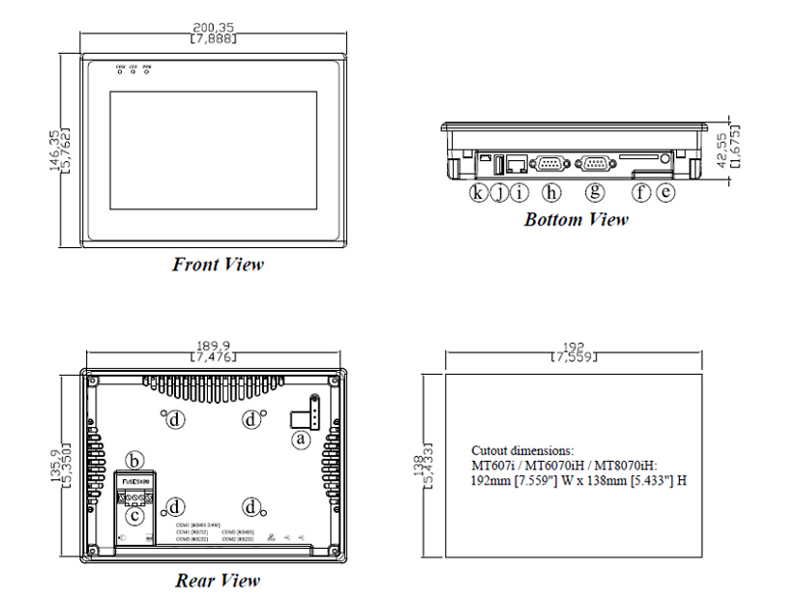
MT-600/8000 series
MT-607i
MT-8070iH / MT-6070iH
Installation Instruction
1.0 Installation and Startup Guide
Install Environment
Where
Used
The MT-600/8000 Series is designed for industrial. The temperature range of operating
is from 32 to 113 °F (0 to 45 °C), as majority of industrial environments. It may not be
suitable for using in certain outdoor applications. Please consult the factory for
advised usage in outdoor applications.
NEMA
Rating
The MT-600/8000 Series front bezel is NEMA 4 rated. When installed properly in a
NEMA 4 panel, the NEMA 4 rating of the panel will not be compromised. This means
that fluids will not enter the panel during wash downs.
Electrical
Environment
The MT-600/8000 Series has been tested to conform to European CE requirements.
This means that the circuitry is designed to resist the effects of electrical noise. This
does not guarantee noise immunity in severe cases. Proper wire routing and
grounding will insure proper operation.
Mechanical
Environment
Avoid installing units in environments where severe mechanical vibration or shocks
are present.
2.0 Installation Instructions
2.1 Mounting Instructions
2.1.1 Location Considerations
Care should be taken when locating equipment behind the unit to ensure that AC power wiring, PLC
output modules, contactors, starters and relays, and any other source of electrical interference are located
away from the back of the unit.
Particular note should be taken to the position of variable speed drives and switching power supplies.
Their input and load cables should be screened to a central star earth point.
1
2.1.2 Making a NEMA-4 Mounting
Panel
The unit can be mounted into panels with a depth of 4”(105mm). It is recommended that
Details
the unit be mounted on the front panel of a steel enclosure, through an appropriate
opening*. Allow a clearance of 1”(25mm) around the sides of the unit for mounting
hardware. Allow clearance for cable connections to the back of the unit. Unit depth may
vary according to cable type used. Typically, plan a depth to accommodate at least
4”(105mm) behind the panel.
NEMA-4
Mounting
Put the unit through the panel cut out. Slide the clamps into the 6~8 holes provided around
the case. Tighten the clamping screws in an even pattern until the unit is secured in the
panel.
Caution!
Do not over tighten mounting clamps!
Note:
Specifications
Note: To seal to NEMA-4 specifications, all supplied mounting clamps must be used and
panel cannot flex more than 0.010”.
2.1.3 Environmental Considerations
z
The MT-600/8000 are to be used indoors as built in displays. Make sure that the displays
are installed correctly and that the operating limits are followed (See Specifications).
z
Do not operate the unit in areas subject to explosion hazards due to flammable gases,
vapors or dusts.
z
The unit should not be installed where fast temperature variations and/or high humidity
are present. This will cause condensation of water in the device.
z
Do not install these terminals in environments where have inflammable gases.
2.2 Power Connections
Make sure that all local and national electrical standards are met when the installing the unit.
Contact your local authorities to determine which codes apply.
2.2.1 Power Requirements
Power
The MT-600/8000 can be powered by DC power only. The specified voltage
range is 24±20% Volts DC. This insures compatibility with most controller
DC systems.
The power conditioning circuitry inside the unit is accomplished by a
switching power supply. The peak starting current can be as high as 700mA.
Fusing
Requirements
If the display does not come on within 2 seconds of power up, remove
power. An internal fuse will prevent damage if the polarity of the DC power
is incorrect. Check wiring to insure proper connections and try to power up
again.
Caution
High Voltage
An Internal fuse will prevent damage for over voltage condition however it
isn’t guaranteed.
DC voltage sources should provide proper isolation from main AC power
and similar hazards.
Caution
Emergency
Stop
A Hard-wired EMERGENCY STOP should be fitted in any system using an
MT-600/8000 to comply with ICS Safety Recommendations.
2
Caution
Supply Voltage
Condition
Caution
Wire Routing
Caution
Do not power the MT-600/8000 and inductive DC loads, or input circuitry
to the controller, with the same power supply. Note: The 24 VDC output
from some controllers may not have enough current to power the
MT-600/8000.
Wire lengths should be minimized (Maximum 1600’ (500 m) shielded,
1000’ (300 m) unshielded).
Wires should be run in pairs with a neutral or common paired with a hot or
signal line.
If wiring is to be exposed to lightning or surges, use appropriate surge
suppression devices.
Keep AC, high energy, and rapidly switching DC wiring separate from
signal wires.
Equip ungrounded DC supplies with a resistor and capacitor in parallel to
earth ground. This provides a path for static and high frequency dissipation.
Typical values to use are 1MOhm and 4700pF.
To prevent the HMI from becoming damaged or having sound output issues,
after turning the device off, please wait 10 seconds before turning the device
on again.
Connection
To make a connection, strip about 3/8” of insulation off the end of the wire,
turn the connector screw counterclockwise until the gap is wide open, insert
the wire all the way in, and turn the screw clockwise until it’s tight.
Connect positive DC line to the ‘+24V’ terminal and the DC ground to the
‘0V‘ terminal.
2.2.2 Grounding Requirements
Chassis ground must be used. DC ground is not directly coupled to Earth
ground internally. It is preferable not to ground DC negative return to chassis
ground as poor site earths can introduce noise into a system, but if necessary
an earth connection should be made, from the power supply return point to
the central star earth point. Ground conductors should be as short and as large
in size as possible. The conductors must always be large enough to carry the
maximum short circuit current of the path being considered. Ground
conductors should be connected to a tree from a central star earth ground
point. This ensures that no ground conductor carries current from any other
branch.
2.2.3 CE Requirements
To make an MT-600/8000 comply with EMC directives, and to reduce susceptibility to electrical
interference, a separate #14 AWG ground wire should be taken to the chassis ground terminal of the
power connector. This ground connection should be run directly to the central star earth connection
point (as recommended in most Installation Instructions).
2.2.4 Safety Guidelines
This section presents recommended installation practices, and procedures. Since no two
applications are identical, these recommendations should be considered as guidelines.
Hardware
Considerations
WARNING!
The system designer should be aware that devices in Controller systems could
fail and thereby create an unsafe condition. Furthermore, electrical
interference in an operator interface, such as an MT-600/8000, can lead to
equipment start-up, which could result in property damage and/or physical
injury to the equipment operator.
If you, or your company, use any programmable control systems that require
an operator or attendant, you should be aware that this potential safety hazard
exists and take appropriate precautions. Although the specific design steps
depend on your particular application, the following precautions generally
3
apply to installation of solid-state programmable control devices. In addition,
these precautions conform to the guidelines for installation of Controllers as
recommended in the NEMA ICS 3-304 Control Standards.
Programming
Considerations
To conform with ICS Safety Recommendations, checks should be placed
in the controller to ensure that all writable registers that control critical
parts of plant or machinery have limit checks built into the program, with
an out-of-limit safe shut down procedure to ensure safety of personnel.
ICS 3-304.81 Safety Recommendations:
Consideration should be given to the use of an emergency stop function, which is independent of the programmable
controller.
Where the operator is exposed to the machinery, such as in loading or unloading a machine tool, or where the machine
cycles automatically, consideration should be given to the use of an electromechanical override or other redundant means,
independent of the programmable controller, for starting and interrupting the cycle.
If provision is required for changing programs while the equipment is in operation, consideration should be given to the
use of locks or other means of assuring that only authorized personnel can make such changes.
These recommendations are intended as safeguards against the failure of critical components and the effects of such
failures or the inadvertent errors that might be introduced if programs are changed while the equipment is in operation. *
z The ICS 3-304.81 Safety Recommendations are reproduced by permission of the National Electrical
Manufacturers Association from NEMA ICS 3-304
2.3 Communications Connections
The ports as you look at the back of the case, are the ports for connecting to a PLC or some external
device (Controller Connectors).
2.3.1 Connector COM1 [RS232], COM2 [RS232]
Cable
Requirements
Caution
Pin Designations
COM1 [RS-232]
COM2 [RS-232]
Different cables are required for various devices.
Restrict cable length to less than 500’ (150m) for RS485/422 devices and
50’ (15m) for RS232 devices to avoid communications problems.
The COM light on the front of the MT-600/8000 will turn on with each
Ethernet communication.
Shielded cable must be used for long lengths or cables run in an electrically
noisy environment.
Do not run cables next to AC power lines or near sources of electrical noise.
Be sure that the cable ends have been inserted all of the way into mating
connectors and are secure
Pin assignment of the 9 Pin, Male, SUB-D, COM1 [RS-232] and COM2
[RS-232] Port.
Pin#
Symbol
COM1 [RS232]
COM2 [RS232]
1
Not used
2
RxD
Received Data
3
TxD
Transmitted Data
4
TxD
5
GND
6
RxD
7
RTS
Ready to send output
8
CTS
Clear to send input
9
Not used
Transmitted Data
Signal Ground
Received Data
4
2.3.2 Connector COM1[RS485] , COM3[RS485] and COM3[RS232]
The 9 Pin, Female, SUB-D, COM1 [RS-485] , COM3 [RS-485] and COM3 [RS-232] Port on the back
of the unit is the RS-232 and RS485/422 communications port for connecting to a controller.
Connection
Pin Designations
COM1 [RS-485]
COM3 [RS-485]
COM3 [RS-232]
Pin assignment of the 9 Pin, Female, SUB-D COM1 [RS-485], COM3
[RS-485] and COM3 [RS-232] Port
Pin# Symbol Com1
Com1
Com3
Com3
[RS485]2w
[RS485]4w [RS485]
[RS232]
1
RxDataRx2
Rx+
Data+
Rx+
3
TxTx4
Tx+
Tx+
5
GND
Signal Ground
6
DataData7
TxD
Transmit
8
RxD
Receive
9
Data+
Data+
2.3.3 USB Host port
Support various devices with USB interface, such as mouse, keyboard, USB stick, printer…etc.
MT6000/8000 can download Project via the USB client port.
2.3.4 Connecter Wire
MT8-Ethernet/RZC045120: Direct connect (Ethernet crossover cable)
MT-600/8000
Ethernet
RJ45
Wire color
1 TX+
White/Orange
2 TXOrange
3 RX+
White/Green
PC or
Note Book
RJ45
3 RX+
6 RX1 TX+
6 RX-
2 TX-
Green
MT8-COM1/RZC002320
9
6
5
9
1
6
5
9
1
6
5
1
5
MT8-COM3/RZC004850
6
9
5
9
1
6
1
5
9
5
1
6
5
9
1
6
2.3.5 Dip Switch
SW1
ON
OFF
OFF
OFF
OFF
SW2
OFF
ON
OFF
OFF
OFF
SW3
OFF
OFF
ON
OFF
OFF
SW4 Mode
OFF Touch Screen Calibrate mode
OFF EB8000 System Tool Bar
OFF Boot Loader mode
ON Reserve
OFF Normal
z Touch Screen Calibrate and Reset Password mode: In
this mode when you power on the MT8000 series, the
screen will display a “+” sign at the center of the screen.
Use a stylus or finger to push the center of the “+” until
it moves. The “+” moves to upper-left, upper-right,
lower -left, lower-right and center. When all five “+” are
done the “+” will disappear. The Touch Screen
parameter will store at Flash Rom.
z
If losing or forgetting system passwords, users can set
Dip Switch 1 to “ON” position, the rest of Dips remain
on “OFF” position and then reboot MT8000 series.
Under this situation, MT8000 series will jump to Touch
Adjust (Touch screen calibration) mode. After
calibration, the pop-up window appears as the
illustration below. Users will be inquired if restoring the
system password to the default value.
z
When “YES” is chosen, another pop-up dialog appears
as below. Users will be confirmed again if restoring the
system password to the default value and will be asked
to input “YES”. Then click OK. (The default password
is 111111. However, other passwords, including
download and upload password, have to be reset.)
Note: When the reset action is be taken, projects and saved data in the HMI will all be cleared.
6
2.4 CE Requirements
EU directives that apply to the MT-600/8000 Series:
z EMC Directive (89/336/EEC, 92/31/EEC, 93/68/EEC) electromagnetic emissions and immunity
z Machinery Directive (89/392/EEC, 91/368/EEC, 93/44/EEC, 93/ 68/EEC) machine safety
z MT-600/8000 products will be CE-marked to indicate compliance with the EMC Directive.
The MT-600/8000 Series has been designed to operate satisfactorily in electromagnetic noise (immunity) and
without emitting high levels of electrical noise into the environment (emission). The units are designed to
meet European Community standards when installed per the wiring instructions in this manual.
Compatibility
Standards
The MT-600/8000 has been designed to meet electromagnetic compatibility for
industrial environments.
• CISPR (EN 55011) Group 1, Class A Radiated Emissions levels
• EN50081-2 Generic emission standard, industrial environment (Also US FCC Class
A)
• EN50082-2 Generic immunity standard, industrial environment
3.0 Specifications
MT6070iH
Display
Brightness
Color
Contrast Ratio
Resolution (WxH dots)
Back light
Backlight life time (avg.)
Touch panel
Touch Accuracy
I/O port
Ethernet port
USB
Audio
Processor
Flash memory
DRAM
SD card slot
RTC
Input Power
Max Power Consumption
Protection structure
Operating Temperature
Operation humidity
Enclosure
Dimensions WxHxD
Panel cutout dimension
Weight
Operating System
MT8070iH
MT607i
Hardware Specification
7" TFT LCD
300 cd/m2
65,536 colors
500:1
800 x 480
LED
30,000 hr. min.
4 wires resistive type
Active Area Length(X)±2%, Width(Y)±2%
COM1 (RS-232/RS-485 2W/4W), COM2(RS232), COM3(RS-232/RS-485 2W)
N/A
1 Ethernet port (10/100 Base-T)
USB Host port x 1, USB Client port x 1
N/A
1 x Audio Line Out
32bit RISC CPU 400MHz
128MB
64MB DDR2 RAM on board
N/A
YES
Built-in
General Specification
24±20% VDC
250 [email protected] Power Isolation Inside
IP65 front panel (O ring seal)
0~45°C
10-90% RH (non –condense)
Plastic
200 x 146 x 42.5mm
192 x 138 mm (7.5"x5.4")
Approx. 0.85 kg (1.87 lbs)
Operating System
EB8000 2.0.0 or Newer
Windows CE.net 5.0
7
3.1 Limited Liability Warranty
Weintek products include the isolated power supply are covered by a limited liability warranty from
defects in material and workmanship. This warranty does not apply :
(a) if, in the judgment of Weintek, the product fails due to damage from shipment, handling, storage, accident
(natural and man-mad) ;
(b) if the product fails due to misuse, including but not limit to incorrect set-up and wiring, current leakage
from machine platform and incorrect input power ;
(c) if the product has been maintained in a manner not conforming to product's instructions or has been
modified in any way,
(d) if the serial number has been defaced or removed.
4.0 Dimensions of MT-607i / MT-6070iH /
MT-8070iH
Bottom View
Front View
Cutout dimensions:
Cutout dimensions:
192mm [7.559"] W x 138mm [5.433"] H
192mm[7.559”]W x 138mm[5.433”]H
Rear View
a
DIP SW & Reset button
g
Com1[232], Com2[232]
b
Fuse
h
Com1 RS485, Com3 RS485, Com3 RS232
c
Power connector
i
Ethernet port (RJ-45) / MT6070iH N/A
d
VESA 75mm screw holes
j
USB Host port
e
Line Out (MT8070iH, MT607i)
k
USB Device port
f
SD card slot / MT6070iH N/A
8
- Описание
- Габариты
- Схемы
- Скачать
- Комплектующие
Технические характеристики панели MT6070iH
Дисплей
| Диагональ | 7″ |
| Разрешение | 800×480 |
| Яркость | 375 кд/м2 |
| Тип подсветки | LED |
| Время жизни подсветки | 30000 ч |
| Контрастность | 500:1 |
| Цветность | 65536 цветов |
| Тип сенсора | 4х проводной резистивный |
Параметры
| Процессор | 32bit RISC |
| Частота | 400 МГц |
| ОЗУ | 64 Мб |
| Flash ( встроенный ) | 128 Мб |
| RTC ( часы реального времени ) | Есть |
Интерфейсы
| Последовательный интерфейс | COM1 (RS232,RS485,2W/4W), COM2 (RS232), COM3 (RS232,RS485 2W) |
| USB хост | 1xUSB1.1 |
| USB клиент | USB 2.0 |
| Поддержка Modbus | RTU, ASCII, Master, Slave |
| Поддержка MPI | 187,5 K |
Конструкция
| Материал корпуса | Пластик |
| Охлаждение | безвентиляторное |
| Крепление | в щит, VESA 75×75 |
| Посадочное отверстие | 192×138 мм |
| Габариты | 200x146x42.5 мм |
| Вес (нетто) | 0.85 кг |
| Комплект поставки: | крепежные элементы, предохранитель, разъем питания, инструкция |
ПO
| ПО для разработки проектов | EasyBuilder8000 |
| Максимальное количество экранов в проекте | 1999 |
| Драйвера USB (для загрузки проекта с ПК в панель ) | устанавливаются при установке EasyBuilder8000 |
| Драйвера для работы с контроллерами | уже установлены в панели |
| Возможность сохранения архивов данных | память панели, флешка |
| Способы загрузки проекта в панель | с ПК по USB, с флешки |
| Максимальный размер проекта | 16 Мб |
| Объем памяти для сохранения архивов в панели | 48 Мб |
| Возможность создания пользовательских протоколов | Есть |
| Операционная система | возможно, она и есть в панели, но к ее функциям невозможно получить доступ. Невозможно запускать никакие пользовательские исполняемые файлы. Программист может пользоваться только теми возможностями, которые предоставляет EasyBuilder8000 |
Эксплуатация и хранение
| Рабочая температура | 0 ~ 50 ℃ |
| Потребляемый ток | 0.25А |
| Напряжение питания | 24 ±20% VDC (20-28 V) |
| Сертификаты | CE / FCC |
Если вы нашли ошибку, пожалуйста, выделите фрагмент текста и нажмите Ctrl+Enter.
Габариты панели MT6070iH
COM-порты панели MT6070iH
Название разъема:
COM1[RS232]
COM2[RS232]Тип:
DB-9 M ( Папа )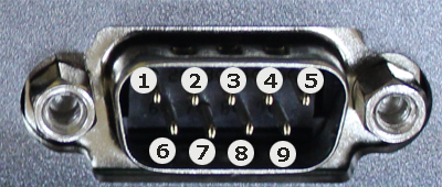
| Pin # | COM1 (RS232) | COM2 (RS232) |
| 1 | ||
| 2 | RXD | |
| 3 | TXD | |
| 4 | TXD | |
| 5 | GND | GND |
| 6 | RXD | |
| 7 | RTS | |
| 8 | CTS | |
| 9 |
Название разъема:
COM1[RS485 2/4w]
COM3[RS485]
COM3[RS232]Тип:
DB-9 F ( Мама )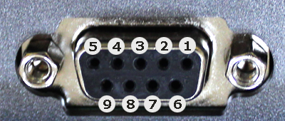
| Pin # | COM1 (RS485 2W) | COM1 (RS485 4W) | COM3 (RS485) | COM3 (RS232) |
| 1 | Data-(B) | RX- | ||
| 2 | Data+(A) | RX+ | ||
| 3 | TX- | |||
| 4 | TX+ | |||
| 5 | GND | GND | GND | GND |
| 6 | Data-(B) | |||
| 7 | TXD | |||
| 8 | RXD | |||
| 9 | Data+(A) |
Файлы для работы с панелью MT6070iH
|
Наименование |
Дата, размер |
Ссылка |
|
Брошюра на панель оператора MT6070iH |
01-08-2013 |
|
|
Руководство по установке панели MT6070iH |
01-08-2013 |
|
|
Программное обеспечение EasyBuilder8000 4.66.02.016 (рус) Программное обеспечение EasyBuilder8000 применяется для создания пользовательских проектов для операторских панелей Weintek следующих серий: |
21-12-2016 |
|
|
Руководство к ПО EasyBuilder8000 |
08-02-2016 |
|
|
Руководство по подключению контроллеров (PLC) к панели оператора MT6070iH В руководстве описано подключение к более, чем 100 PLC различных производителей, даны схемы распайки кабелей для подключения панели оператора MT6070iH к этим PLC, описаны регистры, к которым дают доступ драйвера данных PLC. |
06-04-2017 |
|
|
Чертеж панели оператора MT6070iH в формате sldprt |
10-10-2016 |
|
|
Чертеж панели оператора MT6070iH в формате wmf |
10-10-2016 |
|


Комплектующие панели оператора MT6070iH
Артикул: 13998
Категории: Weintek, Архив
Производитель оставляет за собой право изменять характеристики товара, его внешний вид и комплектность без предварительного уведомления продавца.

Снято с производства Заявка на подбор аналога
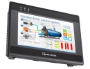
Графическая панель оператора 7″ / 65536 цветов / на базе RISC-процессора с частотой 400 МГц / интерфейсы: 1xRS-232 / 2хRS-232/485 / 2xUSB — Weintek MT6070IH
- Диагональ 7″
- Разрешение 800×480
- Цветность 65536
- ПО: EasyBuilder8000 (бесплатное)
- 3 порта RS232/RS485 / USB host
- Загрузка проекта:с ПК по USB / с флешки
Подробнее
Цены указаны с НДС
Уточните сроки
Нашли дешевле?
Оплата

По счету, банковской картой, наличными и QR. Подробнее
Жмите запросить цену
Оборудование со склада и под заказ
Конcультируйтесь +7 (343) 381-75-75, отправляйте спецификации ipcsales@aveon.ru
АВЕОН – дистрибьютор АСУ и IT | Собственное производство защищенных ПК
Техподдержка | Гарантия | Сервис | Доставка по России от 1 дня!
Самовывоз: Екатеринбург, Челябинск, Пермь, Тюмень, Ханты-Мансийск, Сургут
- Описание
- Характеристики
- Документация
- Зарегистрировать проект
- Оплата и доставка
Описание
Основные характеристики
|
Дисплей |
|
| Диагональ | 7″ |
| Разрешение | 800×480 |
| Цветность | 65536 |
| Тип сенсорного экрана | 4х проводной резистивный |
| Яркость экрана | 375 кд/м2 |
| Контрастность | 500:1 |
| Подсветка | LED |
| Время наработки на отказ подсветки, часов | 30000 |
|
Параметры |
|
| Тип процессора | 32bit RISC |
| Частота процессора | 400 МГц |
| Размер оперативной памяти | 64 Мб |
| Размер встроенной flash памяти | 128 Мб |
| Часы реального времени (Real Time Clock, RTC) | Есть |
| Рабочее напряжение | 20-28 В |
| Потребление тока | 0.25 А |
|
Интерфейсы |
|
| Последовательные интерфейсы | COM1 (RS232,RS485,2W/4W), COM2 (RS232), COM3(RS232,RS485 2W) |
| Поддержка Modbus | RTU, ASCII, Master, Slave, TCP/IP |
| Поддержка MPI | 187,5 K |
| USB Host | USB 1.1 |
|
USB клиент |
USB 2.0 |
| Поддержка SD карт | |
| Ethernet (LAN) | |
| Аудиовыход линейный | |
| Видео вход | |
| Интерфейс CAN (Controller Area Network) | |
|
Конструкция |
|
| Материал корпуса | Пластик |
| Степень защиты по фронту | IP65 |
| Способ охлаждения | безвентиляторный |
| Крепление | в панель |
| Посадочное отверстие | 192×138 мм |
| Габариты | 200x146x42.5 мм |
| Вес (нетто) | 0.85 кг |
| Рабочая температура | 0 — 50℃ |
| Комплект поставки: крепежные элементы, предохранитель, разъем питания, инструкция | |
|
Программное обеспечение |
|
| ПО для разработки проектов | EasyBuilder8000 |
| Максимальное количество экранов в проекте | 1999 |
| Драйвера для работы с контроллерами | предустановлены |
| Загрузка проектов | с ПК по USB, с флешки |
| Возможность установки ОС | Нет. Доступ к управлению панелью через ОС отсутствует, возможности ограничиваются функционалом EasyBuilder8000 |
| Максимальный размер проекта | 16 Мб |
| Размер выделяемой памяти под архив в панели | 48 Мб |
| Сохранение архивов | память панели, флешка |
|
FTP-доступ |
|
| Доступ по ftp к памяти панели | |
| Доступ по ftp к флеш-накопителю и SD карте | |
| Не рекомендуется к новым разработкам |
Характеристики
Дисплей
- Диагональ экрана (в дюймах)7
- Макс. разрешение дисплея800 x 480 точек
- Количество цветов дисплея65535 цветов
Интерфейсы ввода-вывода
- Портов RS-232/422/485COM1 (RS-232, RS-485, 2W/4W), COM2 (RS-232), COM3 (RS-232, RS-485 2W)
Программное обеспечение
- Совместимое программное обеспечениеEasyBuilder8000
Производство
- ПроизводительWeintek
Зарегистрировать проект
Зарегистрируйте проект, чтобы купить по специальной цене.
АВЕОН напрямую сотрудничает с производителями, поэтому вы можете зафиксировать проект за вашей организацией или за конечным заказчиком, получить скидку, запросить увеличение гарантийного срока.
Напоминаем, что все цены, опубликованные на данном сайте, приведены как справочная информация, не являются публичной офертой, определяемой положениями статьи 437 Гражданского кодекса Российской Федерации, и могут быть изменены в любое время без предупреждения.
Сертифицированные специалисты БЕСПЛАТНО помогут подобрать оборудование под ваш проект, составить спецификацию промышленного компьютера, порекомендуют актуальные замены для снятых с производства компонентов. Позвоните +7 (343) 381-75-75, напишите на ipcsales@aveon.ru или постучитесь в ЧАТ.
Вы можете заказать оборудование для тестирования на вашем предприятии, чтобы оценить характеристики и совместимость с уже установленными устройствами.
Самые ходовые компоненты АСУ ТП всегда на складе в Екатеринбурге и в Москве. Под заказ – 2 недели со склада в Тайване (при наличии у производителя). Самовывоз в Екатеринбурге, Челябинске, Тюмени и Перми. Доставка по России.
Условия оплаты
- Оплата заказов с сайта по безналичному расчету осуществляется по счету-оферте, который действителен в день его создания. В случае оплаты в последующие дни, стоимость заказа может быть пересчитана на дату оплаты по текущему курсу USD как ЦБ+2% по решению поставщика. При оплате по безналичному расчету с физических лиц может сниматься комиссия банка от 1%.
- Можно оплатить заказ наличными в офисе АВЕОН или при доставке курьером до двери.
- После оплаты выдается кассовый чек.
Условия доставки
- Доставка во все регионы России транспортными компаниями до терминала ТК в городе доставки, либо до двери заказчика.
- Срок доставки и стоимость определяются тарифами компаний-грузоперевозчиков.
- Также вы можете самостоятельно забрать товары из пунктов самовывоза в вашем городе.
Более подробная информация
здесь.
- Похожие товары
-
Промышленные компьютеры и периферия
- ПК в стойку 19″
- ПК настенно-настольного исполнения
- Серверы
- Панельные ПК и рабочие станции
- Мобильные решения
- Мониторы и LCD-панели
-
Клавиатуры
-
Встраиваемые решения
- Встраиваемые компьютеры
- Встраиваемые процессорные платы
- Оборудование Compact PCI
- Оборудование PXI/PXIe
- AdvancedTCA
- Процессорные модули и базовые платы
-
Коммуникационное оборудование
- Промышленные коммутаторы
-
Серверы последовательных интерфейсов
- Конвертеры и повторители
- Медиаконвертеры Ethernet Fiber
- Шлюзы протоколов
- Мультипортовые платы
- Беспроводное оборудование
- KVM-решения
- Системы видеонаблюдения
-
Системы сбора данных и управления
- Датчики, измерители
-
Контроллеры
- Модули удаленного ввода-вывода
- Платы ввода-вывода
- Панели оператора
- Платы и модули АЦП/ЦАП, крейты L-Card
- Нормализаторы сигналов
- Корзины расширения
- Выносные и платы клеммников
-
Комплектующие для промПК, сетей и АСУ
- Корпусы
-
Объединительные платы
- Материнские платы
- Источники и адаптеры питания
- Накопители
- Оперативная память
- Платы клеммников
- Разъемы и переходники
- Кабели
- Элементы крепежа
- Аксессуары к нормализаторам
-
Прочие аксессуары
- Шкафы, компоненты СКС
-
Программное обеспечение
- AdAstra TRACE MODE 6
- ПО Advantech
- ПО ICP DAS Indusoft, ISaGRAF
- Kaspersky
- Microsoft
- ПО MOXA MXview, SoftCmS, SoftNVR
-
Скидки! Распродажа!
-
Отраслевые решения
- Реклама
- ВПК
- Машинное зрение и IoT
- Медицина
- Морское применение
- Нефтяная и газовая отрасли
- Транспорт
- Энергетика
- Ритейл

Будьте в курсе!
Узнавайте о мероприятиях и акциях первым
Сравнить
В избранное
Технические
характеристики панели оператора Weintek MT6070iH
Дисплей
| Диагональ экрана | 7.0 ″ |
| Разрешение | 800×480 |
| Яркость | 375 кд/м2 |
| Контрастность | 500:1 |
| Тип подсветки | LED |
| Время жизни подсветки | 30000 час. |
| Цветность | 65536 |
Сенсор
| Тип сенсора | 4х проводной резистивный |
Параметры
| Процессор | 32 bits RISC |
| Частота | 400 МГц |
| Объем ОЗУ | 64 Мб |
| Flash (встроенный) | 0.125 Гб |
| RTC ( часы реального времени ) | Есть |
Интерфейсы
| USB хост | 1xUSB1.1 |
| USB клиент | USB 2.0 |
| Последовательный интерфейс | COM1 (RS232,RS485,2W/4W), COM2 (RS232), COM3 (RS232,RS485 2W) |
Конструкция
| Материал корпуса | Пластик |
| Охлаждение | безвентиляторное |
| Посадочное отверстие | 192×138 мм |
| Габариты | 200x146x42.5 мм |
| Вес (нетто) | 0.85 кг |
| Крепление на стену | есть |
| Комплект поставки | крепежные элементы, предохранитель, разъем питания, инструкция |
ПO
| ПО для разработки проектов | EasyBuilder8000 |
| Codesys | Нет |
| Максимальный размер проекта | 16 Мб |
| Объем памяти для сохранения архивов в панели | 48 Мб |
Эксплуатация и хранение
| Потребляемый ток | 0.25 |
| Напряжение питания | 24 ±20% VDC |
| Сертификаты | CE / FCC |
Габариты панели оператора Weintek MT6070iH
Габариты: 200x146x42.5 мм
Посадочное
отверстие: 192×138 мм

Схема
соединения Weintek MT6070iH
Название разъема:
COM1[RS232]
COM2[RS232]
Тип:
DB-9 M ( Папа )
| Pin # | COM1 (RS232) | COM2 (RS232) |
|---|---|---|
| 1 | ||
| 2 | RXD | |
| 3 | TXD | |
| 4 | TXD | |
| 5 | GND | GND |
| 6 | RXD | |
| 7 | RTS | |
| 8 | CTS | |
| 9 |
Название разъема:
COM1[RS485 2/4w]
COM3[RS485]
COM3[RS232]
Тип:
DB-9 F ( Мама )
| Pin # | COM1 (RS485 2W) | COM1 (RS485 4W) | COM3 (RS485) | COM3 (RS232) |
|---|---|---|---|---|
| 1 | Data-(B) | RX- | ||
| 2 | Data+(A) | RX+ | ||
| 3 | TX- | |||
| 4 | TX+ | |||
| 5 | GND | GND | GND | GND |
| 6 | Data-(B) | |||
| 7 | TXD | |||
| 8 | RXD | |||
| 9 | Data+(A) |
Файлы для работы
с Weintek MT6070iH
| Файл | Дата | Размер | Язык |
|---|---|---|---|
|
EasyBuilderPro — windows-приложение для программирования панелей оператора Weintek Программное обеспечение EasyBuilderPro применяется для создания пользовательских проектов для операторских панелей Weintek всех серий. |
Eng | ||
|
Руководство к ПО EasyBuilderPro Приложение EasyBuilderPro применяется для создания пользовательских проектов для операторских панелей Weintek |
28-12-2022 | 30.42 МБ | Eng |
|
Онлайн руководство пользователя EasyBuilder Pro на английском языке Приложение EasyBuilderPro применяется для создания пользовательских проектов для операторских панелей Weintek |
рус | ||
|
Руководство по подключению контроллеров (PLC) к панели оператора Weintek В руководстве описано подключение к более, чем 100 PLC различных производителей, даны схемы распайки кабелей для подключения панели оператора к этим PLC, описаны регистры, к которым дают доступ драйвера данных PLC. |
07-02-2018 | 31.1 МБ | Eng |