Руководство пользователя
3.5-дюймовый беспроводной видеодомофон

Беспроводной видеодомофон — это высокотехнологичный беспроводной интеллектуальный продукт 2.4G, объединяющий в себе функции дверного звонка, фотосъемки, внутренней связи, монитора и разблокировки.
Его удобная регулируемая камера-ангел расширяет кругозор пользователей. viewс. В частности, его уникальный датчик обнаружения человеческого тела будет обнаруживать людей, когда человеческое тело приближается к двери, и должен быть активирован внутренний монитор, показывать изображение снаружи на своем экране и автоматически делать снимок. Следовательно, даже если вас не было дома, вы также могли знать, кто вас навещал. Эта модель — гарантия безопасности вашего дома.
В этом продукте не используются провода. Удобен в установке и прост в использовании. Он специально разработан для вилл. Наружный блок может работать с тремя подобранными трубками с максимальным рабочим расстоянием 300 метров на открытой местности.
Использование новейших энергосберегающих технологий, его стабильная работа и модный внешний вид делают его лучшим выбором для вашей высококачественной интеллектуальной жизни.
Введение
Благодарим вас за выбор этого беспроводного видеодомофона. Пожалуйста, прочтите это руководство внимательно, чтобы полностью понять его использование, безупречные функции и простое управление.
Перед использованием этого продукта внимательно прочтите эти указания, чтобы обеспечить безопасную и правильную работу этого продукта.
Компания оставляет за собой право время от времени изменять это Руководство без предварительного уведомления.
Предупреждение о безопасности и внимание
- Не ставьте этот продукт на неровную или неустойчивую доску стола, чтобы предотвратить поломку или повреждение в результате падения.
- С этим продуктом можно использовать только аккумулятор и зарядное устройство, указанные Компанией.
Применение других продуктов может привести к утечке, перегреву, взрыву и возгоранию аккумулятора. - Не ударяйте, не трясите и не бросайте беспроводной видеодомофон во избежание поломки и возгорания беспроводного видеодомофона.
- Не кладите аккумулятор, зарядное устройство или беспроводной видеодомофон в микроволновую печь или устройство высокого давления; в противном случае возможно повреждение и возгорание электрической цепи, а также другие несчастные случаи.
- Не используйте этот продукт в местах с легковоспламеняющимися и взрывоопасными газами; в противном случае может произойти отказ продукта и возникновение пожара.
- Не размещайте этот продукт в местах с высокой температурой, высокой влажностью или большим количеством пыли; в противном случае может произойти сбой продукта.
- Не разбирайте и не переделывайте этот продукт, в противном случае это может привести к повреждению, утечке утечки или неисправности электрооборудования.
- Поместите крошечные металлические предметы, например булавки для рисования, в место подальше от динамика. Поскольку динамик обладает магнитными свойствами во время работы, он будет притягивать крошечные металлические предметы, что может привести к травмам или повреждению динамика.
- Не проецируйте объектив на сильный источник света, например солнце; в противном случае возможно повреждение датчика изображения.
- Не нажимайте на клемму объектива с большим усилием; в противном случае это может привести к травмам или повреждению устройства.
- Если продукт стал влажным по ошибке, выключите его, извлеките аккумулятор и перезапустите продукт, убедившись, что он полностью высохнет через 24 часа.
- Используйте чистую и сухую мягкую ткань для чистки линз, инфракрасный lamp, и датчик освещенности.
- ! Предупреждение: неправильная эксплуатация аннулирует гарантию!
Продукт закончилсяview
- Модный внешний вид — европейский дизайн, полный современной науки и техники, подходящий для домов с различными декоративными стилями.
- Скрытая антенна —— принять встроенную конструкцию антенны, эффективно защитить антенну.
- Очень большой диапазон обзора — 120 °
- Регулируемый угол наклона камеры — до 15 ° от центральной линии в любом направлении
- Цветной ЖК-экран высокого разрешения — используйте 3.5-дюймовый стандартный цифровой ЖК-экран TFT, обеспечивающий исключительную четкость.
- Высокоскоростная передача — скорость передачи изображения 25 кадров в секунду, изображение четкое и плавное.
- Инфракрасное ночное видение — инфракрасный свет должен включаться автоматически, когда внешний свет тусклый.
- 7 видов рингтонов —— пользователи могут свободно выбирать желаемые мелодии звонка.
- Функция монитора — проста и удобна в использовании, view сцены на открытом воздухе и делать фотографии, просто нажав одну клавишу.
- Автоопределение —— Камера включает в себя встроенный ИК-датчик, который активирует камеру и фотографирует посетителя, когда он приближается.
- Функция внутренней связи — может обеспечить двустороннюю связь между наружным и внутренним блоками, а также между двумя внутренними блоками.
- Функция разблокировки — удаленно разблокировать дверь с помощью монитора
- Автоматическая циркуляция памяти —— можно хранить 240 фотографий, автоматическая циркуляция
- Порт данных USB — зарядка или обновление программного обеспечения через порт USB
- Несколько опор —— настольное зарядное устройство
- Расширенная функция нескольких машин — поддержка максимум двух наружных блоков и трех внутренних мониторов.
- Передача на большие расстояния — расстояние связи может достигать 300 метров в открытом пространстве.
- Водонепроницаемый наружный блок —— IP55
- Питание переменного / постоянного тока — камера питается от переменного тока 9 ~ 16 В / постоянного тока 5 ~ 16 В
Рабочие параметры
| Наружный блок | Питания | Специальная литиевая батарея 3400 мАч |
| потребление | 400mA | |
| Размер структуры | 134’74’31 мм | |
| Вес | 122g | |
| условие внешней среды | Температура: -10 + 50 ° C | |
| Водонепроницаемый класса | IP55 | |
| размещение | Повесить на стене | |
| Поверхностный материал | АБС и аксессуары для оборудования | |
| камера | 300,000pixels | |
| View угол | Широкоугольный угол 120 ° (дополнительная регулировка 15 °) | |
| Схема ночного видения | Инфракрасный лamps | |
| ПИР | 3M * 100 ° | |
| Рабочее время | 3 часа непрерывно | |
| В режиме ожидания | 6 месяцев | |
| Время зарядки | 3hours | |
| Внешняя мощность | AC9-16V / DC5-16V |
| Внутренний монитор | Питания | Специальная литиевая батарея БП-6М (1100мАч) |
| потребление | 400mA | |
| Размер структуры | 126484’20 мм | |
| Вес | 110g | |
| условие внешней среды | Температура: -0т: — + 40т | |
| размещение | Стиль таблицы | |
| Размер ЖК-дисплея | Цветной TFT-экран диагональю 3.5 дюйма | |
| Режим беспроводной связи | 2.4GHz | |
| Распространение изображений | 25fps | |
| Формат изображения | PEG | |
| Рабочее время | 3 часа непрерывно | |
| В режиме ожидания | 300hours | |
| Время зарядки | 3hours | |
| Внешняя мощность | ДЦСВ СА | |
| Расстояние приложения | Около 300 м на открытом пространстве |
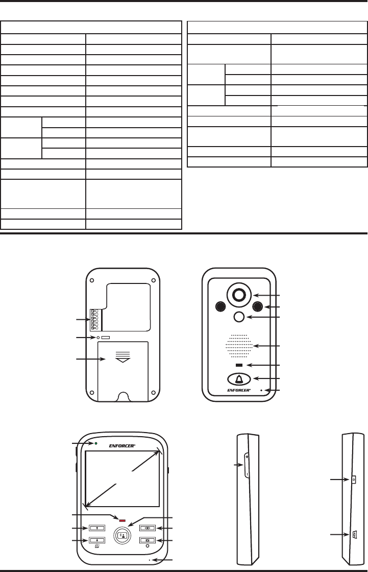
Диаграмма продукта
Наружный блок

Внутренний блок

Зарядная база для внутреннего блока

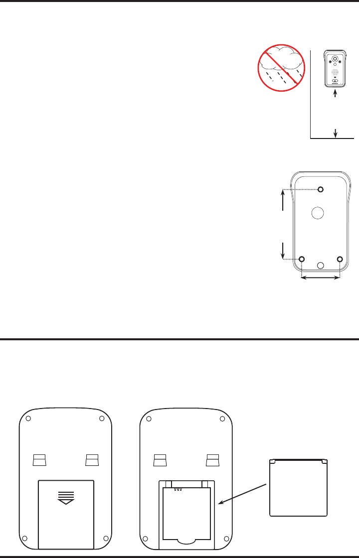
Руководство по установке
- Наружный блок следует устанавливать на высоте 1.4–1.7 метра над полом, избегая попадания прямых солнечных лучей. Не устанавливайте на металлическую стену, металлическую дверь или металлическую пластину, которые влияют на сигнал передачи.

- Этапы установки
A. Закрепите дождевик на стене с помощью шурупов.
B. Поместите наружный блок в дождевик и закрутите винт внизу.
- Подключите линию постоянного тока в соответствии со схемой подключения (диаметр отверстия для пропуска провода должен быть 16 ~ 30 мм). Красный провод (положительный полюс) подключается к точке 1; черный провод (отрицательный полюс) подключается к точке 2. Если питание осуществляется от сети переменного тока, подключите провод к точке 1 и точке 2.

- Подключение электронного замка и источника питания, как показано ниже: Если электрический замок всегда открыт: подключите к точке 4 Если электрический замок всегда закрыт: подключите к точке 5 Две линии питания замка: одна подключается к замку, другая подключает точку 6.
Примечание: электрозамок и источник питания должны быть подготовлены пользователем.
- Объектив камеры можно регулировать.


Внимание во время установки
- Внешний светочувствительный датчик не должен быть скрыт или заблокирован другими предметами.
- Не подвергайте наружный блок воздействию прямых солнечных лучей.
- Правильно подключите соединительную линию, в противном случае может быть отключен домофон.
Установка аккумулятора
- Сдвиньте крышку аккумуляторного отсека параллельно вниз и снимите ее.
- Вставьте батарею вместе с отсеком для батареи, обратите внимание на переднюю и обратную сторону батареи
- Установите крышку аккумуляторного отсека.


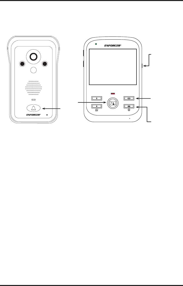
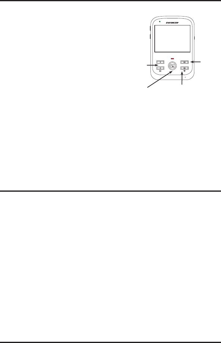
Функции клавиш внутреннего блока
 положите трубку / положите трубку и подтвердите
 Вариант вверх
 Вариант вниз, сделайте фото
 Правый вариант, меню, разблокировка
 Выход, монитор
- «ВКЛ / ВЫКЛ» Включение / выключение устройства.
- Клавиша громкости (+/-) Регулирует громкость внутреннего блока.
Инструкция по эксплуатации пользовательского интерфейса
- Включить / выключить
Наружный блок: Установите аккумулятор для включения. Выньте аккумулятор, чтобы выключить его. (DC / AC9-16V, литиевая батарея)
Внутренний блок: литиевая батарея БП-6М, зарядка через USB. Нажмите кнопку «вкл / выкл» примерно на 3 секунды, чтобы включить. И нажмите кнопку «вкл / выкл» примерно на 3 секунды, чтобы войти в интерфейс выключения: выберите «Да», чтобы выключить. - Пользовательский интерфейс внутреннего блока
Нажмите кнопку «МЕНЮ», войдите в главное меню,
 View& удалить фото. Можно хранить фотографии 240 шт. «A» означает автоматическую фотосъемку.
«M» означает ручную фотосъемку. «P» означает фотографии с датчика движения. «T» означает тревожные фотографии.
При заполнении памяти автоматически закроет самую раннюю фотографию. Сообщение о пропущенном звонке. Будет сообщение, если пропущен звонок или звонок. Может хранить не более 10 сообщений. Сообщение с фотографией (автоматическая фотосъемка). Автоматически закрывать самое раннее сообщение, когда более 10 сообщений. Новое сообщение не будет, если внутренний блок выключен или выключен.
 Установка времени и даты. Можно установить время, дату. Напримерample,12:00 01-06-2017.
 Настройка кольца. Есть 7 колец. Вы можете выбрать кольцо по своему усмотрению. Между тем, можно отрегулировать громкость звонка, нажав клавишу «+ -». Объем имеет 6 уровней.
 Выбор языка. Английский.
Заводским языком по умолчанию является английский. Параметр. Ввести настройки
A. Обнаружение движения. Откройте PIR или выключите.
Б. Время подсветки. Установка времени подсветки от 10 до 60 с, по 5 с на уровень, всего 10 уровней.
C. Время звонка. Установка времени звонка от 10 до 30, 10 с на уровень, всего 3 уровня.
D. Сопряжение: дать код, получить код
E. Версия: покажите номер версии прошивки.
Инструкция связи.
1. Внутренняя связь между наружным и внутренним блоками.
A. Нажмите кнопку «Вызов» на наружном блоке — внутренний блок покажет звонок ![]() на экране нажмите кнопку «ОК», чтобы ответить на звонок — покажет
на экране нажмите кнопку «ОК», чтобы ответить на звонок — покажет ![]() на экране. Можно домофон.
на экране. Можно домофон.
Б. Во время внутренней связи нажмите ![]() ключ, домофон без звука и шоу
ключ, домофон без звука и шоу ![]() на экране.
на экране.
C. Во время внутренней связи нажмите ![]() ключ для съемки видео. Это покажет
ключ для съемки видео. Это покажет ![]() на экране.
на экране.
D. Во время внутренней связи нажмите ![]() ключ, чтобы сделать фото и показать его
ключ, чтобы сделать фото и показать его ![]() на экране.
на экране.
E. Нажмите кнопку «+ -», чтобы отрегулировать громкость внутреннего блока, и покажите его. ![]() на экране.
на экране.
G. Во время внутренней связи показать![]() На экране внутреннего блока нижний аккумуляторный элемент предназначен для питания наружного блока, он будет красного цвета при низком уровне мощности.
На экране внутреннего блока нижний аккумуляторный элемент предназначен для питания наружного блока, он будет красного цвета при низком уровне мощности.
H.![]() номер обозначает разные внутренние блоки. Зеленые линии обозначают сигнал внутренней связи.
номер обозначает разные внутренние блоки. Зеленые линии обозначают сигнал внутренней связи.
I. В режиме ожидания нажмите кнопку ![]() контролировать снаружи.
контролировать снаружи.
J. PIR: при включении датчика движения камера наружного блока обнаруживает человека в пределах 2 метров и автоматически делает 3 фотографии для записи. Значок датчика движения![]()
К. Анти-тamper тревога наружного блока. Когда дождь накрывает отдельно от устройства, он подает сигнал тревоги с большим звуком. В то же время будет сделана запись фотографий 5 шт. Это покажет ![]() на экране.
на экране.
1. Внутренняя связь между внутренними блоками.
A. Если есть только 2 внутренних блока, нажмите![]() ключ и может вызвать другой внутренний блок.
ключ и может вызвать другой внутренний блок.
A. Если есть 3 внутренних блока, вызовите еще 2 внутренних блока. Нажмите ↑ ключ для вызова меньшего
Идентификационный номер внутренний блок. Нажмите кнопку, чтобы вызвать больший идентификационный номер. Внутренний блок. (Например,ample, чтобы вызвать внутренний блок ID2, нажмите. Чтобы вызвать внутренний блок ID3, нажмите кнопку.)
Шаги операции сопряжения.
Код совпадения 1V1 (поместите наружный блок рядом с внутренним монитором)
Выберите «код» в настройках на внутреннем мониторе — нажмите кнопку ОК — войдите в режим соответствия кода.
Между тем, нажмите и удерживайте «Отверстие для сброса» на задней стороне наружного блока, пока не услышите один звуковой сигнал, затем отпустите.
Когда на внутреннем мониторе отображается «Успешно», наружный блок издает три звука «ди-ди-ди», что означает успешное совпадение.
Если сопоставление не удалось в течение 16 секунд, внутренний монитор показывает «сбой», а наружный блок издает звук «ди». Повторите шаги, описанные выше.
ПРИМЕЧАНИЕ. По умолчанию монитор хорошо сопряжен с наружным блоком.
1V2 — Код соответствия
Выберите «Передать код» на первом сопряженном внутреннем мониторе — нажмите кнопку OK — войдите в режим передачи кода. На новом (втором) внутреннем мониторе выберите «получить код» — нажмите кнопку OK. Он будет иметь три звука «ди-ди-ди» и отобразить на экране «Успешно», что означает соответствие 1 мониторов в порядке.
1V3 — Код соответствия
Выберите «Предоставить код» на 2-х спаренных комнатных мониторах — нажмите кнопку OK — войдите в режим ввода кода.
На новом (третьем) внутреннем мониторе выберите «получить код» — нажмите кнопку ОК. Он будет иметь три звука «ди-ди-ди», и на экране отобразится «успешно», что означает соответствие 3 мониторам в порядке.
Добавить еще один наружный блок — совпадение кода 3-го
Выберите «Предоставить код» на любом сопряженном внутреннем мониторе — нажмите кнопку OK — войдите в режим ввода кода.
На новом (втором) наружном блоке: нажмите и удерживайте отверстие «сброс», пока не услышите «ди-ди», два звука. В случае успешного совпадения наружный блок издаст три звука «ди-ди-ди», что означает добавление 2-го наружного блока в порядке.
После согласования, пожалуйста, используйте наружный блок № 2, чтобы вызвать все внутренние мониторы для тестирования. если не в порядке, повторите вышеуказанные шаги еще раз.
Пакет включает
Ручной -–1
Дождевик -–1
Уличная камера -–1
Комнатный монитор -–1
Настольное зарядное устройство для монитора-1
Адаптер для уличной камеры DC5V -–1
Адаптер для внутреннего монитора -–1
Линия постоянного тока для уличной камеры -– 1
Линия USB для домашнего монитора -– 1
Литиевая батарея –2
Винты -–4
заявление
Стандартная конфигурация домофона — это один внутренний монитор и один наружный блок.
Домофон имеет готовое совпадение кода и может использоваться напрямую.
Если вам нужно больше внутренних мониторов или наружных блоков, пожалуйста, свяжитесь с вашим
местные дистрибьюторы (поддерживается максимум от 2 наружных блоков до 3 внутренних мониторов).
Для добавленных единиц, пожалуйста, ссылайтесь на коды передачи и получения в меню кодов.
Общие неисправности и решения
| Вина | Причина (ы) | Решение (я) |
| Не запускается | Забыли нажать кнопку переключателя | Нажмите кнопку переключателя |
| Литиевая батарея не установлена | Установите литиевую батарею | |
| Низкий уровень заряда батареи | Зарядите литиевую батарею | |
| Нет подключения к адаптеру питания, когда батарея разряжена | Подключите к адаптеру питания | |
| Не могу заряжать | Разъем адаптера неправильно подключается к порту зарядки устройства. | Подключите правильно |
| Адаптер не подключается к переменному току 110-240 В | Подключите к розетке для подключения к переменному току | |
| Наружный блок не может позвонить или подключиться к внутреннему монитору | Ошибка совпадения кода | Очистить код и повторно сопоставить код |
| Изображение шумное точка или мерцание |
Трубку ставят рядом с ТВ-плеером, СВЧ-печью, дневной свет лamp или мобильный телефон, излучающий электромагнитные волны. |
Держите трубку подальше от источников помех |
| Нет сигнала для Внутренний монитор |
Наружный блок не подключается к источнику питания | Подключитесь к источнику питания |
| Расстояние между наружным блоком и внутренним монитором слишком большое | Отрегулируйте до подходящего расстояния | |
| Нарушен магнитным полем вокруг | Держите трубку подальше от магнитного поля. |
Документы / Ресурсы

2.4GHz Digital
Wireless Video Door Phone
User Manual
Contents
1.
2.
3.
4.
5.
6.
7.
8.
9.
10.
11.
12.
●
●
Introduction ...................................................................... 2
Features ............................................................................ 2
Packing list ........................................................................ 3
Outdoor camera ................................................................. 4
Indoor monitor .................................................................. 4
Installation instructions ....................................................... 5
E-lock installation................................................................ 7
Operation........................................................................... 9
Working environment .........................................................14
Notices ...........................................................................14
Specifications ..................................................................14
Failure diagnosis ..............................................................15
Thank you for purchasing our product.
Please carefully read this user manual before using the product and
follow the manual to install and operate.
1
1. Introduction
3. Packing list
The product is applicable in office, house, apartment, hotel, building and so on.
The outdoor camera is easy to install. Indoor monitor is portable. It can be hung
on the wall, or be placed on the desk.
2. Features
(1)
2.4GHz digital frequency hopping and encryption technology, transmission
distance up to 400 meters in free field, robust anti-interference
(2) Clear night vision can capture image in low-illumination environment
(3) Rain shield for the outdoor camera is available
(4) 3.5 or 7 inch TFT color panel for indoor monitor
(5) Surveillance, unlock, hands-free call and talk
(6) 16 chord melodies and melody volume is adjustable
(7) Brightness and talk volume are adjustable
Outdoor camera part
(8) Date (only one camera with one monitor system) and time shown on the screen
(1) Outdoor camera (2) Power adapter Input: 100-240V 50/60Hz Output: 5V/1A
(9) Indoor monitor could take pictures automatically or by instruction. It could store
(3) double-sided tape (4) Wireless unlock control (5) Screws and stoppers
up to 100 pictures with date and time
(6) DC cable
(10) BL-5J battery of camera and monitor is replaceable and rechargeable
(11) Outdoor camera works about 30 days if with battery. It works all the while if
connected with the 2w solar module. Or it works all the while if power adapter
is connected.
(12) Wireless unlock control supports power on and power off unlock
(13) One outdoor camera supports up to 4 indoor monitors and vice versa
(7) Remote control (optional)
(8) BL-5J battery (optional)
(9) Solar module charger (optional)
(10) 6meters or 10meters antenna
Indoor monitor part
(11) 3.5” indoor monitor or 7” indoor monitor
(12) Fixed iron for 7” indoor monitor (13) BL-5J battery (14) USB Cable
(15 ) USB power adapter; Input: 100-240V 50/60Hz Output: 5V/1A (16) User manual
2
3
4. Outdoor camera
(1) Microphone
(2) Camera lens
(B) 7” indoor monitor
(3) Rain shield
(4) Infrared light
(5) Indicating light for recharge
(6) Indicating light, show green if press ‘pair’ or ‘call’ button, show red if low voltage
(7) ‘Call’ button
(8) Speaker
(11) Battery lid of BL-5J
(9) Adapter interface (10) ‘Pair’ button
(12) Obligate area welding antenna
(1) Speaker
(2) TFT screen
5. Indoor monitor
(5)
‘Monitor’ button
(8)
Left
(A) 3.5” indoor monitor
(12) Working light (13)
(9) ▼Down
(6)
’Unlock’ button (7)
(10)
’Talk’ button
Right (11) charging light
‘Take picture ’ button (14) ▲Up
(16) Power switch (17) Fixed slot
6.
(3) Antenna (4) Microphone
(15) USB interface
(18) Battery lid of BL-5J (19) Bracket
Installation instructions
The outdoor camera should be installed at the shielded position to be free from
direct shinning of strong light or raining. The height for installation is recommended
to be 1.5~1.7m for outdoor camera to focus on the best monitoring range. Wireless
signal will be weakened if there are obstacles between the outdoor camera and the
indoor monitor. Please check the best sign of monitor when install the outdoor
camera to get the best position.
4
5
If wiring needs to go through wall, the plug should be firstly wrapped with tape so
as to avoid the sand or dirt going into the plug thus resulting in malfunction.
Use double-sided tape fix camera on the wall or door as the following diagram.
Take off the screw on the bottom, remove the back box fit on the wall, embed the
camera to the back box and use screws to fix as the following diagram.
7.
E-lock installation
E-lock and power of e-lock are not included in this product. Wireless unlock
control connects e-lock, shares 12V power adapter with e-lock when it works.
If it is inconvenient for the user to install power adapter near outdoor camera,
user can also select solar panel module and rechargeable battery for outdoor
camera. But the solar panel module and rechargeable battery are not included in the
product package list.
The Vmp and Imp of the 2w solar panel module are 5v and 400mA respectively.
The wire between solar panel module and camera length is 6 meters. You’d
better put the solar module on the place the sun can directly shine. The battery
costs 3~4hours to be fully charged by strongly directly shinning. Outdoor camera
can work about 30 days each full recharge.
6
7
Notes: The distances between wireless unlock control and outdoor camera
should be within 10 meters so that the wireless unlock control is able to receive
unlock command. The remote control uses 27A/12V battery.
presses
of
remote control to unlock. The work distance between remote control and unlock
8.
control should be within 15 meters.
Schematic diagram
Operation
Note: When the system is in working condition, if there is no blocking wall
between indoor monitor and outdoor camera, you must keep them at least 6
meters apart to avoid the ‘whistle’ sound.
A Setting
(1) Date and time
When indoor monitor is in non-talk mode, press
button for 3 seconds, there
will be a "T" (for time) character on the left side of the battery symbols on the screen.
User can set the date (year/month/day) and the current time (hour/min). Time format
is 24 hours. Only one outdoor camera with one indoor monitor is available for date
setting. Press
,
button to select,
press ▲, ▼ button to adjust the date and
time in grey.
The system can work together with intelligent lock, Intelligent lock uses 4pcs AA
batteries.
8
9
(2) Talk, unlock
(2) Melody and volume
When indoor monitor is in non-talk mode, press
chord melodies as the sound of the bell. Press
button to select one of the 16
choose to the volume of
melody
The visitor presses the “call” button of the outdoor camera. All indoor monitors will
sound melody.
A. Press
(adjust level: 1-2).
button of one indoor monitor to speak to visitor before unlock.
Other indoor monitors can see the image but can not hear sound of the visitor.
16 chord melodies are Ding-dong, To Alice, Westminster bell, Butterfly lovers, The
cygnet, Red river valley, My heart will go on, Turkey’s march, Small dance,
If you want to let other indoor monitor to talk, press
Congratulations you, William's prelude, Love romance hudson, Memory, The Little
current dialogue, then another indoor monitor could press
Mermaid, Green sleeves, Romeo and Juliet.
speak to visitor.
When in talk mode, press
(3) Talk volume
In the talk mode, press
to adjust the talk volume. Adjust level: 0-7.
button to
button to unlock the door lock, the unlock signal
shows on the screen. When press
,
button to end the
button again, the unlock signal will
disappear.
Press
button to turn off the screen and enter standby mode, or it will turn into
standby mode automatically after 30 seconds.
(4) Brightness
In the talk mode, when indoor monitor has dynamic image from outdoor camera,
press ▲, ▼ to adjust brightness. Adjust level: 0-7.
B.
If do not want to let the visitor go in after seeing the video, no operation or
press the
button to turn off the screen and then enter into standby mode.
Indoor monitor enters into the standby mode after 30 seconds if no any operation.
Note: if you use multiple indoor monitors, please keep distance among indoor
B
Operation
monitors to avoid affecting talk effect.
(1) Indoor monitor turn on/off
Turn on:
Turn the power switch to “ON”, working light display red and rings the
melody.
Turn off:
Turn the power switch to “OFF”, working light off。
Maximum Com-sign is level 6. Maximum battery bar is level 4.
(3)
Monitor
For one outdoor camera or more outdoor cameras with one indoor monitor, if
there is no calling from the outdoor camera, the indoor monitors are in standby
mode. User can press the
button once to wake up the indoor monitor; press
button again to enter monitor mode and monitor the outdoor as long as you like,
monitor signal will display on the screen. Press
button again to quit and turn off
the screen.
For several outdoor cameras with one indoor monitor, in monitor mode,
press
button to show the image from the CAM1, CAM2, CAM3, CAM4 (if the system
has) in sequence. At the last outdoor camera, press
turn off the screen.
10
11
button again to quit and
(4) Charge
indoor monitor.
For the first time, the battery should be charged for more than 5 hours to activate
the lithium battery. After that charge 3 hours every time, Charging led is red when
(2) One outdoor camera and up to 4 indoor monitors system is 1VN system
Firstly, press ‘pair’ button of outdoor camera, indicating light flash, press
charging, it turns green when the battery is filled, the color of battery bar will change
and
from green to red when the battery is in low power.
pairing”. If pairing succeeds, the video from outdoor camera will be shown in the
C
button of indoor monitor at the same time, the screen will show “... 1v4
screen of indoor monitor.
Picture
Secondly, repeat the above operation for each indoor monitor.
(1) Take pictures
(3) Up to 4 outdoor cameras and one indoor monitor system is NV1 system
When there is video from outdoor camera, presses
button to take a picture,
one press captures one picture.
Note: To pair this system is more complex than to do the above two systems.
After turn on outdoor camera and indoor monitor, press button ASAP so not
When the Call button of outdoor camera is pressed, if the user isn't in or no
operation, all indoor monitors automatically save the image from camera after 10
let any part enter into standby mode.
Firstly, press the ‘pair’ button of outdoor camera, indicating light flash, press
seconds. The new picture will replace the first picture if no memory is available.
and
(2) Browse pictures
pairing”, if pairing succeeds, the video will be shown in the screen of indoor monitor.
In the non-talk mode, press
press
,
button to browse the stored pictures, then
button of indoor monitor at the same time, the screen will show “... 4v1
Secondly, repeat the above operation as soon as possible until finish all pairing.
Thirdly, check whether pairing is successful, let system power on again, and then
button or after 10 seconds to quit browse mode.
press ‘monitor’ button continuously to monitor each outdoor camera. If each outdoor
(3) Delete pictures
camera works, it means that system pairs successfully. Otherwise repeat the first
Firstly turn off the indoor monitor, then press
about 5seconds, then turn on the indoor monitor,
and
button together
text: ’Delete all photo, please wait’ ‘no photo , Please Power off’. After that all
pictures have been deleted. Please turn off the indoor monitor.
D
step.
until the screen displays
2 Pair unlock control with door phone system
Unlock control is connected to 12V power adapter. Outdoor camera uses the
battery, or is connected to the power adapter. Firstly press the pair button of unlock
Pair
control, the pair light will flash once. Press the
under talk mode, pair light will continuously flash.
pair ok before use get the product.
Once again press the pair button of unlock control, pair light stops flashing.
1 Pair outdoor camera with indoor monitor
Note: The system only support 3 models as below. User can’t mix them when
purchase. For one-to-one system, adding more outdoor camera or more
indoor monitor can’t become one-to-multiple system.
and
button of indoor monitor at the same time, the screen will show “... 1v1 pairing”. If
pairing succeeds, the video from outdoor camera will be shown in the screen of
12
Finally press the
button of the indoor monitor under talk mode, the pair light
will flash 3 seconds, it means that pairing is successful.
3 Pair remote control with unlock control
(1) One outdoor camera and one indoor monitor system is 1V1 system
Press ‘pair’ button of outdoor camera, indicating light flash, press
button of the indoor monitor
Unlock control is connected to 12V power adapter. Firstly press the pair button of
unlock control, pair light will flash once. Press the
button of remote control, pair
light will continuously flash.
Once again press the pair button of unlock control, pair light will stop flashing.
13
Finally press the
button of remote control, the pair light will flash 3 seconds,
it means that pairing is successful.
9.
Failure diagnosis
Malfunction
Working environment
Fail to start the
(1) Working temperature: -15℃—+55℃
10.
12.
(2)
Working humidity: ≤85%
product
If the power adapter correctly
Re-insert the plug to make
get through the 100-240V AC
power adapter get AC
electricity?
electricity.
No voice in talk
If the talk volume is adjusted to
To adjust the talk volume to
mode
be the least?
be suitable.
Fail to charge
flashing or
noisy
Camera
Light
Source
Indoor monitor
USB
6 LED lights
Power
microwave oven which has
magnetic wave?
Output:DC 5V/1A
If the outdoor camera is far
3.5”TFT 320×240
Battery
Power
Solar moudle, battery or
Power
Battery or 5V 1A power
supply
5V 1A power adapter
supply
adapter
7”TFT 800×480
BL-5J 1250mAh
No signal for
indoor monitor
away from the indoor monitor?
If there is other strong
magnetic space bother?
3.5” 141×87×20 mm
7” 236×130×18 mm
Standby
tape
or
screw fix
35 days
Installa
tion
Standby
Place on the desk etc.
Or wall mounting type
3.5” 20 days
7” 4 days
14
magnetic wave.
the outdoor camera
BL-5J 1250mAh(option)
Double-sided
from these things which has
connect the power?
Battery
Installatio
n
Keep indoor monitor far away
50/60Hz
Screen
Size
induction cooker and
To connect power adapter to
CMOS 300K pixels
126×93×42 mm
If the indoor monitor is close to
If the outdoor camera doesn't
Input:AC 100-240V
Camera
Size
Charge the Li-on battery
with power adapter
The image is
Specifications
If the power of Li-on battery is
correctly?
model (same standard voltage and current).
11.
Turn the switch to the ON
Re-connect indoor monitor
(2) Please always use the specified power adapter, or that with the same
covers may expose you to dangerous voltage or other hazards.
If turn the switch to the "ON"?
If the plug of power adapter
working mode.
(3) Do not attempt to service this product yourself as opening or removing
Debug
not enough?
Notices
(1) Please don’t cover anything on the Microphone or speaker when it is in
Checking
15
Keep the distance in 60
meters within (stopped by
multi-wall)
Keep indoor monitor far away
from the strong magnetic
space
11. Failure diagnosis
Malfunction
Checking
If turn the switch to the «ON»?
Fail to start the
If the power of Li-on battery is
product
not enough?
If the plug of power adaptor
correctly plug into mini-USB?
Fail to charge
If the power adaptor correctly
get through the 100-240V AC
electricity?
No voice in talk
If the talk volume is adjusted to
mode
be the least?
If the indoor monitor is close to
The image is
induction cooker and
flashing or
microwave oven which has
noisy
magnetic wave?
If the outdoor camera doesn’t
connect the power?
If the outdoor camera is far
No signal in
away from the indoor monitor?
If there is other strong
magnetic space bother?
Debug
Turn the switch to the ON
Re-connect indoor monitor
with power adaptor
Re-insert the plug to make
power adaptor get AC
electricity.
To adjust the talk volume to
be suitable.
Keep indoor monitor far away
from these things which has
magnetic wave.
To connect power adaptor to
the outdoor camera
Keep the distance in 60
meters within (stopped by
multi-wall)
Keep indoor monitor far away
from the strong magnetic
space
11
2.4GHz Digital
Wireless Video Door Phone
User Manual
● Thank you for purchasing our product.
●
For better taking advantage of the prior functions please carefully
read user manual for correct installation and operation.

xWireless operation – camera and monitor can
operate from up to 492ft (150m)2 away
xCamera has built-in IR LEDs for nighttime
operation
xRemotely and securely talk to visitors and
unlock doors or gates via the monitor
xLightweight monitor can be carried around
premises while talking to the visitor
xConnect up to two additional monitors1
xCamera includes a built-in PIR sensor that
activates the camera and takes
visitor when he or she approaches
xMonitor includes a kickstand and a charging
base
xCamera powered by 5VDC
xMonitor front door at any time
xEgress input
x120° wide viewing angle
1Second and third monitors sold separately.
2Line-of-sight range. Actual range may vary depending on the installation and operating environment.
Wireless Video Door Phone

ENFORCER Wireless Video Door Phone
2SECO-LARM U.S.A., Inc.
Introduction ………………………………………………. 2
Parts List
…………………………..
……………………… 2
Also
Available …………………………..
………………. 2
Specifications
…………………………..
……………….. 3
Overview
…………………………..
……………………… 3
Display Overview
…………………………..
………….. 4
Installation Notes
…………………………..
………….. 4
Camera Wiring Diagram
…………………………..
…………………………..
……….. 5
Installation
– Camera …………………………..
Installation – Monitor ……………………………….. 6-7
Programming
…………………………..
……………….. 8
Operating the Wireless
Video Door Phone ……………………………… 9-
onitors ………………………..
and Pairing a First Monitor ……………………..
………………………………………….
……………………………………….
12
Warranty ………………………………………………… 12
The ENFORCER Wireless Video Door Phone is the convenient and secure way to monitor and
control an entryway such as a door or gate from nearly 492 feet (150 meters) away.
When a guest or visitor presses the doorbell button on the camera unit, the homeowner can use
one of up to three lightweight wireless LCD monitors to see who is requesting entry, speak with the
caller, take a photo, and decide whether or not to grant entry.
1x Monitor (DP-236MQ)1
1x
Camera (DP-236CQ)1
Monitor charger stand
Monitor kick stand
AC Power adapter with USB port (for monitor)
USB Cable (for monitor)
Rechargeable lithium ion batteries
(for monitor and camera)
AC Power adapter with DC plug (for camera)
DC Jack with pigtail (for camera)
Mounting screws
Screw anchors
Camera screw
Screw cover
Monitor charger stand
Monitor kick stand
AC Power adapter with USB port
(for monitor)
USB Cable
Rechargeable lithium ion battery
Replacement Monitor Charger Stand
1 By default, the monitor in the
DP-236Q Complete Kit is paired
with the camera.
2 Additional monitors are not
automatically paired with the
camera. See pg. 10, Pairing
ENFORCER Wireless Video Door Phone
SECO-LARM U.S.A., Inc. 3
5VDC
Dimensions
16
8
8
(144x80×60 mm)
Operating voltage
5VDC (adapter) or
3.7VDC (battery)
2.411-2.471GHz
Dimensions
*Line-of-sight range. Actual range may vary depending on the
installation and operating environment.
Wiring connections
(see pg. 4)
—
ON/OFF
—
— Unlock door
2410.875-2471.625MHz

ENFORCER Wireless Video Door Phone
4SECO-LARM U.S.A., Inc.
1. Unpack the video door phone and note the included parts.
2.
Read this manual thoroughly. A clear
understanding of the manual will make installation and
operation much easier.
Find a good location to mount the monitor and camera.
4. Avoid mounting the camera or monitor near sources of strong electromagnetic signals or other
electronic devices that may cause interference.
Avoid mounting the camera in direct sunlight or exposing the camera to strong vibrations,
rain, or moisture, which could result in damage to the camera.
The monitor and camera contain no user-serviceable parts. Opening them may damage
sensitive components and will void the warranty.
: Signal Strength – Displays the wireless signal strength
: Time
– Displays the current time
– Displays when the PIR sensor is turned on
– Displays if the ringer is audible or muted
– Displays when there is a missed call
-Way Communication – Displays when the monitor and camera station can hear
each other
– Displays while the relay is active
: Camera Battery: Displays the
current camera station battery level
: Monitor Battery: Displays the current monitor station battery level

ENFORCER Wireless Video Door Phone
SECO-LARM U.S.A., Inc. 5
Negative (-) (black wire)
1) Positive (+) power input. Connect to the red wire of the included AC adapter or to the positive
wire of the doorbell’s power supply.
Negative (-) power input. Connect to the black wire of the included AC adapter or to the
negative wire of the doorbell’s power supply.
Egress (N.O.) negative input. Connect to an optional N.O. egress device. The egress device
will activate the relay for the same length as the lock delay. (See pg. 8, Programming the
lock delay).
N.O. (Normally opened) output. Wire to the lock device for fail-secure operation.
N.C. (Normally closed) output. Wire to the lock device for fail-safe operation.
Common output. Wire to the power supply of the lock device.
For 16VAC doorbell installation, wire directly from the doorbell’s transformer.
Fail-secure
electric strike
Electric strike
power supply
xThe camera is connected to its included AC adapter.
x
The egress input is connected to a Request-to-Exit Plate. The homeowner can exit the
premises by pressing this button.
The N.O. (normally open) output is wired to an electric lock. The camera and the Request-to-
Exit Plate both activate the strike, allowing entry or egress.
xThe electric lock’s power supply is wired to the COM (common) output.
To the included AC adapter or
the doorbell’s transformer
ENFORCER Wireless Video Door Phone
6SECO-LARM U.S.A., Inc.
1. Position the camera so the area to be monitored is easily visible,
optimally 5ft (1.5m) above the ground. Do not position the
camera in direct sunlight, or where it will be exposed directly to
rain or snow.
NOTE: For best results, the visitor should stand 2.5~5ft
(0.8~1.5m) away from camera. (at least 20 cm must be maintained).
2. Cut a hole large enough to run the min. 21AWG 2-conductor
wire to the door unlock device through the wall, as well as to the
included power supply.
3. Install the camera bracket to the wall with three screws. Use
screw anchors if the bracket is mounted on drywall or brick.
4. Run the 2-conductor wire from the camera through the wire hole
in the bracket to the optional door unlock device.
5. Install the rechargeable lithium ion battery into the camera. The
battery will act as a backup power source in case of a power
outage.
6. Connect the AC adapter (see Camera Wiring Diagram on pg. 5).
7. Mount the camera into the bracket:
oPush the top of the camera into the top of the bracket.
oPush the bottom of the camera into the bottom of the
bracket.
oScrew in the bottom of the camera to fix the camera into
the bracket and push the plastic screw cover into the
bottom of the bracket, over the screw.
NOTE: Do not block the PIR sensor on the camera.
5ft
(1.5m)
33/4”
(96mm)
22/16” (54mm)
Install the monitor battery:
Remove the battery cover on the back of the monitor and insert the included
BP-6M lithium ion battery.
BP-6M
Installation – Monitor:
Installation – Camera:

ENFORCER Wireless Video Door Phone
SECO-LARM U.S.A., Inc. 7
Installation – Monitor (continued):
Recharge the monitor battery:
There are two ways to recharge the monitor battery.
monitor into
the monitor
charger stand
and plug the
charger into
the stand.
2. Plug the charger directly into the monitor.
Turn monitor ON:
Hold the “ON/OFF” button for 3 seconds. The monitor will turn
ON with the ENFORCER screen.
mode:
If the monitor is on, press the “ON/OFF” button momentarily to
go to standby mode (if the display is ON) or
to leave standby
display is OFF).
The red indicator LED will flash once every three seconds in
standby mode.
attery saver:
If the display is ON and there is no user action for 35 seconds,
the display will turn OFF and the monitor will go into standby
mode.
When the battery is low (indicated by 1 or 0 bars on the
display’s battery icon), the red indicator LED will start to flash
once per second.
While the monitor’s display is ON, hold the “ON/OFF” button
for 3 seconds and the
monitor will turn OFF.
Low
battery
level

ENFORCER Wireless Video Door Phone
8SECO-LARM U.S.A., Inc.
1. While the monitor display is on, hold the “Photo/Settings” button for 3 seconds to enter
programming mode.
Press the “Photo/Settings” button to cycle through the programming options, including:
a. Time setup
b. Ringtone choice
c. Lock delay
d. PIR setup
To exit programming mode, press the “Photo/Settings” button to cycle through the remaining
programming modes, or press the “Talk” button to return to the home screen.
NOTE: If there is no activity, the monitor will exit programming mode and the disp
off in 35 seconds.
Programming the display time:
Hold the “Photo/Settings” button for 3 seconds
to enter programming mode.
Use the up and down arrow buttons on the
front of the monitor to highlight the area to be
changed.
Use the volume buttons (+/-) to adjust the time
or date.
Press the “Talk” button to set the display time
and exit programming mode.
Programming the ringtones:
Hold the “Photo/Settings” button for 3 seconds to enter programming mode, then
momentarily press the “Photo/Settings” button one time to select the ringtone display.
Use the up and down arrow buttons on the front of the monitor to choose one of 4 ringtones:
Telephone, Doorbell, “Für Elise”, or “Jingle Bells”. This is the tone the user will hear when a
visitor requests entry.
Use the volume buttons (+/-) to adjust the volume of the ringtone.
Press the “Talk” button to set the ringtone and exit programming mode.
Programming the lock delay:
This determines how long the relay output is active after the door has been unlocked.
Hold the “Photo/Settings” butt
on for 3 seconds to enter programming mode, then momentarily
press the “Photo/Settings” button two times to select the lock delay.
2. Use the up and down arrow buttons on the front of the monitor to set the lock delay from 1 to 6
seconds. The default setting is 1 second.
Press the “Talk” button to set the lock delay and exit programming mode.
Programming the PIR sensor ON/OFF:
-in PIR (passive infrared) sensor to detect an approaching visitor and
automatically turns the camera on and capt
ures a photo. It can be programmed ON or OFF.
1. Hold the “Photo/Settings” button for 3 seconds to enter programming mode, then briefly press
the “Photo/Settings” button three times to select the PIR mode.
Use the up and down arrow buttons on the front of the monitor to turn the PIR sensor ON
or OFF.
3. Press the “Talk” button to set the PIR sensor and exit programming mode.
ENFORCER Wireless Video Door Phone
SECO-LARM U.S.A., Inc. 9
1. If a visitor presses the
doorbell button on the camera, the monitor’s display turns ON and the
monitor sounds the chosen ring tone.
2. To talk with the visitor, press the “Talk” button.
3. To unlock the optional electronic door lock, press the “ON/OFF” button briefly while the
monitor is displaying the camera’s view.
4. Press the “Talk” button again to turn off the monitor.
View and/or talk to a visitor who has not pressed the doorbell button on the camera:
1. Press the “ON/OFF” button to turn the monitor’s display ON.
2. Press the monitor’s “View” button to turn the camera on. At this time, the monitor can hear
sound and view video from the camera.
3.
Press the monitor’s “Talk” button to enable communication between the monitor and camera.
4. To unlock the optional electronic door lock, press the “ON/OFF” button
monitor is displaying the camera’s view.
NOTE: The “Talk” button must be pressed before pressing the “ON/OFF” button
pressing the “ON/OFF” button will turn off the monitor.
5. Press the
monitor’s “View” button to mute the monitor or “Talk” button to end monitoring of the
camera.
1. While the monitor is displaying the camera’s view, press the “Photo/Settings” button to
manually take a photo.
2. If the user does not answer a call within 5 seconds, the camera will take a photo
automatically.
NOTE: If the monitor’s battery is low, the photo-taking function will not work.
1. Press the doorbell button on the camera.
2. Wait for someone to press the “ON/OFF” button on the monitor to unlock the door.
Settings
x
ON/OFF
xStandby
mode
xUnlock door
Operating the Wireless Video Door Phone:
ENFORCER Wireless Video Door Phone
10 SECO-LARM U.S.A., Inc.
Adjust the monitor’s color tint:
1. Press the “ON/OFF” button to turn the monitor’s
display ON.
2. Press the monitor’s “View” button to turn the
camera on.
3. While the camera’s image is displayed, press the up
and down arrows on the front of the monitor to turn
the brightness up and down.
4. Press the monitor’s “View” button to save the
brightness setting and turn the camera off.
Access the photo gallery:
1. The monitor can be used to view up to 100 photos that have been captured by the camera,
and to delete photos no longer needed.
2. Press the “ON/OFF” button to turn the monitor’s display ON.
3.
Press and hold the down arrow on the front of the monitor 3 seconds until the letter “P” and the
number of stored photos show on the top of the screen.
4. Press the up and down arrows on the front of the monitor to view the captured photos.
5. To delete a photo:
a. Press the “Photo/Settings” button.
b. Press the up and down arrows on the front of the monitor to select “Y” (yes, delete),
“N” (no, do not delete), or “ALL” (delete all photos).
c. Press the “Talk” button to select. If “Y” is selected, the photo will be deleted.
NOTE: Monitor will automatically delete the oldest photo when full.
NOTE: It is not possible to export internal photos.
NOTE: By default, the monitor in the DP-236Q Complete Kit is paired with the camera. These
instructions apply to pairing a second or third monitor.
To pair a monitor with the camera:
1. Disable the tamper alarm:
a. Remove the camera from the bracket.
b. The tamper alarm will now sound. Press the “Talk” button on the already-paired
monitor repeatedly to disable the tamper alarm.
2. Pair the new monitor to the camera:
a.
Turn on the monitor to be paired by holding the “ON/OFF” button for three seconds.
b. Quickly press the “ON/OFF” button three times. The screen will display “Pairing” for
about 15 seconds. The monitor will allow pairing only once per bootup, so you may
need to power it OFF and ON again if the attempt fails.
3. Pair the camera to the new monitor:
a.
While the monitor displays “Pairing”, use a paperclip or other small object to press the
camera’s reset button twice.
b. Two or three beeps confirm the pairing of the second or third monitor respectively.
4. Return the camera to the bracket:
a. Mount the camera in the bracket.
b. Press the doorbell button on the camera to test the connection.
View
Photo/Settings
Buttons
Pairing Additional Monitors:
Operating the Wireless Video Door Phone (continued):

ENFORCER Wireless Video Door Phone
SECO-LARM U.S.A., Inc. 11
To reset the camera and pair a first monitor:
1. Clear the camera’s existing pairings:
a. Remove the camera from the bracket.
b. The alarm will begin to sound.
c.
Remove the battery from the camera then replace the battery to deactivate the tamper
alarm.
d.
Use a paper clip or other small object to press and hold the camera’s reset button for
three seconds. A beep confirms the pairings have been cleared.
2. Pair the monitor to the camera:
a. Turn on the monitor by holding the “ON/OFF” button for three seconds.
b. Quickly press the “ON/OFF” button three times. The screen will display “Pairing” for
about 15 seconds. The monitor will allow pairing only once per bootup, so you may
need to power it OFF and ON again if the attempt fails.
3. Pair the camera to the monitor:
a. While the monitor displays “Pairing”, press the camera’s reset button twice.
4. One beep confirms the pairing of the first monitor. Return the camera to the bracket:
a. Mount the camera in the bracket.
b. Press the doorbell button on the camera to test the connection.
The camera’s tamper alarm will sound when the camera is removed from its bracket, warning the
homeowner of possible vandalism. Only the first programmed monitor will sound an alarm.
If the camera is removed and replaced within 2 seconds, the camera will instead send a
warning call to
the monitor. Answer the call as normal by pressing the “Talk” button, and
then again to hang up the call.
1. To disable the tamper alarm if no monitors are paired with the camera:
a. Return the camera to the bracket.
b. If the alarm persists, unplug the camera and remove the battery.
c. Return the camera’s battery and reconnect it to power.
2. To disable the tamper alarm if one or more monitors are paired with the camera:
a. Repeatedly press the “Talk” button on one of the paired monitors to disable the
tamper alarm.
b. If the alarm persists, unplug the camera and remove the battery.
c. Unplug each monitor and remove each monitor’s battery.
d. Return the camera’s battery and reconnect it to power.
e. Insert each monitor’s battery and reconnect each monitor to power.
Resetting the Camera and Pairing a First Monitor:

ENFORCER Wireless Video Door Phone
12 SECO-LARM U.S.A., Inc.
U.S.A., Inc.
16842 Millikan Avenue, Irvine, CA 92606
-662-0800 / 949-261-2999 Fax: 949-261-7326
Website: www.seco-larm.com
E
-mail: sales@seco-larm.com
IMPORTANT: Users and installers of this product are responsible for ensuring this product complies with all national, state, and local laws
and statutes related to monitoring and recording audio and video signals. SECO
—
LARM will not be held responsible for the use of this product
in violation of any current laws or statutes.
WARNING: Stop using the camera if you see a malfunction such as smoke or unusual heat, as it could cause fire or electric shock. Do not
open the case of this device, as there are no field-serviceable components inside.
FCC COMPLIANCE STATEMENT: FCC Changes or modifications not expressly approved by the party responsible for compliance could void
the user’s authority to operate the equipment.
This equipment has been tested and found to comply with the limits for a Class B digital d
evice,
pursuant to Part 15 of the FCC Rules. These limits are designed to provide
reasonable protection against harmful interference in a residential
installation. This
equipment generates uses and can radiate radio frequency energy and, if not installed and used in accordance with the
instructions, may cause harmful interference to radio
communications. However, there is no guarantee that interference will not occur in a
particular installation. If this equipment does cause harmful interference t
o radio or television reception, which can be determined by turning
the equipment off and on, the
user is encouraged to try to correct the interference by one or more of the following measures:
Reorient or relocate the receiving antenna.
Increase the separation between the equipment and receiver.
Connect the equipment into an outlet on a circuit different from that to which the receiver is connected.
The antennas used for this transmitter must be installed to provide a separation distance of at least
20 cm from all persons and must not be
-located or operating in conjunction with any other antenna or transmitter.
WARRANTY: This SECO-LARM product is warranted against defects in material and workmanship while used in normal service for a period
of one (1) year from the date of sale to the original customer. SECO
-LARM’s obligation is limited to the
repair or replacement of any defective
part if the unit is returned, transportation prepaid, to SECO
-LARM.
This Warranty is void if damage is caused by or attributed to acts of God, physical or electrical misuse or abuse, neglect, repair or alteration,
improper or abnormal usage, or faulty installation, or if for any other reason SECO
-LARM determines that such equipment is not operating
properly as a result of causes other than defects in material and workmanship.
The sole obligation of SECO
-LARM, and the purchaser’s exclusive remedy, shall be limited to replacement or repair only, at SECO—
LARM’s
option. In no event shall SECO
—
LARM be liable for any special, collateral, incidental, or consequential personal or property damages of any
kind to the purchaser or anyone else.
NOTICE: The information and specifications printed in this manual are current at the time of publication. However, the SECO-LARM policy is
one of continual development and improvement. For this reason, SECO
-LARM reserves the right to change specifications without notice.
-LARM is also not responsible for misprints or typographical errors.
—
LARM U.S.A., Inc. All rights reserved. This material may not be reproduced or copied, in whole or in part, without
the written permission of SECO—LARM.
The monitor’s screen is blank.
xMake sure the “ON/OFF” button was pressed.
xRecharge the monitor’s battery.
xPlug the charger directly into the monitor.
The monitor recharges when plugged
directly in, but not in the recharging stand.
Check that the monitor is firmly seated in the charging
stand, indicated by the cradle’s red charging light.
The monitor’s screen turns on, but
does not display the camera’s image.
xCheck that the monitor has been paired with the camera.
xCheck that the monitor is within range of the camera.
The monitor’s screen image quality is
poor.
xAdjust the monitor’s display brightness.
xClean the camera’s lens using a soft, clean cloth.
xChange the position of the camera.
x
Move the monitor away from microwaves, television, lamps,
and other potential sources of electromagnetic interference.
ON/OFF
” button does not
unlock the door’s optional locking device.
xCheck the wiring between the camera and the optional
door locking device.
xCheck that the correct power supply is in use.
xCheck that the unit is in two-way communication.
User Manual. Color Video Door Phone

User Manual Color Video Door Phone 32GB CONTENTS Functions…1 Indoor Monitor…2 Technical Specifications…3 Outdoor camera…4 Installation of the outdoor camera…5 Installation of the indoor monitor…6
More information
IMPORTANT SAFETY INSTRUCTIONS

IMPORTANT SAFETY INSTRUCTIONS 1. Read, follow and keep these instructions safely. 2. Heed all warnings. 1. Do not use this apparatus near water. 2. Clean only with dry cloth. 3. Do not block any ventilation
More information
ASP-FIBRS1 User Manual

ASP-FIBRS1 HDMI Single Fiber Extender with Serial and IR User Manual Manual Number: 100823 Safety and Notice The ASP-FIBRS1 HDMI Extender over 1 fiber with serial and IR have been tested for conformance
More information
User Manual Color video door phone

User Manual Color video door phone CDV-43Q Thank Thank you you for for purchasing purchasing COMMAX COMMAX products. products. Please Please carefully carefully read read this this User s User s Guide
More information
User Manual Color video door phone

User Manual Color video door phone CDV-70AR3 Thank you for purchasing COMMAX products. Please carefully read this User s Guide (in particular, precautions for safety) before using a product and follow
More information
QSDT404C User s Manual

QSDT404C User s Manual Contact US: Q-see Products 8015E.Crystal Dr Anaheim, CA 92807 Website: http://www.q-see.com Customer Service: Phone: 877-998-3440 x 538 Email:cs@dpsi-usa.com Tech Support: Phone:
More information
FRONT PANEL FUNCTIONAL

FRONT PANEL FUNCTIONAL 1- On-Off Switch : for use to turn on and turn off of the device 2- Sat Select Button : for use transition to the satellite receivers 3- Signal Light : showing signal status of the
More information
User Manual. Color video door phone CDV-70P PM0770P Printed In Korea /

User Manual Color video door phone CDV-70P 513-11, Sangdaewon-dong, Jungwon-gu, Seongnam-si, Gyeonggi-do, Korea 513-11, Sangdaewon-dong, Jungwon-gu, Seongnam-si, Gyeonggi-do, Korea Business Dept. : +82-31-7393-540~550
More information
COLOR TFT LCD MONITOR. Manual

COLOR TFT LCD MONITOR Manual DEAR CUSTOMERS Thank you for purchasing the liquid crystal display monitor. This product employs new integrate circuits and high quality TFT LCD modules. It is putting out
More information
TVAC20000 User manual

TVAC20000 User manual Version 01/2010 Original English user manual. Keep for future use. 10 Introduction Dear Customer, Thank you for purchasing this product. This product meets the requirements of the
More information
HD-CM HORIZON DIGITAL CABLE METER

HD-CM OFF! Max RF i/p = +17dBm 75Ω Max AC/DC i/p = 120Vrms MENU INPUT ON HORIZON DIGITAL CABLE METER Horizon Global Electronics Ltd. Unit 3, West Side Flex Meadow Harlow, Essex CM19 5SR Phone: +44(0) 1279
More information
WCM-758G. user MANUAL

SKYVISION WCM-758G WIRELESS 7″ MONITOR user MANUAL 2 INTRODUCTION Thank you for choosing Elvid. The Elvid WCM-758G SkyVision is a wireless monitor designed to receive signal from your 5.8 GHz composite
More information
PLL1920M LED LCD Monitor

PLL1920M LED LCD Monitor USER’S GUIDE www.planar.com Content Operation Instructions…1 Safety Precautions…2 First Setup…3 Front View of the Product…4 Rear View of the Product…5 Installation…6
More information
Winmate Communication INC.

20.1 Military Grade Display Model: R20L100-RKA2ML User s Manual Winmate Communication INC. May, 2011 1 IMPORTANT SAFETY INSTRUCTIONS Please read these instructions carefully before using the product and
More information
Doorphone Video Intercom

HOME SERIES INSTRUCTION MANUAL Doorphone Video Intercom with Colour 4.3 LCD Monitor EN Getting to know your LCD Screen (Front) 1 2 3 4 5 6 1) LCD Screen — This is where you view your visitor that the intercom
More information
Spectra Batten (Order code: LEDJ95)
")
www.prolight.co.uk Spectra Batten (Order code: LEDJ95) Safety WARNING FOR YOUR OWN SAFETY, PLEASE READ THIS USER MANUAL CAREFULLY BEFORE YOUR INITIAL START-UP! CAUTION! Keep this equipment away from rain,
More information
Operating Instructions

Model No.: MS0801-E02 Operating Instructions Thanks for purchasing our product. Please be sure to read this instruction manual carefully before using our product. Introduction MS0801-E02 supports to switch
More information
User Manual Color Video Door Phone

User Manual Color Video Door Phone CMV-43A Thank you for purchasing COMMAX products. Please carefully read this User s Guide (in particular, precautions for safety) before using a product and follow instructions
More information
BASIC PH METER BASIC PH METER KIT

BASIC PH METER 840087 BASIC PH METER KIT 840088 Instruction Manual 2 TABLE OF CONTENTS I. INTRODUCTION… 3 II. PANEL DESCRIPTION… 4 III. OPERATING INSTRUCTIONS A. PH CALIBRATION PROCEDURE… 5 B. MEASUREMENT
More information
Check our knowledge base at

USER MANUAL Check our knowledge base at www.paralinx.net/support Copyright 2015 Paralinx LLC All Rights Reserved TABLE OF CONTENTS 1 Important Notice 10 LCD Screen 2 Safety Instructions 11 Indicators 3
More information
Warranty Information

Accuform Signs does not handle the warranty for the Digital Signage Displays. Please read below for details on the warranty of your product. If you are having trouble and need assistance, please contact
More information
VITEK VTM-TLM191 VTM-TLM240

VTM-TLM191 VTM-TLM240 19 & 24 Professional LED Monitors with HDMI, VGA, and Looping BNC VITEK FEATURES 19 & 24 Wide Screen LED Display Panel HDMI, VGA, and Looping BNC Composite Video Inputs & Stereo Audio
More information
Home Roam TV Basic User Manual

Page1 Home Roam TV Basic User Manual Table of Contents 1. Safety Disclaimer… 2 2. Introduction… 2 3. What s in the Box… 2 4. Specifications… 2 5. Unit Functions… 3 5-1. Transmitter Module…
More information
Operating Instructions

Operating Instructions LCDRV700 Digital LCD Color Monitor Please read this manual thoroughly before operating the unit, and keep it for future reference. V1.0 Contents 1. Precautions 2. Features 1 3 3.
More information
User Manual Wide Color Video Phone

User Manual Wide Color Video Phone CAV-43T2 Thank you for purchasing COMMAX products. Please carefully read this User s Guide (in particular, precautions for safety) before using a product and follow instructions
More information
17″ & 19″ Color TFT LCD Monitor

17″ & 19″ Color TFT LCD Monitor KMC-17B & KMC-19B User’s Manual for Operation and installation Screen Size : KMC-17B (17″ inch TFT LCD) KMC-19B (19″ inch TFT LCD) Display Size : KMC-17B (337.920mm X 270.336mm)
More information
Good Display Specifications

Specifications Type: Model No. Description: 5.0inch TFT LCD module GD567M03-GTI050TN22 5.0 LCD with 640 x RGB x 480 dots Supports CVBS/Video & VGA input RoHS Compliant Prepared: Xiaoli Lan Checked: Moon
More information
PLL2210MW LED Monitor

PLL2210MW LED Monitor USER’S GUIDE www.planar.com Content Operation Instructions…1 Safety Precautions…2 First Setup…3 Front View of the Product…4 Rear View of the Product…5 Quick Installation…6
More information