-
Contents
-
Table of Contents
-
Bookmarks
Quick Links
Atlas Copco Instruction Manual
Instruction Manual
for Portable Compressors
English
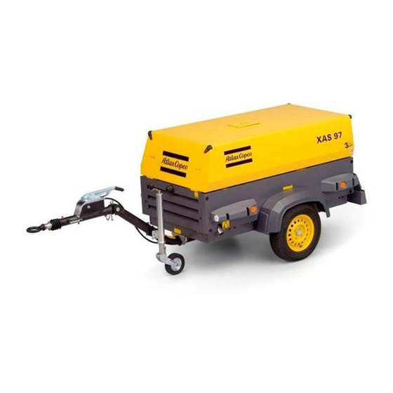
XAS 97 DD — XAS 185 DD7
Engine Deutz D2011L03
Engine Deutz F3M2011
Related Manuals for Atlas Copco XAS 97 DD
Summary of Contents for Atlas Copco XAS 97 DD
-
Page 1
Atlas Copco Instruction Manual Instruction Manual for Portable Compressors English Engine Deutz D2011L03 XAS 97 DD — XAS 185 DD7 Engine Deutz F3M2011… -
Page 3
Instruction Manual for Portable Compressors XAS 97 DD — XAS 185 DD7 Printed matter N° 9829 3095 00 ATLAS COPCO — PORTABLE AIR DIVISION www.atlascopco.com 11/2008… -
Page 4
The manufacturer does not accept any liability for any damage arising for modifications, additions or conversions made without the manufacturer’s approval in writing. While every effort has been made to ensure that the information in this manual is correct, Atlas Copco does not assume responsibility for possible errors. -
Page 5: Table Of Contents
Preface Table of contents Starting / Stopping ……..32 Before starting……….32 Please read the following instructions carefully before starting to use your compressor. 4.3.1 Starting procedures …….. 32 Safety precautions ……..5 4.3.2 During operation ……..34 Introduction ……….5 It is a solid, safe and reliable machine, built 4.3.3 Stopping procedure ……..
-
Page 6
Adjustments and servicing procedures .. 45 Disposal …………. 63 Adjustment of the continuous 11.1 General …………63 regulating system……..45 11.2 Disposal of materials……..63 Air filter engine/compressor……. 46 Maintenance Log ……..64 6.2.1 Main parts ……….46 6.2.2 Cleaning the dust trap ……46 6.2.3 Replacing the air filter element …. -
Page 7: Safety Precautions
To be read attentively and acted accordingly before towing, lifting, operating, performing maintenance or repairing the compressor. INTRODUCTION The policy of Atlas Copco is to provide the users of It is the responsibility of management to appoint Take necessary steps to keep unauthorized persons…
-
Page 8: General Safety Precautions
GENERAL SAFETY PRECAUTIONS The manufacturer does not accept any liability for any Care shall be taken to avoid damage to safety damage arising from the use of non-original parts and valves other pressure-relief devices, The owner is responsible for maintaining the unit for modifications, additions or conversions made especially to avoid plugging by paint, oil coke or in a safe operating condition.
-
Page 9: Safety During Transport And Installation
13 If the warning light on the ABS module or in the Place the unit on level ground and apply the bends in lifting cables, chains or ropes. vehicle lights up, please contact Atlas Copco. parking brake before disconnecting the unit from Helicopter lifting is not allowed.
-
Page 10
13 Never refill fuel while the unit is running, unless The air line end connected to the outlet valve relatively short times, about the need to wear otherwise stated in the Atlas Copco Instruction must be safeguarded with a safety cable, attached ear protectors, Book (AIB). -
Page 11: Safety During Maintenance And Repair
(check valves) to isolate recommended or approved by Atlas Copco or the pressure systems. In addition, a warning sign machine manufacturer. Ascertain that the bearing a legend such as ”work in progress; do selected lubricants comply with all applicable not open”…
-
Page 12: Tool Applications Safety
15 Protect the engine, alternator, air intake filter, 23 Make sure that oil, solvents and other substances electrical and regulating components, etc., to likely to pollute the environment are properly prevent moisture ingress, e.g. when steam- disposed of. cleaning. 24 Before clearing the unit for use after maintenance 16 When performing any operation involving heat, or overhaul, check that operating pressures, flames or sparks on a machine, the surrounding…
-
Page 13: Specific Safety Precautions
If the set pressure must be altered then use only When batteries are being charged, an explosive correct parts supplied by Atlas Copco and in — the minimum working temperature Tmin in °C gas mixture forms in the cells and might escape (°F),…
-
Page 14: Leading Particulars
Injected oil is used for sealing, cooling and lubricating purposes. Compressor oil system The oil is boosted by air pressure. The system has no The compressors type XAS 97 DD — XAS 185 DD7 oil pump. silenced, single-stage, oil-injected…
-
Page 15
Regulation Frame and axles Data plate The compressor is provided with a continuous The compressor/engine unit is supported by rubber regulating system and a blow-down valve which is buffers in the frame. The standard unit has a none integrated in the unloader assembly. The valve is adjustable towbar with support leg and one of the closed during operation by outlet pressure of the following towing eyes AC, DIN, ball, ITA, GB or… -
Page 16: Main Parts
Main Parts (EP) (OFe) (TB) (AFD) (VI) (AR) (RV) (SV) (FP) (OLG) (DPec) (FCeo) (FCft) (AOV) (DSe) (CP) (FU) (OFce) (FF) (CE) (DPft) (FT) (AF) (VV) — 14 -…
-
Page 17
Reference Name Reference Name Alternator Hood Air Filter OFce Oil Filter (compressor element) Anti-Frost Device (option) Oil Filter (engine) Air Outlet Valves Oil Level Gauge (compressor element) Air Receiver Regulating Valve Coupling Starting Motor Compressor Element Safety Valve Control Panel Towbar Data Plate Vacuum Indicator… -
Page 18: Compressor Regulating System
COMPRESSOR REGULATING SYSTEM OVERVIEW (AF) (VI) (SC) (VV) (RV) (PG) (FR) (SV) (SR) (BOV) (OCce) (UV) (UA) (VH) (OS) (BDV) (CV) (OF) (AR) (SL) (AOV) (CE) (TS) (FP) (DP) (SL) (OLG) (FN) (DP) (DP) — 16 -…
-
Page 19
Reference Name Reference Name Air Filter Pressure Gauge Air Outlet Valves Regulating Valve Air Receiver Safety Cartridge (option) Blow Down Valve Scavenge Line Blow Off Valve Speed Regulator Compressor Element Safety Valve Check Valve Temperature Switch Drain Plug Unloader Assembly Engine Unloader Valve Vent Hole… -
Page 20: Air Flow
AIR FLOW Air drawn through the airfilter (AF) into the compressor element (CE) is compressed. At the element outlet, compressed air and oil pass into the air (AF) receiver/oil separator (AR/OS). The check valve (CV) prevents blow-back of compressed air when the compressor is stopped. In the air receiver/oil separator (AR/OS), most of the oil is removed from the air/oil mixture;…
-
Page 21: Oil System
OIL SYSTEM The lower part of the air receiver (AR) serves as oil tank. Air pressure forces the oil from the air receiver/oil separator (AR/OS) through the oil cooler (OCce) and oil filter (OF) to the compressor element (CE). When the compressor is stopped and / or there is no pressure in the system, the oil stop valve (OSV) prevents the oil from flowing back into the compressor element.
-
Page 22: Continuous Regulating System
CONTINUOUS REGULATING SYSTEM (RV) (SR) (UV) (UA) (VH) (AR) (CE) — 20 -…
-
Page 23
The compressor is provided with a continuous If the air consumption is less than the maximum air regulating system. This system is provided with a output, the regulating valve supplies control air to blow-down valve which is integrated in the unloader unloader valve (UV) to reduce the air output and assembly (UA). -
Page 24: Electric System
ELECTRIC SYSTEM Circuit diagram (standard) (9822 0797 01) The compressor is equipped with a negative earthed system. 12V DC 14« 15« 13« 8« 5« 7« D- D+ 6« 1« Auxiliary 2« 12« 3« Temp General 4« alarm (Lamp- tester) 9´,10´,11´ — 22 -…
-
Page 25
Reference Name Circuit Breaker (10 A) Alternator Battery Temperature Alarm Lamp General Alarm Lamp Starter Solenoid (part of M1) Shut-down Relay Blocking Relay Override Start Relay Start Relay Starter Motor Hourmeter Contact Switch (Off-On- Override-start) Temperature Switch Engine Oil Pressure Switch Engine Lamptest Switch Temperature Switch Compressor Fuel Solenoid Valve… -
Page 26
Circuit diagram cold start (9822 0864 00) 12V DC Auxiliary Temp General alarm (Lamptester) — 24 -… -
Page 27
Reference Name Circuit Breaker (10 A) Alternator Battery Temperature Alarm Lamp General Alarm Lamp Starter Solenoid (part of M1) Starter Motor Hourmeter Glowplug Contact Switch (Off-On- Override-start) Temperature Switch Engine Oil Pressure Switch Engine Lamptest Switch Temperature Switch Compressor Push Button Glowplug Fuel Solenoid Valve Diode Diode… -
Page 28
Operation of the electric circuit in detail Start switch S1 position 2: Engine is running normally: Line 3 on 12V (overwrite function) hourmeter P1 and Oil pressure contact S3 opens, K3 no longer excited. (K2) (K1) fuel solenoid Y1 excited. Thermocontact engine S2 K3 changes over (13-11), engine cuts out because fuel normally closed, oil pressure contact S3 open. -
Page 29: Markings And Information Labels
Start-Stop indication of switch. Compressor loaded. Do not run the compressor with open Electrocution hazard. Runlamp. doors. Atlas Copco mineral compressor oil. Airfilter. Lifting device. Atlas Copco synthetic compressor oil. Compressor temperature too high. Use diesel fuel only. 3.7 bar Atlas Copco mineral engine oil.
-
Page 30: Operating Instructions
Operating instructions PARKING INSTRUCTIONS PARKING, TOWING AND LIFTING INSTRUCTIONS Safety precautions The operator is expected to apply all relevant Safety precautions. Attention Before putting the compressor in to use, check the brake system as described in section Brake shoe adjustment. After the first 100 km travel: Non-adjustable towbar with standard support leg without (A) Parking position of jockey wheel (adjustable towbar)
-
Page 31: Towing Instructions
TOWING INSTRUCTIONS Label on towbar, towing instructions Non-adjustable towbar with standard support leg without Adjustable towbar with jockey wheel and brakes brakes For both non-adjustable — and adjustable towbar, the Before towing the compressor, ensure towbar should be as level as possible and the that the towing equipment of the vehicle compressor and towing eye end in a level position.
-
Page 32: Spillage-Free Instruction
SPILLAGE-FREE INSTRUCTION HEIGHT ADJUSTMENT (with adjustable towbar) • Remove spring pin (1). This compressor is fitted with a leak-proof undercarriage in order to protect the environment. • Release locking nut (2) by hand. Any leaking fluid is collected in case of malfunctions. •…
-
Page 33: Lifting Instructions
LIFTING INSTRUCTIONS ANTI-FROST DEVICE (OPTION) When lifting the compressor, the hoist has to be The anti-frost device consist of a manualy operated placed in such a way that the compressor, which must by-pass valve (1) on the oil cooler to prevent freezing be placed level, will be lifted vertically.
-
Page 34: Starting / Stopping
STARTING / STOPPING STARTING PROCEDURES BEFORE STARTING 1. Before initial start-up, prepare battery for operation if not already done. See section Recharging a battery. 2. With the compressor standing level, check the level of the engine oil. Add oil, if necessary, to the upper mark on dipstick.
-
Page 35
Starting procedure The control panel indicates receiver pressure (PG) accumulated operating hours (P1). Before starting open the air outlet valve(s) (see section Compressor regulating system, AOV) and push circuit breaker button (F1) once (open hood first). Circuit breaker button should now be in position B. -
Page 36: During Operation
DURING OPERATION STOPPING PROCEDURE FAULT SITUATIONS AND PROTECTIVE DEVICES When the engine is running, the air • A fault which occurs with the engine, either: oil outlet valves (ball valves) must always be pressure (too low), oil temperature (too high) or put in a fully opened or fully closed alternator voltage (too low) will always and position.
-
Page 37: Maintenance
For engine maintenance refer to Engine Operation Manual. Maintenance schedule Daily 50 hours after initial Yearly or every start-up 500 hours Service pak XAS 97 DD — XAS 185 DD7 2912 4393 06 Engine oil level Check Compressor oil level Check Fuel level Check/Fill…
-
Page 38
Maintenance schedule Daily 50 hours after initial Yearly or every (continuation of page 35) start-up 500 hours Oil coolers Clean Engine minimum and maximum speeds Check Check Torque of wheel nuts Check Check Brake system (if installed) Check/Adjust Check/Adjust Safety valve Test Door hinges Grease… -
Page 39
(continuation of page 36) Notes 1. More frequently when operating in a dusty environment. Keep the bolts of the housing, the lifting eye, the towbar and the axle securely 2. Replace the element after 1000 running hours or when the pressure drop exceeds 0.8 bar (11.6 psi). tightened. -
Page 40: Lubrication Oils
-5°C (23°F) and -20°C (-4°F) PAROIL S PAROIL 5W40 PAROIL from Atlas Copco is the ONLY oil tested PAROIL releases excess heat efficiently, whilst and approved for use in all engines built into Atlas maintaining excellent bore-polish protection to limit Copco compressors and generators.
-
Page 41: Oil Specifications
OIL SPECIFICATIONS COMPRESSOR OIL Mineral compressor oil PAROIL M Liter US gal Order number Never mix synthetic with mineral oil. 1615 5947 00 Remark: 1615 5948 00 When changing from mineral synthetic oil (or the other way around), barrel 55.2 1615 5949 00 you will need to do an extra rinse: After…
-
Page 42: Oil Level Check
OIL LEVEL CHECK CHECK COMPRESSOR OIL LEVEL Never mix oils of different brands or types. Use only non-toxic oils where there is a risk of inhaling delivered air. CHECK ENGINE OIL LEVEL Also consult the Engine Operation Manual for the oil specifications, viscosity recommendations and oil change intervals.
-
Page 43: Oil And Oil Filter Change
(5). Screw out filler plug (2) and add oil until the pointer of the oil level gauge (4) again registers in the upper In this case, contact Atlas Copco. extremity of the green range. Reinstall and tighten the filler plug.
-
Page 44: Cleaning Coolers
CLEANING COOLERS CLEANING FUEL TANK Steam cleaning in combination with a cleansing agent Observe all relevant environmental and may be applied in order to remove also the dirt safety precautions. sticking to the cooler fins. To avoid damaging the coolers, angle Place an appropriate drain pan under the drainplug between jet and coolers should be (see chapter Main Parts, DPec) of the fuel tank.
-
Page 45: Battery Care
BATTERY CARE ACTIVATING A DRY-CHARGED BATTERY RECHARGING A BATTERY • Take out the battery. Before and after charging a battery, always check the Before handling batteries, read the electrolyte level in each cell; if required, top up with • Battery and electrolyte must be at equal relevant safety precautions and act distilled water only.
-
Page 46: Changing Tyres
When a compressor element is due for overhaul, it specific maintenance measure. needs to be done by Atlas Copco. This guarantees the It guarantees that all necessary parts are replaced at use of genuine parts and correct tools with care and When changing a tyre, please observe that the arrow the same time keeping down time to a minimum.
-
Page 47: Adjustments And Servicing Procedures
Adjustments and servicing procedures ADJUSTMENT OF THE CONTINUOUS REGULATING SYSTEM The working pressure is determined by the tension of the spring in the regulating valve (RV). This tension can be increased to raise the pressure and decreased to lower it by turning the adjusting wheel clockwise and anti-clockwise respectively.
-
Page 48: Air Filter Engine/Compressor
MAIN PARTS CLEANING THE DUST TRAP To remove dust from the dust trap pinch the vacuator The Atlas Copco air filters are specially valve (6) several times. designed for the application. The use of non-genuine air filters may lead to…
-
Page 49: Replacing The Air Filter Element
REPLACING THE AIR FILTER ELEMENT AIR RECEIVER SAFETY VALVE All adjustments or repairs are to be done by an authorized representative of the valve supplier. Following checks must be carried out on the safety valve (2): • a check of the opening of the lifting gear, twice a year.
-
Page 50: Fuel System
FUEL SYSTEM BRAKE ADJUSTMENT Before jacking up the compressor, connect it to a towing vehicle or attach a weight of minimum 50 kg (110 lb) to the towbar. BRAKE SHOE ADJUSTMENT Check the thickness of the brake lining. When the brake lining has been worn to a thickness of 1 mm (0.039 in) or less, the brake shoes have to be replaced.
-
Page 51: Test Procedure Of Brake Cable Adjustment
TEST PROCEDURE OF BRAKE CABLE BRAKE CABLE ADJUSTMENT ADJUSTMENT (3) (2) 2 — 3 teeth Hand brake lever downward — brake not operated 1. Brake cable 4. Main brake cable 2. Lock nut 5. Equalizer 1. Check if the towing eye rod of the overrun brake 3.
-
Page 52: Problem Solving
Problem solving It is assumed that the engine is in good condition and Alternator precautions that there is adequate fuel flow to the filter and 1. Never reverse the polarity of the battery or the injection equipment. alternator. 2. Never break any alternator or battery connections An electrical fault must be traced by an while the engine is running.
-
Page 53
Problem Possible faults Corrective actions 3. Temperature alarm lamp (H1) does not a. Lamp (H1) blown a. Replace lamp. light up when switching (S1) to ”I” b. See fault 1d. b. See 1d. and applying lamp test. 4. Starter motor (S) does not crank a. -
Page 54
Engine does not run at max. speed. d. Check the maximum speed, service the fuel filter. e. Oil separator element (OS) clogged. e. Have element removed and inspected by an Atlas Copco Service representative. 12. Working pressure rises during a. -
Page 55: Available Options
Available options Pressure vessel approval: Tool box: Single ASME Twin Undercarriage: Adjustable towbar with brakes Safety: Wheel chocks Fixed towbar with brakes Safety cartridge Support (without undercarriage) Spark arrestor Simplified bumper Safety chain CE/ASME Towing eyes: Loose ball coupling Hose reel Towbar support: Jockey wheel Inlet shutdown valve…
-
Page 56: Technical Specifications
Technical specifications TORQUE VALUES GENERAL TORQUE VALUES CRITICAL TORQUE VALUES The following tables list the recommended torques applied for general applications Assemblies Torque value (Nm / lbf.ft) at assembly of the compressor. Wheel nuts 80 (59) +10/-0 Bolts, axle/beams 80 (59) +/- 10 For hexagon screws and nuts with strength grade 8.8 Bolts, towbar/axle 80 (59) +/- 10…
-
Page 57: Settings Of Shutdown Switches And Safety Valves
SETTINGS OF SHUTDOWN SWITCHES AND SAFETY VALVES Designation XAS 97 DD — XAS 185 DD7 Engine oil pressure bar(e) 17.4 Engine oil temperature °C 127 — 133 °F 260 — 270 Compressor temperature °C 116 — 120 °F 241 — 248…
-
Page 58: Compressor / Engine Specifications
COMPRESSOR / ENGINE SPECIFICATIONS REFERENCE CONDITIONS Designation XAS 97 DD — XAS 185 DD7 Absolute inlet pressure bar(e) 14.5 Relative air humidity Air inlet temperature °C °F Nominal effective working pressure bar(e) The inlet conditions are specified at the air inlet grating outside the canopy.
-
Page 59: Limitations
LIMITATIONS Designation XAS 97 DD — XAS 185 DD7 Minimum effective receiver pressure bar(e) Maximum effective receiver pressure, compressor bar(e) unloaded Maximum ambient temperature no aftercooler °C at sea level °F with aftercooler °C °F Minimum starting temperature °C °F Minimum starting temperature, with coldstart equipment °C…
-
Page 60: Altitude Unit Performance Curve
ALTITUDE UNIT PERFORMANCE CURVE Max. allowable working pressure as a function altitude and ambient temperature. TEMPERATURE IN °F 5000 16 405 4000 13 124 4.0 bar(e) 58 psi 3000 9 843 5.0 bar(e) 73 psi 6.0 bar(e) 2000 6 562 87 psi 7.0 bar(e) 1000…
-
Page 61: Performance Data
PERFORMANCE DATA At reference conditions, if applicable, and at normal shaft speed, unless otherwise stated. Designation XAS 97 DD — XAS 185 DD7 Engine shaft speed, normal and maximum r/min 2750 Engine shaft speed, compressor unloaded r/min 1850 Free air delivery…
-
Page 62: Design Data
DESIGN DATA Compressor Designation Number of compression stages Engine Designation XAS 97 DD — XAS 185 DD7 Designation XAS 97 DD — XAS 185 DD7 Make Deutz Capacity of oil sump: Type D2011L03 — Initial fill F3M2011 US gal 2.25 Coolant — Refill (max.)
-
Page 63
Unit Unit dimensions Designation XAS 97 DD — XAS 185 DD7 without brakes towbar Capacity of compressor oil fixed adjustable system US gal Length 2827 Net capacity of air receiver 16.7 111.3 US gal Width 1410 1410 Capacity of fuel tank 55.5… -
Page 64: Dataplate
Dataplate Company code Model Unit serial number Working pressure Speed Engine power Manufacturing year — 62 -…
-
Page 65
(for example sand, sawdust) and dispose it according the applicable local disposal Your Atlas Copco compressor consists for the most regulations. Do not drain into the sewage system or part of metallic materials, that can be remelted in surface water. -
Page 66
Maintenance Log Compressor ………………Customer ………………..Serial number………………………………….Service hours Maintenance action Date By initials — 64 -… -
Page 68
www.atlascopco.com…
-
Bookmarks
Quick Links
Registration code
Collection: APC X I
Tab:
38
Printed matter N°
2954 0950 00
01/2004
Instruction Manual
for Portable Compressor
XAS97 Dd
ATLAS COPCO — PORTABLE AIR DIVISION
www.atlascopco.com
Related Manuals for Atlas Copco XAS97 Dd
Summary of Contents for Atlas Copco XAS97 Dd
-
Page 1
Instruction Manual for Portable Compressor XAS97 Dd Registration code Collection: APC X I Tab: Printed matter N° 2954 0950 00 ATLAS COPCO — PORTABLE AIR DIVISION www.atlascopco.com 01/2004… -
Page 2
Copyright 2004, Atlas Copco Airpower n.v., Antwerp, Belgium. Any unauthorized use or copying of the contents or any part thereof is prohibited. This applies in particular to trademarks, model denominations, part numbers and… -
Page 3
Instruction Manual Follow the instructions in this booklet and we guarantee you years of troublefree operation. Please read the following instructions carefully before starting to use your machine. Always keep the manual available near the machine. In all correspondence always mention the compressor type and serial number, shown on the data plate. -
Page 4
XAS97 Dd ONTENTS ONTENTS 4 Maintenance …………….20 6 Problem solving …………..29 Use of service paks ……….. 20 Alternator precautions……….29 Preventive maintenance schedule for the compressor ………… 20 7 Available options …………..32 Lubrication oils …………21 Oil level check …………21 8 Technical specifications ………… -
Page 5
To be read attentively and acted accordingly before towing, lifting, operating, performing maintenance or repairing the compressor NTRODUCTION The policy of Atlas Copco is to provide the users of their equipment with The manufacturer does not accept any liability for any damage arising from safe, reliable and efficient products. -
Page 6
If required, a lifting beam shall be applied between hoist and load. Atlas Copco Instruction Book (AIB). Keep fuel away from hot parts such as air outlet pipes or the engine exhaust. Do not smoke when fuelling. -
Page 7
16 Stationary housing guards are provided on all rotating or reciprocating parts not otherwise protected and which may be hazardous to personnel. Parts shall only be replaced by genuine Atlas Copco replacement parts. Machinery shall never be put into operation, when such guards have been All maintenance work, other than routine attention, shall only be removed, before the guards are securely reinstalled. -
Page 8
XAS97 Dd PECIFIC SAFETY PRECAUTIONS 18 When repair has been completed, the machine shall be barred over at least one revolution for reciprocating machines, several revolutions for rotary ones to ensure that there is no mechanical interference within the Batteries machine or driver. -
Page 9
AC, DIN, ball, ITA, GB, NATO (for options see chapter 7). The XAS97 Dd is a silenced, single-stage, oil-injected screw The braking system consists of an integrated parking brake and compressor, built for a nominal effective working pressure of 7 bar. -
Page 10
Danger, heat flat. Service every 24 hours. Warning! Electrocution hazard. Part under pressure. Atlas Copco mineral compressor oil. Do not stand on outlet valves. Atlas Copco synthetic compressor oil. Start-Stop indication of switch. Atlas Copco mineral engine oil. Do not run the motor with open doors. -
Page 11
Instruction Manual ARTS Fig. 2.2 Main parts of XAS97 Dd with some options Alternator Engine Oil Level Dipstick Jockey wheel Air Filter Engine Oil Filter (compressor element) Air outlet valves Exhaust Pipe Oil Filter (engine) Air Receiver Oil Level Gauge (compressor element) -
Page 12
XAS97 Dd OMPRESSOR EGULATING YSTEM Fig. 2.3 Air Filter Engine Oil Level Gauge Temperature Switch Air Receiver Oil Separator Unloader Assembly Air Outlet Valves Filler Plug Pressure Gauge Unloader Valve Blow Down Valve Flow Restrictor Regulating Valve Vent Hole Coupling… -
Page 13
Instruction Manual IL SYSTEM ONTINUOUS REGULATING SYSTEM 2.3) 2.3) The system comprises: The system comprises: AR/OS Air receiver/oil separator Regulating valve Oil cooler Unloader assembly Oil filter Speed regulator The lower part of the air receiver (AR) serves as oil tank. The compressor is provided with a continuous regulating system. -
Page 14
Oil Pressure Switch Engine Starter Solenoid (part of M1) Lamptest Switch Shut-down Relay Temperature Switch Compressor Blocking Relay Fuel Solenoid Valve Override Start Relay Diode Start Relay Diode For location of relais K1, K2, K3, K4, see Atlas Copco Spare Parts List (ASL). -
Page 15
Instruction Manual 2.8.2 D ESCRIPTION Operation of the electric circuit in detail Start button S1 position 1: Engine is running normally: Line 2 on 12V contact K3 closed (13-11), lamp H2 is on. K4 Oil pressure contact S3 opens, K3 no longer excited. K3 changes excites contact K4 (18-15). -
Page 16
XAS97 Dd OPERATING INSTRUCTIONS ARKING TOWING AND LIFTING INSTRUCTIONS When parking a compressor, secure support leg (1) or jockey wheel (2) to support the compressor in a level position. Be sure that the jockey wheel (2) is blocked by the blocking pin (6). -
Page 17
Instruction Manual 3.1.2 T 3.1.3 H OWING INSTRUCTIONS EIGHT ADJUSTMENT WITH ADJUSTABLE TOWBAR Before towing the compressor, ensure that the towing Before towing the compressor, make sure that the joints equipment of the vehicle matches the towing eye or ball of the towbar are secured with maximum strength connector, and ensure that the hood is closed and locked without damaging the towbar. -
Page 18
XAS97 Dd 3.1.4 L IFTING INSTRUCTIONS EFORE STARTING 1. Before initial start-up, prepare battery for operation if not already done. See section 4.8. 2. With the compressor standing level, check the level of the engine oil. Add oil, if necessary, to the upper mark on dipstick. Consult the Engine Operation Manual for the type and viscosity grade of the engine oil. -
Page 19
Instruction Manual TARTING TOPPING Without cold start Hourmeter Circuit breaker button Working pressure gauge Temperature alarm lamp (red) General alarm lamp (red) Contact switch Lamp test With cold start (option) Cold start button Fig. 3.10 Control panel Fault situations and protective devices: Before starting make sure, the electrical circuit is not interrupted by the circuit breaker (F1), located at the bottom of the control panel –… -
Page 20
When servicing, replace all disengaged packings, e.g. gaskets, O-rings, washers. Order Service Paks at your local Atlas Copco dealer. For engine maintenance refer to Engine Operation Manual. The maintenance schedule has to be seen as a guideline for units operating in a dusty environment typical to compressor applications. -
Page 21
Operation Manual and top up with oil if necessary. If you want to use another brand of oil, consult the engine instruction manual. It is strongly recommended to use Atlas Copco branded lubrication oils for the compressor. If you want to use 4.4.2 C HECK COMPRESSOR OIL LEVEL another brands of oil, consult Atlas Copco. -
Page 22
The prescribed interval (see section 4.2) is based on an oil temperature of up to 100 °C and normal operating conditions. When operating in high ambient temperatures, in very dusty or high humidity conditions, it is recommended to change the oil more frequently. In this case, contact Atlas Copco. -
Page 23
Instruction Manual LEANING COOLERS LEANING FUEL TANK Observe all relevant environmental and safety precautions. Place an appropriate drain pan under the drainplug (Fig. 2.2, DP of the fuel tank. Remove the drain plug. Lift the towbar (Fig. 2.2, TB) and tilt the compressor approx. 15° to remove all fuel, dirt and water. -
Page 24
When The order number of the Service Paks are listed in the Atlas Copco charging batteries, each cell must be open, i.e. plugs and/or cover Parts List (ASL). -
Page 25
Instruction Manual ADJUSTMENTS AND SERVICING PROCEDURES DJUSTMENT OF THE CONTINUOUS REGULATING SYSTEM Fig. 5.1 The working pressure is determined by the tension of the spring in the regulating valve (RV). This tension can be increased to raise the pressure and decreased to lower it by turning the adjusting wheel clockwise and anti-clockwise respectively. -
Page 26
5.2.2 R ECOMMENDATIONS IR RECEIVER The Atlas Copco air filters are specially designed for The air receiver is tested according to official standards. Regularly the application. The use of non-genuine air filters may have inspections carried out in conformity with local regulations. -
Page 27
Instruction Manual 5.6.1 B UEL SYSTEM RAKE SHOE ADJUSTMENT Check the thickness of the brake lining. Remove both black plastic plugs (5), one on each wheel. When the brake lining has been worn to a thickness of 1 mm or less, the brake shoes have to be replaced. After inspection and/or replacement re-insert both plugs. -
Page 28
XAS97 Dd 5.6.2 T 5.6.3 B EST PROCEDURE OF BRAKE CABLE RAKE CABLE ADJUSTMENT ADJUSTMENT 1. Check if the towing eye rod of the overrun brake mechanism is in the outmost position. 2. Check if the adjustable towbar (= option) is in the actual towing position. -
Page 29
If it’s not possible to solve the problem with this 4. Never operate the engine without the main or voltage sensing problem solving table, please consult Atlas Copco. cables connected in the circuit. Problem… -
Page 30
Speed regulation cable maladjusted; see section 5.1. d. Engine does not run at max. speed. d. Check the maximum speed, service the fuel filter. e. Oil separator element (OS) clogged. e. Have element removed and inspected by an Atlas Copco Service representative. -
Page 31
15. Air and oil mist expelled from a. Unloader valve (UV) defective. a. Repair valve. air filter after stopping. b. Wrong oil type (without foam-retarding additives). b. Consult Atlas Copco. 16. Compressor overheating. a. Insufficient compressor cooling. a. Relocate compressor. b. Oil cooler (OC) clogged externally. -
Page 32
XAS97 Dd AVAILABLE OPTIONS The XAS97 Dd can be delivered with following options: Pressure vessel approval: ASME Undercarriage: Adjustable with brakes Adjustable without brakes Fixed with brakes Fixed without brakes Support (without undercarriage) Towing eyes: Atlas Copco Ball Italian GB 50 mm… -
Page 33
Instruction Manual TECHNICAL SPECIFICATIONS OMPRESSOR ENGINE SPECIFICATIONS ORQUE VALUES Compressor type Designation Unit 8.1.1 F OR GENERAL APPLICATIONS Reference conditions The following tables list the recommended torques applied for 1. Absolute inlet pressure general applications at assembly of the compressor. 2. -
Page 34
XAS97 Dd ONVERSION LIST OF UNITS INTO RITISH Design data Compressor UNITS 1. Number of compression stages 1 bar 14.504 psi 0.035 oz Engine 1 kg 2.205 lb 1. Make 1 km/h 0.621 mile/h 2. Type F3M2011 1 kW 1.341 hp (UK and US) 3. -
Page 36
Instruction Manual for Portable Compressor XAS97 Dd…
Atlas Copco
Instruction Manual
www.atlascopco.com
Instruction Manual for Portable Compressors
English
XAS 97 DD — XAS 185 DD7
Engine Deutz D2011L03
Engine Deutz F3M2011
Instruction Manual for Portable Compressors
XAS 97 DD — XAS 185 DD7
Printed matter N°
9829 3095 00
11/2008
ATLAS COPCO — PORTABLE AIR DIVISION www.atlascopco.com
Warranty and Liability Limitation
Use only authorized parts.
Any damage or malfunction caused by the use of unauthorized parts is not covered by Warranty or Product
Liability.
The manufacturer does not accept any liability for any damage arising for modifications, additions or conversions made without the manufacturer’s approval in writing.
While every effort has been made to ensure that the information in this manual is correct, Atlas Copco does not assume responsibility for possible errors.
Copyright 2008, Atlas Copco Airpower n.v., Antwerp, Belgium.
Any unauthorized use or copying of the contents or any part thereof is prohibited.
This applies in particular to trademarks, model denominations, part numbers and drawings.
— 2 —
Preface
Please read the following instructions carefully before starting to use your compressor.
It is a solid, safe and reliable machine, built according to the latest technology. Follow the instructions in this booklet and we guarantee you years of troublefree operation.
Always keep the manual available near the machine.
In all correspondence always mention the compressor type and serial number, shown on the data plate.
The company reserves the right to make changes without prior notice.
Table of contents
1
Safety precautions ……………………………….. 5
1.1
Introduction ………………………………………….. 5
1.2
General safety precautions ……………………… 6
1.3
Safety during transport and installation ……. 7
1.4
Safety during use and operation ………………. 7
1.5
Safety during maintenance and repair………. 9
1.6
Tool applications safety ……………………….. 10
1.7
Specific safety precautions……………………. 11
2
Leading particulars ……………………………. 12
2.1
Description of safety pictograms used in this manual………………………………. 12
2.2
General description ……………………………… 12
3
Main Parts…………………………………………. 14
3.1
Compressor regulating system ………………. 16
3.1.1
3.1.2
3.1.3
Overview………………………………………… 16
Air flow ………………………………………….. 18
Oil system ………………………………………. 19
3.1.4
Continuous regulating system……………. 20
3.2
Electric system ……………………………………. 22
3.3
Markings and information labels …………… 27
4
Operating instructions ……………………….. 28
4.1
Parking, towing and lifting instructions ….. 28
4.1.1
Parking instructions …………………………. 28
4.1.2
4.1.3
Towing instructions …………………………. 29
Spillage-Free Instruction…………………… 30
4.1.4
4.1.5
4.1.6
Height adjustment ……………………………. 30
Lifting instructions…………………………… 31
Anti-Frost Device (option)………………… 31
4.2
Starting / Stopping ………………………………. 32
4.3
Before starting…………………………………….. 32
4.3.1
Starting procedures ………………………….. 32
4.3.2
4.3.3
4.3.4
During operation ……………………………… 34
Stopping procedure ………………………….. 34
Fault situations and protective devices .. 34
5
Maintenance ……………………………………… 35
5.1
Use of service paks ……………………………… 35
5.2
Preventive maintenance schedule for the compressor……………………………….. 35
5.3
Lubrication oils …………………………………… 38
5.4
Oil specifications…………………………………. 39
5.4.1
Compressor oil………………………………… 39
5.5
Oil level check ……………………………………. 40
5.5.1
Check engine oil level ……………………… 40
5.5.2
Check compressor oil level……………….. 40
5.6
Oil and oil filter change ……………………….. 41
5.6.1
Engine oil and oil filter change………….. 41
5.6.2
Compressor oil and oil filter change…… 41
5.7
Cleaning coolers………………………………….. 42
5.8
Cleaning fuel tank ……………………………….. 42
5.9
Battery care ………………………………………… 43
5.9.1
Electrolyte………………………………………. 43
5.9.2
5.9.3
5.9.4
Activating a dry-charged battery ……….. 43
Recharging a battery ………………………… 43
Battery maintenance ………………………… 43
5.10
Changing tyres ……………………………………. 44
5.11
Storage ………………………………………………. 44
5.12
Service paks ……………………………………….. 44
5.13
Service kits…………………………………………. 44
5.14
Compressor element overhaul……………….. 44
5.15
Liability……………………………………………… 44
— 3 —
7
8
6
Adjustments and servicing procedures .. 45
6.1
Adjustment of the continuous regulating system…………………………………. 45
6.2
Air filter engine/compressor………………….. 46
6.2.1
Main parts ………………………………………. 46
6.2.2
6.2.3
Cleaning the dust trap ………………………. 46
Replacing the air filter element ………….. 47
6.3
Air receiver…………………………………………. 47
6.4
Safety valve ………………………………………… 47
6.5
Fuel system…………………………………………. 48
6.6
Brake adjustment …………………………………. 48
6.6.1
6.6.2
Brake shoe adjustment ……………………… 48
Test procedure of brake cable adjustment ………………………………………. 49
6.6.3
Brake cable adjustment …………………….. 49
Problem solving …………………………………. 50
Available options ……………………………….. 53
9
Technical specifications ……………………… 54
9.1
Torque values ……………………………………… 54
9.1.1
General torque values……………………….. 54
9.1.2
Critical torque values ……………………….. 54
9.2
Settings of shutdown switches and safety valves …………………………………. 55
9.3
Compressor / engine specifications ………… 56
9.3.1
Reference conditions………………………… 56
9.3.2
9.3.3
Limitations ……………………………………… 57
Altitude unit performance curve ………… 58
9.3.4
9.3.5
Performance data……………………………… 59
Design data……………………………………… 60
10
Dataplate …………………………………………… 62
11
Disposal …………………………………………….. 63
11.1
General ………………………………………………. 63
11.2
Disposal of materials……………………………. 63
12
Maintenance Log ……………………………….. 64
— 4 —
Safety precautions
To be read attentively and acted accordingly before towing, lifting, operating, performing maintenance or repairing the compressor.
INTRODUCTION
The policy of Atlas Copco is to provide the users of their equipment with safe, reliable and efficient products. Factors taken into account are among others:
the intended and predictable future use of the products, and the environments in which they are expected to operate,
applicable rules, codes and regulations,
the expected useful product life, assuming proper service and maintenance,
providing the manual with up-to-date information.
Before handling any product, take time to read the relevant instruction manual. Besides giving detailed operating instructions, it also gives specific information about safety, preventive maintenance, etc.
Keep the manual always at the unit location, easy accessible to the operating personnel.
See also the safety precautions of the engine and possible other equipment, which are separately sent along or are mentioned on the equipment or parts of the unit.
These safety precautions are general and some statements will therefore not always apply to a particular unit.
Only people that have the right skills should be allowed to operate, adjust, perform maintenance or repair on Atlas Copco equipment.
It is the responsibility of management to appoint operators with the appropriate training and skill for each category of job.
Skill level 1: Operator
An operator is trained in all aspects of operating the unit with the push-buttons, and is trained to know the safety aspects.
Skill level 2: Mechanical technician
A mechanical technician is trained to operate the unit the same as the operator. In addition, the mechanical technician is also trained to perform maintenance and repair, as described in the instruction manual, and is allowed to change settings of the control and safety system. A mechanical technician does not work on live electrical components.
Skill level 3: Electrical technician
An electrical technician is trained and has the same qualifications as both the operator and the mechanical technician. In addition, the electrical technician may carry out electrical repairs within the various enclosures of the unit. This includes work on live electrical components.
Skill level 4: Specialist from the manufacturer
This is a skilled specialist sent by the manufacturer or its agent to perform complex repairs or modifications to the equipment.
In general it is recommended that not more than two people operate the unit, more operators could lead to unsafe operating conditions.
Take necessary steps to keep unauthorized persons away from the unit and eliminate all possible sources of danger at the unit.
When handling, operating, overhauling and/or performing maintenance or repair on Atlas Copco equipment, the mechanics are expected to use safe engineering practices and to observe all relevant local safety requirements and ordinances. The following list is a reminder of special safety directives and precautions mainly applicable to Atlas Copco equipment.
These safety precautions apply to machinery processing or consuming air. Processing of any other gas requires additional safety precautions typical to the application and are not included herein.
Neglecting the safety precautions may endanger people as well as environment and machinery:
endanger people due to electrical, mechanical or chemical influences,
endanger the environment due to leakage of oil, solvents or other substances,
endanger the machinery due to function failures.
All responsibility for any damage or injury resulting from neglecting these precautions or by nonobservance of ordinary caution and due care required in handling, operating, maintenance or repair, also if not expressly mentioned in this instruction manual, is disclaimed by Atlas Copco.
— 5 —
The manufacturer does not accept any liability for any damage arising from the use of non-original parts and for modifications, additions or conversions made without the manufacturer’s approval in writing.
If any statement in this manual does not comply with local legislation, the stricter of the two shall be applied.
Statements in these safety precautions should not be interpreted as suggestions, recommendations or inducements that it should be used in violation of any applicable laws or regulations.
GENERAL SAFETY PRECAUTIONS
1 The owner is responsible for maintaining the unit in a safe operating condition. Unit parts and accessories must be replaced if missing or unsuitable for safe operation.
2 The supervisor, or the responsible person, shall at all times make sure that all instructions regarding machinery and equipment operation and maintenance are strictly followed and that the machines with all accessories and safety devices, as well as the consuming devices, are in good repair, free of abnormal wear or abuse, and are not tampered with.
3 Whenever there is an indication or any suspicion that an internal part of a machine is overheated, the machine shall be stopped but no inspection covers shall be opened before sufficient cooling time has elapsed; this to avoid the risk of spontaneous ignition of oil vapour when air is admitted.
4 Normal ratings (pressures, temperatures, speeds, etc.) shall be durably marked.
5 Operate the unit only for the intended purpose and within its rated limits (pressure, temperature, speeds, etc.).
6 The machinery and equipment shall be kept clean, i.e. as free as possible from oil, dust or other deposits.
7 To prevent an increase in working temperature, inspect and clean heat transfer surfaces (cooler fins, intercoolers, water jackets, etc.) regularly.
See the Preventive maintenance schedule for
the compressor.
8 All regulating and safety devices shall be maintained with due care to ensure that they function properly. They may not be put out of action.
9 Care shall be taken to avoid damage to safety valves and other pressure-relief devices, especially to avoid plugging by paint, oil coke or dirt accumulation, which could interfere with the functioning of the device.
10 Pressure and temperature gauges shall be checked regularly with regard to their accuracy. They shall be replaced whenever outside acceptable tolerances.
11 Safety devices shall be tested as described in the maintenance schedule of the instruction manual to determine that they are in good operating
condition. See the Preventive maintenance
schedule for the compressor.
12 Mind the markings and information labels on the unit.
13 In the event the safety labels are damaged or destroyed, they must be replaced to ensure operator safety.
14 Keep the work area neet. Lack of order will increase the risk of accidents.
15 When working on the unit, wear safety clothing.
Depending on the kind of activities these are: safety glasses, ear protection, safety helmet
(including visor), safety gloves, protective clothing, safety shoes. Do not wear the hair long and loose (protect long hair with a hairnet), or wear loose clothing or jewelry.
16 Take precautions against fire. Handle fuel, oil and anti-freeze with care because they are inflammable substances. Do not smoke or approach with naked flame when handling such substances. Keep a fire-extinguisher in the vicinity.
— 6 —
SAFETY DURING TRANSPORT AND
INSTALLATION
When towing, lifting or transporting the compressor in any way, the battery switch must always be in the
“OFF” position!
To lift a unit, all loose or pivoting parts, e.g. doors and towbar, shall first be securely fastened.
Do not attach cables, chains or ropes directly to the lifting eye; apply a crane hook or lifting shackle meeting local safety regulations. Never allow sharp bends in lifting cables, chains or ropes.
Helicopter lifting is not allowed.
It is strictly forbidden to dwell or stay in the risk zone under a lifted load. Never lift the unit over people or residential areas. Lifting acceleration and retardation shall be kept within safe limits.
1 Before towing the unit:
ascertain that the pressure vessel(s) is (are) depressurized,
check the towbar, the brake system and the towing eye. Also check the coupling of the towing vehicle,
check the towing and brake capability of the towing vehicle,
check that the towbar, jockey wheel or stand leg is safely locked in the raised position,
ascertain that the towing eye can swivel freely on the hook,
check that the wheels are secure and that the tyres are in good condition and inflated correctly,
connect the signalisation cable, check all lights and connect the pneumatic brake couplers,
attach the safety break-away cable or safety chain to the towing vehicle,
remove wheel chocks, if applied, and disengage the parking brake.
2 To tow a unit use a towing vehicle of ample capacity. Refer to the documentation of the towing vehicle.
3 If the unit is to be backed up by the towing vehicle, disengage the overrun brake mechanism
(if it is not an automatic mechanism).
4 Never exceed the maximum towing speed of the unit (mind the local regulations).
5 Place the unit on level ground and apply the parking brake before disconnecting the unit from the towing vehicle. Unclip the safety break-away cable or safety chain. If the unit has no parking brake or jockey wheel, immobilize the unit by placing chocks in front of and/or behind the wheels. When the towbar can be positioned vertically, the locking device must be applied and kept in good order.
6 To lift heavy parts, a hoist of ample capacity, tested and approved according to local safety regulations, shall be used.
7 Lifting hooks, eyes, shackles, etc., shall never be bent and shall only have stress in line with their design load axis. The capacity of a lifting device diminishes when the lifting force is applied at an angle to its load axis.
8 For maximum safety and efficiency of the lifting apparatus all lifting members shall be applied as near to perpendicular as possible. If required, a lifting beam shall be applied between hoist and load.
9 Never leave a load hanging on a hoist.
10 A hoist has to be installed in such a way that the object will be lifted perpendicular. If that is not possible, the necessary precautions must be taken to prevent load-swinging, e.g. by using two hoists, each at approximately the same angle not exceeding 30° from the vertical.
11 Locate the unit away from walls. Take all precautions to ensure that hot air exhausted from the engine and driven machine cooling systems cannot be recirculated. If such hot air is taken in by the engine or driven machine cooling fan, this may cause overheating of the unit; if taken in for combustion, the engine power will be reduced.
12 Before moving the compressor, switch it off.
13 If the warning light on the ABS module or in the vehicle lights up, please contact Atlas Copco.
SAFETY DURING USE AND OPERATION
1 When the unit has to operate in a fire-hazardous environment, each engine exhaust has to be provided with a spark arrestor to trap incendiary sparks.
2 The exhaust contains carbon monoxide which is a lethal gas. When the unit is used in a confined space, conduct the engine exhaust to the outside atmosphere by a pipe of sufficient diameter; do this in such a way that no extra back pressure is created for the engine. If necessary, install an extractor. Observe any existing local regulations.
Make sure that the unit has sufficient air intake for operation. If necessary, install extra air intake ducts.
3 When operating in a dust-laden atmosphere, place the unit so that dust is not carried towards it by the wind. Operation in clean surroundings considerably extends the intervals for cleaning the air intake filters and the cores of the coolers.
— 7 —
4 Close the compressor air outlet valve before connecting or disconnecting a hose. Ascertain that a hose is fully depressurized before disconnecting it. Before blowing compressed air through a hose or air line, ensure that the open end is held securely, so that it cannot whip and cause injury.
5 The air line end connected to the outlet valve must be safeguarded with a safety cable, attached next to the valve.
6 No external force may be exerted on the air outlet valves, e.g. by pulling on hoses or by installing auxiliary equipment directly to a valve, e.g. a water separator, a lubricator, etc. Do not step on the air outlet valves.
7 Never move a unit when external lines or hoses are connected to the outlet valves, to avoid damage to valves, manifold and hoses.
8 Do not use compressed air from any type of compressor, without taking extra measures, for breathing purposes as this may result in injury or death. For breathing air quality, the compressed air must be adequately purified according to local legislation and standards. Breathing air must always be supplied at stable, suitable pressure.
9 Distribution pipework and air hoses must be of correct diameter and suitable for the working pressure. Never use frayed, damaged or deteriorated hoses. Replace hoses and flexibles before the lifetime expires. Use only the correct type and size of hose end fittings and connections.
10 If the compressor is to be used for sand-blasting or will be connected to a common compressed-air system, fit an appropriate non-return valve (check valve) between compressor outlet and the connected sand-blasting or compressed-air system. Observe the right mounting position/ direction.
11 Before removing the oil filler plug, ensure that the pressure is released by opening an air outlet valve.
12 Never remove a filler cap of the cooling water system of a hot engine. Wait until the engine has sufficiently cooled down.
13 Never refill fuel while the unit is running, unless otherwise stated in the Atlas Copco Instruction
Book (AIB). Keep fuel away from hot parts such as air outlet pipes or the engine exhaust. Do not smoke when fuelling. When fuelling from an automatic pump, an earthing cable should be connected to the unit to discharge static electricity. Never spill nor leave oil, fuel, coolant or cleansing agent in or around the unit.
14 All doors shall be shut during operation so as not to disturb the cooling air flow inside the bodywork and/or render the silencing less effective. A door should be kept open for a short period only e.g. for inspection or adjustment.
15 Periodically carry out maintenance works according to the maintenance schedule.
16 Stationary housing guards are provided on all rotating or reciprocating parts not otherwise protected and which may be hazardous to personnel. Machinery shall never be put into operation, when such guards have been removed, before the guards are securely reinstalled.
17 Noise, even at reasonable levels, can cause irritation and disturbance which, over a long period of time, may cause severe injuries to the nervous system of human beings. When the sound pressure level, at any point where personnel normally has to attend, is:
below 70 dB(A): no action needs to be taken,
above 70 dB(A): noise-protective devices should be provided for people continuously being present in the room,
below 85 dB(A): no action needs to be taken for occasional visitors staying a limited time only,
above 85 dB(A): room to be classified as a noise-hazardous area and an obvious warning shall be placed permanently at each entrance to alert people entering the room, for even relatively short times, about the need to wear ear protectors,
above 95 dB(A): the warning(s) at the entrance(s) shall be completed with the recommendation that also occasional visitors shall wear ear protectors,
above 105 dB(A): special ear protectors that are adequate for this noise level and the spectral composition of the noise shall be provided and a special warning to that effect shall be placed at each entrance.
18 The unit has parts, which may be accidentally touched by personnel, of which the temperature can be in exess of 80 °C (176 °F). The insulation or safety guard, protecting these parts shall not be removed before the parts have cooled down to room temperature.
19 Never operate the unit in surroundings where there is a possibility of taking in flammable or toxic fumes.
20 If the working process produces fumes, dust or vibration hazards, etc., take the necessary steps to eliminate the risk of personnel injury.
21 When using compressed air or inert gas to clean down equipment, do so with caution and use the appropriate protection, at least safety glasses, for the operator as well as for any bystander. Do not apply compressed air or inert gas to your skin or direct an air or gas stream at people. Never use it to clean dirt from your clothes.
— 8 —
22 When washing parts in or with a cleaning solvent, provide the required ventilation and use appropriate protection such as a breathing filter, safety glasses, rubber apron and gloves, etc.
23 Safety shoes should be compulsory in any workshop and if there is a risk, however small, of falling objects, wearing of a safety helmet should be included.
24 If there is a risk of inhaling hazardous gases, fumes or dust, the respiratory organs must be protected and depending on the nature of the hazard, so must the eyes and skin.
25 Remember that where there is visible dust, the finer, invisible particles will almost certainly be present too; but the fact that no dust can be seen is not a reliable indication that dangerous, invisible dust is not present in the air.
26 Never operate the unit at pressures or speeds below or in excess of its limits as indicated in the technical specifications.
27 Do not use aerosol types of starting aids such as ether. Such use could result in an explosion and personal injury.
SAFETY DURING MAINTENANCE AND
REPAIR
Maintenance, overhaul and repair work shall only be carried out by adequately trained personnel; if required, under supervision of someone qualified for the job.
1 Use only the correct tools for maintenance and repair work, and only tools which are in good condition.
2 Parts shall only be replaced by genuine Atlas
Copco replacement parts.
3 All maintenance work, other than routine attention, shall only be undertaken when the unit is stopped. Steps shall be taken to prevent inadvertent starting. In addition, a warning sign bearing a legend such as ”work in progress; do not start” shall be attached to the starting equipment. On engine-driven units the battery shall be disconnected and removed or the terminals covered by insulating caps. On electrically driven units the main switch shall be locked in open position and the fuses shall be taken out. A warning sign bearing a legend such as ”work in progress; do not supply voltage” shall be attached to the fuse box or main switch.
4 Before dismantling any pressurized component, the compressor or equipment shall be effectively isolated from all sources of pressure and the entire system shall be relieved of pressure. Do not rely on non-return valves (check valves) to isolate pressure systems. In addition, a warning sign bearing a legend such as ”work in progress; do not open” shall be attached to each of the outlet valves.
5 Prior to stripping an engine or other machine or undertaking major overhaul on it, prevent all movable parts from rolling over or moving.
6 Make sure that no tools, loose parts or rags are left in or on the machine. Never leave rags or loose clothing near the engine air intake.
7 Never use flammable solvents for cleaning (firerisk).
8 Take safety precautions against toxic vapours of cleaning liquids.
9 Never use machine parts as a climbing aid.
10 Observe scrupulous cleanliness during maintenance and repair. Keep away dirt, cover the parts and exposed openings with a clean cloth, paper or tape.
11 Never weld on or perform any operation involving heat near the fuel or oil systems. Fuel and oil tanks must be completely purged, e.g. by steam-cleaning, before carrying out such operations. Never weld on, or in any way modify, pressure vessels. Disconnect the alternator cables during arc welding on the unit.
12 Support the towbar and the axle(s) securely if working underneath the unit or when removing a wheel. Do not rely on jacks.
13 Do not remove any of, or tamper with, the sounddamping material. Keep the material free of dirt and liquids such as fuel, oil and cleansing agents.
If any sound-damping material is damaged, replace it to prevent the sound pressure level from increasing.
14 Use only lubricating oils and greases recommended or approved by Atlas Copco or the machine manufacturer. Ascertain that the selected lubricants comply with all applicable safety regulations, especially with regard to explosion or fire-risk and the possibility of decomposition or generation of hazardous gases.
Never mix synthetic with mineral oil.
— 9 —
15 Protect the engine, alternator, air intake filter, electrical and regulating components, etc., to prevent moisture ingress, e.g. when steamcleaning.
16 When performing any operation involving heat, flames or sparks on a machine, the surrounding components shall first be screened with nonflammable material.
17 Never use a light source with open flame for inspecting the interior of a machine.
18 Disconnect –battery-clamp before starting electrical servicing or welding (or turn batteryswitch in “off” position).
19 When repair has been completed, the machine shall be barred over at least one revolution for reciprocating machines, several revolutions for rotary ones to ensure that there is no mechanical interference within the machine or driver. Check the direction of rotation of electric motors when starting up the machine initially and after any alteration to the electrical connection(s) or switch gear, to check that the oil pump and the fan function properly.
20 Maintenance and repair work should be recorded in an operator’s logbook for all machinery.
Frequency and nature of repairs can reveal unsafe conditions.
21 When hot parts have to be handled, e.g. shrink fitting, special heat-resistant gloves shall be used and, if required, other body protection shall be applied.
22 When using cartridge type breathing filter equipment, ascertain that the correct type of cartridge is used and that its useful service life is not surpassed.
23 Make sure that oil, solvents and other substances likely to pollute the environment are properly disposed of.
24 Before clearing the unit for use after maintenance or overhaul, check that operating pressures, temperatures and speeds are correct and that the control and shutdown devices function correctly.
TOOL APPLICATIONS SAFETY
Apply the proper tool for each job. With the knowledge of correct tool use and knowing the limitations of tools, along with some common sense, many accidents can be prevented.
Special service tools are available for specific jobs and should be used when recommended. The use of these tools will save time and prevent damage to parts.
— 10 —
SPECIFIC SAFETY PRECAUTIONS
Batteries
When servicing batteries, always wear protecting clothing and glasses.
1 The electrolyte in batteries is a sulphuric acid solution which is fatal if it hits your eyes, and which can cause burns if it contacts your skin.
Therefore, be careful when handling batteries, e.g. when checking the charge condition.
2 Install a sign prohibiting fire, open flame and smoking at the post where batteries are being charged.
3 When batteries are being charged, an explosive gas mixture forms in the cells and might escape through the vent holes in the plugs. Thus an explosive atmosphere may form around the battery if ventilation is poor, and can remain in and around the battery for several hours after it has been charged. Therefore:
never smoke near batteries being, or having recently been, charged,
never break live circuits at battery terminals, because a spark usually occurs.
4 When connecting an auxiliary battery (AB) in parallel to the unit battery (CB) with booster cables: connect the + pole of AB to the + pole of
CB, then connect the — pole of CB to the mass of the unit. Disconnect in the reverse order.
Pressure vessels
Maintenance/installation requirements:
1 The vessel can be used as pressure vessel or as separator and is designed to hold compressed air for the following application:
pressure vessel for compressor,
medium AIR/OIL, and operates as detailed on the data plate of the vessel:
the maximum working pressure ps in bar (psi),
the maximum working temperature Tmax in
°C (°F),
the minimum working temperature Tmin in °C
(°F),
the capacity of the vessel V in l (US gal, Imp gal, cu.ft).
2 The pressure vessel is only to be used for the applications as specified above and in accordance with the technical specifications. Safety reasons prohibit any other applications.
3 National legislation requirements with respect to re-inspection must be complied with.
4 No welding or heat treatment of any kind is permitted to those vessel walls which are exposed to pressure.
5 The vessel is provided and may only be used with the required safety equipment such as manometer, overpressure control devices, safety valve, etc.
6 Draining of condensate shall be performed daily when vessel is in use.
7. Installation, design and connections should not be changed.
8. Bolts of cover and flanges may not be used for extra fixation.
Safety valves
Operating & Maintenance
Only trained and technically competent personnel should consider overhaul, re-set or performance testing of safety valves.
The safety valve is supplied with either a lead security seal or crimped cover to deter unauthorised access to the pressure regulation device.
Under no circumstances should the set pressure of the safety valve be altered to a different pressure than that stamped on the valve without the permission of the installation designer.
If the set pressure must be altered then use only correct parts supplied by Atlas Copco and in accordance with the instructions available for the valve type.
Safety valves must be frequently tested and regularly maintained.
The set pressure should be periodically checked for accuracy.
When fitted, the compressors should be operated at pressures not less than 75% of the set pressure to ensure free and easy movement of internal parts.
The frequency of tests is influenced by factors such as the severity of the operating environment and aggressiveness of the pressurised medium.
Soft seals and springs should be replaced as part of the maintenance procedure.
Do not paint or coat the installed safety valve (see also
Preventive maintenance schedule for the
compressor).
— 11 —
Leading particulars
DESCRIPTION OF SAFETY PICTOGRAMS
USED IN THIS MANUAL
This symbol draws your attention to dangerous situations. The operation concerned may endanger persons and cause injuries.
This symbol is followed by supplementary information.
GENERAL DESCRIPTION
The compressors type XAS 97 DD — XAS 185 DD7 are silenced, single-stage, oil-injected screw compressors, built for a nominal effective working pressure, ranging from 7 bar (102 psi) up to 10.3 bar
(150 psi) (see chapter Technical specifications).
Engine
The compressor is driven by an oil-cooled diesel engine.
The engine’s power is transmitted to the compressor through a heavy-duty coupling.
Compressor element
The compressor casing houses two screw-type rotors, mounted on ball and roller bearings. The male rotor, driven by the engine, drives the female rotor. The element delivers pulsation-free air.
Injected oil is used for sealing, cooling and lubricating purposes.
Compressor oil system
The oil is boosted by air pressure. The system has no oil pump.
The oil is removed from the air, in the air/oil vessel at first by centrifugal force, secondly through the oil separator element.
The vessel is provided with an oil level indicator.
— 12 —
Regulation
The compressor is provided with a continuous regulating system and a blow-down valve which is integrated in the unloader assembly. The valve is closed during operation by outlet pressure of the compressor element and opens by air receiver pressure when the compressor is stopped.
When the air consumption increases, the air receiver pressure will decrease and vice versa.
This receiver pressure variation is sensed by the regulating valve which, by means of control air to the unloader and engine speed regulator, matches the air output to the air consumption. The air receiver pressure is maintained between the pre-selected working pressure and the corresponding unloading pressure.
Cooling system
Engine and compressor are provided with an oil cooler.
The cooling air is generated by a fan, driven by the engine.
Safety devices
A thermal shut-down switch protects the compressor against overheating. The air receiver is provided with a safety valve.
The engine is equipped with low oil pressure and high oil temperature shut-down switches.
Frame and axles
The compressor/engine unit is supported by rubber buffers in the frame. The standard unit has a none adjustable towbar with support leg and one of the following towing eyes AC, DIN, ball, ITA, GB or
NATO.
As an option the unit can be equipped with an adjustable towbar, a jockey wheel and/or overrun
parking brake (for options see chapter Available
options).
The braking system consists of an integrated parking brake and overrunbrake. When driving backwards the overrunbrake is not engaged automatically.
Bodywork
The bodywork has openings at the shaped front and rear end for the intake and outlet of cooling air and a hood for maintenance and service operations. The bodywork is internally lined with sound-absorbing material.
Lifting eye
A lifting eye is accessible when the small door at the top of the unit is unlocked.
Control panel
The control panel grouping the air pressure gauge, control switch etc., is placed in the center at the rear end.
Data plate
(D)
The compressor is furnished with a data plate (D) showing the product code, the unit number and the
working pressure (see chapter Dataplate).
— 13 —
Main Parts
(H)
(EP)
(OFe)
(A)
(F)
(OLG)
(FP)
(RV)
(AR)
(VI)
(S)
(AFD)
(E)
(SV)
(AOV)
(CP)
(OFce)
(CE)
(C) (FT)
(DPft)
(AF) (VV)
(FF)
(FU)
(D)
(DPec)
(FCeo)
(FCft)
(DSe)
— 14 —
(TB)
FCeo
FCft
FF
FP
FT
FU
CP
D
DPec
DPft
DSe
E
EP
F
Reference Name
A Alternator
AF
AFD
Air Filter
Anti-Frost Device (option)
AOV
AR
C
CE
Air Outlet Valves
Air Receiver
Coupling
Compressor Element
Control Panel
Data Plate
Drain Plug Engine Oil Cooler
Drain Plug Fuel Tank
Engine Oil Level Dipstick
Engine
Exhaust Pipe
Fan
Filler Cap (engine oil)
Filler Cap (fuel tank)
Fuel Filter
Filler Plug (compressor oil)
Fuel Tank
Fuel Pump
RV
S
SV
TB
Reference Name
H Hood
OFce
OFe
OLG
Oil Filter (compressor element)
Oil Filter (engine)
Oil Level Gauge (compressor element)
VI
VV
Regulating Valve
Starting Motor
Safety Valve
Towbar
Vacuum Indicator
Vacuator Valve
— 15 —
COMPRESSOR REGULATING SYSTEM
OVERVIEW
(AF)
(SC)
(VV)
(VI)
(PG)
(OS)
(AOV)
(AR)
(FN)
(DP)
(RV)
(SL)
(FR)
(SV)
(BOV)
(UV)
(UA)
(VH)
(BDV)
(CV)
(OF)
(FP)
(OLG)
(SL)
(CE)
(DP)
(TS)
(SR)
(E)
(OCce)
(F)
(DP)
— 16 —
DP
E
F
FN
FP
FR
OCce
OF
OLG
OS
Reference Name
AF Air Filter
AOV
AR
Air Outlet Valves
Air Receiver
BDV
BOV
CE
CV
Blow Down Valve
Blow Off Valve
Compressor Element
Check Valve
Drain Plug
Engine
Fan
Flow Nozzle
Filler Plug
Flow Restrictor
Oil Cooler (compressor element)
Oil Filter
Oil Level Gauge
Oil Separator
UA
UV
VH
VI
VV
SL
SR
SV
TS
Reference Name
PG Pressure Gauge
RV
SC
Regulating Valve
Safety Cartridge (option)
Scavenge Line
Speed Regulator
Safety Valve
Temperature Switch
Unloader Assembly
Unloader Valve
Vent Hole
Vacuum Indicator
Vacuator Valve
— 17 —
AIR FLOW
(AF)
(PG)
(OS)
(AR)
(FN)
(BDV)
(CV)
(CE)
(TS)
— 18 —
Air drawn through the airfilter (AF) into the compressor element (CE) is compressed. At the element outlet, compressed air and oil pass into the air receiver/oil separator (AR/OS).
The check valve (CV) prevents blow-back of compressed air when the compressor is stopped. In the air receiver/oil separator (AR/OS), most of the oil is removed from the air/oil mixture; the remaining oil is removed by the separator element.
The oil collects in the receiver and on the bottom of the separator element.
The air leaves the receiver via a flow nozzle (FN) which prevents the receiver pressure from dropping below the minimum working pressure (specified in
section Limitations), even when the air outlet valves
are open. This ensures adequate oil injection and prevents oil consumption.
A temperature switch (TS) and a working pressure gauge (PG) are comprised in the system.
A blow-down valve (BDV) is fitted in the unloader assembly to automatically depressurise the air receiver (AR) when the compressor is stopped.
OIL SYSTEM
(FR)
(OS)
(AR)
(SL)
(OF)
(SL)
(CE)
— 19 —
(OCce)
The lower part of the air receiver (AR) serves as oil tank.
Air pressure forces the oil from the air receiver/oil separator (AR/OS) through the oil cooler (OCce) and oil filter (OF) to the compressor element (CE).
When the compressor is stopped and / or there is no pressure in the system, the oil stop valve (OSV) prevents the oil from flowing back into the compressor element.
The compressor element has an oil gallery in the bottom of its casing. The oil for rotor lubrication, cooling and sealing is injected through holes in the gallery.
Lubrication of the bearings is ensured by oil injected into the bearing housings.
The injected oil, mixed with the compressed air, leaves the compressor element and re-enters the air receiver, where it is separated from the air as
described in section Air flow. The oil that collects in
the bottom of the oil separator element is returned to the system through a scavenging line (SL), which is provided with a flow restrictor (FR).
The oil filter by-pass valve opens when the pressure drop over the filter is above normal because of a clogged filter. The oil then by-passes the filter without being filtered. For this reason, the oil filter must be replaced at regular intervals (see section
Preventive maintenance schedule for the
compressor).
When cold start equipment is installed, a thermostatic valve will bypass the compressor oil (oil will not pass through oil cooler OCce), until the working temperature is reached.
CONTINUOUS REGULATING SYSTEM
(AR)
(RV)
(UV)
(UA)
(VH)
(CE)
(SR)
— 20 —
The compressor is provided with a continuous regulating system. This system is provided with a blow-down valve which is integrated in the unloader assembly (UA). The valve is closed during operation by outlet pressure of the compressor element and opens by air receiver pressure when the compressor is stopped.
When the air consumption increases, the air receiver pressure will decrease and vice versa. This receiver pressure variation is sensed by the regulating valve which, by means of control air to the unloader, matches the air output to the air consumption. The air receiver pressure is maintained between the preselected working pressure and the corresponding unloading pressure.
When starting the compressor, the unloader valve
(UV) is kept open by spring force, the engine runs at maximum speed. The compressor element (CE) takes in air and pressure builds up in the receiver (AR).
The air output is controlled from maximum output
(100%) to no output (0%) by:
1. Speed control of the engine between maximum load speed and unloading speed (the output of a screw compressor is proportional to the rotating speed).
2. Air inlet throttling.
If the air consumption is equal to or exceeds the maximum air output, the engine speed is held at maximum load speed and the unloading valve is fully open.
If the air consumption is less than the maximum air output, the regulating valve supplies control air to unloader valve (UV) to reduce the air output and holds air receiver pressure between the normal working pressure and the corresponding unloading pressure of approx. 1.5 bar (2.2 psi) above the normal working pressure.
When the air consumption is resumed, the unloader valve (UV) gradually opens the air intake and the speed regulator (SR) increases the engine speed.
The construction of the regulating valve (RV) is such that any increase (decrease) of the air receiver pressure above the pre-set valve opening pressure results in a proportional increase (decrease) of the control pressure to the unloading valve and the speed regulator.
Part of the control air is vented to the atmosphere, and any condensate discharged, through the vent holes
(VH).
— 21 —
ELECTRIC SYSTEM
Circuit diagram (standard) (9822 0797 01)
3
2
1
0
S1
The compressor is equipped with a negative earthed system.
12V DC
10A
22
S1
F1
23
5
30
0
1
2
3
31
33
32
3
4
1
2
13
10
K3
11
G2
+
K4
19
6
G1
5«
B+
D- D+
6«
7
17
V1
18
K4
15 16
8
12
3
12
3
K0
12«
P1
27 h
26
35
Auxiliary
34
V2
Y1
3«
4«
12
3
12
3
S2
q
8«
7«
S3
p
13
1«
2«
14
K3
14
12
15
1
4
2
K1
12
10
9´,10´,11´
9 9 9
S5
q
14«
15«
11
9
K2
7
25
H1
29
H2
24
Temp
28
General alarm
K2
8
6
12
20
21
S4
(Lamp-
tester)
12 12
K1
5
3
12
K0
13«
M1
M
— 22 —
S2
S3
S4
S5
Y1
V1
V2
K2
K3
K4
M1
P1
S1
H1
H2
K0
K1
Reference
F1
G1
G2
Name
Circuit Breaker (10 A)
Alternator
Battery
Temperature Alarm Lamp
General Alarm Lamp
Starter Solenoid (part of M1)
Shut-down Relay
Blocking Relay
Override Start Relay
Start Relay
Starter Motor
Hourmeter
Contact Switch (Off-On-
Override-start)
Temperature Switch Engine
Oil Pressure Switch Engine
Lamptest Switch
Temperature Switch Compressor
Fuel Solenoid Valve
Diode
Diode
— 23 —
Circuit diagram cold start (9822 0864 00)
12V DC
S1
10A
F1
5
0
1
2
3
2
3
4
1
2
3
4
G2
1
K5
87
30
G1
B+
D+
D-
17
K4
2
86
85
6
7
V1
P2
12 12
30
K4
87 87a
8
K0
P1
V2
12 12
Auxiliary
12
Y1
12
S2
0
87a
30
13
S3
p
87
30
14
K3
86
85
15
87
87a
30
K1
10
12
K2
86
85
K2
30
87
12
30
87
K3
87a
S5
87a
30
11
87
K0
30
S6
16
H1
Temp
S4
(Lamptester)
12 12
H2
General alarm
K5
86
85
12
K1
86
85
12
M1
M
— 24 —
S6
Y1
V1
V2
S2
S3
S4
S5
P1
P2
S1
H1
H2
K0
M1
Reference
F1
G1
G2
Name
Circuit Breaker (10 A)
Alternator
Battery
Temperature Alarm Lamp
General Alarm Lamp
Starter Solenoid (part of M1)
Starter Motor
Hourmeter
Glowplug
Contact Switch (Off-On-
Override-start)
Temperature Switch Engine
Oil Pressure Switch Engine
Lamptest Switch
Temperature Switch Compressor
Push Button Glowplug
Fuel Solenoid Valve
Diode
Diode
— 25 —
Operation of the electric circuit in detail
(K1)
(K2)
(K3)
(K4)
Start switch S1 position 1:
Line 2 on 12V contact K3 closed (13-11), lamp H2 is on. K4 excites contact K4 (18-15). Thermocontact element S5 normally closed, K1 excites contact K1
(1-4).
Use of lamp test:
Start switch S1 position 1 press lamp test S4, across
K3 and line 9 lamp H1 and relay K2 are excited. After releasing lamp test button S4, lamp H1 remains on, S4 taken over by contact K2.
Start switch S1 position 2:
Line 3 on 12V (overwrite function) hourmeter P1 and fuel solenoid Y1 excited. Thermocontact engine S2 normally closed, oil pressure contact S3 open.
Start switch S1 position 3:
Start relay K0 is excited and starter motor is running, engine builds up oil pressure and oil pressure contact
S3 closes. K3 excited and contact K3 changes over to
(13-10). Relay K2 no longer excited, contact K2 opens, lamp H1 goes out. Alternator also commences supplying voltage and K4 is no longer excited and contact K4 changes over to (18-16). Lamp H2 goes out, one can release start switch S1 and it returns to position 1. Exciting the safety devices occurs no longer across line 3 but across line 2 to line 4 and this way to line 3.
Engine is running normally:
Oil pressure contact S3 opens, K3 no longer excited.
K3 changes over (13-11), engine cuts out because fuel solenoid Y1 no longer excited and lamp H2 goes on simultaneously.
Thermocontact S2 opens, K3 no longer excited. K3 changes over (13-11), engine cuts out because fuel solenoid Y1 no longer excited and lamp H2 goes on simultaneously.
Thermocontact S5 opens, K1 no longer excited.
Contact K1 changes over (4-2). K3 no longer excited.
K3 changes over (13-11), engine cuts out because fuel solenoid Y1 no longer excited and lamp H2 and H1 go on simultaneously. Take-over relay K2 is excited simultaneously with H1 and contact K2 closes (8-6).
Thermocontact S5 cools off and closes, K1 excited again and contact K1 changes over (4-1). However, lamp H1 remains on across line 9 and contact K2 (6-
8).
A fault in the alternator part causes terminal D+ to go to 0V and K4 to be excited. Contact K4 changes over to (18-15), engine cuts out because fuel solenoid Y1 no longer excited and lamp H2 goes on simultaneously.
— 26 —
MARKINGS AND INFORMATION LABELS
Compressor outlet temperature too high.
Compressor outlet temperature.
Compressor outlet pressure.
Danger, outlet gases.
Danger, hot surface.
Electrocution hazard.
Atlas Copco mineral compressor oil.
Atlas Copco synthetic compressor oil.
Atlas Copco mineral engine oil.
Manual.
Read the instruction manual before working on the battery.
Reset fuse.
On / off button.
Manual override switch.
Hours, time.
Prohibition to open air valves without connected hoses.
Compressor loaded.
Runlamp.
Airfilter.
Compressor temperature too high.
Rotation direction.
Inlet.
Outlet.
Compressor oil drain.
Read the instruction manual before starting.
Service every 24 hours.
Warning! Part under pressure.
Do not stand on outlet valves.
Start-Stop indication of switch.
Do not run the compressor with open doors.
Lifting device.
Use diesel fuel only.
3.7 bar
(54 psi)
Tyre pressure.
Sound power level in accordance with
Directive 2000/14/EC (expressed in dB (A)).
Sound power level in accordance with
Directive 2000/14/EC (expressed in dB (A)).
Horizontal towbar position required in case of coupling.
— 27 —
Operating instructions
PARKING, TOWING AND LIFTING
INSTRUCTIONS
Safety precautions
The operator is expected to apply all
relevant Safety precautions.
PARKING INSTRUCTIONS
(2)
(4)
(2)
(4)
(A)
Attention
Before putting the compressor in to use, check the brake system as described in
section Brake shoe adjustment.
After the first 100 km travel:
Check and retighten the wheel nuts and towbar bolts to the specified torque. See
section Compressor / engine specifications.
Check the brake adjustment. See section
Brake shoe adjustment.
(1)
Non-adjustable towbar with standard support leg without brakes
(B)
(A) Parking position of jockey wheel (adjustable towbar)
(B) Rear-end of compressor upwind
(3)
(5)
(4)
(2)
Adjustable towbar with jockey wheel and brakes
When parking a compressor, secure support leg (1) or jockey wheel (2) to support the compressor in a level position. Be sure that the jockey wheel (2) is blocked by the blocking pin (4).
Apply parking brake by pulling parking brake handle
(3) upwards. Place the compressor as level as possible; however, it can be operated temporarily in an out-of-level position not exceeding 15°. If the compressor is parked on sloping ground, immobilize the compressor by placing wheel chocks (available as option) in front of or behind the wheels. Locate the rear-end of the compressor upwind, away from contaminated wind-streams and walls. Avoid recirculation of exhaust air from the engine. This causes overheating and engine power decrease.
— 28 —
TOWING INSTRUCTIONS
(3)
Label on towbar, towing instructions
Before towing the compressor, ensure that the towing equipment of the vehicle matches the towing eye or ball connector, and ensure that the hood is closed and locked properly.
(1)
Non-adjustable towbar with standard support leg without brakes
(4)
(2)
Adjustable towbar with jockey wheel and brakes
For both non-adjustable — and adjustable towbar, the towbar should be as level as possible and the compressor and towing eye end in a level position.
Push the hand brake lever (3) completely downwards and connect breakaway cable (4) to the vehicle.
Secure jockey wheel (2) or support leg (1) in the highest possible position. The jockey wheel is prevented from turning.
Towing position of jockey wheel
— 29 —
SPILLAGE-FREE INSTRUCTION
This compressor is fitted with a leak-proof undercarriage in order to protect the environment.
Any leaking fluid is collected in case of malfunctions.
This fluid can be removed via outlets, normally secured by caps.
Tighten the caps firmly and check for leakages.
Please observe the locally applicable environmental regulations when removing the leaking liquid.
HEIGHT ADJUSTMENT
(with adjustable towbar)
(2)
(1)
• Remove spring pin (1).
• Release locking nut (2) by hand.
• Adjust required height of the towbar.
• Tighten locking nut (2) by hand.
• Fix locking nut (2) with spring pin (1).
Attention:
Before towing the compressor, make sure that the joints of the towbar are secured with maximum strength without damaging the towbar. Be sure that there is no clearance between the teeth of the joints.
• Height adjustment should be undertaken on levelled ground and in coupled condition.
• When readjusting, make sure that the front point of the towbar is horizontal to the coupling point.
• Before starting a trip, ensure that the adjustment shaft is secure, so that the stability and safety is guaranteed while driving. If necessary tighten the locking nut (2).
— 30 —
LIFTING INSTRUCTIONS ANTI-FROST DEVICE (OPTION)
(2)
(1)
When lifting the compressor, the hoist has to be placed in such a way that the compressor, which must be placed level, will be lifted vertically. Keep lifting acceleration and retardation within safe limits.
Preferably use the lifting eye (1) after opening the small door (2).
Lifting acceleration and retardation must be kept within safe limits (max.
2xg).
Helicopter lifting is not allowed.
Lifting is not allowed when the unit is running.
1
The anti-frost device consist of a manualy operated by-pass valve (1) on the oil cooler to prevent freezing of the pneumatic tools at low ambient temperatures
(partial by-pass).
As soon as the ambient temperature drops below
20° C (68° F) it is recommended to open the valve and by-pass the oil cooler. The outlet air temperature will increase with 13 — 16° C (23 — 29° F) and condensation in the air will be reduced.
It is also recommend to use the by-pass valve in case the compressor is used at partial load for a long time.
— 31 —
STARTING / STOPPING
BEFORE STARTING
1. Before initial start-up, prepare battery for operation if not already done. See section
Recharging a battery.
2. With the compressor standing level, check the level of the engine oil. Add oil, if necessary, to the upper mark on dipstick. Also check the engine coolant level. Consult the Engine Operation
Manual for the type of coolant and type and viscosity grade of the engine oil.
3. Check the level of the compressor oil. The pointer of oil level gauge (OLG) should register in the
green range. Add oil if necessary. See section Oil
level check for the oil to be used.
Before removing oil filler plug (FP), ensure that the pressure is released by opening an air outlet valve.
4. Check that the fuel tank contains sufficient fuel.
Top up, if necessary. Consult the Engine
Operation Manual for the type of fuel.
5. In case of start up of the unit, after running out of fuel, pump up the fuel manually with the fuel hand pump before starting.
6. Drain any water and sediment from the fuel filters until clean fuel flows from the drain cock.
7. Drain leaking fluid from the frame.
8. Press vacuator valves (VV) of the air filter to remove dust.
9. Check the air filter vacuum indicators (VI). If the yellow piston reaches the red marked service range, replace the filter element. Reset the indicator by pushing the reset button.
10. Open air outlet valve to allow air flow to the atmosphere.
STARTING PROCEDURES
Reference Name
P1
F1
PG
H1
H2
S1
S4
Hourmeter
P1
Circuit breaker button
Working pressure gauge
PG
Temperature alarm lamp (red)
General alarm lamp (red)
Start switch
Lamp test button
— 32 —
H1 F1 S1
H2 0 1 2 3 S4
Starting procedure
The control panel indicates receiver pressure (PG) and accumulated operating hours (P1).
Before starting open the air outlet valve(s) (see
section Compressor regulating system, AOV) and
push circuit breaker button (F1) once (open hood first). Circuit breaker button should now be in position B.
(F1)
A
B
1. To start, turn start switch S1 clockwise to position
1, lamp H2 (general alarm lamp) will go on.
2. Check correct operation of alarm lamps H1 and
H2 by pushing lamp test button S4. Both alarm lamps (red) should go on.
3. Turn start switch S1 further clockwise into position 3.
The starter motor will set the engine in motion.
The maximum allowed starter time, where the starter motor is running continuously is 20 seconds.
If the engine does not catch, a new attempt can be made after 30 seconds waiting.
The temperature alarm lamp H1 and the general alarm lamp H2 will go out as soon as the engine has been started.
4. The start switch automatically springs back to position 1.
Lamp H1 only will go on when the compressor outlet temperature is too high.
5. Close the air outlet valve(s) (AOV).
The circuit breaker button is a protection against unintended starting of the compressor.
— 33 —
DURING OPERATION
When the engine is running, the air outlet valves (ball valves) must always be put in a fully opened or fully closed position.
The hood must be closed during operation and may be opened for short periods only.
Regularly carry out following checks:
1. That regulating valve (see section Main Parts,
RV) is correctly adjusted, i.e. starts decreasing the engine speed when reaching the preset working pressure in the receiver.
2. Check the air filter vacuum indicators (see section
Main Parts, VI). If the yellow piston reaches the
red marked service range, replace the filter element. Reset the indicators by pushing the reset button.
3. On compressors with aftercooler, check that the automatic drain of the water separator is operative without air leakage.
STOPPING PROCEDURE
3 min
1. Close the air outlet valves (see section
Compressor regulating system, AOV).
2. Run unloaded for 3 minutes.
3. Turn the start switch S1 counterclockwise (CCW) to position 0.
4. Push the circuit breaker button (F1) once (open hood first). Circuit breaker button should now be in position A.
(F1)
FAULT SITUATIONS AND PROTECTIVE
DEVICES
• A fault which occurs with the engine, either: oil pressure (too low), oil temperature (too high) or alternator voltage (too low) will always and immediately cause the engine to cut out and the control lamp H2 will light up. By doing some simple checks, it can be determined what it was that caused the engine to fail: low oil level, clogged-up cooler, slack alternator belt tension or broken belt.
• When the outlet temperature of the element becomes too high, a thermocontact will also switch off the group immediately. Both control lamps H1 and H2 will light up. Both control lamps will remain on until the group has been restarted
(start switch to position 3) or the contact is turned off (start switch to position 0); also when, due to cooling off, the thermocontact has closed again (= memory function).
A
B
— 34 —
Maintenance
USE OF SERVICE PAKS
Service Paks include all genuine parts needed for normal maintenance of both compressor and engine.
Service Paks minimize downtime and keep your maintenance budget low.
Order Service Paks at your local Atlas Copco dealer.
PREVENTIVE MAINTENANCE SCHEDULE FOR THE COMPRESSOR
The schedule contains a summary of the maintenance instructions. Read the respective section before taking maintenance measures.
When servicing, replace all disengaged packings, e.g.
gaskets, O-rings, washers.
For engine maintenance refer to Engine Operation
Manual.
The maintenance schedule has to be seen as a guideline for units operating in a dusty environment typical to compressor applications. Maintenance schedule can be adapted depending on application environment and quality of maintenance.
Maintenance schedule Daily
Service pak XAS 97 DD — XAS 185 DD7
Engine oil level
Compressor oil level
Fuel level
Air filter vacuator valves
Fuel filter water drain
Air intake vacuum indicators
For spillage free, drain water out of frame
General conditions (leaks, damaged parts, loose bolts, trouble in previous operation)
During operation (meters and lamps, noise, colour exhaust fumes)
Electrolyte level and terminals of battery
Tyre pressure
Leaks in air-, oil- or fuel system
(to be continued on page 36)
Check
Check
Check
Check/Fill
Empty
Drain
Check
Check/Drain
Check
50 hours after initial start-up
—
Yearly or every
500 hours
2912 4393 06
Check
Check
Check
Check
Check
Check
— 35 —
Maintenance schedule
(continuation of page 35)
Oil coolers
Engine minimum and maximum speeds
Torque of wheel nuts
Brake system (if installed)
Safety valve
Door hinges
Coupling head and all its moving parts / shaft
Joints of height adjustment adjustable towbar
Shutdown switches
Pressure drop over separator element (2)
Fan V-belt (3)
Fuel tank
Compressor oil
Compressor oil filter
Air filter element (1)
Safety cartridges (1) (option)
Engine oil (3) (4) (5)
Engine oil filter (3)
Fuel filter (3) (6) (8)
Engine inlet and outlet valves (3)
PD / QD filter (option)
(to be continued on page 37)
Daily 50 hours after initial start-up
Check
Check
Check/Adjust
Check
Replace
Yearly or every
500 hours
Clean
Check
Check
Check/Adjust
Test
Grease
Grease
Grease
Check
Replace
Adjust
Clean
Change
Replace
Replace
Replace
Change
Replace
Replace
Adjust (7)
Replace
— 36 —
(continuation of page 36)
Notes
1. More frequently when operating in a dusty environment.
2. Replace the element after 1000 running hours or when the pressure drop exceeds 0.8 bar (11.6 psi).
3. Refer to the Deutz operation manual.
4. 500 hours only valid when using PAROIL SAE 15W40.
5. Also drain engine oil from engine oil cooler (see chapter Main Parts,
DPec = Drain plug engine oil cooler).
6. In case of poor fuel quality, replace fuel filter more frequently.
7. The valves need to be adjusted for the first time before 500 running hours.
8. Option, additional fuel filter: heavy duty filter element 2914 8092 00, to be ordered separately.
Keep the bolts of the housing, the lifting eye, the towbar and the axle securely tightened.
Refer to section Technical specifications
and section Height adjustment for the
torque values.
— 37 —
LUBRICATION OILS
High-quality, mineral, hydraulic or synthesized hydrocarbon oil with rust and oxidation inhibitors and anti-foam and anti-wear properties is recommended. The viscosity grade should correspond to the ambient temperature and
ISO 3448, as follows:
Type of lubricant
between 30°C (86°F) and 40°C (104°F) between 30°C (86°F) and -5°C (23°F) between -5°C (23°F) and -20°C (-4°F)
Compressor**
PAROIL S
PAROIL M
PAROIL S
PAROIL S
Engine*
PAROIL 15W40
PAROIL 15W40
PAROIL 5W40
PAROIL from Atlas Copco is the ONLY oil tested and approved for use in all engines built into Atlas
Copco compressors and generators.
Extensive laboratory and field endurance tests on
Atlas Copco equipment have proven PAROIL to match all lubrication demands in varied conditions. It meets stringent quality control specifications to ensure your equipment will run smoothly and reliably.
The quality lubricant additives in PAROIL allow for extended oil change intervals without any loss in performance or longevity.
PAROIL provides wear protection under extreme conditions. Powerful oxidation resistance, high chemical stability and rust- inhibiting additives help reduce corrosion, even within engines left idle for extended periods.
PAROIL contains high quality anti-oxidants to control deposits, sludge and contaminants that tend to build up under very high temperatures.
PAROIL’s detergent additives keep sludge forming particles in a fine suspension instead of allowing them to clog your filter and accumulate in the valve/rocker cover area.
PAROIL releases excess heat efficiently, whilst maintaining excellent bore-polish protection to limit oil consumption.
PAROIL has an excellent Total Base Number (TBN) retention and more alkalinity to control acid formation.
PAROIL prevents Soot build-up
PAROIL is optimized for the latest low emission
EURO -3 & -2, EPA TIER II & III engines running on low sulphur diesel for lower oil and fuel consumption.
PAROIL 5W40 is a Synthetic ultra high performance diesel engine oil with a high viscosity- index. Atlas
Copco PAROIL 5W40 is designed to provide excellent lubrication from start-up in temperatures as low as -25°C (-13°F).
PAROIL 15W40 is a mineral based high performance diesel engine oil with a high viscosity- index. Atlas
Copco PAROIL 15W40 is designed to provide a high level of performance and protection in ‘standard’ ambient conditions as from -15°C (5°F).
— 38 —
*
If you want to use another brand of oil, consult the engine instruction manual.
**
It is strongly recommended to use Atlas
Copco branded lubrication oils for the compressor. If you want to use another brands of oil, consult Atlas Copco.
OIL SPECIFICATIONS
Never mix synthetic with mineral oil.
Remark:
When changing from mineral to synthetic oil (or the other way around), you will need to do an extra rinse:
After doing the complete change procedure to synthetic oil, run the unit for a few minutes to allow good and complete circulation of the synthetic oil.
Then drain the synthetic oil again and fill again with new synthetic oil. To set correct oil levels, proceed as in normal instruction.
COMPRESSOR OIL
Mineral compressor oil PAROIL M
can can barrel
Liter
5
20
210
Synthetic compressor oil PAROIL S
can can barrel
Liter
5
20
210
Mineral engine oil PAROIL 15W40
can can barrel
Liter
5
20
210
Synthetic engine oil PAROIL 5W40
can can
Liter
5
20
US gal
1.3
5.3
55.2
US gal
1.3
5.3
US gal
1.3
5.3
55.2
US gal
1.3
5.3
55.2
Order number
1615 5947 00
1615 5948 00
1615 5949 00
Order number
1615 5950 01
1615 5951 01
1615 5952 01
Order number
1615 5953 00
1615 5954 00
1615 5955 00
Order number
1604 6060 01
1604 6059 01
— 39 —
OIL LEVEL CHECK
Never mix oils of different brands or types.
Use only non-toxic oils where there is a risk of inhaling delivered air.
CHECK COMPRESSOR OIL LEVEL
(2)
(1)
CHECK ENGINE OIL LEVEL
Also consult the Engine Operation Manual for the oil specifications, viscosity recommendations and oil change intervals.
For intervals, see Preventive maintenance schedule
for the compressor.
Check engine oil level according to the instructions in the Engine Operation Manual and if necessary top up with oil.
(3)
With the unit standing horizontal, check the level of the compressor oil. The pointer of the oil level gauge
(1) must register in the upper extremity of the green range. Add oil if necessary.
Before removing the oil filler plug (2), ensure that the pressure is released by opening an air outlet valve (3).
— 40 —
OIL AND OIL FILTER CHANGE
ENGINE OIL AND OIL FILTER CHANGE
See section Preventive maintenance schedule for
the compressor.
COMPRESSOR OIL AND OIL FILTER CHANGE
(4)
(5)
(2)
(3)
(1)
The quality and the temperature of the oil determine the oil change interval.
The prescribed interval is based on normal operating conditions and an oil temperature of up to 100 °C
(212 °F) (see section Preventive maintenance
schedule for the compressor).
When operating in high ambient temperatures, in very dusty or high humidity conditions, it is recommended to change the oil more frequently.
In this case, contact Atlas Copco.
1. Run the compressor until warm. Close the outlet valve(s) (5) and stop the compressor. Wait until the pressure is released through the automatic blow-down valve. Unscrew the oil filler plug (2) one turn. This uncovers a vent hole, which permits any pressure in the system to escape.
2. Drain the compressor oil by removing all relevant drain plugs. Drain plugs are located at the air receiver (DPar) and compressor element (DPcv,
DPosv). Catch the oil in a drain pan. Screw out the filler plug to speed up draining. After draining, place and tighten the drain plugs.
3. Remove the oil filters (3), e.g. by means of a special tool. Catch the oil in a drain pan.
4. Clean the filter seat on the manifold, taking care that no dirt drops into the system. Oil the gasket of the new filter element. Screw it into place until the gasket contacts its seat, then tighten one half turn only.
5. Fill the air receiver until the pointer of the oil level gauge (4) is in the upper part of the green area. Be sure that no dirt gets into the system. Reinstall and tighten the filler plug.
6. Run the unit at no load for a few minutes to circulate the oil and to evacuate the air trapped in the oil system.
7. Stop the compressor. Let the oil settle for a few minutes. Check that the pressure is released by opening an air outlet valve (5). Screw out filler plug (2) and add oil until the pointer of the oil level gauge (4) again registers in the upper extremity of the green range. Reinstall and tighten the filler plug.
Never add more oil. Overfilling results in oil consumption.
— 41 —
CLEANING COOLERS
(1)
Keep the oil-coolers (1) and (2) clean to maintain the cooling efficiency.
The fan side surface of compressor- and engine oil cooler is accessible by removing the fan cowl upper part.
The opposite surface of compressor- and engine oil cooler is accessible by removing the centre part of the front baffles.
Remove any dirt from the coolers with a fibre brush. Never use a wire brush or metal objects.
(2)
CLEANING FUEL TANK
Steam cleaning in combination with a cleansing agent may be applied in order to remove also the dirt sticking to the cooler fins.
To avoid damaging the coolers, angle between jet and coolers should be approx. 90 °.
Protect the electrical and controlling equipment, air filters, etc. against penetration of moisture.
Close the service door(s).
Never leave spilled liquids such as fuel, oil, water and cleansing agents in or around the compressor.
Observe all relevant environmental and safety precautions.
Place an appropriate drain pan under the drainplug
(see chapter Main Parts, DPec) of the fuel tank.
Remove the drain plug.
Lift the towbar (see chapter Main Parts, TB) and tilt
the compressor approx. 15° to remove all fuel, dirt and water.
Clean the fuel tank and fix the drain plug handtight.
Never leave spilled liquids such as fuel, oil, water and cleansing agents in or around the compressor.
Refill the fuel tank with clean fuel.
— 42 —
BATTERY CARE
Before handling batteries, read the relevant safety precautions and act accordingly.
If the battery is still dry, it must be activated as
described in section Activating a dry-charged
battery.
The battery must be in operation within 2 months from being activated; if not, it needs to be recharged first.
ELECTROLYTE
Read the safety instructions carefully.
Electrolyte in batteries is a sulphuric acid solution in distilled water.
The solution must be made up before being introduced into the battery.
ACTIVATING A DRY-CHARGED BATTERY
• Take out the battery.
• Battery and electrolyte must be at equal temperature above 10 °C (50 °F).
• Remove cover and/or plug from each cell.
• Fill each cell with electrolyte until the level reaches 10 mm (0.4 in) to 15 mm (0.6 in) above the plates, or to the level marked on the battery.
• Rock the battery a few times so that possible air bubbles can escape; wait 10 minutes and check the level in each cell once more; if required, add electrolyte.
• Refit plugs and/or cover.
• Place the battery in the compressor.
RECHARGING A BATTERY
Before and after charging a battery, always check the electrolyte level in each cell; if required, top up with distilled water only. When charging batteries, each cell must be open, i.e. plugs and/or cover removed.
Use a commercial automatic battery charger according to its manufacturer’s instructions.
Apply with preference the slow charging method and adjust the charge current according to the following rule of thumb:
Battery capacity in Ah divided by 20 gives safe charging current in Amp.
BATTERY MAINTENANCE
• Keep the battery clean and dry.
• Keep the electrolyte level at 10 mm (0.4 in) to 15 mm (0.6 in) above the plates or at the indicated level; top up with distilled water only.
• Keep the terminals and clamps tight, clean, and lightely covered with petroleum jelly.
— 43 —
CHANGING TYRES STORAGE
Run the compressor regularly, e.g. twice a week, until warm.
Load and unload the compressor a few times to operate the unloading and regulating components.
Close the air outlet valves after stopping.
If the compressor is going to be stored without running from time to time, protective measures must be taken.
SERVICE KITS
A Service Kit is a collection of parts to fit a specific repair or rebuilding task.
It guarantees that all necessary parts are replaced at the same time which improves the uptime of the unit.
The order numbers of the Service Kits are listed in the
Atlas Copco Parts List (ASL).
Contact Atlas Copco.
When changing a tyre, please observe that the arrow on the tyre in top position points in the driving direction (to the towbar).
SERVICE PAKS
A Service Pak is a collection of parts to be used for a specific maintenance measure.
It guarantees that all necessary parts are replaced at the same time keeping down time to a minimum.
The order number of the Service Paks are listed in the
Atlas Copco Parts List (ASL).
COMPRESSOR ELEMENT OVERHAUL
When a compressor element is due for overhaul, it needs to be done by Atlas Copco. This guarantees the use of genuine parts and correct tools with care and precision.
LIABILITY
The manufacturer does not accept any liability for any damage arising from the use of non-original parts and for modifications, additions or conversions made without the manufacturer’s approval in writing.
— 44 —
Adjustments and servicing procedures
ADJUSTMENT OF THE CONTINUOUS REGULATING SYSTEM
(AOV)
(RV)
(SR)
(E)
The working pressure is determined by the tension of the spring in the regulating valve (RV). This tension can be increased to raise the pressure and decreased to lower it by turning the adjusting wheel clockwise and anti-clockwise respectively.
To adjust the normal working pressure, proceed as follows:
1. Start and warm up the engine (see section
Starting / Stopping).
2. With the outlet valves (AOV) closed, pull out the knob, adjust the regulating valve (RV) until a pressure of X bar(e) is reached (see table).
3. Check the minimum speed of the engine. Adjust minimum speed stop screw if necessary.
4. Open an outlet valve (AOV) just enough to let the engine (E) run at maximum speed. The working pressure must be Y bar(e) (see table); adjust if necessary with regulating valve (RV).
5. Check the engine maximum speed. Adjust the maximum speed by means of adjusting eccentric nut on top of speed regulator (SR).
6. Close the outlet valves (AOV), check that the pressure is between Z1 and Z2 bar(e) (see table).
7. Lock the regulating valve (RV) by pushing the knob down.
bar(e) psi
X
8.5
124
Y
7
102
Z1 – Z2
8.3 – 8.7
122 – 127
— 45 —
AIR FILTER ENGINE/COMPRESSOR
The Atlas Copco air filters are specially designed for the application. The use of non-genuine air filters may lead to severe damage of engine and/or compressor element.
Never run the compressor without air filter element.
MAIN PARTS
(1)
(6)(2) (3)(4) (5)
(8)
(7)
(9)
1.
Snap clips
2.
Dust trap cover
3.
Safety cartridge
(option)
4.
Filter element
5.
Filter housing
6.
Vacuator valve
7.
Vacuum indicator
8.
9.
Reset button
Yellow indicator
CLEANING THE DUST TRAP
To remove dust from the dust trap pinch the vacuator valve (6) several times.
— 46 —
REPLACING THE AIR FILTER ELEMENT
(6) (2)
(1)
(3)(4) (5)
AIR RECEIVER
(1)
New elements must also be inspected for tears or punctures before installation.
Discard the element (4) when damaged.
In heavy duty applications it is recommended to install a safety cartridge which can be ordered with part no.: 2914 9311 00
A dirty safety cartridge (3) is an indication of a malfunctioning air filter element. Replace the element and the safety cartridge in this case.
The safety cartridge cannot be cleaned.
1. Release the snap clips (1) and remove the dust trap
(2). Clean the trap.
2. Remove the element (4) and the safety cartridge.
3. Reassemble in reverse order of dismantling. Make sure the vacuator valve (5) points down.
4. Inspect and tighten all air intake connections.
5. Reset the vacuum indicator.
The air receiver (1) is tested according to official standards. Regularly have inspections carried out in conformity with local regulations.
(2)
SAFETY VALVE
All adjustments or repairs are to be done by an authorized representative of the valve supplier.
Following checks must be carried out on the safety valve (2):
• a check of the opening of the lifting gear, twice a year. This can be done by screwing the cap of the valve anti-clockwise.
• a check of the set pressure once a year according to the local regulations. This check cannot be done on the machine and must be carried out on a proper test bench.
— 47 —
FUEL SYSTEM BRAKE ADJUSTMENT
Before jacking up the compressor, connect it to a towing vehicle or attach a weight of minimum 50 kg (110 lb) to the towbar.
(1)
Replacing the filter element
1. Unscrew the filter element (1) from the adapter head.
2. Clean the adapter head sealing surface. Lightly oil the gasket of the new element and screw the latter onto the header until the gasket is properly seated, then tighten with both hands.
3. Check for fuel leaks once the engine has been restarted.
BRAKE SHOE ADJUSTMENT
Check the thickness of the brake lining. When the brake lining has been worn to a thickness of 1 mm
(0.039 in) or less, the brake shoes have to be replaced.
Lift and support the compressor. Make sure that all brakes are off (overrunbrake and hand brake lever).
The brake cables must be free from tension. Lock the swivel cams of the wheel brake from the outside by means of a pin
∅ 4 mm (3) through the hole as shown in the Figure.
Turn the adjustable machine part inside the wheel till the wheel locks up. Center the brake shoes by actuating the parking brake several times.
Turn the adjusting machine part anti-clockwise until the wheel is running free in direction of travel
(approx. 1 full turn of the adjusting bolt).
Check the position of the equalizer (see section
Brake cable adjustment, 6) with the parking brake
actuated.
Perpendicular position of equalizer = identical clearance of wheel brakes.
Re-adjust the brake shoes, if necessary.
(3) (2) (1)
1.
Axle
2.
Brake cable
3.
Pin (
∅ 4 mm or similar tool such as screwdriver)
— 48 —
TEST PROCEDURE OF BRAKE CABLE
ADJUSTMENT
BRAKE CABLE ADJUSTMENT
(1)
(3) (2)
(4)
(5)
4.
Main brake cable
5.
Equalizer
(1)
2 — 3 teeth
1. Check if the towing eye rod of the overrun brake mechanism is in the outmost position.
2. Check if the adjustable towbar (= option) is in the actual towing position.
3. Apply the hand brake lever.
4. Push the compressor a few centimeters backwards so that the brake lever is automatically pulled further up.
5. Check the catch lock in combination with the toothed sector. When the brake is adjusted, 2-3 teeth is the point that can feel the force of braking and vertical position is the point that the brake is completely locked.
1.
Brake cable
2.
Lock nut
3.
Adjusting nut
1. With the towing eye pulled out in the outmost position and the hand brake lever in the downward position (see Figure), loosen the lock nuts (2).
Turn adjusting nuts (3) clockwise until there is no slack in the brake mechanism. The equalizer (5) must remain perpendicular to main brake cable
(4).
2. Apply the hand brake lever several times and repeat the adjustment. Tighten the nuts with their lock nuts (2). Remove the jack and the blocks.
3. Road test the compressor and brake several times.
Check brake shoe and brake cable adjustment and if necessary adjust.
Hand brake lever downward — brake not operated
— 49 —
Problem solving
It is assumed that the engine is in good condition and that there is adequate fuel flow to the filter and injection equipment.
An electrical fault must be traced by an electrician.
Make sure that the wires are not damaged and that they are clamped tight to their terminals.
If the compressor is going to be stored without running from time to time, protective measures must be taken.
Alternator precautions
1. Never reverse the polarity of the battery or the alternator.
2. Never break any alternator or battery connections while the engine is running.
3. When recharging the battery, disconnect it from the alternator. Before using booster cables to start the engine, be sure of the polarity and connect the batteries correctly.
4. Never operate the engine without the main or voltage sensing cables connected in the circuit.
Problem
1. Lamps (H1, H2) do not light up when switching (S1) to ”I” and applying lamp test.
Possible faults
a. Discharged or defective battery.
b. Loose battery cable(s) or oxidised terminals.
c. Loose connection or damaged wiring.
d. Contact switch (S1) defective.
2. General alarm lamp (H2) does not light up when switching (S1) to ”I”; lamp (H1) lights up when applying lamptest.
e. Circuit breaker (F1) defective.
a. Lamp (H2) blown.
b. Alternator (A)/regulator defective.
Corrective actions
a. Check electrolyte level and charge battery. If no cells are shorted and battery is discharged, trace cause and correct.
b. Check and correct if necessary.
c. Check wiring and connections; correct if necessary.
d. With (S1) switched in ”I”, check voltage between earth and respectively each of the terminals of (S1).Voltage must register at each of the terminals; if not, replace
(S1).
e. Replace circuit breaker.
a. Replace lamp.
b. Disconnect the wire from alternator terminal D+ and connect it to terminal D–. If (H1) lights up, replace the alternator; if not, test (S1); see remedy 1d.
— 50 —
Problem
3. Temperature alarm lamp (H1) does not light up when switching (S1) to ”I” and applying lamp test.
4. Starter motor (S) does not crank engine (E) after switching startbutton
(S1) to ” ”.
5. Starter motor cranks engine when switching start switch (S1) to ” ”, but engine does not fire.
Possible faults
a. Lamp (H1) blown b. See fault 1d.
a. Low battery output.
a. Contact switch (S1) defective.
b. Fuel solenoid (Y1) defective.
6. Engine fires, but general alarm lamp
(H2) remains alight; engine stops when releasing start switch (S1).
7. Engine is running, but shuts down immediately after (S1) has been released.
9. Hourmeter (P1) does not count running time.
10. Compressor does not unload and engine keeps running at maximum speed when closing the air outlet valves; safety valve blows.
c. Low battery output.
a. Alternator drive belt broken or slipping.
b. Alternator (A)/regulator defective.
a. Contact switch (S1) released too soon.
8. General alarm lamp (H2) remains alight for over 5 seconds after starting.
b. Insufficient engine oil pressure.
c. Fuel tank contains insufficient fuel.
a. Insufficient engine oil pressure or too high engine oil temperature.
b. Engine oil pressure switch (S3), or compressor temperature switch (S5) defective.
c. Relay (K1) defective.
a. Hourmeter (P1) defective.
a. Air leaks in regulating system.
b. Regulating valve (RV) incorrectly set or defective.
c. Unloading valve (UV) or its actuating piston stuck.
Corrective actions
a. Replace lamp.
b. See 1d.
a. See remedy 1a.
a. See remedy 1d.
b. Check solenoid and its valve, correct or replace if necessary.
c. See 1a.
a. Check and correct if necessary.
b. Have assembly repaired.
a. Release switch after engine oil pressure has built up above the minimum allowed value.
b. Stop at once, consult the Engine Operation Manual.
c. Fill fuel tank.
a. Stop at once, consult Engine Operation Manual.
b. Stop at once, test switches, replace as necessary.
c. Replace (K1).
a. Replace.
a. Check and repair.
b. Adjust or repair regulating valve; see section
Adjustment of the continuous regulating system.
c. Repair unloading valve assembly.
— 51 —
Problem
11. Compressor capacity or pressure below normal.
Possible faults
a. Air consumption exceeds capacity of compressor.
b. Choked air filter elements (AF).
c. Unloading valve (UV) not completely open.
d. Engine does not run at max. speed.
e. Oil separator element (OS) clogged.
12. Working pressure rises during operation and causes safety valve to blow.
13. Excessive compressor oil consumption. Oil mist being discharged from air outlet valve(s).
a. See faults 10.
b. Safety valve (SV) opens too soon.
a. Restrictor in oil scavenging line (SL) clogged.
b. Oil separator element (OS) defective.
c. Oil level too high.
14. Compressor shuts down through a shutdown switch.
15. Air and oil mist expelled from air filter after stopping.
16. Compressor overheating.
a. Alternator V-belt broken or slipping.
b. Compressor overheating.
c. Engine oil pressure too low.
d. Engine temperature too high.
a. Unloader valve (UV) defective.
b. Wrong oil type (without foam-retarding additives).
a. Insufficient compressor cooling.
b. Oil cooler (OC) clogged externally.
c. Oil system clogged internally.
d. Oil level too low.
Corrective actions
a. Check equipment connected.
b. Replace air filter element (AF).
c. Speed regulation cable maladjusted; see section
Adjustment of the continuous regulating system.
d. Check the maximum speed, service the fuel filter.
e. Have element removed and inspected by an Atlas Copco
Service representative.
a. See remedies 10.
b. Have safety valve adjusted; consult Atlas Copco.
a. Dismount, clean and refit restrictor.
b. Replace element.
c. Check for overfilling. Release pressure and drain oil to correct level.
a. Re-tense or replace V-belt.
b. See condition 16.
c. Check lubricating system.
d. Check engine oil system; see Engine Operation Manual.
a. Repair valve.
b. Consult Atlas Copco.
a. Relocate compressor.
b. Clean cooler; see section Cleaning coolers.
c. Consult Atlas Copco.
d. See section Oil level check.
— 52 —
Available options
Pressure vessel approval:
Undercarriage:
Towing eyes:
Towbar support:
Air quality equipment:
CE
ASME
Adjustable towbar with brakes
Fixed towbar with brakes
Support (without undercarriage)
Simplified bumper
Loose ball coupling
Jockey wheel
Aftercooler + water separator
Aftercooler + water separator + PD filter
Aftercooler + water separator + PD/QD filters
Aftercooler + water separator + reheater
Aftercooler + water separator + PD filter + reheater
Aftercooler + water separator + PD/QD filters + reheater
Lubricator
Anti-frost device
By-pass
Tool box:
Safety:
Single
Twin
Wheel chocks
Safety cartridge
Spark arrestor
Safety chain CE/ASME
Hose reel
Inlet shutdown valve
Spillage free frame
Exhaust particle filter
Non return valve
Additional literature set
Fueltank with metal fillerneck
Additional fuel filter
— 53 —
Technical specifications
TORQUE VALUES
GENERAL TORQUE VALUES
The following tables list the recommended torques applied for general applications at assembly of the compressor.
For hexagon screws and nuts with strength grade 8.8
Thread size
M6
M8
M10
M12
M14
M16
Torque value (Nm / lbf.ft)
9 (6.5)
23 (17)
46 (35)
80 (59)
125 (92)
205 (151)
For hexagon screws and nuts with strength grade 12.9
Thread size
M6
M8
M10
M12
M14
M16
Torque value (Nm / lbf.ft)
15 (11)
39 (29)
78 (58)
135 (100)
210 (155)
345 (255)
CRITICAL TORQUE VALUES
Assemblies
Wheel nuts
Bolts, axle/beams
Bolts, towbar/axle
Bolts, towbar/bottom
Bolts, towing eye/towbar
Bolts, lifting eye/flywheel housing
Bolts, engine/drive housing (M12)
Bolts, engine/drive housing (M14)
Bolts, compressor element/drive housing
Safety switches
Joints adjustable towbar (M24)
Joints adjustable towbar (M32)
Torque value (Nm / lbf.ft)
80 (59) +10/-0
80 (59) +/- 10
80 (59) +/- 10
80 (59) +/- 10
80 (59) +/- 10
205 (151) + 20
80 (59) +/- 10
125 (92) +/- 10
80 (59) +/- 5
35 (26) +/- 5
275 (205) +/- 25
375 (280) +/- 25
Secure the drain cock and tank cap of the fuel tank handtight.
— 54 —
SETTINGS OF SHUTDOWN SWITCHES AND SAFETY VALVES
Designation
Engine oil pressure
Engine oil temperature
Compressor temperature bar(e) psi
°C
°F
°C
°F
Safety valve opening pressure
— EC type
— ASME type bar(e) psi
XAS 97 DD — XAS 185 DD7
1.2
17.4
127 — 133
260 — 270
116 — 120
241 — 248
10.5
160
— 55 —
COMPRESSOR / ENGINE SPECIFICATIONS
REFERENCE CONDITIONS
Designation
Absolute inlet pressure
Relative air humidity
Air inlet temperature
Nominal effective working pressure bar(e) psi
%
°C
°F bar(e) psi
The inlet conditions are specified at the air inlet grating outside the canopy.
XAS 97 DD — XAS 185 DD7
1
14.5
—
20
68
7
102
— 56 —
LIMITATIONS
Designation
Minimum effective receiver pressure
Maximum effective receiver pressure, compressor unloaded
Maximum ambient temperature at sea level
1)
Minimum starting temperature no aftercooler with aftercooler
Minimum starting temperature, with coldstart equipment
2)
°C
°F
°C
°F
°C
°F
°C
°F bar(e) psi bar(e) psi
Altitude capability
1)
For Hose Reel application: maximum ambient temperature 30°C
2)
Cold start equipment not available at time of release.
XAS 97 DD — XAS 185 DD7
4
58
9
130
45
113
40
104
-10
14
-20
-4 see curves
— 57 —
ALTITUDE UNIT PERFORMANCE CURVE
Max. allowable working pressure as a function altitude and ambient temperature.
5000
14 32
TEMPERATURE IN °F
50 68 86 104 122
16 405
4000
4.0 bar(e)
58 psi
3000
2000
1000
5.0 bar(e)
73 psi
6.0 bar(e)
87 psi
7.0 bar(e)
102 psi
13 124
9 843
6 562
3 281
0
-10 0 10 20 30
TEMPERATURE IN °C
40 50
0
— 58 —
PERFORMANCE DATA
At reference conditions, if applicable, and at normal shaft speed, unless otherwise stated.
Designation
Engine shaft speed, normal and maximum
Engine shaft speed, compressor unloaded
Free air delivery outlet valves
1)
Compressed air temperature at no aftercooler with aftercooler
Typical oil content of compressed air
Engine oil consumption (maximum) no aftercooler with aftercooler r/min r/min l/s cfm l/s cfm mg/m
3
°F
°C
°F oz/1000 cu.ft
g/h oz/h
°C
XAS 97 DD — XAS 185 DD7
2750
1850
89
189
84
178
< 5
< 0.005
37
1.3
90
194
30
86
Noise level
— Sound pressure level (LP), measured acc. to ISO 2151 under free field conditions at 7 m distance
— Sound power level (LW) complies with 2000/14/EC dB(A) dB(A)
72
98
1
) Free Air Delivery (volume flow rate) is measured according to ISO 1217 ed.3 1996 annex D
Tolerance:
• +/- 5% 25 l/s (53 cfm) < FAD < 250 l/s (530 cfm)
• +/- 4% 250 l/s (530 cfm) < FAD
The international standard ISO 1217 corresponds to following national standards:
• British BSI 1571 part 1
• German DIN 1945 Part 1
• Swedish SS-ISO 1217
• American ANSI PTC9
— 59 —
DESIGN DATA
Compressor
Designation
Number of compression stages 1
Engine
Designation
Make
Type
Coolant
Number of cylinders
Bore
Stroke
Swept volume
Output acc. to ISO 9249 G at normal shaft speed
— Load factor mm in mm in l cu.in
kW hp
%
XAS 97 DD — XAS 185 DD7
Deutz
D2011L03
F3M2011
Oil
3
94
3.7
112
4.4
2.332
142.3
36
48.3
50
Designation
Capacity of oil sump:
— Initial fill
— Refill (max.)
1)
Capacity of cooling system
1)
With filter change.
l
US gal l
US gal l
US gal
XAS 97 DD — XAS 185 DD7
8.5
2.25
6
1.59
—
—
— 60 —
Unit
Designation
Capacity of compressor oil system l
US gal
XAS 97 DD — XAS 185 DD7
8
2.1
Net capacity of air receiver l
US gal
16.7
4.4
Capacity of fuel tank
Air volume at inlet grating
(approx.)
1) l
US gal m
3
/s cuft/s
80
21.1
1.2
42.4
1)
Air required for engine and compressor element cooling, for combustion and for compression.
Unit dimensions without brakes
Length
Width
Height
Weight (ready-to-operate)
with brakes
Length
Width
Height
Weight (ready-to-operate) mm in mm in mm in kg lb in kg lb mm in mm in mm
fixed
2827
111.3
1410
55.5
1258
49.5
890
1962
towbar adjustable
—
—
1410
55.5
1258
49.5
—
—
fixed
2970
117
1410
55.5
1258
49.5
925
2040
towbar adjustable
3302-3470
130 — 137
1410
55.5
1258
49.5
940
2073
— 61 —
Dataplate
(1)
(2)
(3)
(4)
(5)
(6)
(7)
1 Company code
2 Model
3 Unit serial number
4 Working pressure
5 Speed
6 Engine power
7 Manufacturing year
— 62 —
Disposal
GENERAL
When developing products and services, Atlas Copco tries to understand, address, and minimize the negative environmental effects that the products and services may have, when being manufactured, distributed, and used, as well as at their disposal.
Recycling and disposal policy are part of the development of all Atlas Copco products. Atlas
Copco company standards determine strict requirements.
Selecting materials the substantial recyclability, the disassembly possibilities and the separability of materials and assemblies are considered as well as the environmental perils and dangers to health during the recycling and disposal of the unavoidable rates of not recyclable materials.
Your Atlas Copco compressor consists for the most part of metallic materials, that can be remelted in steelworks and smelting works and that is therefore almost infinite recyclable. The plastic used is labelled; sorting and fractioning of the materials for recycling in the future is forseen.
This concept can only succeed with your help. Support us by disposing professionally. By assuring a correct disposal of the product you help to prevent possible negative consequences for environment and health, that can occur with an inappropriate waste handling.
Recycling and re-usage of material helps to preserve natural resources.
DISPOSAL OF MATERIALS
Dispose contaminated substances and material separately, according to local applicable environmental legislations.
Before dismantling a machine at the end of its operating lifetime drain all fluids and dispose of according the applicable local disposal regulations.
Remove the batteries. Do not throw batteries into the fire (explosion risk) or into the residual waste.
Separate the machine into metal, electronics, wiring, hoses, insulation and plastic parts.
Dispose all components according to the applicable disposal regulations.
Remove spilled fluid mechanically; pick up the rest with absorbing agent (for example sand, sawdust) and dispose it according the applicable local disposal regulations. Do not drain into the sewage system or surface water.
— 63 —
Maintenance Log
Compressor ………………………………………………………………………………
Customer …………………………………………………………………………………..
Serial number…………………………………………………………………………….
………………………………………………………………………………………………….
Service hours Maintenance action Date By initials
— 64 —
www.atlascopco.com
Atlas Copco
Instruction Manual
Дизельный компрессор Atlas Copco XAS 97
Давление 7 бар
Производительность 5,3 м 3 /мин
Видеообзор
×
Видеообзор дизельного компрессора XAS 97
Уточняйте у наших специалистов
Нужно в аренду?
Контакты арендных партнеров
Дизельный компрессор Atlas Copco XAS 97
Дизельный компрессор XAS 97 — это универсальный источник сжатого воздуха, который отлично подойдет для питания различного пневматического инструмента. Пользователи этих машин ценят простое управление, надежную и проверенную десятилетиями конструкцию.
Доступны различные варианты исполнения: на шасси, опорах или салазках. Компрессор на шасси имеет одобрение типа транспортного средства, на них выдается ПТС, что позволяет поставить компрессор на учет в ГИБДД и буксировать его за автомобилем по дорогам общего пользования.
Технические характеристики
Количество ступеней сжатия, шт.
Емкость масляной системы, л
Мощность шума по 2000/14 ЕС, дБ(А)
Давление шума на 7 м (по ISO 2151), дБ(А)
Максимальная температура окружающей среды, °C
Число оборотов максимум, об./мин
Число оборотов минимум, об./мин
Расход топлива на максимальной мощности, кг/ч
Расход топлива на холостом ходу, кг/ч
Емкость масляной системы, л
Емкость топливного бака, л
Длина на шасси с регулир. дышлом (транспорт.), мм
Длина на шасси с нерегулируемым дышлом, мм
Высота на опорах (салазках), мм
Масса рабочая без шасси, кг
Преимущества дизельных компрессоров Атлас Копко XAS 97
Надежный дизельный двигатель Deutz
Компрессоры оснащаются дизельными двигателями Deutz (Германия), которые зарекомендовали себя как исключительно надежные и неприхотливые к качеству топлива, чему также способствует дополнительный топливный фильтр.
В России в каждом крупном городе имеется авторизованный сервисный центр этого производителя.
Удобство управления
Простая и информативная панель управления надежно защищена от случайных повреждений, пуск двигателя осуществляется одним поворотом тумблера.
Модульная конструкция — удобство обслуживания
Модульная конструкция как металлического, так и полиэтиленового корпуса, позволяет легко и быстро демонтировать боковые панели и переднюю панель для удобного доступа ко всем элементам компрессора.
При этом для проведения регламентного технического обслуживания, вам не понадобится разбирать компрессор, достаточно просто поднять кожух.
Источник
Дизельный компрессор Atlas Copco XAS97
Дизельный компрессор Atlas Copco XAS97 является передвижным дизельным компрессором, который имеет одноступенчатый маслонаполненный винтовой компрессорный элемент. В движение он приводится при помощи двигателя и гибкой резиновой неразъемной муфты. Компрессорный элемент, находящийся в данной установке, прослужит не менее 40 тыс. часов, прежде чем вы вынуждены будете поменять подшипники. Двигатель так же очень качественный, экономичный и неприхотливый. Такое сочетание двух высокоэффективных элементов как компрессор и двигатель, обеспечат наименьший расход топлива.
Компрессор имеет очень удобную и практичную конструкцию. При необходимости, получить доступ ко всем имеющимся в установке элементам и узлам не сложно. Для того чтобы перевозить данный компрессор, его всего лишь необходимо зарегистрировать в ГАИ.

Защита от ржавчины в дизельном компрессоре Atlas Copco XAS97 реализована на высшем уровне. Сперва корпус оцинковывают, а после покрывают порошковой краской. Уровень издаваемого шума в пределах нормы, поэтому пользоваться им можно в любом необходимом вам месте. Добиться таких свойств помогло применение шумоподавляющего и влагозащитного кожуха, который при необходимости очень высоко открывается, тем самым предоставляя доступ ко всем элементам. Для выхода сжатого воздуха имеется 3 патрубка, толщина каждого ¾”.
Atlas Copco XAS97 является одним из самых современных компрессоров. Управление оборотами двигателя осуществляется клапанами давления. Если количество сжатого воздуха в резервуаре стало меньше, то обороты возрастают. Следовательно, в то время, когда вы не расходываете воздух, двигатель работает на минимальных оборотах, тем самым экономя топливо. Защитные механизмы в данном компрессоре реализованы на отлично. Если давление масла ниже нормы или высокая температура двигателя, то компрессор отключится, тем самым уберегая двигатель или компрессорный элемент от поломки.
385 тыс. руб. – такова цена данной компрессорной установки. Как вы понимаете, такое оборудование не для домашнего использования. Компрессор отлично подойдет для карьеров, в которых производят добычу дикого камня, а так же для масштабных строительных площадок.
Источник
Компрессор Atlas Copco модель: XAS 97 Dd на шасси
Компрессор XAS 97 на сегодняшний день является наиболее популярной моделью серии XAS выпускаемой компанией Atlas Copco. В качестве компрессорного блока на этой модели используется маслозаполненый блок винтового типа производства компании Atlas Copco Airtec. В качестве силового агрегата в компрессоре Atlas Copco XAS 97 применяется надежный дизельный двигатель Deutz модели D2011L03 крутящий момент, от которого с помощью прямого привода, оснащенного упругой муфтой, передается на компрессорный блок.
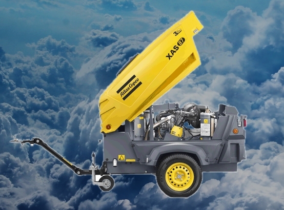
 Руководство по эксплуатации
Винтовые компрессоры: нагнетание воздуха производится с помощью блока, состоящего из двух винтов, имеющих ассиметричный профиль, и вращающихся навстречу друг другу. Применяются в тех случаях, когда необходима длительная и бесперебойная подача сжатого воздуха, в том числе круглосуточная. Наибольшее распространение получили на производствах, где необходимо обеспечивать непрерывный цикл технологических процессов и высокую экономию.
Поршневые компрессоры: нагнетание воздуха производится с помощью цилиндро-поршневой группы. Из-за сильного нагрева от трения деталей компрессоры этого типа имеют развитую систему охлаждения, обычно, воздушную с принудительным обдувом. Наиболее часто поршневые компрессоры применяются для производства сжатого воздуха с частыми перерывами и для работы пневмоинструмента. Хорошо переносят эксплуатацию в тяжелых условиях.
Спиральные компрессоры: принцип работы основан на взаимодействии двух спиральных, коаксиально расположенных профилей один из которых неподвижен, а второй совершает до 10000 вращательных движений в минуту благодаря чему получается равномерное (без пульсаций) производство сжатого воздуха. В компрессорном блоке спиральных компрессоров не используется масло благодаря чему на изначальном уровне обеспечивается абсолютное отсутствие частиц масла в производимом воздухе.
нет Кол-во ступеней сжатия: 1 Напряжение питания V: — Массогабаритные характеристики Размеры мм: 3640x1410x1258 Вес кг: 1060 Дополнительная информация и характеристики Страна происхождения: Бельгия-Швеция Безмасляный: — Фильтр: — Водяное охлаждение: — Передвижной: Да На колесах: Да Двигатель Производитель: Deutz Модель: D2011L03*** Кол-во цилиндров: 3 Число оборотов/мин. max: 2750 Число оборотов/мин. min: 1850 Расход топлива кг/ч max: 8.1 Расход топлива кг/ч на х/х: 3.6 Тип системы охлаждения: Масл. Емкость масляной системы л: 8.5 Емкость топливного бака л: 80 Нормы по выхлопу: COMM III
 Компрессор Atlas Copco XAS 97 установлен на прочную раму, оснащенную колесным шасси. Для защиты компрессора XAS 97 от грязи и атмосферных осадков имеется прочный, шумозащитный кожух современной конструкции из оцинкованной стали, окрашенной порошковой краской. Для удобства повседневного обслуживания и проведения ремонтных работ предусмотрена возможность легкого открытия кожуха. Для подключения потребителей компрессор оборудован тремя выходными патрубками размером 3/4″. Продолжительное время работы компрессора Atlas Copco XAS 97 обеспечивается благодаря вместительному топливному баку объемом 80 литров.
В качестве управляющих элементов компрессора Atlas Copco XAS 97 используются регулирующие клапаны, срабатывающие при изменении давления в ресивере. В случае увеличения потребления сжатого воздуха система управления реагирует на уменьшение давления увеличением оборотов силового агрегата и открытием входного клапана. При уменьшении потребления сжатого воздуха происходит обратный процесс, при котором уменьшаются обороты двигателя, и закрывается входной клапан. Благодаря такому алгоритму компрессор Atlas Copco XAS 97 обеспечивает производство сжатого воздуха точно в соответствии с его потребностями, экономя, таким образом, ресурс основных узлов и потребление топлива.
Система управления компрессора XAS 97 контролирует возможные аварийные ситуации и выдает предупреждение оператору в случае их возникновения. Если причина не устраняется, система обеспечивает аварийную остановку компрессора. Осуществляется контроль следующих параметров:
— температура сжатого воздуха на выходе из компрессора XAS 97;
— отклонение давления компрессорного масла;
— температуры и уровня охлаждающей жидкости;
— давления масла в силовом агрегате;
Производительность компрессора — 5,3 м³/мин. Дизельный компрессор Atlas Copco XAS 97 DdG представлен со встроенным генератором, благодаря чему с его помощью одновременно может работать как пневматический, так и электрический инструмент. Система предназначена для работы тяжелых шахтных перфораторов или буров, при этом расход топлива у системы – минимален (8,1 л). Для перемещения по дорогам общего пользования, под заказ устанавливаются дорожные шасси с ПТС для регистрации в органах ГИБДД.
Среди конкурентных преимуществ компрессоров серии XAS значатся экономичность, низкий уровень шума, модульная конструкция, сверхнадежный защитный корпус, агрегатирование современными и надежными двигателями немецкой марки Deutz.
У нас вы можете купить дизельный компрессор Атлас Копко ХАС 186 Dd по цене производителя, так как мы являемся официальным дилером Атлас Копко в России. Также у вас есть возможность заказать модель в базовой комплектации или наделить ее дополнительными опциями, что заметно улучшит ее эксплуатационные характеристики.
Руководства по эксплуатации
Технические характеристики компрессорной станции XAS97
- Минимальное рабочее давление 4 бар
- Максимальное давление в ресивере 9 бар (компрессор не загружен, выходной клапан закрыт)
- Максимальная рабочая температура окружающей среды + 50°C
- Минимальная температура гарантированного запуска — 10°C (без системы холодного старта).
- Минимальная температура гарантированного запуска с системой холодного старта −20°C (поставляется по заказу).
- Минимальная рабочая температура окружающей среды — 30°C
- Максимальная высота эксплуатации над уровнем моря 4000 м
| 8. Компрессор | ||
|---|---|---|
| Рабочее давление (избыточное) | бар | 7 |
| Производительность по ISO 1217 ed. 3. 1996 | м3/мин | 5,3 |
| Количество ступеней сжатия | шт. | 1 |
| Емкость масляной системы компрессора | литр | 8 |
| Вынос масла на 100% мощности | г/час | 0,95 |
| Мощность шума по 2000/14 ЕС | дБ(А) | 98 |
| Шумовое давление по ISO 2151 на 7 метрах | дБ(А) | 72 |
| Количество постов ѕ дюйма | шт. | 3 |
| Количество постов большого диаметра | шт. | — |
| Максимальная наружная температура *** | °С | +45 |
| 9. Двигатель | ||
| Дизельный двигатель | Deutz | |
| Модель | D2011L03 | |
| Нормы по выхлопу | Tier III | |
| Число цилиндров | шт. | 3 |
| Мощность | кВт | 36 |
| Число оборотов максимум | об/мин | 2750 |
| Число оборотов минимум | об/мин | 1850 |
| Расход топлива | ||
| — на максимальной мощности | кг/ч | 8,1 |
| — на холостом ходу | кг/ч | 3,6 |
| Система охлаждения | тип | Масл. |
| Емкость системы охлаждения | литр | — |
| Емкость масляной системы | литр | 8,5 |
| Емкость топливного бака | литр | 80 |
| 10. Габариты и вес | ||
| Длина с регулируемым дышлом | мм | 3676 |
| Длина с нерегулируемым дышлом | мм | 3063 |
| Ширина на шасси | мм | 1410 |
| Высота на шасси | мм | 1258 |
| Длина без шасси | мм | 2018 |
| Ширина без шасси | мм | 1038 |
| Высота на опорах (салазках) | мм | 1230 |
| Высота без шасси | мм | 970 |
| Вес сухой с шасси | кг | 885 |
| Вес рабочий с шасси | кг | 1060 |
| Вес рабочий на опорах (салазках) | кг | 850 |
Технические характеристики XAS 47
- Минимальное рабочее давление 3 бар
- Максимальное давление в ресивере 8,7 бар (компрессор не загружен, выходной клапан закрыт)
- Максимальная рабочая температура окружающей среды + 50°C
- Минимальная температура гарантированного запуска — 10°C (без системы холодного старта)
- Минимальная температура гарантированного запуска с системой холодного старта −20°C. (поставляется по заказу)
- Минимальная рабочая температура окружающей среды — 30°C
- Максимальная высота эксплуатации над уровнем моря 4000 м
| 8. Компрессор | ||
|---|---|---|
| Рабочее давление (избыточное) | бар | 7 |
| Производительность по ISO 1217 ed. 3. 1996 | м3/мин | 2,6 |
| Количество ступеней сжатия | шт. | 1 |
| Емкость масляной системы компрессора | литр | 8 |
| Вынос масла на 100% мощности | г/час | 0,46 |
| Мощность шума по 2000/14 ЕС | дБ(А) | 98 |
| Шумовое давление по ISO 2151 на 7 метрах | дБ(А) | 70 |
| Количество постов 3/4 дюйма | шт. | 2 |
| Количество постов большого диаметра | шт. | — |
| Максимальная наружная температура *** | °С | +45 |
| 7. Двигатель | ||
| Дизельный двигатель | Deutz | |
| Модель | D2011L02 | |
| Нормы по выбросам | Tier 3 | |
| Число цилиндров | шт. | 2 |
| Мощность | кВт | 21,6 |
| Число оборотов максимум | об/мин | 2400 |
| Число оборотов минимум | об/мин | 1850 |
| Расход топлива | ||
| — на максимальной мощности | кг/ч | 4,2 |
| — на холостом ходу | кг/ч | 2,4 |
| Система охлаждения | тип | масл. |
| Емкость системы охлаждения | литр | — |
| Емкость масляной системы | литр | 8 |
| Емкость топливного бака | литр | 40 |
| 8. Габариты и вес | ||
| Длина с регулируемым дышлом | мм | 3640 |
| Длина с нерегулируемым дышлом | мм | 3105 |
| Ширина на шасси | мм | 1330 |
| Высота на шасси | мм | 1252 |
| Длина без шасси | мм | 1884 |
| Ширина без шасси | мм | 960 |
| Высота на опорах (салазках) | мм | 1230 |
| Высота без шасси | мм | 970 |
| Вес сухой с шасси | кг | 700 |
| Вес рабочий с шасси | кг | 850 |
| Вес рабочий на опорах (салазках) | кг | 635 |
Технические характеристики XAS 67
- Минимальное рабочее давление 3 бар
- Максимальное давление в ресивере 8,7 бар (компрессор не загружен, выходной клапан закрыт).
- Максимальная рабочая температура окружающей среды + 50°C.
- Минимальная температура гарантированного запуска — 10°C (без системы холодного старта)
- Минимальная температура гарантированного запуска с системой холодного старта −20°C (поставляется по заказу)
- Минимальная рабочая температура окружающей среды — 30°C
- Максимальная высота эксплуатации над уровнем моря 4000 м
| 8. Компрессор | ||
|---|---|---|
| Рабочее давление (избыточное) | бар | 7 |
| Производительность по ISO 1217 ed. 3. 1996 | м3/мин | 3,7 |
| Количество ступеней сжатия | шт. | 1 |
| Емкость масляной системы компрессора | литр | 8 |
| Вынос масла на 100% мощности | г/час | 0,66 |
| Мощность шума по 2000/14 ЕС | дБ(А) | 98 |
| Шумовое давление по ISO 2151 на 7 метрах | дБ(А) | 70 |
| Количество постов 3/4 дюйма | шт. | 2 |
| Количество постов большого диаметра | шт. | — |
| Максимальная наружная температура *** | °С | +45 |
| 9. Двигатель | ||
| Дизельный двигатель | Deutz | |
| Модель | D2011L3 | |
| Нормы по выхлопу | Tier III | |
| Число цилиндров | шт. | 3 |
| Мощность | кВт | 32,5 |
| Число оборотов максимум | об/мин | 2400 |
| Число оборотов минимум | об/мин | 1850 |
| Расход топлива | ||
| — на максимальной мощности | кг/ч | 5,9 |
| — на холостом ходу | кг/ч | 3,1 |
| Система охлаждения | тип | масл. |
| Емкость системы охлаждения | литр | — |
| Емкость масляной системы | литр | 8,5 |
| Емкость топливного бака | литр | 80 |
| 10. Габариты и вес | ||
| Длина с регулируемым дышлом | мм | 3676 |
| Длина с нерегулируемым дышлом | мм | 3063 |
| Ширина на шасси | мм | 1410 |
| Высота на шасси | мм | 1258 |
| Длина без шасси | мм | 2018 |
| Ширина без шасси | мм | 1038 |
| Высота на опорах (салазках) | мм | 1230 |
| Высота без шасси | мм | 970 |
| Вес сухой с шасси | кг | 885 |
| Вес рабочий с шасси | кг | 1060 |
| Вес рабочий на опорах (салазках) | кг | 850 |