- Manuals
- Brands
- Yamaha Manuals
- Motorcycle
- BOLT 2019
- Owner’s manual
-
Contents
-
Table of Contents
-
Troubleshooting
-
Bookmarks
Quick Links
Read this manual carefully before operating this vehicle.
OWNER’S MANUAL
XVS95CL
XVS95CLC
LIT-11626-33-31
BP6-28199-13
Related Manuals for Yamaha BOLT 2019
Summary of Contents for Yamaha BOLT 2019
-
Page 1
Read this manual carefully before operating this vehicle. OWNER’S MANUAL XVS95CL XVS95CLC LIT-11626-33-31 BP6-28199-13… -
Page 2
EAU10045 Operating, servicing and maintaining a passenger vehicle or off-road vehicle can expose you to chemicals including engine exhaust, carbon monoxide, phthalates, and lead, which are known to the State of California to cause cancer and birth defects or other reproductive harm. To minimize exposure, avoid breathing exhaust, do not idle the engine except as necessary, service your vehicle in a well-ventilated area and wear gloves or wash your… -
Page 3
Yamaha has met these standards without reducing the performance or economy of operation of the motorcycle. To maintain these high standards, it is important that you and your Yamaha dealer pay close attention to the recommended maintenance schedules and operating instructions contained within this manual. -
Page 4
Important manual information EAU10134 Particularly important information is distinguished in this manual by the following notations: This is the safety alert symbol. It is used to alert you to potential personal injury hazards. Obey all safety messages that follow this symbol to avoid possible injury or death. -
Page 5
Important manual information EAU10194 XVS95CL / XVS95CLC OWNER’S MANUAL ©2020 by Yamaha Motor Corporation, U.S.A. 1st edition, June 2019 All rights reserved. Any reprinting or unauthorized use without the written permission of Yamaha Motor Corporation, U.S.A. is expressly prohibited. Printed in Japan. -
Page 6: Table Of Contents
Table of contents Location of important labels… 1-1 For your safety – pre-operation Checking the brake lever free checks ……….5-1 play……….7-20 Safety information……2-1 Brake light switches ….. 7-21 Operation and important riding Checking the front and rear Description ……..3-1 points ……….6-1 brake pads ……..
-
Page 7
Diagnostic connector ….10-3 Vehicle data recording ….10-3 Reporting safety defects ….10-4 Motorcycle noise regulation ..10-5 Maintenance record ……10-6 YAMAHA MOTOR CORPORATION, U.S.A. 2020 AND LATER MODEL STREET & DUAL-PURPOSE MOTORCYCLE LIMITED WARRANTY …….10-8 YAMAHA EXTENDED SERVICE (Y.E.S.) ……..10-10 Index ……….11-1… -
Page 8: Location Of Important Labels
Read and understand all of the labels on your vehicle. They contain important information for safe and proper operation of your vehicle. Never remove any labels from your vehicle. If a label becomes difficult to read or comes off, a replacement label is available from your Yamaha dealer.
-
Page 9
Location of important labels 1 California only 2 California only VACUUM HOSE ROUTING EMISSION HOSE ROUTING PRESS. SENSOR THROTTLE BODY FUEL TANK ATMOSPHERE CANISTER INTAKE MANIFOLD 34B-21684-00 5RU-21686-00 3 Bolt R-Spec WARNING TIRE INFORMATION This unit contains high pressure nitrogen gas. Col d t i r e no r m al p r e ssu r e s houl d be s et as fo l l ows. -
Page 10: Safety Information
Safety information Never operate a motorcycle with- pears to be very effective in reduc- EAU40959 out proper training or instruction. ing the chance of this type of Take a training course. Beginners accident. Be a Responsible Owner should receive training from a cer- Therefore: As the vehicle’s owner, you are re- tified instructor.
-
Page 11
Safety information Many accidents involve inexperi- The use of a jacket, heavy boots, • Always signal before turning or enced operators. In fact, many op- changing lanes. Make sure that trousers, gloves, etc., is effective erators who have been involved in other motorists can see you. -
Page 12
To Yamaha accessories, which are avail- instability. avoid the possibility of an accident, use able only from a Yamaha dealer, have Shifting weights can create a sud- extreme caution when adding cargo or been designed, tested, and approved den imbalance. -
Page 13
Never install accessories or carry for Yamaha vehicles. Yamaha is not in passed by large vehicles. a position to test the products that cargo that would impair the per- •… -
Page 14
Safety information may not be appropriate. Refer to page the location for the straps carefully 7-16 for tire specifications and more in- so the straps will not rub against formation on replacing your tires. painted surfaces during transport. The suspension should be com- Transporting the Motorcycle pressed somewhat by the tie- Be sure to observe following instruc-… -
Page 15: Description
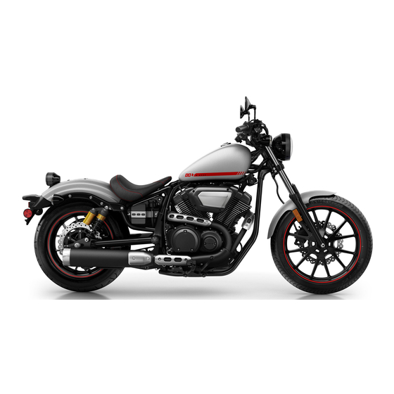
Description EAU32221 Left view Bolt 1. Headlight (page 7-31) 2. Tool kit (page 7-2) 3. Spring preload adjuster (page 4-13) 4. Fuses (page 7-29) 5. Engine oil drain bolt (page 7-11) 6. Shift pedal (page 4-7) 7. Engine oil filler cap (page 7-11)
-
Page 16
Description Bolt R-Spec 1. Headlight (page 7-31) 2. Tool kit (page 7-2) 3. Spring preload adjuster (page 4-13) 4. Fuses (page 7-29) 5. Engine oil drain bolt (page 7-11) 6. Shift pedal (page 4-7) 7. Engine oil filler cap (page 7-11) -
Page 17: Right View
Description EAU32231 Right view Bolt 1. License plate light (page 7-33) 8. Steering lock (page 4-11) 2. Brake/tail light (page 7-32) 9. Engine oil filter cartridge (page 7-11) 3. Battery (page 7-28) 10.Rear brake light switch (page 7-21) 4. Rear brake fluid reservoir (page 7-22) 11.Brake pedal (page 4-7) 5.
-
Page 18
Description Bolt R-Spec 1. License plate light (page 7-33) 10.Rear brake light switch (page 7-21) 2. Brake/tail light (page 7-32) 11.Brake pedal (page 4-7) 3. Battery (page 7-28) 4. Rear brake fluid reservoir (page 7-22) 5. Air filter element (page 7-15) 6. -
Page 19: Controls And Instruments
Description EAU10431 Controls and instruments 1. Clutch lever (page 4-6) 2. Left handlebar switches (page 4-5) 3. Multi-function meter unit (page 4-3) 4. Front brake fluid reservoir (page 7-22) 5. Right handlebar switches (page 4-5) 6. Brake lever (page 4-7) 7.
-
Page 20: Instrument And Control Functions
Instrument and control functions EAU55831 EAU85040 EAU4939G Main switch Indicator lights and warning All electrical circuits are supplied with lights power and the vehicle lights are turned 1 2 3 on. The engine can be started. The key cannot be removed. …
-
Page 21
Yamaha dealer check the vehi- tion or deceleration, but this is not a cle. This warning light will come on when malfunction. -
Page 22: Multi-Function Meter Unit
Instrument and control functions a clock Odometer, tripmeters, fuel reserve EAU55694 Multi-function meter unit a self-diagnosis device tripmeter and clock The key must be turned to “ON” before you can use the “SELECT” and “RESET” switches. To switch between miles and kilo- meters, push “SELECT”…
-
Page 23
5. Push the “RESET” switch for two manually, or after refueling and travel- Yamaha dealer check the vehicle. seconds to confirm settings and ing 5 km (3 mi) it will reset automatically start the clock. -
Page 24: Handlebar Switches
Instrument and control functions Right ECA11591 EAU1234M Handlebar switches NOTICE If the display indicates an error Left code, the vehicle should be checked as soon as possible in order to avoid engine damage. 1. Engine stop switch “ ” 2. “SELECT” switch 3.
-
Page 25: Clutch Lever
Instrument and control functions has traveled both about 150 m (490 ft) EAU12713 EAU12822 Start switch “ ” Clutch lever and for approximately 15 seconds. Push this switch to crank the engine However, the turn signal lights can also with the starter. See page 6-1 for start- be canceled manually by pushing the ing instructions prior to starting the en- switch in after it has returned to the…
-
Page 26: Shift Pedal
Instrument and control functions EAU12875 EAU12892 EAU12944 Shift pedal Brake lever Brake pedal 1. Shift pedal 1. Brake lever 1. Brake pedal The shift pedal is located on the left The brake lever is located on the right The brake pedal is located on the right side of the motorcycle.
-
Page 27: Fuel Tank Cap
Instrument and control functions 2. Turn the key counterclockwise to EAU13125 EAU13222 Fuel tank cap Fuel the original position, remove it, Make sure there is sufficient gasoline in and then close the lock cover. the tank. EWA10882 WARNING The fuel tank cap cannot be installed unless the key is in the lock.
-
Page 28
WARNING as well as to the exhaust system. Gasoline is poisonous and can Your Yamaha engine has been de- cause injury or death. Handle gaso- signed to use regular unleaded gaso- line with care. Never siphon gasoline line with a pump octane number by mouth. -
Page 29: Fuel Tank Breather/Overflow Hose
Instrument and control functions Make sure that the fuel tank EAU48792 EAU13434 Fuel tank breather/overflow Catalytic converter breather/overflow hose is routed hose This model is equipped with a catalytic through the clamp. converter in the exhaust system. EWA10863 WARNING The exhaust system is hot after op- eration.
-
Page 30: Steering Lock
Instrument and control functions To unlock the steering ECA10702 EAU55663 Steering lock NOTICE The steering lock is located on the right Use only unleaded gasoline. The use side of the vehicle between the upper of leaded gasoline will cause unre- and lower steering brackets.
-
Page 31: Seat
Instrument and control functions EAU55653 Seat To remove the seat 1. Remove panel A. (See page 7-9.) 2. Remove the bolt. 1. Projection 1. Rubber damper 2. Seat holder Tightening torque: 2. Place the seat in the original posi- Seat fitting bolt: tion.
-
Page 32: Adjusting The Shock Absorber Assemblies
Instrument and control functions Bolt EAU80052 Adjusting the shock absorber assemblies Each shock absorber assembly is equipped with a spring preload adjust- ing ring. EWA10211 WARNING Always adjust both shock absorber assemblies equally, otherwise poor 1. Extension bar handling and loss of stability may re- 2.
-
Page 33: Sidestand
1. Spring preload adjusting ring worn-out shock absorber as- explanation of the ignition circuit cut- 2. Stopper sembly yourself. Take the shock off system.) absorber assembly to a Yamaha Spring preload setting: EWA10242 Minimum (soft): dealer for any service. WARNING…
-
Page 34: Ignition Circuit Cut-Off System
Instrument and control functions this system regularly and have a EAU44895 Ignition circuit cut-off system Yamaha dealer repair it if it does not This system prevents in-gear engine function properly. starts unless the clutch lever is pulled and the sidestand is up. Also, it will…
-
Page 35
The neutral switch may not be working. 6. Move the sidestand up. The motorcycle should not be ridden until 7. Pull the clutch lever. checked by a Yamaha dealer. 8. Shift transmission into gear. 9. Move the sidestand down. Does the engine stall? The sidestand switch may not be working. -
Page 36: For Your Safety — Pre-Operation Checks
• If necessary, add recommended oil to specified level. 7-11 • Check vehicle for oil leakage. • Check operation. • If soft or spongy, have Yamaha dealer bleed hydraulic system. • Check brake pads for wear. Front brake • Replace if necessary.
-
Page 37
• Make sure that operation is smooth. • Check throttle grip free play. Throttle grip 7-15, 7-24 • If necessary, have Yamaha dealer adjust throttle grip free play and lubricate ca- ble and grip housing. • Make sure that operation is smooth. Control cables 7-24 •… -
Page 38
For your safety – pre-operation checks ITEM CHECKS PAGE • Check operation of ignition circuit cut-off system. 4-14 Sidestand switch • If system is not working correctly, have Yamaha dealer check vehicle. -
Page 39: Operation And Important Riding Points
a lean angle sensor to stop the en- The transmission is in the neutral understand, ask your Yamaha dealer. gine in case of a turnover. In this EWA10272 position.
-
Page 40: Shifting
NOTICE neutral position. The neutral indi- Even with the transmission in cator light should come on. If not, ask a Yamaha dealer to check the the neutral position, do not electrical circuit. coast for long periods of time 3. Start the engine by pushing the with the engine off, and do not start switch.
-
Page 41: Engine Break-In
Operation and important riding points 4. At the recommended shift points 3. Shift the transmission into the EAU16842 Engine break-in shown in the following table, close neutral position when the motor- There is never a more important period the throttle, and at the same time, cycle almost completely…
-
Page 42: Parking
If any engine trouble should occur WARNING during the engine break-in period, Since the engine and exhaust immediately have a Yamaha dealer system can become very hot, check the vehicle. park in a place where pedestri- ans or children are not likely to touch them and be burned.
-
Page 43: Periodic Maintenance And Adjustment
To avoid possible burns, let tivities incorrectly may increase brake components cool before your risk of injury or death during touching them. service or while using the vehicle. If you are not familiar with vehicle ser- vice, have a Yamaha dealer perform service.
-
Page 44: Tool Kits
EAU85240 Tool kits If you do not have the tools or experi- ence required for a particular job, have your Yamaha dealer perform it for you. 1. Tool box 2. Tool kit The on–board tool kit is in the location shown.
-
Page 45: Periodic Maintenance Chart For The Emission Control System
From 24000 mi (37000 km) or 36 months, repeat the maintenance intervals starting from 8000 mi (13000 km) or 12 months. Items marked with an asterisk require special tools, data and technical skills, have a Yamaha dealer perform the ser- vice.
-
Page 46
Periodic maintenance and adjustment INITIAL ODOMETER READINGS 600 mi 4000 mi 8000 mi 12000 mi 16000 mi 20000 mi ITEM ROUTINE (1000 km) (7000 km) (13000 km) (19000 km) (25000 km) (31000 km) 1 month 6 months 12 months 18 months 24 months 30 months •… -
Page 47: General Maintenance And Lubrication Chart
30 months • Perform dynamic inspection us- Diagnostic system √ √ √ √ √ √ ing Yamaha diagnostic tool. check • Check the error codes. Air filter element • Replace. Every 24000 mi (37000 km) • Check operation. √ √…
-
Page 48
Periodic maintenance and adjustment INITIAL ODOMETER READINGS 600 mi 4000 mi 8000 mi 12000 mi 16000 mi 20000 mi ITEM ROUTINE (1000 km) (7000 km) (13000 km) (19000 km) (25000 km) (31000 km) 1 month 6 months 12 months 18 months 24 months 30 months •… -
Page 49
• Replace. tridge Front and rear √ √ √ √ √ √ 25 * • Check operation. brake switches • Apply Yamaha cable lubricant or √ √ √ √ √ √ 26 * Control cables other suitable cable lubricant thoroughly. -
Page 50
Periodic maintenance and adjustment INITIAL ODOMETER READINGS 600 mi 4000 mi 8000 mi 12000 mi 16000 mi 20000 mi ITEM ROUTINE (1000 km) (7000 km) (13000 km) (19000 km) (25000 km) (31000 km) 1 month 6 months 12 months 18 months 24 months 30 months •… -
Page 51: Removing And Installing The Panel
Periodic maintenance and adjustment EAU18752 EAU42433 Removing and installing the Checking the spark plugs panel The spark plugs are important engine components, which are easy to check. The panel shown needs to be removed Since heat and deposits will cause any to perform some of the maintenance spark plug to slowly erode, the spark jobs described in this chapter.
-
Page 52
Do not attempt to with the spark plug wrench includ- diagnose such problems yourself. In- ed in the additional tool kit, which stead, have a Yamaha dealer check was handed out separately at the the vehicle. purchase of the vehicle. -
Page 53: Canister (For California)
Periodic maintenance and adjustment To install a spark plug EAU19683 EAU47115 Canister (for California) Engine oil and oil filter car- 1. Clean the surface of the spark tridge plug gasket and its mating sur- The engine oil level should be checked face, and then wipe off any grime THROTTLE BODY FUEL TANK…
-
Page 54
Periodic maintenance and adjustment 5. If the engine oil is at or below the minimum level mark, add suffi- The engine oil should be between the cient oil of the recommended type minimum and maximum level marks. to raise it to the correct level. 6. -
Page 55
Periodic maintenance and adjustment Recommended engine oil: See page 9-1. An oil filter wrench is available at a Oil quantity: Yamaha dealer. Oil change: 3.70 L (3.91 US qt, 3.26 Imp.qt) 5. Apply a thin coat of clean engine With oil filter removal: oil to the O-ring of the new oil filter 4.00 L (4.23 US qt, 3.52 Imp.qt) -
Page 56: Why Yamalube
We form off and have a Yamaha dealer check teams of specialists in the fields of me- the vehicle. chanical engineering, chemistry, elec- 12.
-
Page 57: Replacing The Air Filter Element
4.0–6.0 mm (0.16–0.24 in) piston(s) and/or cylinder(s) may Periodically check the throttle grip free become excessively worn. play and, if necessary, have a Yamaha [ECA10482] dealer adjust it. 4. Install the air filter case cover by installing the bolts. 1. Bolt 2.
-
Page 58: Valve Clearance
Vehicle: To prevent this from occurring, have 207 kg (456 lb) your Yamaha dealer check and adjust Tire air pressure The vehicle’s maximum load is the combined weight of the rider, cargo, the valve clearance at regular intervals.
-
Page 59
Yamaha quality product. could lead to an accident. dealer replace the tire immediately. -
Page 60: Wheels
WARNING ride. If any damage is found, have The wheels on this model are not a Yamaha dealer replace the designed for use with tubeless tires. wheel. Do not attempt even the Do not attempt to use tubeless tires smallest repair to the wheel.
-
Page 61: Adjusting The Clutch Lever Free Play
If any damage is 3. Fully turn the adjusting bolt at the found, have a Yamaha dealer re- clutch lever in direction (a) to loos- en the clutch cable. place the wheel. Do not attempt 4.
-
Page 62: Checking The Brake Lever Free Play
1. No brake lever free play There should be no free play at the brake lever end. If there is free play, have a Yamaha dealer inspect the brake system. EWA14212 WARNING A soft or spongy feeling in the brake lever can indicate the presence of air in the hydraulic system.
-
Page 63: Brake Light Switches
The front brake light switch should be The brake light is activated by switches brake pads serviced by a Yamaha dealer. connected to the brake lever and brake The front and rear brake pads must be pedal. Check that the brake light…
-
Page 64: Checking The Brake Fluid Level
Rear brake EAU22583 Checking the brake fluid level peared, have a Yamaha dealer replace Before riding, check that the brake fluid the brake pads as a set. is above the minimum level mark. Check the brake fluid level with the res-…
-
Page 65: Changing The Brake Fluid
Insufficient brake fluid may al- EAU22734 EAU23041 Changing the brake fluid Drive belt slack low air to enter the brake sys- Have a Yamaha dealer change the The drive belt slack should be checked tem, reducing braking brake fluid every 2 years. In addition, and adjusted at the intervals specified performance.
-
Page 66: Checking And Lubricating The Cables
Yamaha dealer at the intervals cated if necessary. If a cable is specified in the periodic maintenance damaged or does not move smoothly, chart.
-
Page 67: Checking And Lubricating The Brake And Shift Pedals
Periodic maintenance and adjustment EAU44276 EAU23144 Recommended lubricant: Checking and lubricating the Checking and lubricating the Lithium-soap-based grease brake and shift pedals brake and clutch levers The operation of the brake and shift The operation of the brake and clutch pedals should be checked before each levers should be checked before each ride, and the pedal pivots should be lu-…
-
Page 68: Checking And Lubricating The Sidestand
The operation of the sidestand should The swingarm pivots must be lubricat- be checked before each ride, and the ed by a Yamaha dealer at the intervals sidestand pivot and metal-to-metal specified in the periodic maintenance contact surfaces should be lubricated and lubrication chart.
-
Page 69: Checking The Front Fork
[EWA10752] tion. WARNING! To avoid injury, 2. Hold the lower ends of the front have a Yamaha dealer check or re- securely support the vehicle so fork legs and try to move them for- pair it.
-
Page 70: Checking The Wheel Bearings
EWA10761 WARNING To charge the battery Electrolyte is poisonous and Have a Yamaha dealer charge the bat- dangerous since it contains sul- tery as soon as possible if it seems to furic acid, which causes severe have discharged. Keep in mind that the…
-
Page 71: Replacing The Fuses
Periodic maintenance and adjustment battery tends to discharge more quick- nect the positive lead before EAU55674 Replacing the fuses ly if the vehicle is equipped with op- connecting the negative lead. The main fuse, the fuel injection sys- tional electrical accessories. [ECA16842] tem fuse, and the fuse box, which con- ECA16522…
-
Page 72
4. If the fuse immediately blows To access the fuel injection system amperage. WARNING! Do not again, have a Yamaha dealer fuse, remove the starter relay cover by use a fuse of a higher amperage check the electrical system. -
Page 73: Replacing The Headlight Bulb
Periodic maintenance and adjustment EAU63180 Replacing the headlight bulb This model is equipped with a halogen bulb headlight. If the headlight bulb burns out, replace it as follows. ECA10661 NOTICE Do not touch the glass part of the headlight bulb to keep it free from oil, otherwise the transparency of 1.
-
Page 74: Brake/Tail Light
Yamaha dealer check it. 1. “TOP” mark 6. Install the headlight unit by install- ing the screws. 7. Have a Yamaha dealer adjust the headlight beam if necessary. 1. Screw 2. Turn signal light lens 2. Remove the burnt-out bulb by pushing it in and turning it coun- terclockwise.
-
Page 75: License Plate Light
Supporting the motorcycle If the license plate light does not come Since this model is not equipped with a on, have a Yamaha dealer check the centerstand, follow these precautions electrical circuit or replace the bulb. when removing the front and rear…
-
Page 76: Troubleshooting
However, should your motorcycle require any repair, take it to a Yamaha dealer, whose skilled technicians have the necessary tools, experience, and know-how to service the motorcycle properly.
-
Page 77: Troubleshooting Chart
Remove the spark plugs and check the electrodes. The engine does not start. Have a Yamaha dealer check the vehicle. Check the compression. 4. Compression The engine does not start. There is compression.
-
Page 78: Motorcycle Care And Storage
Be performance and extend the useful life high-pressure washers sure to consult a Yamaha dealer for of many components. Washing, clean- steam-jet cleaners. Excessive ing, and polishing will also give you a advice on what products to use be-…
-
Page 79
Motorcycle care and storage chemicals such as, solvents, Washing windshield. Additionally, some gasoline, rust removers, brake 1. Rinse off any degreaser and spray cleaning compounds for plastic down the vehicle with a garden fluid, or antifreeze, etc. may scratch the windshield, so hose. -
Page 80: Storage
Motorcycle care and storage ply silicone or oil spray to seats, ECA26320 EAU84141 Storage NOTICE hand grips, rubber foot pegs or Always store the vehicle in a cool, dry Do not apply wax to rubber or tire treads. Otherwise these place.
-
Page 81
Motorcycle care and storage 1. Make all necessary repairs and a. Remove the spark plug cap 8. Check and correct the tire air perform any outstanding mainte- and spark plug. pressure, and then lift the vehicle nance. b. Pour a teaspoonful of engine so that all wheels are off the 2. -
Page 82: Specifications
Specifications Dimensions: Starting system: Fuel: Electric starter Overall length: Recommended fuel: Engine oil: 2290 mm (90.2 in) Regular unleaded gasoline (Gasohol [E10] Overall width: Recommended brand: acceptable) 830 mm (32.7 in) Fuel tank capacity: Overall height: 13 L (3.4 US gal, 2.9 Imp.gal) 1120 mm (44.1 in) Fuel reserve amount: Seat height:…
-
Page 83
Specifications Manufacturer/model: Electrical system: BRIDGESTONE/EXEDRA G721 F (Cast System voltage: wheel) 12 V BRIDGESTONE/EXEDRA G721 L (Spoke Battery: wheel) Model: Rear tire: YTZ14S Type: Voltage, capacity: Tubeless (Cast wheel) 12 V, 11.2 Ah (10 HR) With tube (Spoke wheel) Headlight: Size: Bulb type: 150/80B16M/C 71H… -
Page 84: Consumer Information
Vehicle identification number ed when registering the vehicle with the authorities in your area and when EAU26442 Engine serial number ordering spare parts from a Yamaha dealer. VEHICLE IDENTIFICATION NUMBER: 1. Vehicle identification number ENGINE SERIAL NUMBER: The vehicle identification number is 1.
-
Page 85
This information will it for reference when ordering a new illustration. This label shows specifica- be needed when ordering spare parts key. tions related to exhaust emissions as from a Yamaha dealer. required by federal law, state law and Environment Canada. 10-2… -
Page 86: Diagnostic Connector
Although the sensors and recorded data will vary by model, the main data Yamaha will not disclose this data to a points are: third party except in the following cas- Vehicle status and engine perfor- es.
-
Page 87: Reporting Safety Defects
If you believe that your vehicle has a defect which could cause a crash or could cause injury or death, you should immedi- ately inform the National Highway Traffic Safety Administration (NHTSA) in addition to notifying Yamaha Motor Corporation, U.S.A. If NHTSA receives similar complaints, it may open an investigation, and if it finds that a safety defect exists in a group of vehicles, it may order a recall and remedy campaign.
-
Page 88: Motorcycle Noise Regulation
Consumer information EAU26561 Motorcycle noise regulation TAMPERING WITH NOISE CONTROL SYSTEM PROHIBITED: Federal law prohibits the following acts or the causing thereof: (1) The removal or rendering inoperative by any person other than for purposes of maintenance, repair, or replacement of any device or element of design incorporated into any new vehicle for the purpose of noise control prior to its sale or delivery to the ultimate purchaser or while it is in use or (2) the use of the vehicle after such device or element of design has been removed or rendered inoperative by any person.
-
Page 89: Maintenance Record
Consumer information EAU26633 Maintenance record Copies of work orders and/or receipts for parts purchased and installed on your vehicle will be required to document that maintenance has been completed in accordance with the emissions warranty. The chart below is printed only as a reminder that maintenance work is required.
-
Page 90
Consumer information Maintenance Date of Servicing dealer Mileage Remarks interval service name and address 36000 mi (55000 km) or 54 months 40000 mi (61000 km) or 60 months 10-7… -
Page 91
Consumer information EAU61803 YAMAHA MOTOR CORPORATION, U.S.A. 2020 AND LATER MODEL STREET & DUAL-PURPOSE MOTORCYCLE LIMITED WARRANTY ENGINE Yamaha Motor Corporation, U.S.A. hereby warrants that Give notice to an authorized Yamaha motorcycle DISPLACEMENT each new Yamaha motorcycle purchased from an… -
Page 92: Yamaha Motor
CUSTOMER SERVICE What costs are my responsibility during the warranty period? If your machine requires warranty service, you must take it to any authorized Yamaha The customer’s responsibility includes all costs of normal maintenance services, motorcycle dealer within the continental United States. Be sure to bring your warranty non-warranty repairs, accident and collision damages, and oil, oil filters, air filters, registration card or other valid proof of the original date of purchase.
-
Page 93: Yamaha Extended Service (Y.e.s.)
This excellent Y.E.S. plan coverage is only available to warranty. See the sample contract at your Yamaha Yamaha owners like you, and only while your Yamaha is still dealer to see how comforting uninterrupted factory- within the Yamaha Limited Warranty period. So visit your backed protection can be.
-
Page 94
TRIP coverage right away, and you’ll rest easy knowing you’ll have strong factory-backed protection even after your Yamaha Limited Warranty expires. A special note: If visiting your dealer isn’t convenient, contact Yamaha with your VIN number and we’ll be happy to help you get the YAMAHA EXTENDED SERVICE Y.E.S. -
Page 95: Index
Index Air filter element, replacing….7-15 Front and rear brake pads, checking … 7-21 Oil level warning light……4-2 Front fork, checking ……7-27 Fuel …………4-8 Battery ……….7-28 Panel, removing and installing….7-9 Fuel level warning light……4-2 Brake and clutch levers, checking and Parking…………
-
Page 96
Index Troubleshooting ……..7-34 Troubleshooting chart……7-35 Turn signal indicator light …….4-1 Turn signal light bulb, replacing….7-32 Turn signal switch ……..4-5 Valve clearance……..7-16 Vehicle Emission Control Information label …………10-2 Vehicle identification number ….10-1 Warranty, extended ……10-10 Warranty, limited……..10-8 Wheel bearings, checking…..7-28 Wheels ……….7-18 Yamalube……….7-14 11-2… -
Page 97
Yamalube – Take care of your Yamaha with legendary Yamalube oils, lubricants, and care products. They’re formulated and approved by the toughest judges we know: the Yamaha engineering teams that know your Yamaha from the inside out. -
Page 98
PRINTED IN JAPAN 2019.07-0.3×1 CR (E)
Не можете найти ответ на свой вопрос в руководстве? Вы можете найти ответ на свой вопрос ниже, в разделе часто задаваемых вопросов о Yamaha Bolt (2017).
Как перевести мили в километры?
В чем разница между топливом E10 и E5?
Какова рекомендуемая частота замены масляного фильтра в двигателе Yamaha?
Как часто следует менять масло в двигателе Yamaha?
Как удалить ржавчину с устройства Yamaha мотоцикл?
Инструкция Yamaha Bolt (2017) доступно в русский?
Не нашли свой вопрос? Задайте свой вопрос здесь
Read this manual carefully before operating this vehicle.
OWNER’S MANUAL
XVS95CH
BP6-28199-70
[English (E)]
DIC183
UBP670E0.book Page 1 Monday, July 11, 2016 11:29 AM
EAU46091
Rea d this manual carefully b efore operatin g this vehicle. This manual shoul d stay with this vehicle if it is sol d .
UBP670E0.book Page 1 Monday, July 11, 2016 11:29 AM
Intro d uction
EAU45931
Congratulations on your purchase of the Yamaha XVS95CH. This model is the result of Yamaha’s vast experience in the production of fine sporting, touring, and pacesetting racing machines. It represents the high degree of craftsmanship and reliability that have made Yamaha a leader in these fields.
This manual will give you an understanding of the operation, inspection, and basic maintenance of this motorcycle. If you have any questions concerning the operation or maintenance of your motorcycle, please consult a Yamaha dealer.
The design and manufacture of this Yamaha motorcycle fully comply with the emissions standards for clean air applicable at the date of manufacture. Yamaha has met these standards without reducing the performance or economy of operation of the motorcycle. To maintain these high standards, it is important that you and your Yamaha dealer pay close attention to the recommended maintenance schedules and operating instructions contained within this manual.
Yamaha continually seeks advancements in product design and quality. Therefore, while this manual contains the most current product information available at the time of printing, there may be minor discrepancies between your motorcycle and this manual. If there is any question concerning this manual, please consult a Yamaha dealer.
EWA10022
WARNING
Please rea d this manual carefully an d completely b efore operatin g this motorcycle. Do not attempt to operate this motorcycle until you have attaine d a d equate knowle dg e of its controls an d operatin g features an d until you have b een traine d in safe an d proper ri d in g techniques. Re g ular inspections an d careful maintenance, alon g with g oo d ri d in g skills, will ensure that you safely enjoy the capa b ilities an d the relia b ility of this motorcycle.
UBP670E0.book Page 1 Monday, July 11, 2016 11:29 AM
Important manual information
WARNING
EAU10134
Particularly important information is distinguished in this manual by the following notations:
This is the safety alert sym b ol. It is use d to alert you to potential personal injury hazar d s. O b ey all safety messa g es that follow this sym b ol to avoi d possi b le injury or d eath.
A WARNING in d icates a hazar d ous situation which, if not avoi d e d , coul d result in d eath or serious injury.
NOTICE
A NOTICE in d icates special precautions that must b e taken to avoi d d ama g e to the vehicle or other property.
TIP
A TIP provides key information to make procedures easier or clearer.
*Product and specifications are subject to change without notice.
UBP670E0.book Page 2 Monday, July 11, 2016 11:29 AM
Important manual information
EAU10201
XVS95CH
OWNER’S MANUAL
©2016 b y Yamaha Motor Co., Lt d .
1st e d ition, June 2016
All ri g hts reserve d .
Any reprintin g or unauthorize d use without the written permission of
Yamaha Motor Co., Lt d . is expressly prohi b ite d .
Printe d in Japan.
UBP670E0.book Page 1 Monday, July 11, 2016 11:29 AM
Ta b le of contents
Location of important la b els
……….. 1-1
Safety information
………………………. 2-1
Description
………………………………… 3-1
Left view ………………………………….. 3-1
Right view ………………………………… 3-3
Controls and instruments …………… 3-5
Instrument an d control functions
… 4-1
Main switch ……………………………… 4-1
Indicator lights and warning lights…………………………………….. 4-1
Multi-function meter unit ……………. 4-3
Handlebar switches…………………… 4-5
Clutch lever ……………………………… 4-7
Shift pedal ……………………………….. 4-7
Brake lever……………………………….. 4-7
Brake pedal ……………………………… 4-8
Fuel tank cap ……………………………. 4-8
Fuel…………………………………………. 4-9
Fuel tank breather/overflow hose …………………………………… 4-10
Catalytic converter ………………….. 4-10
Steering lock…………………………… 4-11
Rider seat ………………………………. 4-12
Adjusting the shock absorber assemblies ………………………….. 4-13
Sidestand ………………………………. 4-14
Ignition circuit cut-off system ……. 4-15
For your safety – pre-operation checks
………………………………………..5-1
Operation an d important ri d in g points
…………………………………………. 6-1
Starting the engine…………………….. 6-1
Shifting …………………………………….. 6-2
Engine break-in ………………………….6-3
Parking …………………………………….. 6-4
Perio d ic maintenance an d a d justment
…………………………………. 7-1
Owner’s tool kits ……………………….. 7-2
Periodic maintenance chart for the emission control system…………..7-3
General maintenance and lubrication chart……………………… 7-5
Removing and installing the panel …………………………………….. 7-9
Checking the spark plugs …………… 7-9
Engine oil and oil filter cartridge…. 7-11
Replacing the air filter element ….. 7-14
Checking the throttle grip free play …………………………………….. 7-15
Valve clearance ………………………..7-15
Tires ……………………………………….7-15
Wheels …………………………………… 7-17
Adjusting the clutch lever free play …………………………………….. 7-18
Checking the brake lever free play …………………………………….. 7-19
Brake light switches ………………… 7-20
Checking the front and rear brake pads …………………………………… 7-20
Checking the brake fluid level …… 7-21
Changing the brake fluid ………….. 7-22
Drive belt slack ……………………….. 7-23
Checking and lubricating the cables…………………………………. 7-23
Checking and lubricating the throttle grip and cable …………… 7-24
Checking and lubricating the brake and shift pedals…………… 7-24
Checking and lubricating the brake and clutch levers …………. 7-25
Checking and lubricating the sidestand…………………………….. 7-25
Lubricating the swingarm pivots………………………………….. 7-26
Checking the front fork …………….. 7-26
Checking the steering………………. 7-27
Checking the wheel bearings ……. 7-27
Battery …………………………………… 7-27
Replacing the fuses …………………. 7-29
Replacing the headlight bulb…….. 7-30
Brake/tail light…………………………. 7-31
Replacing a turn signal light bulb ……………………………………. 7-32
License plate light……………………. 7-32
Supporting the motorcycle ……….. 7-33
Troubleshooting………………………. 7-33
Troubleshooting chart ……………… 7-35
UBP670E0.book Page 2 Monday, July 11, 2016 11:29 AM
Motorcycle care an d stora g e
……….8-1
Matte color caution …………………….8-1
Care ………………………………………….8-1
Storage ……………………………………..8-3
Specifications
………………………………9-1
Consumer information
……………….10-1
Identification numbers……………….10-1
Maintenance record ………………….10-3
YAMAHA MOTOR CANADA LTD.
MOTORCYCLE WARRANTY
GUIDE ………………………………….10-5
In d ex
…………………………………………11-1
Ta b le of contents
UBP670E0.book Page 1 Monday, July 11, 2016 11:29 AM
1
Location of important la b els
EAU10385
Read and understand all of the labels on your vehicle. They contain important information for safe and proper operation of your vehicle. Never remove any labels from your vehicle. If a label becomes difficult to read or comes off, a replacement label is available from your Yamaha dealer.
1 5,6
3,4 2
1-1
2
UBP670E0.book Page 2 Monday, July 11, 2016 11:29 AM
1
• C
ANADA •
V
S
S
C
T
•
R A
506
N S P O
R
N
S
V
T
CAN ICES-2 / NMB-2
8KM-82377-10
3
TIRE INFORMATION
Cold tire normal pressure should be set as follows.
• Up to 90 kg (198 lbs) load
FRONT
REAR
: 225 kPa, (2.25 kgf/cm²), 33 psi
: 250 kPa, (2.50 kgf/cm²), 36 psi
• 90kg (198 lbs) ~ maximum load
FRONT
: 250 kPa, (2.50 kgf/cm²), 36 psi
REAR
: 280 kPa, (2.80 kgf/cm²), 41 psi
1TP-21668-A0
Location of important la b els
2 Bolt R-Spec
1
WARNING
High pressure gas contained.
Do not puncture, take apart or apply heat.
AVERTISSEMENT
Gaz sous pression.
Ne pas perforer, démonter ou chauffer.
2DX-22259-10
4
INFORMATION SUR LES PNEUS
La pression des pneus à froid doit normalement
être réglée comme suit.
• Jusqu’à 90 kg (198 lbs)
AVANT
ARRIERE
: 225 kPa, (2,25 kgf/cm²), 33 psi
: 250 kPa, (2,50 kgf/cm²), 36 psi
• Entre 90 kg (198 lbs) et charge maximale
AVANT
: 250 kPa, (2,50 kgf/cm²), 36 psi
ARRIERE
: 280 kPa, (2,80 kgf/cm²), 41 psi
1TP-21668-B0
1-2
UBP670E0.book Page 3 Monday, July 11, 2016 11:29 AM
Location of important la b els
1
5
AVERTISSEMENT
LIRE LE MANUEL DU PROPRIETAIRE AINSI QUE TOUTES
LES ETIQUETTES AVANT D’UTILISER CE VEHICULE.
TOUJOURS PORTER UN CASQUE DE MOTOCYCLISTE
APPROUVE,
des lunettes et des vêtements de protection.
1TP-2118K-B1
6
WARNING
BEFORE YOU OPERATE THIS VEHICLE, READ
THE OWNER’S MANUAL AND ALL LABELS.
ALWAYS WEAR AN APPROVED MOTORCYCLE
HELMET,
eye protection, and protective clothing.
1TP-2118K-A1
1-3
UBP670E0.book Page 1 Monday, July 11, 2016 11:29 AM
EAU1028B
Be a Responsi b le Owner
As the vehicle’s owner, you are responsible for the safe and proper operation of your motorcycle.
Motorcycles are single-track vehicles.
Their safe use and operation are dependent upon the use of proper riding techniques as well as the expertise of the operator. Every operator should know the following requirements before riding this motorcycle.
He or she should:
Obtain thorough instructions from a competent source on all aspects of motorcycle operation.
Observe the warnings and maintenance requirements in this Owner’s Manual.
Obtain qualified training in safe and proper riding techniques.
Obtain professional technical service as indicated in this Owner’s
Manual and/or when made necessary by mechanical conditions.
Never operate a motorcycle without proper training or instruction.
Take a training course. Beginners should receive training from a certified instructor. Contact an authorized motorcycle dealer to find out about the training courses nearest you.
Safe Ri d in g
Perform the pre-operation checks each time you use the vehicle to make sure it is in safe operating condition.
Failure to inspect or maintain the vehicle properly increases the possibility of an accident or equipment damage.
See page 5-1 for a list of pre-operation
checks.
This motorcycle is designed to carry the operator and a passenger.
The failure of motorists to detect and recognize motorcycles in traffic is the predominating cause of automobile/motorcycle accidents.
Many accidents have been caused by an automobile driver who did not see the motorcycle.
Making yourself conspicuous ap-
2-1
Safety information
pears to be very effective in reducing the chance of this type of accident.
Therefore:
• Wear a brightly colored jacket.
• Use extra caution when you are approaching and passing through intersections, since intersections are the most likely places for motorcycle accidents to occur.
• Ride where other motorists can see you. Avoid riding in another motorist’s blind spot.
• Never maintain a motorcycle without proper knowledge.
Contact an authorized motorcycle dealer to inform you on basic motorcycle maintenance.
Certain maintenance can only be carried out by certified staff.
2
UBP670E0.book Page 2 Monday, July 11, 2016 11:29 AM
2
Safety information
Many accidents involve inexperienced operators. In fact, many operators who have been involved in accidents do not even have a current motorcycle license.
• Make sure that you are qualified and that you only lend your motorcycle to other qualified operators.
• Know your skills and limits.
Staying within your limits may help you to avoid an accident.
• We recommend that you practice riding your motorcycle where there is no traffic until you have become thoroughly familiar with the motorcycle and all of its controls.
Many accidents have been caused by error of the motorcycle operator. A typical error made by the operator is veering wide on a turn due to excessive speed or undercornering (insufficient lean angle for the speed).
• Always obey the speed limit and never travel faster than warranted by road and traffic conditions.
• Always signal before turning or changing lanes. Make sure that other motorists can see you.
The posture of the operator and passenger is important for proper control.
• The operator should keep both hands on the handlebar and both feet on the operator footrests during operation to maintain control of the motorcycle.
• The passenger should always hold onto the operator, the seat strap or grab bar, if equipped, with both hands and keep both feet on the passenger footrests.
Never carry a passenger unless he or she can firmly place both feet on the passenger footrests.
Never ride under the influence of alcohol or other drugs.
This motorcycle is designed for on-road use only. It is not suitable for off-road use.
Protective Apparel
The majority of fatalities from motorcycle accidents are the result of head injuries. The use of a safety helmet is the single most critical factor in the prevention or reduction of head injuries.
Always wear an approved helmet.
Wear a face shield or goggles.
Wind in your unprotected eyes could contribute to an impairment of vision that could delay seeing a hazard.
The use of a jacket, heavy boots, trousers, gloves, etc., is effective in preventing or reducing abrasions or lacerations.
Never wear loose-fitting clothes, otherwise they could catch on the control levers, footrests, or wheels and cause injury or an accident.
Always wear protective clothing that covers your legs, ankles, and feet. The engine or exhaust system become very hot during or after operation and can cause burns.
A passenger should also observe the above precautions.
2-2
UBP670E0.book Page 3 Monday, July 11, 2016 11:29 AM
Avoi d Car b on Monoxi d e Poisonin g
All engine exhaust contains carbon monoxide, a deadly gas. Breathing carbon monoxide can cause headaches, dizziness, drowsiness, nausea, confusion, and eventually death.
Carbon Monoxide is a colorless, odorless, tasteless gas which may be present even if you do not see or smell any engine exhaust. Deadly levels of carbon monoxide can collect rapidly and you can quickly be overcome and unable to save yourself. Also, deadly levels of carbon monoxide can linger for hours or days in enclosed or poorly ventilated areas. If you experience any symptoms of carbon monoxide poisoning, leave the area immediately, get fresh air, and SEEK MEDICAL TREAT-
MENT.
Do not run engine indoors. Even if you try to ventilate engine exhaust with fans or open windows and doors, carbon monoxide can rapidly reach dangerous levels.
Do not run engine in poorly ventilated or partially enclosed areas such as barns, garages, or carports.
Do not run engine outdoors where engine exhaust can be drawn into a building through openings such as windows and doors.
Loa d in g
Adding accessories or cargo to your motorcycle can adversely affect stability and handling if the weight distribution of the motorcycle is changed. To avoid the possibility of an accident, use extreme caution when adding cargo or accessories to your motorcycle. Use extra care when riding a motorcycle that has added cargo or accessories.
Here, along with the information about accessories below, are some general guidelines to follow if loading cargo to your motorcycle:
The total weight of the operator, passenger, accessories and cargo must not exceed the maximum load limit.
Operation of an overloa d e d vehicle coul d cause an acci d ent.
Maximum loa d :
205 kg (452 lb)
2-3
Safety information
When loading within this weight limit, keep the following in mind:
Cargo and accessory weight should be kept as low and close to the motorcycle as possible. Securely pack your heaviest items as close to the center of the vehicle as possible and make sure to distribute the weight as evenly as possible on both sides of the motorcycle to minimize imbalance or instability.
Shifting weights can create a sudden imbalance. Make sure that accessories and cargo are securely attached to the motorcycle before riding. Check accessory mounts and cargo restraints frequently.
• Properly adjust the suspension for your load (suspension-adjustable models only), and check the condition and pressure of your tires.
• Never attach any large or heavy items to the handlebar, front fork, or front fender. These items, including such cargo as sleeping bags, duffel bags, or
2
UBP670E0.book Page 4 Monday, July 11, 2016 11:29 AM
2
Safety information
tents, can create unstable handling or a slow steering response.
This vehicle is not d esi g ne d to pull a trailer or to b e attache d to a si d ecar.
Genuine Yamaha Accessories
Choosing accessories for your vehicle is an important decision. Genuine
Yamaha accessories, which are available only from a Yamaha dealer, have been designed, tested, and approved by Yamaha for use on your vehicle.
Many companies with no connection to Yamaha manufacture parts and accessories or offer other modifications for Yamaha vehicles. Yamaha is not in a position to test the products that these aftermarket companies produce.
Therefore, Yamaha can neither endorse nor recommend the use of accessories not sold by Yamaha or modifications not specifically recommended by Yamaha, even if sold and installed by a Yamaha dealer.
Aftermarket Parts, Accessories, an d
Mo d ifications
While you may find aftermarket products similar in design and quality to genuine Yamaha accessories, recognize that some aftermarket accessories or modifications are not suitable because of potential safety hazards to you or others. Installing aftermarket products or having other modifications performed to your vehicle that change any of the vehicle’s design or operation characteristics can put you and others at greater risk of serious injury or death. You are responsible for injuries related to changes in the vehicle.
Keep the following guidelines in mind, as well as those provided under “Loading” when mounting accessories.
Never install accessories or carry cargo that would impair the performance of your motorcycle.
Carefully inspect the accessory before using it to make sure that it does not in any way reduce ground clearance or cornering clearance, limit suspension travel,
2-4 steering travel or control operation, or obscure lights or reflectors.
• Accessories fitted to the handlebar or the front fork area can create instability due to improper weight distribution or aerodynamic changes. If accessories are added to the handlebar or front fork area, they must be as lightweight as possible and should be kept to a minimum.
• Bulky or large accessories may seriously affect the stability of the motorcycle due to aerodynamic effects. Wind may attempt to lift the motorcycle, or the motorcycle may become unstable in cross winds. These accessories may also cause instability when passing or being passed by large vehicles.
• Certain accessories can displace the operator from his or her normal riding position. This improper position limits the freedom of movement of the
UBP670E0.book Page 5 Monday, July 11, 2016 11:29 AM operator and may limit control ability, therefore, such accessories are not recommended.
Use caution when adding electrical accessories. If electrical accessories exceed the capacity of the motorcycle’s electrical system, an electric failure could result, which could cause a dangerous loss of lights or engine power.
Aftermarket Tires an d Rims
The tires and rims that came with your motorcycle were designed to match the performance capabilities and to provide the best combination of handling, braking, and comfort. Other tires, rims, sizes, and combinations may not be appropriate. Refer to page
7-15 for tire specifications and more in-
formation on replacing your tires.
Transportin g the Motorcycle
Be sure to observe following instructions before transporting the motorcycle in another vehicle.
Remove all loose items from the motorcycle.
Check that the fuel cock (if equipped) is in the “OFF” position and that there are no fuel leaks.
Point the front wheel straight ahead on the trailer or in the truck bed, and choke it in a rail to prevent movement.
Shift the transmission in gear (for models with a manual transmission).
Secure the motorcycle with tiedowns or suitable straps that are attached to solid parts of the motorcycle, such as the frame or upper front fork triple clamp (and not, for example, to rubber-mounted handlebars or turn signals, or parts that could break). Choose the location for the straps carefully so the straps will not rub against painted surfaces during transport.
The suspension should be compressed somewhat by the tiedowns, if possible, so that the motorcycle will not bounce excessively during transport.
2-5
Safety information
2
3
UBP670E0.book Page 1 Monday, July 11, 2016 11:29 AM
Description
Left view
Bolt
1 2
7 6
1. Headlight (page 7-30)
2. Owner’s tool kit (page 7-2)
3. Shock absorber assembly spring preload adjusting ring (page 4-13)
4. Fuses (page 7-29)
5. Engine oil drain bolt (page 7-11)
6. Shift pedal (page 4-7)
7. Engine oil filler cap (page 7-11)
5
3-1
4 3
EAU32221
UBP670E0.book Page 2 Monday, July 11, 2016 11:29 AM
Bolt R-Spec
1 2
Description
3
7 6
1. Headlight (page 7-30)
2. Owner’s tool kit (page 7-2)
3. Shock absorber assembly spring preload adjusting ring (page 4-13)
4. Fuses (page 7-29)
5. Engine oil drain bolt (page 7-11)
6. Shift pedal (page 4-7)
7. Engine oil filler cap (page 7-11)
5
3-2
4 3
UBP670E0.book Page 3 Monday, July 11, 2016 11:29 AM
3
Description
Ri
g
ht view
Bolt
1 2 3 4 5 6 7 8
EAU32231
1. License plate light (page 7-32)
2. Brake/tail light (page 7-31)
3. Battery (page 7-27)
4. Rear brake fluid reservoir (page 7-21)
5. Air filter element (page 7-14)
6. Fuel tank cap (page 4-8)
7. Main switch (page 4-1)
11 10 9
8. Steering lock (page 4-11)
9. Engine oil filter cartridge (page 7-11)
10.Rear brake light switch (page 7-20)
11.Brake pedal (page 4-8)
3-3
UBP670E0.book Page 4 Monday, July 11, 2016 11:29 AM
Bolt R-Spec
1 2 3 4 5 6 7 8
Description
3
1. License plate light (page 7-32)
2. Brake/tail light (page 7-31)
3. Battery (page 7-27)
4. Rear brake fluid reservoir (page 7-21)
5. Air filter element (page 7-14)
6. Fuel tank cap (page 4-8)
7. Main switch (page 4-1)
8. Steering lock (page 4-11)
9. Engine oil filter cartridge (page 7-11)
11 10 9
10.Rear brake light switch (page 7-20)
11.Brake pedal (page 4-8)
3-4
3
UBP670E0.book Page 5 Monday, July 11, 2016 11:29 AM
Description
Controls an
d
instruments
1 2 3 4 5 6
EAU10431
7
1. Clutch lever (page 4-7)
2. Left handlebar switches (page 4-5)
3. Multi-function meter unit (page 4-3)
4. Front brake fluid reservoir (page 7-21)
5. Right handlebar switches (page 4-5)
6. Brake lever (page 4-7)
7. Throttle grip (page 7-15)
3-5
UBP670E0.book Page 1 Monday, July 11, 2016 11:29 AM
Instrument an d control functions
Main switch
OFF
ON
EAU55831 EAU10542
ON
All electrical circuits are supplied with power; the meter lighting, taillight, license plate light and position lights come on, and the engine can be started. The key cannot be removed.
TIP
The headlight comes on automatically when the engine is started and stays on until the key is turned to “OFF”, even if the engine stalls.
The main switch controls the ignition and lighting systems. The various main switch positions are described below.
ECA17961
NOTICE
Do not use metal key chains or keep more than one key on the same key rin g . While the vehicle is in motion, a metal key chain, metallic key rin g s, or a dd itional keys coul d contact surroun d in g components an d scratch them. Therefore, it is recommen d e d to use a cloth or leather key chain.
EAU45752
OFF
All electrical systems are off. The key can be removed.
EWA10073
WARNING
Never turn the key to “OFF” while the vehicle is movin g , otherwise the electrical systems will b e switche d off, which may result in loss of control or an acci d ent.
EAU49399
In
d
icator li
g
hts an
d
warnin
g
li
g
hts
1 2 3
4 5 6
1. Oil level warning light “ ”
2. Turn signal indicator light “
3. Fuel level warning light “ ”
4. High beam indicator light “ ”
5. Neutral indicator light “ ”
6. Engine trouble warning light “ ”
”
Turn si g nal in d icator li g ht “
EAU11022
”
This indicator light flashes when a turn signal light is flashing.
EAU11061
Neutral in d icator li g ht “ ”
This indicator light comes on when the transmission is in the neutral position.
4
4-1
UBP670E0.book Page 2 Monday, July 11, 2016 11:29 AM
4
Instrument an d control functions
Hi g h b eam in d icator li g ht “ ”
EAU11081
This indicator light comes on when the high beam of the headlight is switched on.
This model is equipped with a selfdiagnosis device for the oil level detection circuit. If a problem is detected in the oil level detection circuit, the oil level warning light will flash repeatedly. If this occurs, have a Yamaha dealer check the vehicle.
EAU11256
Oil level warnin g li g ht “ ”
This warning light comes on if the engine oil level is low.
The electrical circuit of the warning light can be checked by turning the key to “ON”. The warning light should come on for a few seconds and then go off.
If the warning light does not come on initially when the key is turned to “ON”, or if the warning light remains on after confirming that the oil level is correct
(see page 7-11), have a Yamaha dealer
check the vehicle.
TIP
Even if the oil level is sufficient, the warning light may flicker when riding on a slope or during sudden acceleration or deceleration, but this is not a malfunction.
EAU11368
Fuel level warnin g li g ht “ ”
This warning light comes on when the fuel level drops below approximately
2.8 L (0.74 US gal, 0.62 Imp.gal). When this occurs, refuel as soon as possible.
The electrical circuit of the warning light can be checked by turning the key to “ON”. The warning light should come on for a few seconds and then go off.
If the warning light does not come on initially when the key is turned to “ON”, or if the warning light remains on after refueling, have a Yamaha dealer check the vehicle.
TIP
This model is equipped with a self-diagnosis device for the fuel level detection circuit. If a problem is detected in
4-2 the fuel level detection circuit, the fuel level warning light will flash repeatedly.
If this occurs, have a Yamaha dealer check the vehicle.
EAU46443
En g ine trou b le warnin g li g ht “ ”
This warning light comes on if a problem is detected in the electrical circuit monitoring the engine. If this occurs, have a Yamaha dealer check the self-
diagnosis system. (See page 4-5 for an
explanation of the self-diagnosis device.)
The electrical circuit of the warning light can be checked by turning the key to “ON”. The warning light should come on for a few seconds, and then go off.
If the warning light does not come on initially when the key is turned to “ON”, or if the warning light remains on, have a Yamaha dealer check the electrical circuit.
UBP670E0.book Page 3 Monday, July 11, 2016 11:29 AM
TIP
This warning light will come on when the key is turned to “ON” and the start switch is pushed, but this does not indicate a malfunction.
Instrument an d control functions
Multi-function meter unit
EAU55815
1
2
a clock
a self-diagnosis device
TIP
The key must be turned to “ON” before you can use the “SELECT” and “RE-
SET” switches.
4
1. Speedometer
2. Odometer/tripmeters/fuel reserve tripmeter/clock
EWA12423
WARNING
Be sure to stop the vehicle b efore makin g any settin g chan g es to the multi-function meter unit. Chan g in g settin g s while ri d in g can d istract the operator an d increase the risk of an acci d ent.
The multi-function meter unit is equipped with the following:
a speedometer
an odometer
two tripmeters
a fuel reserve tripmeter
4-3
1. “SELECT” switch
2. “RESET” switch
1
2
Spee d ometer
The speedometer shows the vehicle’s traveling speed.
UBP670E0.book Page 4 Monday, July 11, 2016 11:29 AM
4
Instrument an d control functions
O d ometer, tripmeters, fuel reserve tripmeter an d clock
1
1. Odometer/tripmeters/fuel reserve tripmeter/clock
The odometer shows the total distance traveled by the vehicle.
The tripmeters show the distance traveled since they were last reset.
The fuel reserve tripmeter shows the distance traveled on the fuel reserve.
The clock displays time in 12-hour format.
TIP
The odometer will lock at 999999.
The tripmeters will reset and continue counting after 999.9 is reached.
Push the “SELECT” switch to change the display between the odometer
“ODO”, tripmeters 1 and 2 “TRIP 1” and “TRIP 2”, and the clock in the following order:
ODO
→
TRIP 1
→
TRIP 2
→
clock
→
ODO
If the fuel level warning light comes on
(see page 4-1), the display will change
to the fuel reserve tripmeter “TRIP F” and start counting the distance traveled from that point. In this case, push the “SELECT” switch to change the display in the following order:
TRIP F
→
TRIP 1
→
TRIP 2
→
clock
→
ODO
→
TRIP F
To reset a tripmeter, use the “SELECT” switch to change the display to the desired tripmeter and then push the “RE-
SET” switch for one second.
The fuel reserve tripmeter can be reset manually, or after refueling and traveling 5 km (3 mi) it will reset automatically and disappear from the display.
To set the clock
1
1. Clock
1. Push the “SELECT” and “RESET” switches for three seconds. The hour digits will start flashing.
2. Use the “SELECT” switch to set the hours.
3. Push the “RESET” switch. The minute digits will start flashing.
4. Use the “SELECT” switch to set the minutes.
5. Push the “RESET” switch for two seconds to confirm settings and start the clock.
4-4
UBP670E0.book Page 5 Monday, July 11, 2016 11:29 AM
Selfd ia g nosis d evice
1
2
1. Error code display
2. Engine trouble warning light “ ”
This model is equipped with a self-diagnosis device for various electrical circuits.
If a problem is detected in any of those circuits, the engine trouble warning light will come on and the display will indicate an error code.
If the display indicates any error codes, note the code number and have a
Yamaha dealer check the vehicle.
Instrument an d control functions
EAU1234K ECA11591
NOTICE
If the d isplay in d icates an error cod e, the vehicle shoul d b e checke d as soon as possi b le in or d er to avoi d en g ine d ama g e.
Han
d
le
b
ar switches
Left
1
2
3
1. Dimmer switch “ / ”
2. Turn signal switch “ / ”
3. Horn switch “ ”
4
4-5
UBP670E0.book Page 6 Monday, July 11, 2016 11:29 AM
4
Instrument an d control functions
Ri g ht
1
2
3
4
has traveled both about 150 m (490 ft) and for approximately 15 seconds.
However, the turn signal lights can also be canceled manually by pushing the switch in after it has returned to the center position.
TIP
The self-canceling system only operates when the vehicle is moving, so that the turn signal lights will not selfcancel while you are stopped at an intersection.
1. Engine stop switch “ / ”
2. “SELECT” switch
3. “RESET” switch
4. Start switch “ ”
EAU12401
Dimmer switch “ / ”
Set this switch to “ ” for the high beam and to “ ” for the low beam.
Horn switch “ ”
EAU12501
Press this switch to sound the horn.
EAU12431
Turn si g nal switch “ / ”
To signal a right-hand turn, push this switch to “ ”. To signal a left-hand turn, push this switch to “ ”. When released, the switch returns to the center position.
Since this model is equipped with a self-canceling system, the turn signal lights will self-cancel after the vehicle
EAU12662
En g ine stop switch “ / ”
Set this switch to “ ” before starting the engine. Set this switch to “ ” to stop the engine in case of an emergency, such as when the vehicle overturns or when the throttle cable is stuck.
4-6
EAU12713
Start switch “ ”
Push this switch to crank the engine
with the starter. See page 6-1 for start-
ing instructions prior to starting the engine.
EAU41701
The engine trouble warning light will come on when the key is turned to
“ON” and the start switch is pushed, but this does not indicate a malfunction.
EAU55701
“SELECT” switch
This switch is used to perform selections in the odometer and tripmeters and to set the clock of the multi-function meter unit.
See “Multi-function meter unit” on
page 4-3 for detailed information.
EAU55711
“RESET” switch
This switch is used to reset the tripmeters and to set the clock of the multifunction meter unit.
See “Multi-function meter unit” on
page 4-3 for detailed information.
UBP670E0.book Page 7 Monday, July 11, 2016 11:29 AM
Clutch lever
1
EAU12822
Shift pe
d
al
Instrument an d control functions
EAU12872 EAU12892
Brake lever
1
2
1. Clutch lever
The clutch lever is located on the left side of the handlebar. To disengage the clutch, pull the lever toward the handlebar grip. To engage the clutch, release the lever. The lever should be pulled rapidly and released slowly for smooth clutch operation.
The clutch lever is equipped with a clutch switch, which is part of the igni-
tion circuit cut-off system. (See page
4-15.)
1
1. Shift pedal
2. Neutral position
The shift pedal is located on the left side of the motorcycle and is used in combination with the clutch lever when shifting the gears of the 5-speed constant-mesh transmission equipped on this motorcycle.
1. Brake lever
The brake lever is located on the right side of the handlebar. To apply the front brake, pull the lever toward the throttle grip.
4
4-7
UBP670E0.book Page 8 Monday, July 11, 2016 11:29 AM
4
Instrument an d control functions
Brake pe
d
al
1
EAU12944
1. Brake pedal
The brake pedal is located on the right side of the motorcycle. To apply the rear brake, press down on the brake pedal.
Fuel tank cap
1
2
3
1. Fuel tank cap lock cover
2. “ ” mark
3. Lock.
4. Unlock.
4
EAU13125
2. Turn the key counterclockwise to the original position, remove it, and then close the lock cover.
TIP
The fuel tank cap cannot be installed unless the key is in the lock. In addition, the key cannot be removed if the cap is not properly installed and locked.
EWA10132
WARNING
Make sure that the fuel tank cap is properly installe d b efore ri d in g .
Leakin g fuel is a fire hazar d .
To remove the fuel tank cap
Slide the fuel tank cap lock cover open, insert the key into the lock, and then turn it 1/4 turn clockwise. The lock will be released and the fuel tank cap can be removed.
To install the fuel tank cap
1. Insert the fuel tank cap into the tank opening with the key inserted in the lock and with the “ ” mark facing forward.
4-8
UBP670E0.book Page 9 Monday, July 11, 2016 11:29 AM
Instrument an d control functions
EAU13222
Fuel
Make sure there is sufficient gasoline in the tank.
EWA10882
WARNING
Gasoline an d g asoline vapors are extremely flamma b le. To avoi d fires an d explosions an d to re d uce the risk of injury when refuelin g , follow these instructions.
1. Before refueling, turn off the engine and be sure that no one is sitting on the vehicle. Never refuel while smoking, or while in the vicinity of sparks, open flames, or other sources of ignition such as the pilot lights of water heaters and clothes dryers.
2. Do not overfill the fuel tank. When refueling, be sure to insert the pump nozzle into the fuel tank filler hole. Stop filling when the fuel reaches the bottom of the filler tube. Because fuel expands when it heats up, heat from the engine or the sun can cause fuel to spill out of the fuel tank.
2 1
1. Fuel tank filler tube
2. Maximum fuel level
3. Wipe up any spilled fuel immediately.
NOTICE:
Imme d iately wipe off spille d fuel with a clean, d ry, soft cloth, since fuel may d eteriorate painte d surfaces or plastic parts.
[ECA10072]
4. Be sure to securely close the fuel tank cap.
EWA15152
WARNING
Gasoline is poisonous an d can cause injury or d eath. Han d le g asoline with care. Never siphon g asoline b y mouth. If you shoul d swallow some g asoline or inhale a lot of g asoline vapor, or g et some g asoline in your eyes, see your d octor imme d iately. If
4-9
g asoline spills on your skin, wash with soap an d water. If g asoline spills on your clothin g , chan g e your clothes.
EAU13375
Recommen d e d fuel:
Regular unleaded gasoline (Gasohol
[E10] acceptable)
Fuel tank capacity:
13 L (3.4 US gal, 2.9 Imp.gal)
Fuel reserve amount (when the fuel level warnin g li g ht comes on):
2.8 L (0.74 US gal, 0.62 Imp.gal)
ECA11401
NOTICE
Use only unlea d e d g asoline. The use of lea d e d g asoline will cause severe d ama g e to internal en g ine parts, such as the valves an d piston rin g s, as well as to the exhaust system.
Your Yamaha engine has been designed to use regular unleaded gasoline with a pump octane number
[(R+M)/2] of 86 or higher, or a research octane number of 91 or higher. If knocking (or pinging) occurs, use a
4
UBP670E0.book Page 10 Monday, July 11, 2016 11:29 AM
4
Instrument an d control functions
gasoline of a different brand or premium unleaded fuel. Use of unleaded fuel will extend spark plug life and reduce maintenance costs.
Gasohol
There are two types of gasohol: gasohol containing ethanol and that containing methanol. Gasohol containing ethanol can be used if the ethanol content does not exceed 10% (E10). Gasohol containing methanol is not recommended by Yamaha because it can cause damage to the fuel system or vehicle performance problems.
EAUB1302
Fuel tank
b
reather/overflow hose
1
2
1. Fuel tank breather/overflow hose
2. Clamp
Before operating the motorcycle:
Check the fuel tank breather/overflow hose connection.
Check the fuel tank breather/overflow hose for cracks or damage, and replace it if necessary.
Make sure that the end of the fuel tank breather/overflow hose is not blocked, and clean it if necessary.
Make sure that the fuel tank breather/overflow hose is routed through the clamp.
EAU13434
Catalytic converter
This model is equipped with a catalytic converter in the exhaust system.
EWA10863
WARNING
The exhaust system is hot after operation. To prevent a fire hazar d or b urns:
Do not park the vehicle near possi b le fire hazar d s such as g rass or other materials that easily b urn.
Park the vehicle in a place where pe d estrians or chil d ren are not likely to touch the hot exhaust system.
Make sure that the exhaust system has coole d d own b efore d oin g any maintenance work.
Do not allow the en g ine to i d le more than a few minutes. Lon g i d lin g can cause a b uil d -up of heat.
4-10
UBP670E0.book Page 11 Monday, July 11, 2016 11:29 AM
Instrument an d control functions
To unlock the steerin g
ECA10702
NOTICE
Use only unlea d e d g asoline. The use of lea d e d g asoline will cause unrepaira b le d ama g e to the catalytic converter.
To lock the steerin g
EAU55663
Steerin
g
lock
The steering lock is located on the right side of the vehicle between the upper and lower steering brackets.
1
LO
L
O
C
K
2
LO
U
N
LO
C
K
1
1. Steering lock
2. Lock.
1. Turn the handlebar all the way to the left.
2. Insert the key into the steering lock and turn it 1/2 turn clockwise.
3. Remove the key from the lock.
TIP
If the steering lock is difficult to engage, try turning the handlebars back to the right slightly.
1. Unlock.
1. Insert the key into the steering lock.
2. Turn the key 1/2 turn counterclockwise.
3. Remove the key.
4-11
4
UBP670E0.book Page 12 Monday, July 11, 2016 11:29 AM
4
Instrument an d control functions
EAU55822
Ri
d
er seat
To remove the ri d er seat
1. Remove panel A. (See page 7-9.)
2. Remove the bolt.
1
1
2
1
1. Bolt
3. Lift the front of the rider seat up, and then pull the rider seat off.
1. Projection
2. Seat holder
2. Place the rider seat in the original position.
3. While pushing the front of the rider seat down so that there is no space between the rubber dampers and the frame, tighten the bolt to the specified torque.
1. Rubber damper
Ti g htenin g torque:
Rider seat fitting bolt:
16 N·m (1.6 kgf·m, 12 lb·ft)
4. Install the panel.
TIP
Make sure that the rider seat is properly secured before riding.
To install the ri d er seat
1. Insert the projection on the rear of the rider seat into the seat holder as shown.
4-12
UBP670E0.book Page 13 Monday, July 11, 2016 11:29 AM
Instrument an d control functions
EAU59232
A
d
justin
g
the shock a
b
sor
b
er assem
b
lies
EWA10211
WARNING
Always a d just b oth shock a b sor b er assem b lies equally, otherwise poor han d lin g an d loss of sta b ility may result.
Each shock absorber assembly is equipped with a spring preload adjusting ring.
When making this adjustment, use the special wrench and extension bar included in the additional tool kit, which was handed out separately at the purchase of the vehicle.
ECA10102
NOTICE
To avoi d d ama g in g the mechanism, d o not attempt to turn b eyon d the maximum or minimum settin g s.
Adjust the spring preload as follows.
To increase the spring preload and thereby harden the suspension, turn the adjusting ring on each shock absorber assembly in direction (a). To decrease the spring preload and thereby soften the suspension, turn the adjusting ring on each shock absorber assembly in direction (b).
Bolt
(a)
(b)
1 2
1. Extension bar
2. Special wrench
3
3. Spring preload adjusting ring
4. Position indicator
Sprin g preloa d settin g :
Minimum (soft):
1
Standard:
2
Maximum (hard):
5
1
2
3
4
5
4
4-13
TIP
Align the appropriate notch in the adjusting ring with the position indicator on the shock absorber.
Bolt R-Spec
(b)
(a)
1 2
1. Extension bar
2. Special wrench
3
3. Spring preload adjusting ring
4. Stopper
4
Sprin g preloa d settin g :
Minimum (soft):
0 notch(es) in direction (a)*
Standard:
1 notch(es) in direction (a)*
Maximum (hard):
4 notch(es) in direction (a)*
* With the adjusting ring fully turned in direction (b)
4
UBP670E0.book Page 14 Monday, July 11, 2016 11:29 AM
4
Instrument an d control functions
EWA10232
WARNING
These shock a b sor b er assem b lies contain hi g hly pressurize d nitro g en g as. Rea d an d un d erstan d the followin g information b efore han d lin g the shock a b sor b er assem b lies.
Do not tamper with or attempt to open the cylin d er assem b lies.
Do not su b ject the shock a b sor b er assem b lies to an open flame or other hi g h heat source.
This may cause the unit to explo d e d ue to excessive g as pressure.
Do not d eform or d ama g e the cylin d ers in any way. Cylin d er d ama g e will result in poor d ampin g performance.
Do not d ispose of a d ama g e d or worn-out shock a b sor b er assem b ly yourself. Take the shock a b sor b er assem b ly to a Yamaha d ealer for any service.
EAU15306
Si
d
estan
d
The sidestand is located on the left side of the frame. Raise the sidestand or lower it with your foot while holding the vehicle upright.
TIP
The built-in sidestand switch is part of the ignition circuit cut-off system, which cuts the ignition in certain situations. (See the following section for an explanation of the ignition circuit cutoff system.)
EWA10242
WARNING
The vehicle must not b e ri dd en with the si d estan d d own, or if the si d estan d cannot b e properly move d up
(or d oes not stay up), otherwise the si d estan d coul d contact the g roun d an d d istract the operator, resultin g in a possi b le loss of control.
Yamaha’s i g nition circuit cut-off system has b een d esi g ne d to assist the operator in fulfillin g the responsi b ility of raisin g the si d estan d b efore startin g off. Therefore, check this system re g ularly an d have a
Yamaha d ealer repair it if it d oes not function properly.
4-14
UBP670E0.book Page 15 Monday, July 11, 2016 11:29 AM
EAU44893
I
g
nition circuit cut-off system
The ignition circuit cut-off system
(comprising the sidestand switch, clutch switch and neutral switch) has the following functions.
It prevents starting when the transmission is in gear and the sidestand is up, but the clutch lever is not pulled.
It prevents starting when the transmission is in gear and the clutch lever is pulled, but the sidestand is still down.
It cuts the running engine when the transmission is in gear and the sidestand is moved down.
Periodically check the operation of the ignition circuit cut-off system according to the following procedure.
Instrument an d control functions
4
4-15
UBP670E0.book Page 16 Monday, July 11, 2016 11:29 AM
4
Instrument an d control functions
With the engine turned off:
1. Move the sidestand down.
2. Make sure that the engine stop switch is set to “
3. Turn the key on.
4. Shift the transmission into the neutral position.
5. Push the start switch.
Does the engine start?
”.
YES
With the engine still running:
6. Move the sidestand up.
7. Keep the clutch lever pulled.
8. Shift the transmission into gear.
9. Move the sidestand down.
Does the engine stall?
YES
NO
NO
After the engine has stalled:
10. Move the sidestand up.
11. Keep the clutch lever pulled.
12. Push the start switch.
Does the engine start?
YES NO
The system is OK.
The motorcycle can be ridden.
4-16
WARNING
If a malfunction is noted, have a Yamaha dealer check the system before riding.
The neutral switch may not be working correctly.
The motorcycle should not be ridden
until checked by a Yamaha dealer.
The sidestand switch may not be working correctly.
The motorcycle should not be ridden
until checked by a Yamaha dealer.
The clutch switch may not be working correctly.
The motorcycle should not be ridden
until checked by a Yamaha dealer.
UBP670E0.book Page 1 Monday, July 11, 2016 11:29 AM
For your safety – pre-operation checks
EAU15599
Inspect your vehicle each time you use it to make sure the vehicle is in safe operating condition. Always follow the inspection and maintenance procedures and schedules described in the Owner’s Manual.
EWA11152
WARNING
Failure to inspect or maintain the vehicle properly increases the possi b ility of an acci d ent or equipment d ama g e.
Do not operate the vehicle if you fin d any pro b lem. If a pro b lem cannot b e correcte d b y the proce d ures provi d e d in this manual, have the vehicle inspecte d b y a Yamaha d ealer.
Before using this vehicle, check the following points:
ITEM CHECKS PAGE
Fuel
En g ine oil
Front b rake
• Check fuel level in fuel tank.
• Refuel if necessary.
• Check fuel line for leakage.
• Check fuel tank breather/overflow hose for obstructions, cracks or damage, and check hose connection.
• Check oil level in engine.
• If necessary, add recommended oil to specified level.
• Check vehicle for oil leakage.
• Check operation.
• If soft or spongy, have Yamaha dealer bleed hydraulic system.
• Check brake pads for wear.
• Replace if necessary.
• Check fluid level in reservoir.
• If necessary, add specified brake fluid to specified level.
• Check hydraulic system for leakage.
4-9, 4-10
7-11
7-20, 7-21
5
5-1
UBP670E0.book Page 2 Monday, July 11, 2016 11:29 AM
5
For your safety – pre-operation checks
Rear b
Clutch rake
Throttle
Control ca
Wheels an
Brake an
Brake an
Si d estan g d d d rip b d
ITEM les
tires
shift pe d als
clutch levers
Chassis fasteners
Instruments, li g hts, si g nals an d switches
CHECKS
• Check operation.
• If soft or spongy, have Yamaha dealer bleed hydraulic system.
• Check brake pads for wear.
• Replace if necessary.
• Check fluid level in reservoir.
• If necessary, add specified brake fluid to specified level.
• Check hydraulic system for leakage.
• Check operation.
• Lubricate cable if necessary.
• Check lever free play.
• Adjust if necessary.
• Make sure that operation is smooth.
• Check throttle grip free play.
• If necessary, have Yamaha dealer adjust throttle grip free play and lubricate cable and grip housing.
• Make sure that operation is smooth.
• Lubricate if necessary.
• Check for damage.
• Check tire condition and tread depth.
• Check air pressure.
• Correct if necessary.
• Make sure that operation is smooth.
• Lubricate pedal pivoting points if necessary.
• Make sure that operation is smooth.
• Lubricate lever pivoting points if necessary.
• Make sure that operation is smooth.
• Lubricate pivot if necessary.
• Make sure that all nuts, bolts and screws are properly tightened.
• Tighten if necessary.
• Check operation.
• Correct if necessary.
5-2
PAGE
7-20, 7-21
7-18
7-15, 7-24
7-23
7-15, 7-17
7-24
7-25
7-25
—
—
UBP670E0.book Page 3 Monday, July 11, 2016 11:29 AM
ITEM
Si d estan d switch
For your safety – pre-operation checks
CHECKS
• Check operation of ignition circuit cut-off system.
• If system is not working correctly, have Yamaha dealer check vehicle.
PAGE
4-14
5
5-3
UBP670E0.book Page 1 Monday, July 11, 2016 11:29 AM
6
Operation an d important ri d in g points
EAU15952
Read the Owner’s Manual carefully to become familiar with all controls. If there is a control or function you do not understand, ask your Yamaha dealer.
EWA10272
WARNING
Failure to familiarize yourself with the controls can lea d to loss of control, which coul d cause an acci d ent or injury.
TIP
This model is equipped with:
a lean angle sensor to stop the engine in case of a turnover. In this case, the display will indicate error code 30, but this is not a malfunction. Turn the key to “OFF” and then to “ON” to clear the error code. Failing to do so will prevent the engine from starting even though the engine will crank when pushing the start switch.
an engine auto-stop system. The engine stops automatically if left idling for 20 minutes. If the engine stops, simply push the start switch to restart the engine.
EAU48712 EAU47105
Startin
g
the en
g
ine
In order for the ignition circuit cut-off system to enable starting, one of the following conditions must be met:
The transmission is in the neutral position.
The transmission is in gear with the clutch lever pulled and the sidestand up.
See page 4-15 for more informa-
tion.
1. Turn the key to “ON” and make sure that the engine stop switch is set to “ ”.
The following warning lights should come on for a few seconds, then go off.
Oil level warning light
Fuel level warning light
Engine trouble warning light
ECA15485
NOTICE
If a warnin g li g ht d oes not come on initially when the key is turne d to
“ON”, or if a warnin g li g ht remains on, see pa g
e 4-1 for the correspon
d in g warnin g li g ht circuit check.
6-1
UBP670E0.book Page 2 Monday, July 11, 2016 11:29 AM
Operation an d important ri d in g points
2. Shift the transmission into the neutral position. The neutral indicator light should come on. If not, ask a Yamaha dealer to check the electrical circuit.
3. Start the engine by pushing the start switch.
If the engine fails to start, release the start switch, wait a few seconds, and then try again. Each starting attempt should be as short as possible to preserve the battery. Do not crank the engine more than 10 seconds on any one attempt.
ECA11043
NOTICE
For maximum en g ine life, never accelerate har d when the en g ine is col d !
Shiftin
g
2
EAU16673
1
1. Shift pedal
2. Neutral position
Shifting gears lets you control the amount of engine power available for starting off, accelerating, climbing hills, etc.
The gear positions are shown in the illustration.
TIP
To shift the transmission into the neutral position, press the shift pedal down repeatedly until it reaches the end of its travel, and then slightly raise it.
ECA10261
NOTICE
Even with the transmission in the neutral position, d o not coast for lon g perio d s of time with the en g ine off, an d d o not tow the motorcycle for lon g d istances. The transmission is properly lu b ricate d only when the en g ine is runnin g . Ina d equate lu b rication may d ama g e the transmission.
Always use the clutch while chan g in g g ears to avoi d d ama g in g the en g ine, transmission, an d d rive train, which are not d esi g ne d to withstan d the shock of force d shiftin g .
EAU16682
To start out an d accelerate
1. Pull the clutch lever to disengage the clutch.
2. Shift the transmission into first gear. The neutral indicator light should go out.
3. Open the throttle gradually, and at the same time, release the clutch lever slowly.
6-2
6
UBP670E0.book Page 3 Monday, July 11, 2016 11:29 AM
6
Operation an d important ri d in g points
4. At the recommended shift points shown in the following table, close the throttle, and at the same time, quickly pull the clutch lever in.
5. Shift the transmission into second gear. (Make sure not to shift the transmission into the neutral position.)
6. Open the throttle part way and gradually release the clutch lever.
7. Follow the same procedure when shifting to the next higher gear.
TIP
When shifting gears in normal operating conditions, use the recommended shift points.
3. Shift the transmission into the neutral position when the motorcycle is almost completely stopped. The neutral indicator light should come on.
EAU64120
Recommen d e d shift points
The recommended shift points during acceleration and deceleration are shown in the table below.
Shift up points:
1st
→
2nd: 20 km/h (12 mph)
2nd
→
3rd: 30 km/h (19 mph)
3rd
→
4th: 40 km/h (25 mph)
4th
→
5th: 50 km/h (31 mph)
Shift d own points:
5th
→
4th: 25 km/h (16 mph)
4th
→
3rd: 25 km/h (16 mph)
3rd
→
2nd: 25 km/h (16 mph)
2nd
→
1st: 25 km/h (16 mph)
EAU16701
To d ecelerate
1. Apply both the front and the rear brakes to slow the motorcycle.
2. Shift the transmission into first gear when the motorcycle reaches
25 km/h (16 mph). If the engine is about to stall or runs very roughly, pull the clutch lever in and use the brakes to stop the motorcycle.
EAU16842
En
g
ine
b
reak-in
There is never a more important period in the life of your engine than the period between 0 and 1600 km (1000 mi). For this reason, you should read the following material carefully.
Since the engine is brand new, do not put an excessive load on it for the first
1600 km (1000 mi). The various parts in the engine wear and polish themselves to the correct operating clearances.
During this period, prolonged full-throttle operation or any condition that might result in engine overheating must be avoided.
EAU17024
0–1000 km (0–600 mi)
Avoid prolonged operation above 1/3 throttle.
NOTICE:
After 1000 km (600 mi) of operation, the en g ine oil must b e chan g e d , an d the oil filter cartri dg e or element replace d .
[ECA11283]
1000–1600 km (600–1000 mi)
Avoid prolonged operation above 1/2 throttle.
6-3
UBP670E0.book Page 4 Monday, July 11, 2016 11:29 AM
Operation an d important ri d in g points
1600 km (1000 mi) an d b eyon d
The vehicle can now be operated normally.
ECA10271
NOTICE
If any en g ine trou b le shoul d occur d urin g the en g ine b reak-in perio d , imme d iately have a Yamaha d ealer check the vehicle.
EAU17214
Parkin
g
When parking, stop the engine, and then remove the key from the main switch.
EWA10312
WARNING
Since the en g ine an d exhaust system can b ecome very hot, park in a place where pe d estrians or chil d ren are not likely to touch them an d b e b urne d .
Do not park on a slope or on soft g roun d , otherwise the vehicle may overturn, increasin g the risk of a fuel leak an d fire.
Do not park near g rass or other flamma b le materials which mi g ht catch fire.
6
6-4
UBP670E0.book Page 1 Monday, July 11, 2016 11:29 AM
7
Perio d ic maintenance an d a d justment
EAU17246
Periodic inspection, adjustment, and lubrication will keep your vehicle in the safest and most efficient condition possible. Safety is an obligation of the vehicle owner/operator. The most important points of vehicle inspection, adjustment, and lubrication are explained on the following pages.
The intervals given in the periodic maintenance charts should be simply considered as a general guide under normal riding conditions. However, depending on the weather, terrain, geographical location, and individual use, the maintenance intervals may need to be shortened.
EWA10322
WARNING
Failure to properly maintain the vehicle or performin g maintenance activities incorrectly may increase your risk of injury or d eath d urin g service or while usin g the vehicle. If you are not familiar with vehicle service, have a Yamaha d ealer perform service.
EWA15123
WARNING
Turn off the en g ine when performin g maintenance unless otherwise specifie d .
A runnin g en g ine has movin g parts that can catch on b o d y parts or clothin g an d electrical parts that can cause shocks or fires.
Runnin g the en g ine while servicin g can lea d to eye injury, b urns, fire, or car b on monoxi d e poisonin g – possi b ly lea d in g to d eath. See pa g
e 2-3 for more in-
formation a b out car b on monoxi d e.
EWA15461
WARNING
Brake d iscs, calipers, d rums, an d linin g s can b ecome very hot d urin g use. To avoi d possi b le b urns, let b rake components cool b efore touchin g them.
EAU17303
Emission controls not only function to ensure cleaner air, but are also vital to proper engine operation and maximum performance. In the following periodic maintenance charts, the services related to emissions control are grouped separately. These services require specialized data, knowledge, and equipment. Maintenance, replacement, or repair of the emission control devices and systems may be performed by any repair establishment or individual that is certified (if applicable).
Yamaha dealers are trained and equipped to perform these particular services.
7-1
UBP670E0.book Page 2 Monday, July 11, 2016 11:29 AM
Owner’s tool kits
1 2
Perio d ic maintenance an d a d justment
EAU63380
TIP
If you do not have the tools or experience required for a particular job, have a Yamaha dealer perform it for you.
Install the owner’s tool box with the “INSIDE” mark facing inward.
1
1. Owner’s tool box
2. Owner’s tool kit
The owner’s tool kit is located inside the owner’s tool box behind panel A.
(See page 7-9.)
Also, an additional tool kit was handed out separately at the time of vehicle purchase.
The service information included in this manual and the tools provided in the tool kits are intended to assist you in the performance of preventive maintenance and minor repairs. However, other tools such as a torque wrench may be necessary to perform certain maintenance work correctly.
1. “INSIDE” mark
7
7-2
UBP670E0.book Page 3 Monday, July 11, 2016 11:29 AM
Perio d ic maintenance an d a d justment
EAU48501
7
TIP
From 37000 km (24000 mi) or 36 months, repeat the maintenance intervals starting from 13000 km (8000 mi) or 12 months.
Items marked with an asterisk require special tools, data and technical skills, have a Yamaha dealer perform the service.
EAU17612
Perio
d
ic maintenance chart for the emission control system
No.
ITEM ROUTINE
INITIAL
1000 km
(600 mi) or
1 month
7000 km
(4000 mi) or
6 months
ODOMETER READINGS
13000 km
(8000 mi) or
12 months
19000 km
(12000 mi) or
18 months
25000 km
(16000 mi) or
24 months
31000 km
(20000 mi) or
30 months
1
*
Fuel line
2 Spark plu g s
3
*
Valve clearance
4
*
Crankcase b reather system
5
*
Fuel injection
• Check fuel hoses for cracks or damage.
• Replace if necessary.
• Check condition.
• Adjust gap and clean.
• Replace every 13000 km (8000 mi) or 12 months.
• Check and adjust valve clearance when engine is cold.
• Adjust if necessary.
• Check breather hose for cracks or damage.
• Replace if necessary.
• Adjust synchronization.
√
√
√
√
√
√
Replace.
√
√
√
√
Every 25000 km (16000 mi)
√
√
√
Replace.
√
√
√
√
√
√
7-3
UBP670E0.book Page 4 Monday, July 11, 2016 11:29 AM
No.
ITEM
6
*
Exhaust system
ROUTINE
• Check for leakage.
• Tighten if necessary.
• Replace gasket(s) if necessary.
Perio d ic maintenance an d a d justment
INITIAL
1000 km
(600 mi) or
1 month
7000 km
(4000 mi) or
6 months
ODOMETER READINGS
13000 km
(8000 mi) or
12 months
19000 km
(12000 mi) or
18 months
25000 km
(16000 mi) or
24 months
31000 km
(20000 mi) or
30 months
√ √ √ √ √ √
7
7-4
UBP670E0.book Page 5 Monday, July 11, 2016 11:29 AM
7
Perio d ic maintenance an d a d justment
EAU67561
General maintenance an
d
lu
b
rication chart
No.
ITEM ROUTINE
1
*
Dia g nostic system check
2 Air filter element
3
*
Clutch
4
5
6
7
8
*
*
*
*
*
*
Front
Rear b b rake rake
Brake hoses
Brake flui d
Wheels (cast)
Wheels (spoke)
• Perform dynamic inspection using Yamaha diagnostic tool.
• Check the error codes.
• Replace.
• Check operation.
• Adjust or replace cable.
• Check operation, fluid level, and for fluid leakage.
• Replace brake pads if necessary.
• Check operation, fluid level, and for fluid leakage.
• Replace brake pads if necessary.
• Check for cracks or damage.
• Check for correct routing and clamping.
• Replace.
• Change.
• Check runout and for damage.
• Check runout, spoke tightness and for damage.
• Tighten spokes if necessary.
INITIAL
1000 km
(600 mi) or
1 month
7000 km
(4000 mi) or
6 months
ODOMETER READINGS
13000 km
(8000 mi) or
12 months
19000 km
(12000 mi) or
18 months
25000 km
(16000 mi) or
24 months
31000 km
(20000 mi) or
30 months
√ √ √ √
√ √
√ √
Every 37000 km (24000 mi)
√ √ √ √
√
√
√
√
√
√
√
√
√
√
√
√
√
√
Every 4 years
Every 2 years
√ √
√ √
√
√
√
√
√
√
√
√
√
√
7-5
UBP670E0.book Page 6 Monday, July 11, 2016 11:29 AM
No.
ITEM ROUTINE
9
10
11
12
13
*
*
*
*
*
Tires
Wheel
Swin g arm pivot b earin g s
Drive b
Steerin b elt g earin b g s earin g s
14
*
Chassis fasteners
15
Brake lever pivot shaft
• Check tread depth and for damage.
• Replace if necessary.
• Check air pressure.
• Correct if necessary.
• Check bearings for smooth operation.
• Replace if necessary.
• Check operation and for excessive play.
• Moderately repack with lithiumsoap-based grease.
• Check belt condition.
• Replace if damaged.
• Check belt tension.
• Adjust if necessary.
• Check bearing assemblies for looseness.
• Moderately repack with lithiumsoap-based grease.
• Check all chassis fitting and fasteners.
• Correct if necessary.
• Apply silicone grease lightly.
Perio d ic maintenance an d a d justment
INITIAL
1000 km
(600 mi) or
1 month
7000 km
(4000 mi) or
6 months
ODOMETER READINGS
13000 km
(8000 mi) or
12 months
19000 km
(12000 mi) or
18 months
25000 km
(16000 mi) or
24 months
31000 km
(20000 mi) or
30 months
√
√
√
√
√
√
√
√
√ √
√ √
√ √
Every 50000 km (32000 mi)
Every 4000 km (2500 mi)
√ √
Every 19000 km (12000 mi)
√
√
√
√
√
√
√
√
√
√
√
√
√
√
√
√
7
7-6
UBP670E0.book Page 7 Monday, July 11, 2016 11:29 AM
7
Perio d ic maintenance an d a d justment
No.
ITEM ROUTINE
16
17
18
19
20
21
23
*
*
Brake pe shaft shaft
Si
Si d d d al pivot
Clutch lever pivot shaft
Shift pe d al pivot
Front fork
En g estan estan d d ine oil
pivot
switch
22
*
Shock a b sor b er assem b lies
• Apply lithium-soap-based grease lightly.
• Apply lithium-soap-based grease lightly.
• Apply lithium-soap-based grease lightly.
• Check operation.
• Apply lithium-soap-based grease lightly.
• Check operation and replace if necessary.
• Check operation and for oil leakage.
• Replace if necessary.
• Check operation and for oil leakage.
• Replace if necessary.
• Change (warm engine before draining).
24
*
25
*
En g ine oil filter cartri dg e
Front an d rear b rake switches
• Replace.
• Check operation.
26
*
Control ca b les
• Apply Yamaha cable lubricant or other suitable cable lubricant thoroughly.
INITIAL
1000 km
(600 mi) or
1 month
7000 km
(4000 mi) or
6 months
ODOMETER READINGS
13000 km
(8000 mi) or
12 months
19000 km
(12000 mi) or
18 months
25000 km
(16000 mi) or
24 months
31000 km
(20000 mi) or
30 months
√ √ √ √ √
√
√
√
√
√
√
√
√
√
√
√
√
√
√
√
√
√
√
√
√
√
√
√
√
√
√
√
√
√
√
√
√
√
√
√
√
√
√
√
√
√
√
√
√
√
√
√
√
√
√
√
√
7-7
UBP670E0.book Page 8 Monday, July 11, 2016 11:29 AM
No.
ITEM ROUTINE
Perio d ic maintenance an d a d justment
INITIAL
1000 km
(600 mi) or
1 month
7000 km
(4000 mi) or
6 months
ODOMETER READINGS
13000 km
(8000 mi) or
12 months
19000 km
(12000 mi) or
18 months
25000 km
(16000 mi) or
24 months
31000 km
(20000 mi) or
30 months
27
*
Throttle g rip
28
*
Li g hts, si g nals an d switches
• Check operation.
• Check throttle grip free play, and adjust if necessary.
• Lubricate cable and grip housing.
• Check operation.
• Adjust headlight beam.
√ √ √ √ √
√ √ √ √ √ √
EAU17651
TIP
Air filter
• This model’s air filter is equipped with a disposable oil-coated paper element, which must not be cleaned with compressed air to avoid damaging it.
• The air filter element needs to be replaced more frequently when riding in unusually wet or dusty areas.
Hydraulic brake service
• After disassembling the brake master cylinders and calipers, always change the fluid. Regularly check the brake fluid levels and fill the reservoirs as required.
• Every two years replace the internal components of the brake master cylinders and calipers, and change the brake fluid.
• Replace the brake hoses every four years and if cracked or damaged.
7
7-8
UBP670E0.book Page 9 Monday, July 11, 2016 11:29 AM
7
Perio d ic maintenance an d a d justment
EAU18752
Removin
g
an
d
installin
g
the panel
The panel shown needs to be removed to perform some of the maintenance jobs described in this chapter. Refer to this section each time the panel needs to be removed and installed.
1
1
1. Panel lock cover
2. Unlock.
2. Pull the panel off as shown.
2
Checkin
g
the spark plu
g
s
EAU42433
The spark plugs are important engine components, which are easy to check.
Since heat and deposits will cause any spark plug to slowly erode, the spark plugs should be removed and checked in accordance with the periodic maintenance and lubrication chart. In addition, the condition of the spark plugs can reveal the condition of the engine.
To remove a spark plu g
1. Remove the appropriate spark plug cover (rear right or front left) by removing the bolts.
1
1. Panel A
EAU54942
Panel A
To remove the panel
1. Slide the panel lock cover open, insert the key into the lock, and then turn it 1/4 turn clockwise.
To install the panel
1. Place the panel in the original position.
2. Turn the key 1/4 turn counterclockwise, remove it, and then slide the panel lock cover closed.
7-9
1. Spark plug cover
2. Bolt
2
UBP670E0.book Page 10 Monday, July 11, 2016 11:29 AM
1
Perio d ic maintenance an d a d justment
1
3. Check each spark plug for electrode erosion and excessive carbon or other deposits, and replace it if necessary.
2
Specifie d spark plu g :
NGK/CPR7EA-9
4. Measure the spark plug gap with a wire thickness gauge and, if necessary, adjust the gap to specification.
1. Spark plug cover
2. Bolt
2. Remove the spark plug cap.
1
1. Spark plug cap
3. Remove the spark plug as shown, with the spark plug wrench included in the additional tool kit, which was handed out separately at the purchase of the vehicle.
1. Spark plug wrench
To check the spark plu g s
1. Check that the porcelain insulator around the center electrode on each spark plug is a medium-tolight tan (the ideal color when the vehicle is ridden normally).
2. Check that all spark plugs installed in the engine have the same color.
TIP
If any spark plug shows a distinctly different color, the engine could be operating improperly. Do not attempt to diagnose such problems yourself. Instead, have a Yamaha dealer check the vehicle.
7-10
1. Spark plug gap
Spark plu g g ap:
0.8–0.9 mm (0.031–0.035 in)
7
UBP670E0.book Page 11 Monday, July 11, 2016 11:29 AM
7
Perio d ic maintenance an d a d justment
To install a spark plu g
1. Clean the surface of the spark plug gasket and its mating surface, and then wipe off any grime from the spark plug threads.
2. Install the spark plug with the spark plug wrench, and then tighten it to the specified torque.
EAU47115
En
g
ine oil an
d
oil filter cartri
dg
e
The engine oil level should be checked before each ride. In addition, the oil must be changed and the oil filter cartridge replaced at the intervals specified in the periodic maintenance and lubrication chart.
Ti g htenin g torque:
Spark plug:
13 N·m (1.3 kgf·m, 9.4 lb·ft)
TIP
If a torque wrench is not available when installing a spark plug, a good estimate of the correct torque is 1/4–
1/2 turn past finger tight. However, the spark plug should be tightened to the specified torque as soon as possible.
3. Install the spark plug cap.
4. Install the spark plug cover by installing the bolts.
To check the en g ine oil level
1. Place the vehicle on a level surface and hold it in an upright position. A slight tilt to the side can result in a false reading.
2. Start the engine, warm it up for several minutes, and then turn it off.
3. Wait a few minutes until the oil settles.
4. Remove the engine oil filler cap, wipe the engine oil dipstick clean, insert it back into the oil filler hole
(without screwing it in), and then remove it again to check the oil level.
TIP
The engine oil should be between the minimum and maximum level marks.
1. Engine oil filler cap
2
3
4
1. Engine oil dipstick
2. O-ring
3. Maximum level mark
4. Minimum level mark
1
1
7-11
UBP670E0.book Page 12 Monday, July 11, 2016 11:29 AM
Perio d ic maintenance an d a d justment
5. If the engine oil is at or below the minimum level mark, add sufficient oil of the recommended type to raise it to the correct level.
6. Check the O-ring for damage, and replace it if necessary.
7. Insert the dipstick into the oil filler hole, and then tighten the oil filler cap.
1
2
To chan g e the en g ine oil (with or without oil filter cartri dg e replacement)
1. Start the engine, warm it up for several minutes, and then turn it off.
2. Place an oil pan under the engine to collect the used oil.
3. Remove the engine oil filler cap, the engine oil drain bolt and its gasket to drain the oil from the crankcase.
1. Engine oil drain bolt
2. Gasket
TIP
Skip steps 4–6 if the oil filter cartridge is not being replaced.
4. Remove the oil filter cartridge with an oil filter wrench.
2
1
TIP
An oil filter wrench is available at a
Yamaha dealer.
5. Apply a thin coat of clean engine oil to the O-ring of the new oil filter cartridge.
1. O-ring
TIP
Make sure that the O-ring is properly seated.
6. Install the new oil filter cartridge with an oil filter wrench, and then tighten it to the specified torque with a torque wrench.
7
1. Oil filter wrench
2. Oil filter cartridge
7-12
UBP670E0.book Page 13 Monday, July 11, 2016 11:29 AM
Perio d ic maintenance an d a d justment
2
1
Recommen d e d en g ine oil:
See page 9-1.
Oil quantity:
Oil change:
3.70 L (3.91 US qt, 3.26 Imp.qt)
With oil filter removal:
4.00 L (4.23 US qt, 3.52 Imp.qt)
1
2
7
1. Torque wrench
2. Oil filter cartridge
Ti g htenin g torque:
Oil filter cartridge:
17 N·m (1.7 kgf·m, 12 lb·ft)
7. Install the engine oil drain bolt and its new gasket, and then tighten the bolt to the specified torque.
Ti g htenin g torque:
Engine oil drain bolt:
43 N·m (4.3 kgf·m, 31 lb·ft)
8. Refill with the specified amount of the recommended engine oil.
TIP
Be sure to wipe off spilled oil on any parts after the engine and exhaust system have cooled down.
ECA11621
NOTICE
In or d er to prevent clutch slippa g e (since the en g ine oil also lu b ricates the clutch), d o not mix any chemical a dd itives. Do not use oils with a d iesel specification of “CD” or oils of a hi g her quality than specifie d . In a dd ition, d o not use oils la b ele d
“ENERGY CONSERVING II” or hi g her.
Make sure that no forei g n material enters the crankcase.
9. Check the O-ring for damage, and replace it if necessary.
7-13
1. Engine oil filler cap
2. O-ring
10. Install and tighten the engine oil filler cap.
11. Start the engine, and then let it idle for several minutes while checking it for oil leakage. If oil is leaking, immediately turn the engine off and check for the cause.
TIP
After the engine is started, the engine oil level warning light should go off if the oil level is sufficient.
UBP670E0.book Page 14 Monday, July 11, 2016 11:29 AM
Perio d ic maintenance an d a d justment
ECA10402
NOTICE
If the oil level warnin g li g ht flickers or remains on even if the oil level is correct, imme d iately turn the en g ine off an d have a Yamaha d ealer check the vehicle.
12. Turn the engine off, wait a few minutes until the oil settles, and then check the oil level and correct it if necessary.
Replacin ment
g
the air filter ele-
EAU47081
The air filter element should be replaced at the intervals specified in the periodic maintenance and lubrication chart. Replace the air filter element more frequently if you are riding in unusually wet or dusty areas.
To replace the air filter element
1. Remove the air filter case cover by removing the bolts.
2
1
1
1
1. Air filter element
3. Insert a new air filter element into the air filter case.
NOTICE:
Make sure that the air filter element is properly seate d in the air filter case. The en g ine shoul d never b e operate d without the air filter element installe d , otherwise the piston(s) an d /or cylin d er(s) may b ecome excessively worn.
[ECA10482]
4. Install the air filter case cover by installing the bolts.
1. Bolt
2. Air filter case cover
2. Pull the air filter element out.
7
7-14
UBP670E0.book Page 15 Monday, July 11, 2016 11:29 AM
7
Perio d ic maintenance an d a d justment
EAU21386
Checkin
g
the throttle
g
rip free play
Measure the throttle grip free play as shown.
EAU21402
Valve clearance
The valve clearance changes with use, resulting in improper air-fuel mixture and/or engine noise. To prevent this from occurring, the valve clearance must be adjusted by a Yamaha dealer at the intervals specified in the periodic maintenance and lubrication chart.
EAU76080
Tires
Tires are the only contact between the vehicle and the road. Safety in all conditions of riding depends on a relatively small area of road contact. Therefore, it is essential to maintain the tires in good condition at all times and replace them at the appropriate time with the specified tires.
1
1. Throttle grip free play
Throttle g rip free play:
4.0–6.0 mm (0.16–0.24 in)
Periodically check the throttle grip free play and, if necessary, have a Yamaha dealer adjust it.
Tire air pressure
The tire air pressure should be checked and, if necessary, adjusted before each ride.
EWA10504
WARNING
Operation of this vehicle with improper tire pressure may cause severe injury or d eath from loss of control.
The tire air pressure must b e checke d an d a d juste d on col d tires (i.e., when the temperature of the tires equals the am b ient temperature).
The tire air pressure must b e a d juste d in accor d ance with the ri d in g spee d an d with the total
7-15
UBP670E0.book Page 16 Monday, July 11, 2016 11:29 AM
wei g ht of ri d er, passen g er, carg o, an d accessories approve d for this mo d el.
Tire inspection
Perio d ic maintenance an d a d justment
Tire air pressure (measure d on col d tires):
Up to 90 k g (198 l b ) loa d :
Front:
225 kPa (2.25 kgf/cm², 33 psi)
Rear:
250 kPa (2.50 kgf/cm², 36 psi)
90 k g (198 l b ) to maximum loa d :
Front:
250 kPa (2.50 kgf/cm², 36 psi)
Rear:
280 kPa (2.80 kgf/cm², 41 psi)
Maximum loa d *:
205 kg (452 lb)
* Total weight of rider, passenger, cargo and accessories
EWA10512
WARNING
Never overloa d your vehicle. Operation of an overloa d e d vehicle coul d cause an acci d ent.
1. Tire sidewall
2. Tire tread depth
The tires must be checked before each ride. If the center tread depth reaches the specified limit, if the tire has a nail or glass fragments in it, or if the sidewall is cracked, have a Yamaha dealer replace the tire immediately.
Minimum tire trea d d epth (front an d rear):
1.0 mm (0.04 in)
TIP
The tire tread depth limit may differ from province to province. Always comply with the local regulations.
EWA10472
WARNING
Have a Yamaha d ealer replace excessively worn tires. Besi d es b ein g ille g al, operatin g the vehicle with excessively worn tires d ecreases ri d in g sta b ility an d can lea d to loss of control.
The replacement of all wheel an d b rake-relate d parts, inclu d in g the tires, shoul d b e left to a
Yamaha d ealer, who has the necessary professional knowle dg e an d experience to d o so.
Ri d e at mo d erate spee d s after chan g in g a tire since the tire surface must first b e “ b roken in” for it to d evelop its optimal characteristics.
Tire information
Tires age, even if they have not been used or have only been used occasionally. Cracking of the tread and sidewall rubber, sometimes accompanied by carcass deformation, is an evidence of ageing. Old and aged tires shall be checked by tire specialists to ascertain their suitability for further use.
7-16
7
UBP670E0.book Page 17 Monday, July 11, 2016 11:29 AM
7
Perio d ic maintenance an d a d justment
For cast wheel models:
This model is equipped with tubeless tires and rubber tire air valves.
For spoke wheel models:
This model is equipped with tube tires.
EWA10462
WARNING
The front an d rear tires shoul d b e of the same make an d d esi g n, otherwise the han d lin g characteristics of the vehicle may b e d ifferent, which coul d lea d to an acci d ent.
After extensive tests, only the tires listed below have been approved for this model by Yamaha.
Front tire:
Size:
100/90-19M/C 57H
Manufacturer/model:
BRIDGESTONE/EXEDRA G721 F
(Cast wheel)
BRIDGESTONE/EXEDRA G721 L
(Spoke wheel)
Rear tire:
Size:
150/80B16M/C 71H
Manufacturer/model:
BRIDGESTONE/EXEDRA G722 F
(Cast wheel)
BRIDGESTONE/EXEDRA G722 L
(Spoke wheel)
Wheels
Cast wheels
EAUW3491
To maximize the performance, durability, and safe operation of your vehicle, note the following points regarding the specified wheels.
The wheel rims should be checked for cracks, bends, warpage or other damage before each ride. If any damage is found, have a Yamaha dealer replace the wheel. Do not attempt even the smallest repair to the wheel. A deformed or cracked wheel must be replaced.
7-17
UBP670E0.book Page 18 Monday, July 11, 2016 11:29 AM
Perio d ic maintenance an d a d justment
The wheel should be balanced whenever either the tire or wheel has been changed or replaced. An unbalanced wheel can result in poor performance, adverse handling characteristics, and a shortened tire life.
Spoke wheels
EWA10611
WARNING
The wheels on this mo d el are not d esi g ne d for use with tu b eless tires.
Do not attempt to use tu b eless tires on this mo d el.
To maximize the performance, durability, and safe operation of your motorcycle, note the following points regarding the specified wheels.
The wheel rims should be checked for cracks, bends, warpage or other damage, and the spokes for looseness or damage before each ride. If any damage is found, have a Yamaha dealer replace the wheel. Do not attempt even the smallest repair to the wheel. A deformed or cracked wheel must be replaced.
The wheel should be balanced whenever either the tire or wheel has been changed or replaced. An unbalanced wheel can result in poor performance, adverse handling characteristics, and a shortened tire life.
EAU55645
A
d
justin
g
the clutch lever free play
Measure the clutch lever free play as shown.
3
2 1
(a)
(b)
1. Clutch lever free play adjusting bolt
2. Locknut (clutch lever)
3. Clutch lever free play
Clutch lever free play:
5.0–10.0 mm (0.20–0.39 in)
Periodically check the clutch lever free play and, if necessary, adjust it as follows.
1. Loosen the locknut at the clutch lever.
2. To increase the clutch lever free play, turn the clutch lever free play adjusting bolt in direction (a). To
7-18
7
UBP670E0.book Page 19 Monday, July 11, 2016 11:29 AM
7
Perio d ic maintenance an d a d justment
decrease the clutch lever free play, turn the adjusting bolt in direction (b).
TIP
If the specified clutch lever free play could be obtained as described above, skip steps 3–6.
3. Fully turn the adjusting bolt at the clutch lever in direction (a) to loosen the clutch cable.
4. Loosen the locknut at the crankcase.
decrease the clutch lever free play, turn the adjusting nut in direction (b).
6. Tighten the locknut at the crankcase.
7. Tighten the locknut at the clutch lever.
2
(b)
1
(a)
1. Locknut (crankcase)
2. Clutch lever free play adjusting nut
5. To increase the clutch lever free play, turn the clutch lever free play adjusting nut in direction (a). To
EAU37914
Checkin
g
the
b
rake lever free play
1
1. No brake lever free play
There should be no free play at the brake lever end. If there is free play, have a Yamaha dealer inspect the brake system.
EWA14212
WARNING
A soft or spon g y feelin g in the b rake lever can in d icate the presence of air in the hy d raulic system. If there is air in the hy d raulic system, have a
Yamaha d ealer b lee d the system b efore operatin g the vehicle. Air in the hy d raulic system will d iminish the
7-19
UBP670E0.book Page 20 Monday, July 11, 2016 11:29 AM
(a)
2 1
Perio d ic maintenance an d a d justment b rakin g performance, which may result in loss of control an d an accid ent.
Brake li
g
ht switches
EAU22274 EAU22393
Checkin
g
the front an
d
rear
b
rake pa
d
s
The front and rear brake pads must be checked for wear at the intervals specified in the periodic maintenance and lubrication chart.
(b)
EAU22432
Front b rake pa d s
1. Rear brake light switch
2. Rear brake light switch adjusting nut
The brake light, which is activated by the brake pedal and brake lever, should come on just before braking takes effect. If necessary, adjust the rear brake light switch as follows, but the front brake light switch should be adjusted by a Yamaha dealer.
Turn the rear brake light switch adjusting nut while holding the rear brake light switch in place. To make the brake light come on earlier, turn the adjusting nut in direction (a). To make the brake light come on later, turn the adjusting nut in direction (b).
1 1
1. Brake pad wear indicator groove
Each front brake pad is provided with wear indicator grooves, which allow you to check the brake pad wear without having to disassemble the brake.
To check the brake pad wear, check the wear indicator grooves. If a brake pad has worn to the point that the wear
7
7-20
UBP670E0.book Page 21 Monday, July 11, 2016 11:29 AM
Perio d ic maintenance an d a d justment
indicator grooves have almost disappeared, have a Yamaha dealer replace the brake pads as a set.
Rear b rake pa d s
1
EAU22501
EAU22582
Checkin
g
the
b
rake flui
d
level
Before riding, check that the brake fluid is above the minimum level mark.
Check the brake fluid level with the top of the reservoir level. Replenish the brake fluid if necessary.
Front b rake
Rear b rake
1
7
1. Lining thickness
Check each rear brake pad for damage and measure the lining thickness. If a brake pad is damaged or if the lining thickness is less than 0.8 mm (0.03 in), have a Yamaha dealer replace the brake pads as a set.
1. Minimum level mark
1
1. Minimum level mark
Specifie d b rake flui d :
DOT 4
EWA15991
WARNING
Improper maintenance can result in loss of b rakin g a b ility. O b serve these precautions:
Insufficient b rake flui d may allow air to enter the b rake system, re d ucin g b rakin g performance.
Clean the filler cap b efore removin g . Use only DOT 4 b rake flui d from a seale d container.
7-21
UBP670E0.book Page 22 Monday, July 11, 2016 11:29 AM
Perio d ic maintenance an d a d justment
Use only the specifie d b rake flui d ; otherwise, the ru bb er seals may d eteriorate, causin g leaka g e.
Refill with the same type of b rake flui d . A dd in g a b rake flui d other than DOT 4 may result in a harmful chemical reaction.
Be careful that water d oes not enter the b rake flui d reservoir when refillin g . Water will si g nificantly lower the b oilin g point of the flui d an d may result in vapor lock.
ECA17641
NOTICE
Brake flui d may d ama g e painte d surfaces or plastic parts. Always clean up spille d flui d imme d iately.
As the brake pads wear, it is normal for the brake fluid level to gradually go down. A low brake fluid level may indicate worn brake pads and/or brake system leakage; therefore, be sure to check the brake pads for wear and the brake system for leakage. If the brake fluid level goes down suddenly, have a
Yamaha dealer check the cause before further riding.
EAU22733
Chan
g
in
g
the
b
rake flui
d
Have a Yamaha dealer change the brake fluid at the intervals specified in the periodic maintenance and lubrication chart. In addition, have the oil seals of the master cylinders and calipers as well as the brake hoses replaced at the intervals listed below or whenever they are damaged or leaking.
Oil seals: Replace every two years.
Brake hoses: Replace every four years.
7
7-22
UBP670E0.book Page 23 Monday, July 11, 2016 11:29 AM
7
Perio d ic maintenance an d a d justment
EAU23041
Drive
b
elt slack
The drive belt slack should be checked and adjusted at the intervals specified in the periodic maintenance and lubrication chart.
EAU55773
To check the d rive b elt slack
1. Place the vehicle on the sidestand.
2. Note the current position of the drive belt using the marks near the drive belt check hole.
2
1
TIP
A belt tension gauge is available at a
Yamaha dealer.
1
2
1. Belt tension gauge
2. Drive belt slack
4. Calculate the drive belt slack by subtracting the measurement noted in step 2 from the measurement noted in step 3.
EAU23098
Checkin
g
an
d
lu
b
ricatin
g
the ca
b
les
The operation of all control cables and the condition of the cables should be checked before each ride, and the cables and cable ends should be lubricated if necessary. If a cable is damaged or does not move smoothly, have a Yamaha dealer check or replace it.
WARNING! Dama g e to the outer housin g of ca b les may result in internal rustin g an d cause interference with ca b le movement. Replace d ama g e d ca b les as soon as possi b le to prevent unsafe con d itions.
[EWA10712]
Recommen d e d lu b ricant:
Yamaha cable lubricant or other suitable cable lubricant
1. Drive belt
2. Marks
3. Note the position of the drive belt with a force of 45 N (4.5 kgf, 10 lbf) applied to the belt with a belt tension gauge as shown.
Drive b elt slack:
6.0–8.0 mm (0.24–0.31 in)
5. If the drive belt slack is incorrect, have a Yamaha dealer adjust it.
7-23
UBP670E0.book Page 24 Monday, July 11, 2016 11:29 AM
Perio d ic maintenance an d a d justment
EAU49921
Checkin
g
an
d
lu
b
ricatin
g
the throttle
g
rip an
d
ca
b
le
The operation of the throttle grip should be checked before each ride. In addition, the cable should be lubricated by a Yamaha dealer at the intervals specified in the periodic maintenance chart.
EAU44276
Checkin
g
an
d
lu
b
ricatin
g
the
b
rake an
d
shift pe
d
als
The operation of the brake and shift pedals should be checked before each ride, and the pedal pivots should be lubricated if necessary.
Brake pe d al
Recommen d e d lu b ricant:
Lithium-soap-based grease
7
Shift pe d al
7-24
UBP670E0.book Page 25 Monday, July 11, 2016 11:29 AM
Perio d ic maintenance an d a d justment
EAU23144
Checkin
g
an
d
lu
b
ricatin
g
the
b
rake an
d
clutch levers
The operation of the brake and clutch levers should be checked before each ride, and the lever pivots should be lubricated if necessary.
Brake lever
Recommen d e d lu b ricants:
Brake lever:
Silicone grease
Clutch lever:
Lithium-soap-based grease
EAU23203
Checkin
g
an
d
lu
b
ricatin
g
the si
d
estan
d
7
Clutch lever
The operation of the sidestand should be checked before each ride, and the sidestand pivot and metal-to-metal contact surfaces should be lubricated if necessary.
EWA10732
WARNING
If the si d estan d d oes not move up an d d own smoothly, have a Yamaha d ealer check or repair it. Otherwise, the si d estan d coul d contact the g roun d an d d istract the operator, resultin g in a possi b le loss of control.
Recommen d e d lu b ricant:
Lithium-soap-based grease
7-25
UBP670E0.book Page 26 Monday, July 11, 2016 11:29 AM
Perio d ic maintenance an d a d justment
EAUM1653
Lu
b
ricatin
g
the swin
g
arm pivots
EAU23273
Checkin
g
the front fork
The condition and operation of the front fork must be checked as follows at the intervals specified in the periodic maintenance and lubrication chart.
To check the con d ition
Check the inner tubes for scratches, damage and excessive oil leakage.
The swingarm pivots must be lubricated by a Yamaha dealer at the intervals specified in the periodic maintenance and lubrication chart.
Recommen d e d lu b ricant:
Lithium-soap-based grease
To check the operation
1. Place the vehicle on a level surface and hold it in an upright position.
WARNING! To avoi d injury, securely support the vehicle so there is no d an g er of it fallin g over.
[EWA10752]
2. While applying the front brake, push down hard on the handlebars several times to check if the front fork compresses and rebounds smoothly.
ECA10591
NOTICE
If any d ama g e is foun d or the front fork d oes not operate smoothly, have a Yamaha d ealer check or repair it.
7
7-26
UBP670E0.book Page 27 Monday, July 11, 2016 11:29 AM
7
Perio d ic maintenance an d a d justment
EAU23285
Checkin
g
the steerin
g
Worn or loose steering bearings may cause danger. Therefore, the operation of the steering must be checked as follows at the intervals specified in the periodic maintenance and lubrication chart.
1. Raise the front wheel off the
ground. (See page 7-33.)
WARNING! To avoi d injury, securely support the vehicle so there is no d an g er of it fallin g over.
[EWA10752]
2. Hold the lower ends of the front fork legs and try to move them forward and backward. If any free play can be felt, have a Yamaha dealer check or repair the steering.
EAU23292
Checkin
g
the wheel
b
earin
g
s
The front and rear wheel bearings must be checked at the intervals specified in the periodic maintenance and lubrication chart. If there is play in the wheel hub or if the wheel does not turn smoothly, have a Yamaha dealer check the wheel bearings.
Battery
3
1
EAU50211
2
1. Positive battery lead (red)
2. Battery
3. Negative battery lead (black)
The battery is located under the rider
seat. (See page 4-12.)
This model is equipped with a VRLA
(Valve Regulated Lead Acid) battery.
There is no need to check the electrolyte or to add distilled water. However, the battery lead connections need to be checked and, if necessary, tightened.
EWA10761
WARNING
Electrolyte is poisonous an d d an g erous since it contains sulfuric aci d , which causes severe
7-27
UBP670E0.book Page 28 Monday, July 11, 2016 11:29 AM
Perio d ic maintenance an d a d justment b urns. Avoi d any contact with skin, eyes or clothin g an d always shiel d your eyes when workin g near b atteries. In case of contact, a d minister the followin g FIRST AID.
• EXTERNAL: Flush with plenty of water.
• INTERNAL: Drink lar g e quantities of water or milk an d imme d iately call a physician.
• EYES: Flush with water for 15 minutes an d seek prompt me d ical attention.
Batteries pro d uce explosive hyd ro g en g as. Therefore, keep sparks, flames, ci g arettes, etc., away from the b attery an d provi d e sufficient ventilation when char g in g it in an enclose d space.
KEEP THIS AND ALL BATTER-
IES OUT OF THE REACH OF
CHILDREN.
To char g e the b attery
Have a Yamaha dealer charge the battery as soon as possible if it seems to have discharged. Keep in mind that the battery tends to discharge more quickly if the vehicle is equipped with optional electrical accessories.
ECA16522
NOTICE
To char g e a VRLA (Valve Re g ulate d
Lea d Aci d ) b attery, a special (constant-volta g e) b attery char g er is require d . Usin g a conventional b attery char g er will d ama g e the b attery.
To store the b d attery, turne d b attery
1. If the vehicle will not be used for more than one month, remove the battery, fully charge it, and then place it in a cool, dry place.
NOTICE:
When removin g the b e sure the key is
to “OFF”, then nect the ne isconnectin g g ative lea d d isconb efore
the positive lea d
[ECA16303]
2. If the battery will be stored for more than two months, check it at least once a month and fully charge it if necessary.
3. Fully charge the battery before installation.
NOTICE:
When installin g the b attery, b e sure the
7-28
.
key is turne d to “OFF”, then connect the positive lea d b efore connectin g the ne g ative lea d .
[ECA16841]
4. After installation, make sure that the battery leads are properly connected to the battery terminals.
ECA16531
NOTICE
Always keep the b attery char g e d .
Storin g a d ischar g e d b attery can cause permanent b attery d ama g e.
7
UBP670E0.book Page 29 Monday, July 11, 2016 11:29 AM
7
Perio d ic maintenance an d a d justment
EAU55673
Replacin
g
the fuses
The main fuse, the fuel injection system fuse, and the fuse box, which contains the fuses for the individual circuits, are located under the owner’s
tool box behind panel A. (See page
7-9.)
6
1
2
3
1. Fuse box
2. Main fuse
3. Fuel injection system fuse
4. Fuel injection system spare fuse
4
1
2
2
3
4
5
1
1. Ignition fuse
2. Signaling system fuse
3. Taillight fuse
4. Backup fuse (for clock)
5. Headlight fuse
6. Spare fuse
TIP
To access the fuel injection system fuse, remove the starter relay cover by pulling it upward.
3
1. Starter relay cover
2. Fuel injection system fuse
3. Fuel injection system spare fuse
If a fuse is blown, replace it as follows.
1. Turn the key to “OFF” and turn off the electrical circuit in question.
2. Remove the blown fuse, and then install a new fuse of the specified amperage.
WARNING! Do not use a fuse of a hi g her ampera g e ratin g than recommen d e d to avoi d causin g extensive d ama g e to the electrical system an d possi b ly a fire.
[EWA15132]
7-29
UBP670E0.book Page 30 Monday, July 11, 2016 11:29 AM
Perio d ic maintenance an d a d justment
Specifie d fuses:
Main fuse:
40.0 A
Headlight fuse:
20.0 A
Taillight fuse:
7.5 A
Signaling system fuse:
7.5 A
Ignition fuse:
15.0 A
Fuel injection system fuse:
10.0 A
Backup fuse:
7.5 A
3. Turn the key to “ON” and turn on the electrical circuit in question to check if the device operates.
4. If the fuse immediately blows again, have a Yamaha dealer check the electrical system.
EAU63180
Replacin
g
the hea
d
li
g
ht
b
ul
b
This model is equipped with a halogen bulb headlight. If the headlight bulb burns out, replace it as follows.
ECA10661
NOTICE
Do not touch the g lass part of the hea d li g ht b ul b to keep it free from oil, otherwise the transparency of the g lass, the luminosity of the b ul b , an d the b ul b life will b e a d versely affecte d . Thorou g hly clean off any d irt an d fin g erprints on the hea d li g ht b ul b usin g a cloth moistene d with alcohol or thinner.
1
1. Screw
2. Disconnect the headlight coupler, and then remove the headlight bulb cover.
2
1
7
1. Do not touch the glass part of the bulb.
1. Remove the headlight unit by removing the screws.
7-30
1. Headlight coupler
2. Headlight bulb cover
3. Unhook the headlight bulb holder, and then remove the burnt-out bulb.
UBP670E0.book Page 31 Monday, July 11, 2016 11:29 AM
Perio d ic maintenance an d a d justment
1
1
EAU70540
Brake/tail li
g
ht
This model is equipped with an LEDtype brake/tail light.
If the brake/tail light does not come on, have a Yamaha dealer check it.
7
1. Headlight bulb holder
4. Place a new headlight bulb into position, and then secure it with the bulb holder.
5. Install the bulb cover, and then connect the coupler.
TIP
When installing the headlight bulb cover, make sure the “TOP” mark faces upwards.
1. “TOP” mark
6. Install the headlight unit by installing the screws.
7. Have a Yamaha dealer adjust the headlight beam if necessary.
7-31
UBP670E0.book Page 32 Monday, July 11, 2016 11:29 AM
Perio d ic maintenance an d a d justment
EAU24215
Replacin
g
a turn si
g
nal li
g
ht
b
ul
b
1. Remove the turn signal light lens by removing the screws.
2
1
1. Screw
2. Turn signal light lens
2. Remove the burnt-out bulb by pushing it in and turning it counterclockwise.
1
1. Turn signal light bulb
3. Insert a new bulb into the socket, push it in, and then turn it clockwise until it stops.
4. Install the lens by installing the screws.
NOTICE:
Do not overti g hten the screws, otherwise the lens may b reak.
[ECA10682]
EAU24331
License plate li
g
ht
If the license plate light does not come on, have a Yamaha dealer check the electrical circuit or replace the bulb.
7
7-32
UBP670E0.book Page 33 Monday, July 11, 2016 11:29 AM
7
Perio d ic maintenance an d a d justment
EAU24351
Supportin
g
the motorcycle
Since this model is not equipped with a centerstand, follow these precautions when removing the front and rear wheel or performing other maintenance requiring the motorcycle to stand upright. Check that the motorcycle is in a stable and level position before starting any maintenance. A strong wooden box can be placed under the engine for added stability.
a jack either under each side of the frame in front of the rear wheel or under each side of the swingarm.
To service the front wheel
1. Stabilize the rear of the motorcycle by using a motorcycle stand or, if an additional motorcycle stand is not available, by placing a jack under the frame in front of the rear wheel.
2. Raise the front wheel off the ground by using a motorcycle stand.
To service the rear wheel
Raise the rear wheel off the ground by using a motorcycle stand or, if a motorcycle stand is not available, by placing
EAU25852
Trou
b
leshootin
g
Although Yamaha motorcycles receive a thorough inspection before shipment from the factory, trouble may occur during operation. Any problem in the fuel, compression, or ignition systems, for example, can cause poor starting and loss of power.
The following troubleshooting chart represents a quick and easy procedure for checking these vital systems yourself. However, should your motorcycle require any repair, take it to a Yamaha dealer, whose skilled technicians have the necessary tools, experience, and know-how to service the motorcycle properly.
Use only genuine Yamaha replacement parts. Imitation parts may look like Yamaha parts, but they are often inferior, have a shorter service life and can lead to expensive repair bills.
EWA15142
WARNING
When checkin g the fuel system, d o not smoke, an d make sure there are no open flames or sparks in the area, inclu d in g pilot li g hts from water
7-33
UBP670E0.book Page 34 Monday, July 11, 2016 11:29 AM
heaters or furnaces. Gasoline or g asoline vapors can i g nite or explo d e, causin g severe injury or property d ama g e.
Perio d ic maintenance an d a d justment
7
7-34
UBP670E0.book Page 35 Monday, July 11, 2016 11:29 AM
7
Perio d ic maintenance an d a d justment
Trou
b
leshootin
g
chart
1. Fuel
Check the fuel level in the fuel tank.
There is enough fuel.
Check the battery.
There is no fuel.
Supply fuel.
The engine does not start.
Check the battery.
2. Battery
Operate the electric starter.
3. Ignition
Remove the spark plugs and check the electrodes.
The engine turns over quickly.
The engine turns over slowly.
Wet
The battery is good.
Check the battery lead connections, and have a Yamaha dealer charge the battery if necessary.
Wipe off with a dry cloth and correct the spark plug gaps, or replace the spark plugs.
The engine does not start.
Check the ignition.
Operate the electric starter.
Dry
Have a Yamaha dealer check the vehicle.
The engine does not start.
Check the compression.
4. Compression
Operate the electric starter.
There is compression.
The engine does not start.
Have a Yamaha dealer check the vehicle.
Have a Yamaha dealer check the vehicle.
There is no compression.
EAU42604
7-35
UBP670E0.book Page 1 Monday, July 11, 2016 11:29 AM
Motorcycle care an d stora g e
EAU37834
Matte color caution
ECA15193
NOTICE
Some mo d els are equippe d with matte colore d finishe d parts. Be sure to consult a Yamaha d ealer for a d vice on what pro d ucts to use b efore cleanin g the vehicle. Usin g a b rush, harsh chemical pro d ucts or cleanin g compoun d s when cleanin g these parts will scratch or d ama g e their surface. Wax also shoul d not b e applie d to any matte colore d finishe d parts.
EAU26075
Care
While the open design of a motorcycle reveals the attractiveness of the technology, it also makes it more vulnerable. Rust and corrosion can develop even if high-quality components are used. A rusty exhaust pipe may go unnoticed on a car, however, it detracts from the overall appearance of a motorcycle. Frequent and proper care does not only comply with the terms of the warranty, but it will also keep your motorcycle looking good, extend its life and optimize its performance.
Before cleanin g
1. Cover the muffler outlet with a plastic bag after the engine has cooled down.
2. Make sure that all caps and covers as well as all electrical couplers and connectors, including the spark plug caps, are tightly installed.
3. Remove extremely stubborn dirt, like oil burnt onto the crankcase, with a degreasing agent and a brush, but never apply such prod-
8-1 ucts onto seals, gaskets, the drive belt and wheel axles. Always rinse the dirt and degreaser off with water.
Cleanin g
ECA10773
NOTICE
Avoi d usin g stron g aci d ic wheel cleaners, especially on spoke d wheels. If such pro d ucts are use d on har d -to-remove d irt, d o not leave the cleaner on the affecte d area any lon g er than instructe d . Also, thorou g hly rinse the area off with water, imme d iately d ry it, an d then apply a corrosion protection spray.
Improper cleanin g can d ama g e plastic parts (such as cowlin g s, panels, win d shiel d s, hea d li g ht lenses, meter lenses, etc.) an d the mufflers. Use only a soft, clean cloth or spon g e with water to clean plastic. However, if the plastic parts cannot b e thorou g hly cleane d with water, d ilute d mil d d eter g ent with water may b e use d . Be sure to rinse
8
UBP670E0.book Page 2 Monday, July 11, 2016 11:29 AM
8
Motorcycle care an d stora g e off any d eter g ent resi d ue usin g plenty of water, as it is harmful to plastic parts.
Do not use any harsh chemical pro d ucts on plastic parts. Be sure to avoi d usin g cloths or spon g es which have b een in contact with stron g or a b rasive cleanin g pro d ucts, solvent or thinner, fuel ( g asoline), rust removers or inhi b itors, b rake flui d , antifreeze or electrolyte.
Do not use hi g h-pressure washers or steam-jet cleaners since they cause water seepa g e an d d eterioration in the followin g areas: seals (of wheel an d swin g arm b earin g s, fork an d b rakes), electric components (couplers, connectors, instruments, switches an d li g hts), b reather hoses an d vents.
For motorcycles equippe d with a win d shiel d : Do not use stron g cleaners or har d spon g es as they will cause d ullin g or scratchin g . Some cleanin g compoun d s for plastic may leave scratches on the win d shiel shiel shiel d d d
. Test the pro small hi dd
to make sure that it
is scratche plastic polishin ter washin g .
g d d uct on a en part of the win d d oes not leave any marks. If the win d —
, use a quality
compoun d af-
After normal use
Remove dirt with warm water, a mild detergent, and a soft, clean sponge, and then rinse thoroughly with clean water. Use a toothbrush or bottlebrush for hard-to-reach areas. Stubborn dirt and insects will come off more easily if the area is covered with a wet cloth for a few minutes before cleaning.
After riding in the rain, near the sea or on salt-sprayed roads
Since sea salt or salt sprayed on roads during winter are extremely corrosive in combination with water, carry out the following steps after each ride in the rain, near the sea or on saltsprayed roads.
8-2
TIP
Salt sprayed on roads in the winter may remain well into spring.
1. Clean the motorcycle with cold water and a mild detergent, after the engine has cooled down.
NOTICE:
Do not use warm water since it increases the corrosive action of the salt.
[ECA10792]
2. After drying the motorcycle, apply a corrosion protection spray on all metal, including chrome- and nickel-plated, surfaces to prevent corrosion.
After cleanin g
1. Dry the motorcycle with a chamois or an absorbing cloth.
2. Use a chrome polish to shine chrome, aluminum and stainlesssteel parts, including the exhaust system. (Even the thermally induced discoloring of stainlesssteel exhaust systems can be removed through polishing.)
UBP670E0.book Page 3 Monday, July 11, 2016 11:29 AM
3. To prevent corrosion, it is recommended to apply a corrosion protection spray on all metal, including chrome- and nickel-plated, surfaces.
4. Use spray oil as a universal cleaner to remove any remaining dirt.
5. Touch up minor paint damage caused by stones, etc.
6. Wax all painted and chrome-plated surfaces. Avoid combination cleaner waxes, many of which contain abrasives that may mar the paint or protective finish.
7. Let the motorcycle dry completely before storing or covering it.
EWA11132
WARNING
Contaminants on the b rakes or tires can cause loss of control.
Make sure that there is no oil or wax on the b rakes or tires.
If necessary, clean the b rake d iscs an d b rake linin g s with a re g ular b rake d isc cleaner or acetone, an d wash the tires with warm water an d a mil d d eterg ent. Before ri d in g at hi g her
Motorcycle care an d stora g e spee d s, test the motorcycle’s b rakin g performance an d cornerin g b ehavior.
ECA10951
NOTICE
Apply spray oil an d wax sparin g ly an d make sure to wipe off any excess.
Never apply oil or wax to the d rive b elt.
Never apply oil or wax to any ru bb er an d plastic parts, b ut treat them with a suita b le care pro d uct.
Avoi d usin g a b rasive polishin g compoun d s as they will wear away the paint.
TIP
Consult a Yamaha dealer for advice on what products to use.
Washing, rainy weather or humid climates can cause the headlight lens to fog. Turning the headlight on for a short period of time will help remove the moisture from the lens.
Stora
g
e
EAU26283
Short-term
Always store your motorcycle in a cool, dry place and, if necessary, protect it against dust with a porous cover. Be sure the engine and the exhaust system are cool before covering the motorcycle.
ECA10811
NOTICE
Storin g the motorcycle in a poorly ventilate d room or coverin g it with a tarp, while it is still wet, will allow water an d humi d ity to seep in an d cause rust.
To prevent corrosion, avoi d d amp cellars, sta b les ( b ecause of the presence of ammonia) an d areas where stron g chemicals are store d .
Lon g -term
Before storing your motorcycle for several months:
1. Follow all the instructions in the
“Care” section of this chapter.
8
8-3
UBP670E0.book Page 4 Monday, July 11, 2016 11:29 AM
8
Motorcycle care an d stora g e
2. Fill up the fuel tank and add fuel stabilizer (if available) to prevent the fuel tank from rusting and the fuel from deteriorating.
3. Perform the following steps to protect the cylinders, piston rings, etc. from corrosion.
a. Remove the spark plug caps and spark plugs.
b. Pour a teaspoonful of engine oil into each spark plug bore.
c. Install the spark plug caps onto the spark plugs, and then place the spark plugs on the cylinder head so that the electrodes are grounded. (This will limit sparking during the next step.) d. Turn the engine over several times with the starter. (This will coat the cylinder walls with oil.)
WARNING! To prevent d ama g e or injury from sparkin g , make sure to g roun d the spark plu g electro d es while turnin g the en g ine over.
[EWA10952] e. Remove the spark plug caps from the spark plugs, and then install the spark plugs and the spark plug caps.
4. Lubricate all control cables and the pivoting points of all levers and pedals as well as of the sidestand/centerstand.
5. Check and, if necessary, correct the tire air pressure, and then lift the motorcycle so that both of its wheels are off the ground. Alternatively, turn the wheels a little every month in order to prevent the tires from becoming degraded in one spot.
6. Cover the muffler outlet with a plastic bag to prevent moisture from entering it.
7. Remove the battery and fully charge it. Store it in a cool, dry place and charge it once a month. Do not store the battery in an excessively cold or warm place [less than 0 °C (30°F) or more than 30
°C (90°F)]. For more information on storing the battery, see page
7-27.
TIP
Make any necessary repairs before storing the motorcycle.
8-4
UBP670E0.book Page 1 Monday, July 11, 2016 11:29 AM
Dimensions:
Overall length:
2290 mm (90.2 in)
Overall width:
830 mm (32.7 in)
Overall height:
1120 mm (44.1 in)
Seat height:
690 mm (27.2 in)
Wheelbase:
1570 mm (61.8 in)
Ground clearance:
130 mm (5.12 in)
Minimum turning radius:
3.3 m (10.83 ft)
Wei g ht:
Curb weight:
248 kg (547 lb)
En g ine:
Combustion cycle:
4-stroke
Cooling system:
Air cooled
Valve train:
SOHC
Cylinder arrangement:
V-type
Number of cylinders:
2-cylinder
Displacement:
942 cm³
Bore
×
stroke:
85.0
×
83.0 mm (3.35
×
3.27 in)
Compression ratio:
9.0 : 1
Starting system:
Electric starter
Lubrication system:
Wet sump
En g ine oil:
Recommended brand:
YAMALUBE
SAE viscosity grades:
10W-40, 10W-50, 15W-40, 20W-40 or
20W-50
0 10 30 50 70 90 110 130 ˚F
SAE 10W-40
SAE 10W-50
SAE 15W-40
SAE 20W-40
SAE 20W-50
–20 –10 0 10 20 30 40 50 ˚C
Recommended engine oil grade:
API service SG type or higher, JASO standard MA
Engine oil quantity:
Oil change:
3.70 L (3.91 US qt, 3.26 Imp.qt)
With oil filter removal:
4.00 L (4.23 US qt, 3.52 Imp.qt)
Air filter:
Air filter element:
Oil-coated paper element
9-1
Specifications
Fuel:
Recommended fuel:
Regular unleaded gasoline (Gasohol [E10] acceptable)
Fuel tank capacity:
13 L (3.4 US gal, 2.9 Imp.gal)
Fuel reserve amount:
2.8 L (0.74 US gal, 0.62 Imp.gal)
Fuel injection:
Throttle body:
ID mark:
1TP1 01
Spark plu g (s):
Manufacturer/model:
NGK/CPR7EA-9
Spark plug gap:
0.8–0.9 mm (0.031–0.035 in)
Clutch:
Clutch type:
Wet, multiple-disc
Drivetrain:
Primary reduction ratio:
1.674 (72/43)
Final drive:
Belt
Secondary reduction ratio:
2.333 (70/30)
Transmission type:
Constant mesh 5-speed
Gear ratio:
1st:
3.067 (46/15)
2nd:
2.063 (33/16)
9
UBP670E0.book Page 2 Monday, July 11, 2016 11:29 AM
9
Specifications
3rd:
1.579 (30/19)
4th:
1.259 (34/27)
5th:
1.042 (25/24)
Chassis:
Frame type:
Double cradle
Caster angle:
29.0 °
Trail:
130 mm (5.1 in)
Front tire:
Type:
Tubeless (Cast wheel)
With tube (Spoke wheel)
Size:
100/90-19M/C 57H
Manufacturer/model:
BRIDGESTONE/EXEDRA G721 F (Cast wheel)
BRIDGESTONE/EXEDRA G721 L (Spoke wheel)
Rear tire:
Type:
Tubeless (Cast wheel)
With tube (Spoke wheel)
Size:
150/80B16M/C 71H
Manufacturer/model:
BRIDGESTONE/EXEDRA G722 F (Cast wheel)
BRIDGESTONE/EXEDRA G722 L (Spoke wheel)
Loa d in g :
Maximum load:
205 kg (452 lb)
(Total weight of rider, passenger, cargo and accessories)
Tire air pressure (measure d on col d tires):
Up to 90 kg (198 lb) load:
Front:
225 kPa (2.25 kgf/cm², 33 psi)
Rear:
250 kPa (2.50 kgf/cm², 36 psi)
90 kg (198 lb) load — maximum load:
Front:
250 kPa (2.50 kgf/cm², 36 psi)
Rear:
280 kPa (2.80 kgf/cm², 41 psi)
Front wheel:
Wheel type:
Cast wheel
Spoke wheel
Rim size:
19 x 2.50 (Spoke wheel)
19M/C x MT2.50 (Cast wheel)
Rear wheel:
Wheel type:
Cast wheel
Spoke wheel
Rim size:
16M/C x MT3.50
Front b rake:
Type:
Hydraulic single disc brake
Specified brake fluid:
DOT 4
Rear b rake:
Type:
Hydraulic single disc brake
Specified brake fluid:
DOT 4
Front suspension:
Type:
Telescopic fork
Spring:
Coil spring
Shock absorber:
Hydraulic damper
Wheel travel:
120 mm (4.7 in)
Rear suspension:
Type:
Swingarm
Spring:
Coil spring
Shock absorber:
Gas-hydraulic damper (Bolt R-Spec)
Hydraulic damper (Bolt)
Wheel travel:
70 mm (2.8 in)
Electrical system:
System voltage:
12 V
9-2
UBP670E0.book Page 3 Monday, July 11, 2016 11:29 AM
Ignition system:
TCI
Charging system:
AC magneto
Battery:
Model:
YTZ14S
Voltage, capacity:
12 V, 11.2 Ah (10 HR)
Hea d li g ht:
Bulb type:
Halogen bulb
Bul b watta g e
×
quantity:
Headlight:
H4, 60.0 W/55.0 W x 1
Brake/tail light:
LED
Front turn signal/position light:
23.0 W/8.0 W
×
2
Rear turn signal light:
21.0 W
×
2
License plate light:
5.0 W
×
1
Meter lighting:
EL (Electroluminescent)
Neutral indicator light:
LED
High beam indicator light:
LED
Oil level warning light:
LED
Turn signal indicator light:
LED
Fuel level warning light:
LED
Engine trouble warning light:
LED
Fuse(s):
Main fuse:
40.0 A
Headlight fuse:
20.0 A
Taillight fuse:
7.5 A
Signaling system fuse:
7.5 A
Ignition fuse:
15.0 A
Fuel injection system fuse:
10.0 A
Backup fuse:
7.5 A
9-3
Specifications
9
UBP670E0.book Page 1 Monday, July 11, 2016 11:29 AM
Consumer information
EAU26357
I
d
entification num
b
ers
Record the vehicle identification number, engine serial number, model label information, and the key identification number in the spaces provided below.
These identification numbers are needed when registering the vehicle with the authorities in your area and when ordering spare parts from a Yamaha dealer.
KEY IDENTIFICATION NUMBER:
Vehicle i d entification num b er
EAU26401
1
VEHICLE IDENTIFICATION NUMBER:
TIP
The vehicle identification number is used to identify your motorcycle and may be used to register your motorcycle with the licensing authority in your area.
En g ine serial num b er
EAU26442
1
ENGINE SERIAL NUMBER:
1. Vehicle identification number
The vehicle identification number is stamped into the steering head pipe.
Record this number in the space provided.
1. Engine serial number
The engine serial number is stamped into the crankcase.
10
MODEL LABEL INFORMATION:
10-1
UBP670E0.book Page 2 Monday, July 11, 2016 11:29 AM
Mo d el la b el
EAU26471
Key i d entification num b er
Consumer information
EAU26382 EAU48271
Vehicle Emission Control Information la b el
1
1. Model label
The model label is affixed to the frame
under the rider seat. (See page 4-12.)
Record the information on this label in the space provided. This information will be needed when ordering spare parts from a Yamaha dealer.
1. Key identification number
The key identification number is stamped into the key tag. Record this number in the space provided and use it for reference when ordering a new key.
1
1. Vehicle Emission Control Information label
The Vehicle Emission Control Information label is affixed at the location in the illustration. This label shows specifications related to exhaust emissions as required by federal law, state law and
Environment Canada.
10
10-2
UBP670E0.book Page 3 Monday, July 11, 2016 11:29 AM
Consumer information
10
EAU26643
Maintenance recor
d
Copies of work orders and/or receipts for parts purchased and installed on your vehicle will be required to document that maintenance has been completed in accordance with the emissions warranty. The chart below is printed only as a reminder that maintenance work is required. It is not acceptable proof of maintenance work.
Date of service
Milea g e
Servicin g d ealer name an d a dd ress
Remarks
Maintenance interval
1000 km
(600 mi) or
1 month
7000 km
(4000 mi) or
6 months
13000 km
(8000 mi) or
12 months
19000 km
(12000 mi) or
18 months
25000 km
(16000 mi) or
24 months
31000 km
(20000 mi) or
30 months
37000 km
(24000 mi) or
36 months
43000 km
(28000 mi) or
42 months
49000 km
(32000 mi) or
48 months
10-3
UBP670E0.book Page 4 Monday, July 11, 2016 11:29 AM
Maintenance interval
55000 km
(36000 mi) or
54 months
61000 km
(40000 mi) or
60 months
Date of service
Milea g e
Consumer information
Servicin g d ealer name an d a dd ress
Remarks
10
10-4
UBP670E0.book Page 5 Monday, July 11, 2016 11:29 AM
Consumer information
10
EAU26718
YAMAHA MOTOR CANADA LTD. MOTORCYCLE WARRANTY GUIDE
Congratulations on the purchase of your new Yamaha motorcycle.
You have chosen a quality product designed and manufactured to bring you years of enjoyment.
This information explains Yamaha’s warranty policy. You will find the answers to most of your questions by reading it through.
If you require further assistance, see your Yamaha dealer. Their qualified personnel will be pleased to meet all your service requirements, both during and after the warranty period.
Keep in mind that Yamaha manufactures many other quality products too. For further information on our complete line-up, contact your dealer or visit our web site.
For a product brochure, or a dealer near you, go to our web site.
Yamaha Motor Canada Ltd.
480 Gordon Baker Road, Toronto, Ontario M2H 3B4
(416) 498-1911 www.yamaha-motor.ca
Yamaha Motorcycle Warranty Policy
In this warranty, the term ‘MOTORCYCLE’ shall refer to a new motorcycle manufactured by YAMAHA MOTOR COMPANY, LTD.
(‘MANUFACTURER’) under the trade name of Yamaha, distributed by YAMAHA MOTOR CANADA LTD. (‘YAMAHA’), sold at retail by an authorized Yamaha dealer (‘DEALER’). The term ‘CUSTOMER’ shall refer to the owner or lessee of record of the MOTORCYCLE registered with YAMAHA and to any subsequent owner, and the term ‘DELIVERY’ shall refer to the date of delivery of the
MOTORCYCLE from the DEALER to the CUSTOMER.
Section A — Warranty
Subject to Section D, YAMAHA offers the following warranty coverage to the CUSTOMER:
1.
Periods of warranty:
a) Pleasure Use (including government use)
i)
Basic Period of Warranty
The period of warranty shall be ninety days commencing on DELIVERY on all models designated PW, TT and on
YZ85 models.
The period of warranty shall be one year commencing on
DELIVERY on all other models.
b)
ii)
Additional Period of Warranty for Street-Legal
Motorcycles
In the event DELIVERY occurs between January 1 st
and
April 30 th
, the warranty shall extend to April 30 th
of the following year.
Commercial Use
The period of warranty shall be half of the warranty period indicated for pleasure use, commencing on DELIVERY on any MOTORCYCLE which has been identified as being used for commercial applications.
2.
During these periods of warranty: a) Any part defective by reason of the MANUFACTURER’s faulty workmanship or material will be replaced or repaired free of charge.
b) Any repairs or adjustments made necessary by reason of the
MANUFACTURER’s faulty workmanship or material will be performed free of charge.
The MANUFACTURER reserves the right to change the design of any model without obligation to modify any model previously manufactured.
Section B — Subsequent Owner
The warranty set forth in Section A may be transferred to any subsequent owner provided that the period of warranty has not expired and that the CUSTOMER has complied with all terms and conditions of this warranty.
The subsequent owner has the responsibility for ensuring that a change of registration is sent to YAMAHA at the time of such transfer of ownership.
This transfer MUST be done by contacting the DEALER who will forward the following information to YAMAHA:
1.
2.
the complete model and serial number as shown on the original warranty document; the name of the previous owner;
3.
4.
the original delivery date of the MOTORCYCLE; the complete name and address of the subsequent owner;
5.
the indication that the subsequent owner has received and read the Owner’s Manual and this warranty policy.
Section C — Obtaining Repairs Under Warranty
To obtain repairs under warranty, the CUSTOMER must:
1.
Ensure that the MOTORCYCLE is properly operated, maintained and stored as specified in the Owner’s Manual.
2.
3.
4.
Give notice to a DEALER of any and all apparent defects immediately upon discovery, and make the entire
MOTORCYCLE available at that time for inspection and repair at the DEALER’S place of business.
Provide proof of warranty coverage to such DEALER
(CUSTOMER’S copy of the New Vehicle Information Statement:
N.V.I.S.).
Authorize the DEALER to tear down the MOTORCYCLE for diagnostic evaluation should it be required.
All warranty repairs must be done by a DEALER and final approval of any repairs rests with YAMAHA. All parts replaced become the property of YAMAHA.
Section D — Exclusions
1.
2.
This warranty does not apply unless: a) The MOTORCYCLE has been fully assembled and set to the
MANUFACTURER’s operating specifications by a DEALER prior to DELIVERY to the CUSTOMER.
b) The CUSTOMER has followed the break-in and storage instructions contained in the Owner’s Manual and all other instructions shown in the Owner’s Manual.
c) d)
This warranty does not cover the repair of damage resulting from abuse or neglect of the MOTORCYCLE. Examples of abuse and neglect include, but are not limited to: a) racing, competition, MOTORCYCLE models designated WR or YZ, with the exception of WR25R, WR25X and YZ85 models, modification of original parts or abnormal strain; b)
The CUSTOMER can provide record of maintenance having been performed as recommended in the Owner’s Manual.
Requests for repairs under warranty have been made as prescribed in Section C.
c) use of lubricants, oils, fuel, fuel additives and mixtures other than those recommended in the Owner’s Manual, improperly installed accessories or use of parts or accessories that are not equivalent in design and quality to genuine Yamaha parts; damage as a result of accidents, collisions, contact with foreign materials, impact, submersion or use of the
MOTORCYCLE after discovery of a defect; d) appearance-related damages of body parts. Examples of such damages include but are not limited to: scratches, dents, fading, flaking, peeling.
3.
This warranty does not extend to: a) MOTORCYCLES which have been modified in any way from the standard specifications as shown in the Owner’s Manual, including any MOTORCYCLE whose odometer has been altered; b) c) d) normal wear and tear, corrosion and routine maintenance, such as the recommended service inspections; pre-delivery inspection and assembly; e)
MOTORCYCLES from which the MANUFACTURER’s identification numbers have been removed or whose identification numbers have been altered or mutilated; wear and tear and/or maintenance parts such as drive chains, clutch plates and facings, oils and lubricants, spark plugs, batteries, generator brushes, sealed beams and light bulbs, tires, filters, brake pads, drive belts and fuses; f) inconvenience, loss of time, loss of income or loss of use of the MOTORCYCLE or any consequential damage of any kind;
10-5
UBP670E0.book Page 6 Monday, July 11, 2016 11:29 AM g) h) i) damages from theft, fire, vandalism, explosion, water or acts of God; storage costs, or transportation and shipping costs related to the performance of this warranty; damage due to “flat towing” (see your DEALER for explanation).
Section E — Emissions Control System Warranty
(For applicable models only)
YAMAHA warrants to the CUSTOMER of a MOTORCYCLE covered by this warranty with a displacement of 50cc or greater, that the MOTORCYCLE is designed, built and equipped so as to conform at the time of DELIVERY with all federal emissions standards applicable at the time of manufacture and that it is free from defects in materials and workmanship which would cause it not to meet these standards within the periods listed immediately below. Failures other than those resulting from defects in material or workmanship, which arise solely as a result of owner abuse and/or lack of proper maintenance, are not covered by this warranty.
Engine Displacement
50cc to 169cc
170cc to 279cc
280cc and over
Period
12,000 km or 5 years, whichever occurs first
18,000 km or 5 years, whichever occurs first
30,000 km or 5 years, whichever occurs first
Section F
This warranty is in addition to, and not a modification of, any warranty required by the laws of any province of Canada.
Subject to any applicable sales or consumer legislation, the above warranty is in lieu of any warranty or representation, expressed or implied, including any warranty of performance, merchantability or fitness for a particular purpose on the part of YAMAHA, and any other obligation or liability on behalf of YAMAHA, and the above warranty constitutes your sole remedy and the full liability of
YAMAHA. In no event shall YAMAHA be liable for special, incidental or consequential damages howsoever caused, whether by negligence or otherwise resulting directly or indirectly from the use of the MOTORCYCLE, or the MOTORCYCLE having replacement parts or the unavailability of replacement parts.
YAMAHA does not assume, or authorize any person to create or assume for YAMAHA, any obligation or liability in connection with the MOTORCYCLE or any part thereof distributed by YAMAHA.
Original Equipment Tires
Tires supplied as original equipment on your MOTORCYCLE are warranted separately by the individual tire manufacturer or its representatives. Generally speaking, this warranty covers defects in workmanship or material.
Storing Your MOTORCYCLE
If your MOTORCYCLE is not to be used for 60 days or more, it must be properly stored to ensure against deterioration. You should consult your Owner’s Manual for storage details, but WE
RECOMMEND THAT YOU HAVE AN AUTHORIZED YAMAHA
MOTORCYCLE DEALER PREPARE YOUR MOTORCYCLE FOR
STORAGE. Their highly-trained staff have the experience and the qualifications to do the job right.
YAMAHA cannot accept responsibility for damage to your vehicle or personal injury resulting from negligence or lack of experience in the preparation of your MOTORCYCLE for storage.
Pre-delivery Inspection Checklist
•
•
•
•
The DEALER has assembled, inspected and tested the
MOTORCYCLE according to the Yamaha Motorcycle Pre-delivery
Inspection Checklist prior to DELIVERY to the CUSTOMER (some items may not be applicable to all models). These items include:
Brakes
Clutch
Fluid Levels
Drive System
•
•
•
•
•
Cooling System
Fuel / Throttle System
Wheels / Tires / Suspension
Steering and Controls
Electrical System
•
•
Replacing damaged or missing parts
Test Ride
The Yamaha Motorcycle Pre-delivery Inspection Checklist has been provided to the CUSTOMER at the time of DELIVERY.
Change of Address or Other Owner Information
If you should move after you have purchased your MOTORCYCLE, please contact the DEALER who will forward the required information to YAMAHA. Provide the DEALER with the model name and serial number as shown on the N.V.I.S., along with your new mailing address (or other information). This will ensure that
YAMAHA has an up-to-date registration record.
Consumer information
10
10-6
UBP670E0.book Page 1 Monday, July 11, 2016 11:29 AM
11
In d ex
A
Air filter element, replacing ……………….7-14
B
Battery …………………………………………..7-27
Brake and clutch levers, checking and lubricating…………………………………….7-25
Brake and shift pedals, checking and lubricating…………………………………….7-24
Brake fluid, changing ……………………….7-22
Brake fluid level, checking ………………..7-21
Brake lever ……………………………………….4-7
Brake lever free play, checking………….7-19
C
Brake light switches…………………………7-20
Brake pedal………………………………………4-8
Brake/tail light …………………………………7-31
Cables, checking and lubricating ………7-23
Care ………………………………………………..8-1
Catalytic converter…………………………..4-10
Clutch lever………………………………………4-7
Clutch lever free play, adjusting ………..7-18
D
E
Dimmer switch ………………………………….4-6
Drive belt slack ……………………………….7-23
Engine break-in…………………………………6-3
Engine oil and oil filter cartridge ………..7-11
Engine serial number ……………………….10-1
Engine stop switch ……………………………4-6
Engine trouble warning light ……………….4-2
F
Front and rear brake pads, checking….7-20
Front fork, checking…………………………7-26
Fuel …………………………………………………4-9
Fuel level warning light ……………………… 4-2
Fuel tank breather/overflow hose……… 4-10
I
H
Fuel tank cap…………………………………… 4-8
Fuses, replacing …………………………….. 7-29
Handlebar switches………………………….. 4-5
Headlight bulb, replacing ………………… 7-30
High beam indicator light ………………….. 4-2
Horn switch …………………………………….. 4-6
Identification numbers…………………….. 10-1
Ignition circuit cut-off system…………… 4-15
Indicator lights and warning lights ……… 4-1
K
Key identification number………………… 10-2
L
M
Labels, location ……………………………….. 1-1
License plate light ………………………….. 7-32
Main switch …………………………………….. 4-1
Maintenance and lubrication, periodic … 7-5
Maintenance, emission control system………………………………………….. 7-3
Maintenance record ……………………….. 10-3
Matte color, caution …………………………. 8-1
Model label ……………………………………. 10-2
Multi-function meter unit …………………… 4-3
N
Neutral indicator light ……………………….. 4-1
O
Oil level warning light ……………………….. 4-2
P
Panel, removing and installing …………… 7-9
Parking …………………………………………… 6-4
11-1
R
Part locations ……………………………………3-1
RESET switch …………………………………..4-6
Rider seat ……………………………………….4-12
S
Safety information ……………………………..2-1
SELECT switch …………………………………4-6
Shifting …………………………………………….6-2
Shift pedal ………………………………………..4-7
Shock absorber assemblies, adjusting ………………………………………4-13
Sidestand ……………………………………….4-14
Sidestand, checking and lubricating…..7-25
Spark plugs, checking ……………………….7-9
Specifications …………………………………..9-1
Starting the engine…………………………….6-1
Start switch ………………………………………4-6
Steering, checking …………………………..7-27
Steering lock …………………………………..4-11
Storage ……………………………………………8-3
Supporting the motorcycle ……………….7-33
Swingarm pivots, lubricating …………….7-26
T
Throttle grip and cable, checking and lubricating …………………………………….7-24
Throttle grip free play, checking ………..7-15
Tires ………………………………………………7-15
Tool kit …………………………………………….7-2
Troubleshooting ………………………………7-33
Troubleshooting chart ………………………7-35
Turn signal indicator light……………………4-1
Turn signal light bulb, replacing …………7-32
Turn signal switch ……………………………..4-6
UBP670E0.book Page 2 Monday, July 11, 2016 11:29 AM
V
Valve clearance ……………………………… 7-15
Vehicle Emission Control Information label……………………………………………. 10-2
Vehicle identification number …………… 10-1
W
Warranty ……………………………………….. 10-5
Wheel bearings, checking ……………….. 7-27
Wheels………………………………………….. 7-17
11-2
In d ex
11
UBP670E0.book Page 3 Monday, July 11, 2016 11:29 AM
UBP670E0.book Page 1 Monday, July 11, 2016 11:29 AM
EAU55803
For your best ownership experience, think
Genuine Yamaha!
Genuine Yamaha Parts
– Genuine Yamaha replacement parts are the exact same parts as the ones originally equipped on your vehicle, providing you with the performance and durability you have come to expect. Why settle for aftermarket parts that may not provide full confidence and satisfaction?
Genuine Yamaha Accessories
– Yamaha only offers accessories that meet our high standards for quality and performance. Buy with confidence, knowing your Genuine Yamaha Accessories will fit right and perform right – right out of the box.
Yamalube
– Take care of your Yamaha with legendary Yamalube oils, lubricants, and care products. They’re formulated and approved by the toughest judges we know: the Yamaha engineering teams that know your Yamaha from the inside out.
Genuine Yamaha Service Manuals
– Get the same factory manual for your vehicle that the technicians at your authorized Yamaha dealer use. Service manuals are available through your Yamaha dealer or you can order them directly through yamahapubs.com (for US consumers only).
Genuine Yamaha products are available only from your Yamaha dealer.
Find out more at:
For US consumers, please visit yamaha-motor.com
For Canadian consumers, please visit yamaha-motor.ca
UBP670E0.book Page 1 Monday, July 11, 2016 11:29 AM
PRINTED ON RECYCLED PAPER PRINTED IN JAPAN
2016.07-0.3
×
1 CR
(E)