-
Contents
-
Table of Contents
-
Bookmarks
Quick Links
MIXING CONSOLE
Owner’s Manual
PHANTOM +48V
OFF
ON
INPUT
INPUT
INPUT
INPUT
INPUT
INPUT
MIC
MIC
MIC
MIC
MIC
MIC
LINE
LINE
LINE
LINE
LINE
LINE
INS
INS
INS
INS
I ⁄ O
I ⁄ O
I ⁄ O
I ⁄ O
INSERT I/O
OUT IN
1
2
3
4
5
GAIN
GAIN
GAIN
GAIN
GAIN
GAIN
+10
+10
+10
+10
+10
+10
-34
-34
-34
-34
-34
-16
-60
-16
-60
-16
-60
-16
-60
-16
-60
-16
PEAK
PEAK
PEAK
PEAK
PEAK
PEAK
HIGH
HIGH
HIGH
HIGH
HIGH
HIGH
-15
+15
-15
+15
-15
+15
-15
+15
-15
+15
-15
MID
MID
MID
MID
MID
MID
-15
+15
-15
+15
-15
+15
-15
+15
-15
+15
-15
LOW
LOW
LOW
LOW
LOW
LOW
-15
+15
-15
+15
-15
+15
-15
+15
-15
+15
-15
MONI 1
MONI 1
MONI 1
MONI 1
MONI 1
MONI 1
0
10
0
10
0
10
0
10
0
10
0
EFFECT
EFFECT
EFFECT
EFFECT
EFFECT
EFFECT
0
10
0
10
0
10
0
10
0
10
0
1
2
1
2
1
2
1
2
1
2
1
3
4
3
4
3
4
3
4
3
4
3
PAN
PAN
PAN
PAN
PAN
PAN
1
3
2
4
1
3
2
4
1
3
2
4
1
3
2
4
1
3
2
4
1
3
10
10
10
10
10
10
5
5
5
5
5
5
0
0
0
0
0
0
5
5
5
5
5
5
10
10
10
10
10
10
15
15
15
15
15
15
20
20
20
20
20
20
30
30
30
30
30
30
40
40
40
40
40
40
00
00
00
00
00
00
1
2
3
4
5
RTN
SEND
ST OUTPUT
L
(MONO)
INPUT
INPUT
MONI
1
MIC
MIC
R
EFFECT
MONI
2
L
1
9
11
L
L
(MONO)
(MONO)
3
LINE
LINE
2
10
R
12
R
4
GROUP
6
7
8
INPUT
INPUT
OUTPUT
GAIN
GAIN
GAIN
GAIN
+10
+10
-34
-34
-34
+10
-34
+10
-34
-60
-16
-60
-16
-60
L
R
PEAK
PEAK
PEAK
PEAK
TAPE IN
HIGH
HIGH
HIGH
HIGH
+15
-15
+15
-15
+15
-15
+15
-15
+15
MID
MID
MID
MID
TAPE IN
+15
-15
+15
-15
+15
-15
+15
-15
+15
ST
LOW
LOW
LOW
LOW
0
10
+15
-15
+15
-15
+15
-15
+15
-15
+15
MONI 1
MONI 1
MONI 1
MONI 1
DIGITAL
EFFECT
10
0
10
0
10
0
10
0
10
EFFECT
EFFECT
EFFECT
EFFECT
125
10
0
10
0
10
0
10
0
10
+12
2
1
2
1
2
1
2
1
2
6
0
4
3
4
3
4
3
4
3
4
6
-12
PAN
PAN
BAL
BAL
2
4
1
3
2
4
1
3
2
4
1
3
2
4
1
3
2
4
10
10
10
10
10
5
5
5
5
5
0
0
0
0
0
5
5
5
5
5
10
10
10
10
10
15
15
15
15
15
20
20
20
20
20
30
30
30
30
30
40
40
40
40
40
00
00
00
00
00
9 10
11 12
6
7
8
1
GROUP
R
C-R OUT
MIXING CONSOLE
PHONES
PHANTOM
POWER
0
10
L
R
C-R•PHONES
REC OUT
METER
RTN
SEND
C-R•PHONES
MONI
MONI
MONI 1
TAPE IN
0
10
0
10
0
10
ST
ST
EFFECT ⁄ MONI 2
EFFECT
ST
⁄ MONI
EFFECT
MONI 1
/ MONI 2
0
10
0
10
0
10
L
R
PEAK
+5
+3
VOCAL
L HALL
S HALL
ON
EFFECT
+1
MONI2
0
-1
250
500
1k
2k
4k
8k
-3
-5
+12
-7
6
-10
0
-15
6
-20
-12
ST GRAPHIC EQUALIZER
ST
GROUP
3 4
10
10
10
10
5
5
5
5
0
0
0
0
5
5
5
5
10
10
10
10
15
15
15
15
20
20
20
20
30
30
30
30
40
40
40
40
00
00
00
00
2
3
4
ST
GROUP
GROUP
GROUP
E
Summary of Contents for Yamaha MX12/4
This manual is also suitable for:
Mx12Mx4
-
Инструкции по эксплуатации
1

Yamaha MX12/4 инструкция по эксплуатации
(16 страниц)
- Языки:Английский
-
Тип:
PDF -
Размер:
432.33 KB
Просмотр
На NoDevice можно скачать инструкцию по эксплуатации для Yamaha MX12/4. Руководство пользователя необходимо для ознакомления с правилами установки и эксплуатации Yamaha MX12/4. Инструкции по использованию помогут правильно настроить Yamaha MX12/4, исправить ошибки и выявить неполадки.
E
MIXING CONSOLE
Owner’s Manual
PHONES
L
(MONO)
R
C-R OUT
ST OUTPUT
RTN SEND
GROUP
OUTPUTINPUT INPUT
L
(MONO)
R
L
(MONO)
R
EFFECT MONI
2
1
2
3
4
MONI
1
PHANTOM +48V
ON
MIC
INPUT INPUT INPUT INPUT INPUT INPUT INPUT INPUT
LINE LINELINE LINE LINE LINE LINE LINE
INS
I ⁄ O
INS
I ⁄ O
INS
I ⁄ O
INS
I ⁄ O
INSERT I/O
OUT IN
9
10
11
12
12345678
ST
GROUP
4
GROUP
3
GROUP
2
GROUP
1
11
12
9
10
010
3
4
ST
GROUP
EFFECT
MONI2
METER
C-R•PHONES
TAPE IN
ST
EFFECT
⁄ MONI
C-R•PHONES
010
010
010
010
010
010
ST
MONI
SEND
RTN
MONI 1MONI
EFFECT ⁄ MONI 2
ST
TAPE IN
ST
010
LR
L
R
TAPE IN
REC OUT
PHANTOM POWER
ON
VOCAL
L HALL S HALL
DIGITAL
EFFECT
MONI 1
EFFECT
/ MONI 2
L
R
PEAK
+5
+3
+1
0
-1
-3
-5
-7
-10
-15
-20
ST GRAPHIC EQUALIZER
10
5
0
5
10
15
20
30
40
00
10
5
0
5
10
15
20
30
40
00
10
5
0
5
10
15
20
30
40
00
10
5
0
5
10
15
20
30
40
00
10
5
0
5
10
15
20
30
40
00
+12
-12
6
0
6
+12
-12
6
0
6
8k4k
2k
1k
500
250
125
2413
10
5
0
5
10
15
20
30
40
00
1
2
3
4
+10
-34
GAIN
HIGH
MID
LOW
MONI 1
EFFECT
BAL
PEAK
-15
+15
-15
+15
-15
+15
0
10
0
10
2413
10
5
0
5
10
15
20
30
40
00
1
2
3
4
+10
-34
GAIN
HIGH
MID
LOW
MONI 1
EFFECT
BAL
PEAK
-15
+15
-15
+15
-15
+15
0
10
0
10
8
2413
1
2
3
4
10
5
0
5
10
15
20
30
40
00
-16
-60
+10
-34
PAN
GAIN
HIGH
MID
LOW
MONI 1
EFFECT
PEAK
-15
+15
-15
+15
-15
+15
0
10
0
10
7
2413
1
2
3
4
10
5
0
5
10
15
20
30
40
00
-16
-60
+10
-34
PAN
GAIN
HIGH
MID
LOW
MONI 1
EFFECT
PEAK
-15
+15
-15
+15
-15
+15
0
10
0
10
6
2413
1
2
3
4
10
5
0
5
10
15
20
30
40
00
-16
-60
+10
-34
PAN
GAIN
HIGH
MID
LOW
MONI 1
EFFECT
PEAK
-15
+15
-15
+15
-15
+15
0
10
0
10
5
2413
1
2
3
4
10
5
0
5
10
15
20
30
40
00
-16
-60
+10
-34
PAN
GAIN
HIGH
MID
LOW
MONI 1
EFFECT
PEAK
-15
+15
-15
+15
-15
+15
0
10
0
10
4
2413
1
2
3
4
10
5
0
5
10
15
20
30
40
00
-16
-60
+10
-34
PAN
GAIN
HIGH
MID
LOW
MONI 1
EFFECT
PEAK
-15
+15
-15
+15
-15
+15
0
10
0
10
3
2413
1
2
3
4
10
5
0
5
10
15
20
30
40
00
-16
-60
+10
-34
PAN
GAIN
HIGH
MID
LOW
MONI 1
EFFECT
PEAK
-15
+15
-15
+15
-15
+15
0
10
0
10
2
2413
1
2
3
4
10
5
0
5
10
15
20
30
40
00
-16
-60
+10
-34
PAN
GAIN
HIGH
MID
LOW
MONI 1
EFFECT
PEAK
-15
+15
-15
+15
-15
+15
0
10
0
10
1
2413
1
2
3
4
10
5
0
5
10
15
20
30
40
00
-16
-60
+10
-34
PAN
GAIN
HIGH
MID
LOW
MONI 1
EFFECT
PEAK
-15
+15
-15
+15
-15
+15
0
10
0
10
MIC
MIC
MIC
MIC
MIC
MIC MIC
L
R
OFF
MIXING CONSOLE
Precautions
MX12/4—Owner’s Manual
1. Avoid Excessive Heat, Humidity, Dust and Vibration
Keep the unit away from locations where it is likely to be
exposed to high temperatures or humidity — such as
near radiators, stoves, etc. Also avoid locations which
are subject to excessive dust accumulation or vibration
which could cause mechanical damage.
2. Ventilation
The unit has ventilation slots on the rear and bottom
panels. Do not block these vents.
3. Avoid Physical Shocks
Strong physical shocks to the unit can cause damage.
Handle it with care.
4. Do Not Open the Case or Attempt Repairs or Modi-
fications Yourself
This product contains no user-serviceable parts. Refer
all maintenance to qualified Yamaha service personnel.
Opening the case and/or tampering with the internal
circuitry voids the warranty.
5. Always power off before making connections
Always turn the power OFF before connecting or dis-
connecting cables. This is important to prevent damage
to the unit itself as well as other connected equipment.
6. Handle Cables Carefully
Always plug and unplug cables — including the AC
power cord — by gripping the connector, not the cord.
7. Clean With a Soft Dry Cloth
Never use solvents such as benzine or thinner to clean
the unit. Wipe clean with a soft, dry cloth.
8. Always Use the Correct Power Supply
Make sure that the power supply voltage specified on the
rear panel matches your local AC mains supply. Also
make sure that the AC mains supply can deliver more
than enough current to handle all equipment used in
your system.
FCC INFORMATION (U.S.A.)
1. IMPORTANT NOTICE: DO NOT MODIFY THIS UNIT! This
product, when installed as indicated in the instructions contained in this
manual, meets FCC requirements. Modifications not expressly
approved by Yamaha may void your authority, granted by the FCC, to
use the product.
2. IMPORTANT: When connecting this product to accessories and/or
another product use only high quality shielded cables. Cable/s supplied
with this product MUST be used. Follow all installation instructions.
Failure to follow instructions could void your FCC authorization to use
this product in the USA.
3. NOTE: This product has been tested and found to comply with the
requirements listed in FCC Regulations, Part 15 for Class “B” digital
devices. Compliance with these requirements provides a reasonable
level of assurance that your use of this product in a residential
environment will not result in harmful interference with other
electronic devices. This equipment generates/uses radio frequencies
and, if not installed and used according to the instructions found in the
users manual, may cause interference harmful to the operation of other
electronic devices. Compliance with FCC regulations does not
guarantee that interference will not occur in all installations. If this
product is found to be the source of interference, which can be
determined by turning the unit “OFF” and “ON”, please try to eliminate
the problem by using one of the following measures: Relocate either
this product or the device that is being affected by the interference.
Utilize power outlets that are on different branch (circuit breaker or
fuse) circuits or install AC line filter/s. In the case of radio or TV
interference, relocate/reorient the antenna. If the antenna lead-in is 300
ohm ribbon lead, change the lead-in to coaxial type cable. If these
corrective measures do not produce satisfactory results, please contact
the local retailer authorized to distribute this type of product. If you can
not locate the appropriate retailer, please contact Yamaha Corporation
of America, Electronic Service Division, 6600 Orangethorpe Ave,
Buena Park, CA 90620
* This applies only to products distributed by YAMAHA
CORPORATION OF AMERICA.
IMPORTANT NOTICE FOR
THE UNITED KINGDOM
Connecting the Plug and Cord
WARNING: THIS APPARATUS MUST BE EARTHED
IMPORTANT: The wires in this mains lead are coloured in accordance with
the following code:
GREEN-AND-YELLOW : EARTH
BLUE : NEUTRAL
BROWN : LIVE
As the colours of the wires in the mains lead of this apparatus may not
correspond with the coloured markings identifying the terminals in your
plug, proceed as follows:
The wire which is coloured GREEN and YELLOW must be connected to
the terminal in the plug which is marked by the letter E or by the safety earth
symbol or coloured GREEN and YELLOW.
The wire which is coloured BLUE must be connected to the terminal which
is marked with the letter N or coloured BLACK.
The wire which is coloured BROWN must be connected to the terminal
which is marked with the letter L or coloured RED.
* This applies only to products distributed by YAMAHA KEMBLE
MUSIC (U.K.) LTD.

MX12/4
1
MX12/4—Owner’s Manual
Thank you for purchasing the Yamaha MX12/4 mixing console. The
MX12/4 is a 12 in/4 group out mixer that provides an ideal balance of
operability, functionality, and simplicity.
In order to take full advantage of the MX12/4’s functionality and to enjoy
long and trouble-free use, please read this owner’s manual before use, and
keep it for future reference.
Features
• The MX12/4 provides 12 input channels, and
mixes them to stereo or to four group outputs.
• A C-R OUT jack is provided for convenient con-
nection to a sub amp for monitoring. You can
monitor the main stereo output, the TAPE IN
input, and the effect/monitor signals.
• A digital effect unit is built-in, allowing you to cre-
ate a polished mix without the need for additional
equipment.
• Two SEND jacks are provided: the MONO 1 jack
(pre fader) and the EFFECT/MONO 2 jack (post/
pre fader). These can be used as sends for external
effects or a monitor system.
• Phantom power is provided, so that condenser
microphones requiring an external power supply
can be easily connected.
• INS I/O jacks are provided for input channels 1-4,
allowing individual effects to be inserted into each
channel.
• Input channels 1-8 provide both XLR type mic
inputs and TRS phone line inputs. Channels 9-12
provide stereo line inputs. The MX12/4 accommo-
dates a wide range of sources, from microphones to
line level devices and stereo output synthesizers.
• TAPE IN jacks and REC OUT jacks make it easy to
connect tape decks for playback and recording.
Contents
Front panel………………………………………….2
Channel control section …………………………2
Master control section……………………………4
Connector section…………………………………6
Rear panel…………………………………………..8
Application Example……………………………..9
Specifications…………………………………….10
General specifications…………………………. 10
Input specifications ……………………………..11
Output specifications…………………………… 11
Dimensions ……………………………………….. 12
Block and Level diagram……………………… 13
2
Front panel
MX12/4—Owner’s Manual
Front panel
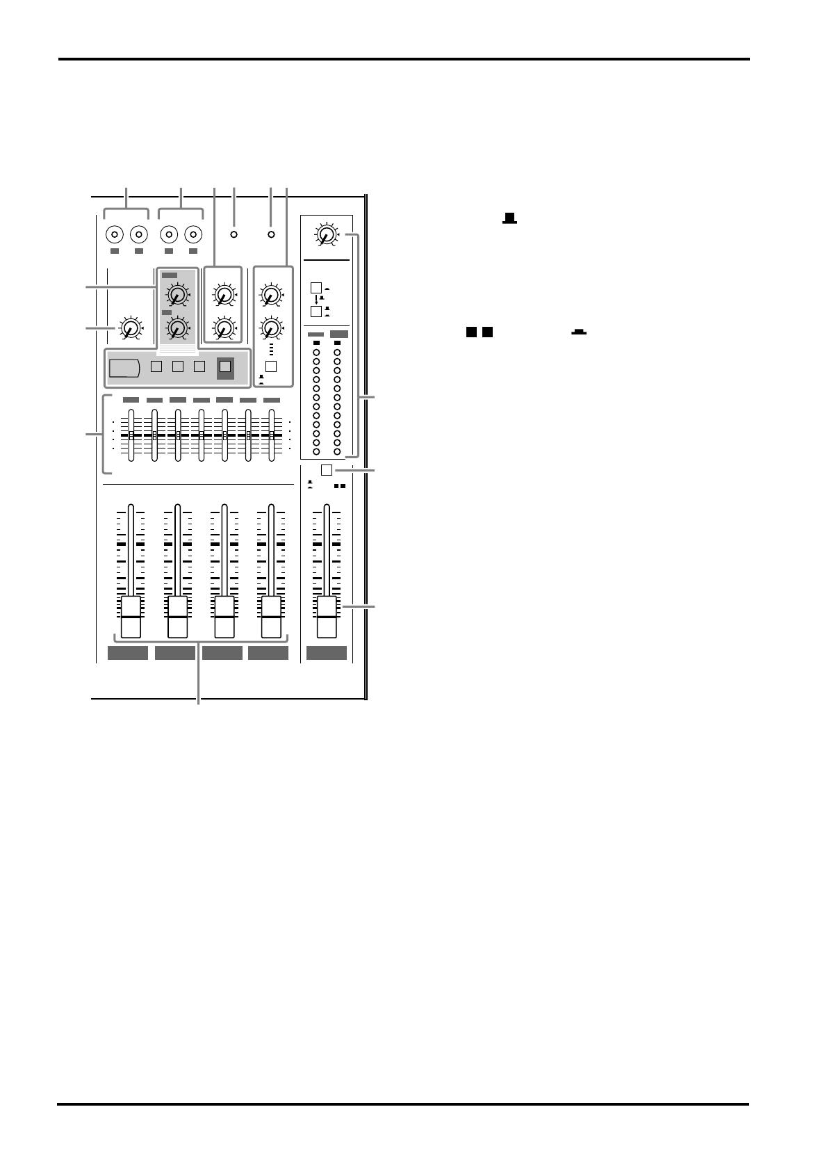
Channel control section
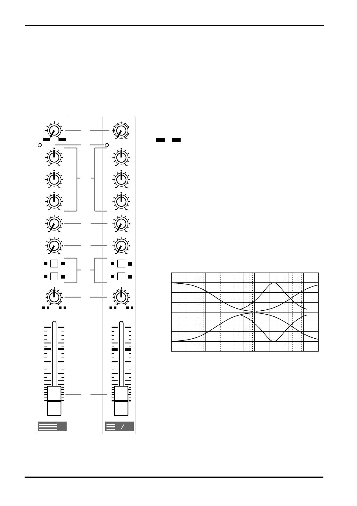
1
GAIN control
Use this knob to adjust the sensitivity according to the input sig-
nal level, so that the input level is appropriate.
For the best balance of S/N ratio and dynamic range, adjust this
knob so that the peak indicator
2
lights occasionally.
~ indicates the MIC input adjustment level, and –34~
+10 indicates the LINE input adjustment level.
2
PEAK indicator
This detects the peak level post EQ.
The indicator will light red 3dB before clipping, warning that
clipping level is near.
3
Equalizer
This provides
±
15dB of control over the high, mid and low
ranges at the following center frequencies.
HIGH : 12kHz (shelving)
MID : 2.5kHz (peaking)
LOW : 80Hz (shelving)
The frequency response will be flat when the knob is in the “
▼
”
position.
4
MONI (monitor) control
This knob controls the level of the signal that is sent from each
channel to the MONI bus.
Since this control is placed before the channel fader, it controls
the level independently from the channel fader setting.
5
EFFECT control
This knob controls the level of the signal that is sent from each
channel to the EFFECT bus.
Since this control is placed after the channel fader, the signal
level will be affected by the channel fader setting.
9
10
2413
10
5
0
5
10
15
20
30
40
00
1
2
3
4
+10
-34
GAIN
HIGH
MID
LOW
MONI
EFFECT
BAL
PEAK
0
10
0
10
1
2413
1
2
3
4
10
5
0
5
10
15
20
30
40
00
-16
-60
+10
-34
PAN
GAIN
HIGH
MID
LOW
MONI
EFFECT
PEAK
0
10
0
10
Channels 1~8
(monaural)
Channels 9~12
(stereo)
1
2
3
4
5
6
7
8
-15
+15
-15
+15
-15
+15
-15
+15
-15
+15
-15
+15
–60
–16
Response [dB]
+5
+10
+15
–15
–10
–5
0
Frequency [Hz]
10k1k100 20k20
+20
–20
Channel control section
3
MX12/4—Owner’s Manual
6
Group select switches
These switches send the signal of each channel to GROUP buses 1~4.
When the / switches are on (pressed in), the signal will be sent to the GROUP buses 1/2.
When the / switches are on (pressed in), the signal will be sent to the GROUP buses 3/4.
When both switches are on, the signal will be sent to GROUP buses 1/2 and 3/4.
7
PAN (panpot) control
BAL (balance) control
The PAN knobs (channels 1~8) set the stereo position of the signal that is sent to the GROUP
buses 1/2 or 3/4.
The BAL knobs (channels 9~12) set the balance between the left/right channels, and assign
the signals received at inputs 9 L (MONO) and 11 L (MONO) to the GROUP buses 1/3, and
the signals received at inputs 10 R and 12 R to the GROUP buses 2/4.
If signals are input monaurally to input 9 L (MONO) or 11 L (MONO), the same signal will
be sent to groups 1~4.
8
Channel fader
This controls the output level of the input channel signal, adjusting the volume balance
between channels. The faders of unused channels should be lowered.
1 2
3 4
EFFECT
MONI
EFFECT
MONI
PEAK
PEAK
PHANTOM
GAIN
LOW
MID
HIGH
BAL
R
L(MONO)
EQHA
INPUT
9/10
11/12
HA EQ
LOW
MID
EQ
GAIN
HA
HIGH
PAN
PAD
MIC
LINE
INPUT
5-8
EFFECT
MONI
MONI
EFFECT
INPUT
1-4
LINE
MIC
INS
I/O
PAD
PHANTOM
MASTER
GROUP
4321
PAN
HIGH
HA
GAIN
EQ
MID
LOW
PEAK
4
Front panel
MX12/4—Owner’s Manual
Master control section
1
ST OUT output select switch
This switch selects the signal which is output via the
ST
fader from the ST OUTPUT jacks.
ST position ( )
The ST OUTPUT jacks will output the ST bus signal
(the post-fader signals of groups 1~4, the input signals
from the RTN jacks, the return signal from the internal
digital effect, and the input signal from the TAPE IN
jacks).
GROUP position ( )
The ST OUTPUT jacks will output the pre-fader sig-
nals of groups 3/4.
When this position is selected, the input channel sig-
nals will be sent directly to the ST bus without passing
through the group buses 1~4. This setting lets you use
the MX12/4 as a simple 12 in-2 out mixer.
2
ST master fader
This fader adjusts the final combined level of all chan-
nels, and sends the signal to the ST OUTPUT jacks.
The meters allow you to view the L and R output levels.
3
GROUP 1~4 faders
These faders adjust the signal levels of groups 1~4, and
send their signals to GROUP OUTPUT 1~4 jacks
respectively and to the ST bus.
Groups 1 and 3 are sent to ST L, and groups 2 and 4 are
sent to ST R.
4
Stereo graphic EQ
This is a stereo 7-band graphic equalizer that adjust the
tonal quality of the signal output to the ST OUTPUT
jacks.
A
±
12dB boost or cut is provided at each of the fre-
quency bands 125, 250, 500, 1k, 2k, 4k, and 8kHz.
5
TAPE IN jacks
These are line level input jacks to which an external DAT recorder or CD player etc. can be
connected for monitoring. The signals which are input here are sent to the ST bus. The input
levels are adjusted by the TAPE IN ST control (
9
). Depending on the setting of the C-R•
PHONES select switch (
D
), the signal can also be monitored directly from the C-R OUT jack.
6
REC OUT jacks
These jacks allow an external DAT recorder or cassette recorder to be connected, to record the
same signal as the ST OUTPUT jacks.
The signals that are output from these jacks are not affected by the settings of the ST master
fader or the graphic EQ. Make recording level adjustments on the recording device.
7
PHANTOM indicator
This indicator will light when the PHANTOM switch (rear panel
2
) is on.
8
POWER indicator
This indicator will light when the MX12/4’s power is on.
ST
GROUP 4
GROUP 3
GROUP 2
GROUP 1
010
3
4
ST
GROUP
EFFECT
MONI2
METER
C-R•PHONES
TAPE IN
ST
EFFECT
⁄ MONI
C-R•PHONES
010
010
010
010
010
010
ST
MONI
SEND
RTN
MONI 1MONI
EFFECT ⁄ MONI 2
ST
TAPE IN
ST
010
LR
L
R
TAPE IN
REC OUT
PHANTOM POWER
ON
VOCAL
L HALL S HALL
DIGITAL
EFFECT
MONI 1
EFFECT
/ MONI 2
L
R
PEAK
+5
+3
+1
0
-1
-3
-5
-7
-10
-15
-20
ST GRAPHIC EQUALIZER
10
5
0
5
10
15
20
30
40
00
10
5
0
5
10
15
20
30
40
00
10
5
0
5
10
15
20
30
40
00
10
5
0
5
10
15
20
30
40
00
10
5
0
5
10
15
20
30
40
00
+12
-12
6
0
6
+12
-12
6
0
6
8k4k
2k
1k
500
250
125
3
AB
1
2
4
5
6
78
9
0
C
3 4

Master control section
5
MX12/4—Owner’s Manual
9
ST control
This knob adjusts the monitor level of the external device (tape deck etc.) connected to the
TAPE IN jacks (
5
).
0
DIGITAL EFFECT
MONI control
—This knob adjusts the level of the return signal which is sent from the inter—
nal digital effect to the MONI bus.
ST control
—This knob adjusts the level of the return signal which is sent from the internal
digital effect to the ST bus.
Effect select switches
—These switches select the effect type for the internal digital effect:
VOCAL, L HALL (large hall), or S HALL (small hall).
Do not attempt to turn off all switches or to simultaneously press two or more switches, since
this will cause malfunctions.
ON switch
—This switch turns the internal digital effect on/off. When this is off, no signal will
be sent from the internal digital effect.
A
RTN
MONI control
—This knob adjusts the level of the signal that is sent from the RTN jacks to the
MONI bus.
ST control
—This knob adjusts the level of the signal that is sent from the RTN jacks to the ST
bus. If a signal is input only to the RTN L (MONO) jack, the same signal will be sent to the ST
bus L and R.
B
SEND
MONI 1 control
—This knob adjusts the level of the MONI bus signal that is output to the
SEND MONI 1 jack.
EFFECT/MONI 2 control
—This knob adjusts the level of the EFFECT bus or MONI bus sig-
nal that is output to the SEND EFFECT/MONI 2 jack.
The level of the signal that is sent from the EFFECT bus to the internal digital effect is fixed,
and cannot be adjusted (nor by this control).
Output select switch
—This switch selects the signal that will be output to the SEND EFFECT/
MONI 2 jack.
EFFECT position
()
—The EFFECT bus signal will be output.
MONI 2 position
()
—The MONI bus signal will be output.
C
C-R•PHONES
Here you can select and adjust the signal that is output to the C-R OUT jack and the PHONES
jack.
C-R•PHONES control
— This knob adjusts the output level to the C-R OUT jack and
PHONES jack.
Output select switch
—These switches select the output signal for the C-R OUT jack and
PHONES jack.
•
When the upper switch is on (TAPE IN ), the signal from the TAPE IN
jacks will be output.
•
When the upper switch is off ( )
• When the lower switch is off (ST ), the same signal as the ST OUT—
PUT jacks will be output.
• When the lower switch is on (EFFECT/MONI ), the signal of the
SEND MONI 1 jack will be sent to the L channel, and the SEND
EFFECT/MONI 2 signal will be sent to the R channel.
Meter
—The LEDs indicate the output level before the C-R•PHONES control. A position of 0
indicates nominal level, and when clipping level is approached, PEAK will light red as a warn-
ing.
6
Front panel
MX12/4—Owner’s Manual
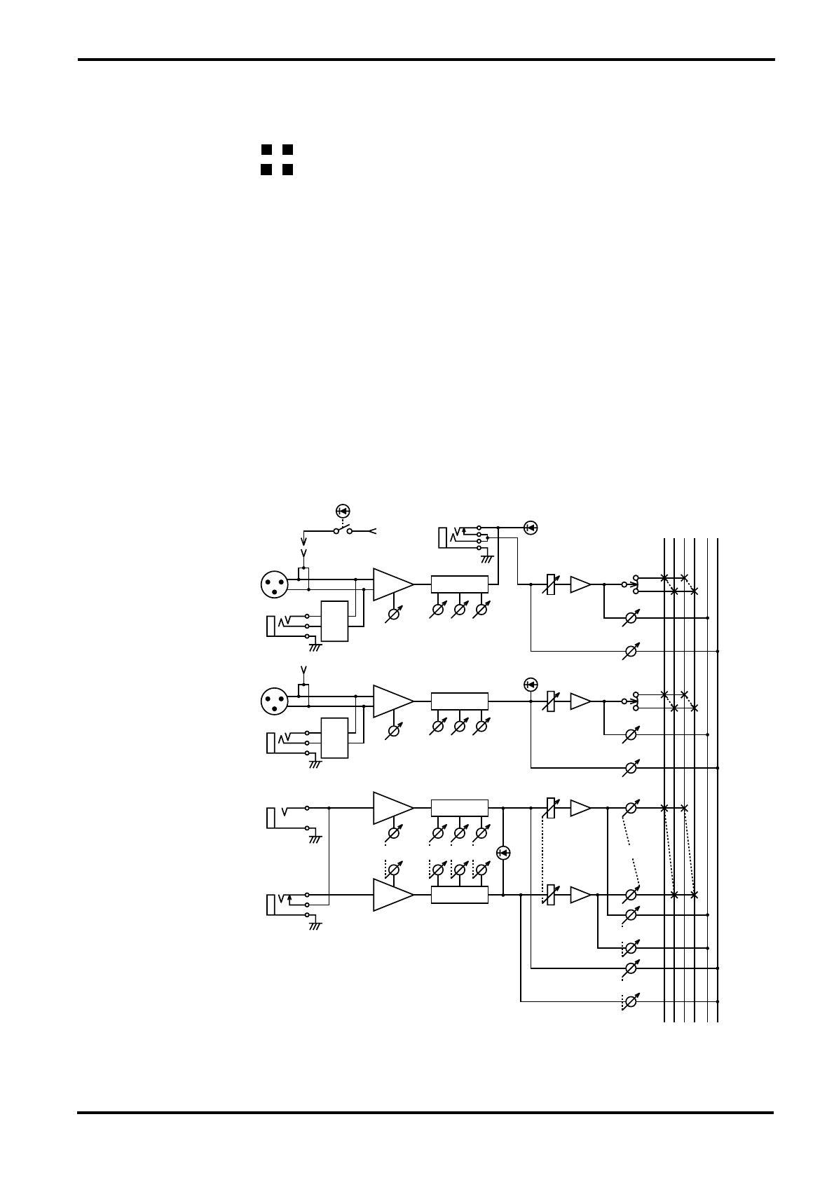
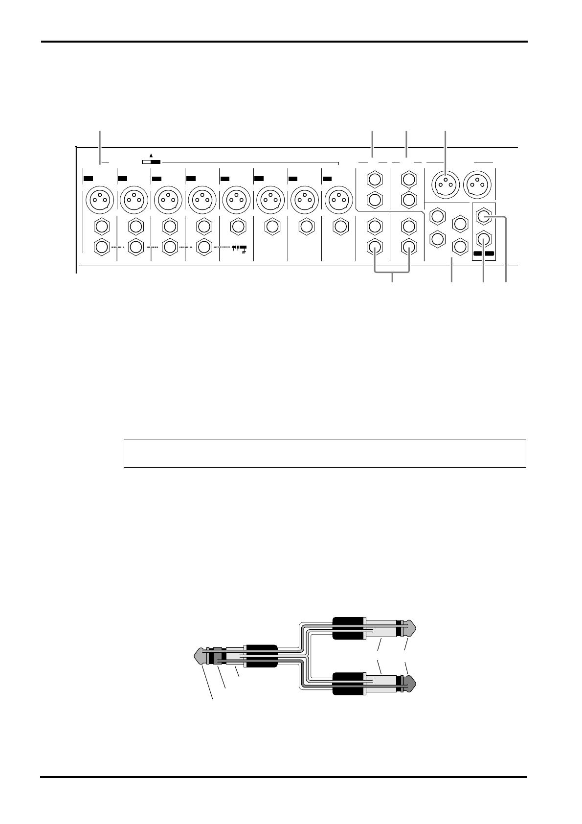
Connector section
1
INPUT
MIC (1~8)
—These are balanced XLR type mic input jacks (1: ground, 2: hot, 3: cold).
These inputs are compatible with 50~600
Ω
microphones.
LINE (1~8)
—These are balanced TRS phone type line input jacks (T: hot, R: cold, S:
ground).
These inputs are compatible with 600 ohm line level devices.
It is also possible to connect unbalanced phone plugs, but noise may enter the signal if the
cables are long or if the location is susceptible to electromagnetic interference.
INS I/O 1~4
—These are input/output jacks placed between the equalizer and fader of input
channels 1~4.
The nominal input level/impedance is 0dB/600
Ω
, and the nominal output level/impedance is
0dB/10k
Ω
.
Devices such as graphic equalizers, compressors or noise filters can be connected here.
The INS I/O jacks provide bi-directional connections using TRS (tip, ring, sleeve) phone
jacks. These connections require a special insertion cable such as shown in the following dia-
gram.
Note:
It is not possible to connect both the MIC INPUT jack and the LINE INPUT jack for
an individual input channel. Only one or the other jack may be used.
PHONES
L(MONO)
R
C-R OUT
ST OUTPUT
RTN SEND
GROUP
OUTPUTINPUT INPUT
L
(MONO)
R
L
(MONO)
R
EFFECT MONI
2
1
2
3
4
MONI
1
PHANTOM +48V
ON
MIC
INPUT INPUT INPUT INPUT INPUT INPUT INPUT INPUT
LINE LINELINE LINE LINE LINE LINE LINE
INS
I ⁄ O
INS
I ⁄ O
INS
I ⁄ O
INS
I ⁄ O
INSERT I/O
OUT IN
9
10
11
12
12345678
MIC
MIC
MIC
MIC
MIC
MIC MIC
L
R
OFF
2135
4687
to the input jack of
the external processor
to the output jack of
the external processor
to the INS I/O jack
Tip
Tip
Ring
Sleeve
Sleeve

Connector section 7
MX12/4—Owner’s Manual
2 RTN L (MONO), R
These are unbalanced phone type line input jacks, with a nominal input level and impedance
of +4dB/600Ω.
The signals which are input from these jacks are sent to the ST bus and the MONI bus.
Normally, these jacks are used to receive the return signal from an external effect device such
as reverb or delay, but they can also be used as auxiliary stereo inputs. If only the L (MONO)
jack is connected, the same signal will be sent both to the R jack and L jack, for monaural
input.
3 SEND MONI 1, EFFECT/MONI 2
These are unbalanced phone type output jacks. The nominal input level and impedance are
+4dB/600Ω.
The MONI 1 jack outputs the MONI bus signal, and the EFFECT/MONI 2 jack outputs the
signal of the EFFECT bus or MONI bus. These are used to send signals to an external effect
unit or to a monitor system such as a cue box.
4 INPUT 9~12
These are unbalanced phone type stereo line input jacks, compatible with 600Ω line level
devices.
If only the L (MONO) jack is connected, the same signal will be sent both to the L and R jacks,
for monaural input. In this case, the group select switch (channel control section 6) will send
the same signal to the group buses 1/2 or 3/4.
5 ST OUTPUT (L, R)
These are balanced XLR type output jacks with a nominal output/impedance of +4dB/600Ω.
They provide stereo output of the mixed signal, and are normally connected to a power amp
etc. which drives the main speakers.
These outputs can also be used in order to record the signal at a level adjusted by the ST fader.
6 GROUP OUTPUT 1~4
These are unbalanced phone type output jacks which output the signals of group buses 1~4,
with a nominal output/impedance of +4dB/600Ω. Normally these are connected to the input
jacks of an MTR or an external mixer.
7 C-R OUT
This is a stereo phone type output jack for connection to a monitor system etc., with a nomi-
nal output/impedance of +4dB/10kΩ.
The source monitored by this jack is selected by the C-R•PHONES output select switch (mas-
ter control section C).
8 PHONES
This is a stereo phone type output jack for connecting a set of headphones.
The source monitored by the headphones is selected by the C-R•PHONES output select
switch (master control section C).
Note: An insertion cable can also be used when connecting this jack to a stereo monitor sys-
tem.
8 Rear panel
MX12/4—Owner’s Manual
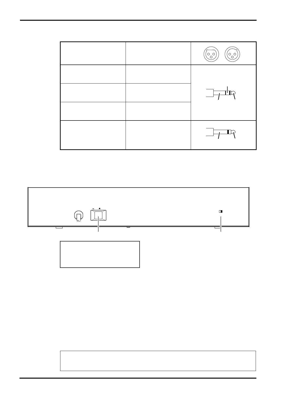
Connector polarity
Rear panel
1 POWER switch
When this is on, power is applied to the unit.
When turning off the power, the rule for audio equipment is to turn off devices in the order of
their closeness to the speakers (normally beginning with the power amp).
2 PHANTOM switch
This switch turns the phantom power on/off for all channels 1~8.
Use this when you are using condenser microphones.
When this switch is on, +48V DC will be supplied to pins 2 and 3 of all XLR type MIC INPUT
connectors.
If you do not require phantom power, be sure to set this in the OFF position.
MIC INPUT
ST OUTPUT
Pin 1: ground
Pin 2: hot (+)
Pin 3: cold (–)
LINE Input
Tip: hot (+)
Ring: cold (–)
Sleeve: ground
INS I/O
Tip: Output
Ring: Input
Sleeve: ground
C-R OUT
Tip: L
Ring: R
Sleeve: ground
Stereo Input
RTN
GROUP OUTPUT
SEND MONI1
SEND EFFECT/MONI2
Tip: hot
Sleeve: ground
Note: Although it will not cause problems to connect balanced dynamic microphones or line
level devices with this switch turned on, connecting unbalanced devices or devices for which
the center of the transformer is ungrounded may cause hum or malfunction.
PHANTOM MASTER
CH1 ~ 8
ON OFF
(+48V)
POWER
ON ⁄ OFF
21
Phantom Power Warning
To prevent hazard or damage, connect
only microphones and cables that
conform to the IEC268-15A standard.
10 Specifications
MX12/4—Owner’s Manual
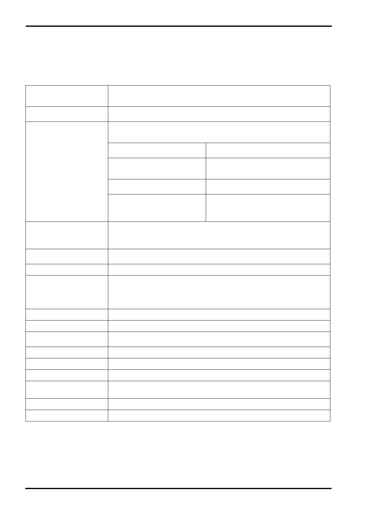
Specifications
■ General specifications
Frequency response
20Hz~20kHz+1dB, –2dB @+4dB
Input Gain control at minimum level
Total harmonic distortion
<0.1%@+14dB 20Hz~20kHz
Hum and noise
(Rs=150Ω, 20Hz~20kHz)
–128dB equivalent input noise
–95dB residual output noise
–87dB (ST OUT/GROUP OUT)
ST master/GROUP fader at nominal level and all
channel fader at minimum.
–64dB (68dB S/N)
(ST OUT/GROUP OUT)
ST master/GROUP fader at nominal level
One channel fader, Gain control: maximum.
Fader: nominal
–80dB (MONITOR1 OUT, EFFECT/
MONITOR2 OUT)
Master level control at nominal level and all channel
level controls at minimum.
–64dB (68dB S/N)
(MONITOR1 OUT, EFFECT/MONITOR2
OUT)
Master fader at nominal level
One channel fader, Gain control: maximum.
Fader: nominal
Control level: nominal
Maximum voltage gain
84dB MIC IN to GROUP OUT
58dB LINE IN to GROUP OUT
90dB MIC IN to EFFECT/MONITOR2 OUT
80dB MIC IN to MONITOR1 OUT
Crosstalk at 1kHz
70dB adjacent input
70dB input to output
Gain control 44dB variable
Input channel equalization
±15dB Maximum
HIGH 12kHz shelving
MID LOW 2.5kHz peaking
LOW 80Hz shelving
* Turn over/Roll off frequency of shelving: 3dB below maximum variable level
Meters 12 points LED
Channel peak indicators An indicator for each channel turns on when the pre-channel fader signal is 3dB below clipping.
Graphic equalizer
7 bands (125, 250, 500, 1k, 2k, 4k, 8kHz)
±12 Maximum
Internal digital effect 3 types
Phantom power +48V (balanced)
Option Rack Mount Kit RK124
Power supply/
Power consumption
USA and Canadian 120V AC 60Hz, 30W
General 230V AC 50Hz, 40W
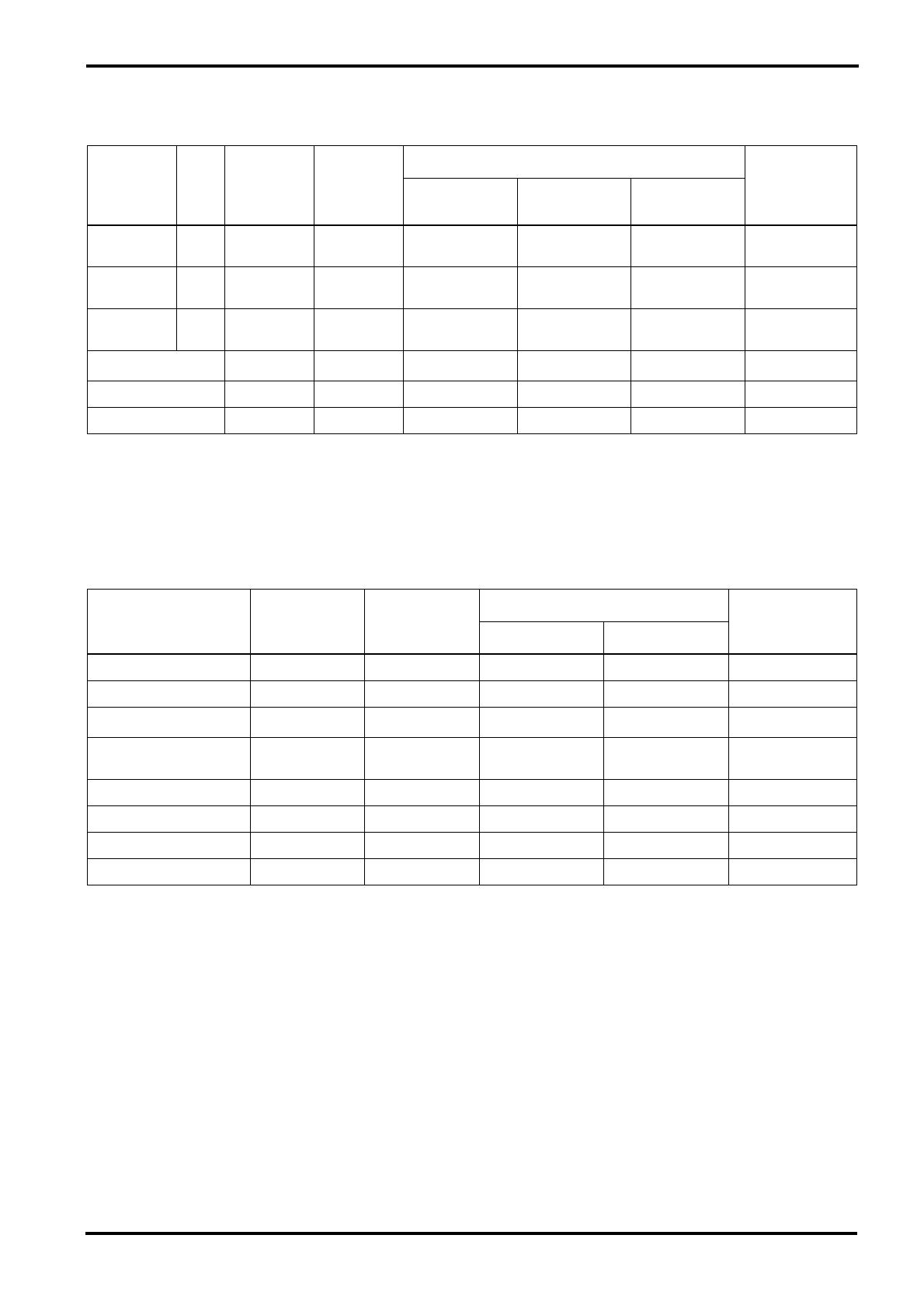
Dimensions (WxHxD) 436.2×83.1×401.2mm
Weight 7.0kg
Input specifications 11
MX12/4—Owner’s Manual
■ Input specifications
■ Output specifications
1. Sensitivity is the lowest level that will produce an output of +4 dB (1.23V) or the nominal output level when the unit is set to maximum gain.
2. XLR type connectors and phone jacks (TRS) (T=Hot, R=Cold, S=Gnd) are balanced.
3. Phone jacks are unbalanced.
4. Phone jacks (I/O) (T=OUT, R=IN, S=GND) are unbalanced.
• 0dB=0.775Vrms, 0dBV=1Vrms
1. XLR type connectors are balanced.
2. Phone jacks are unbalanced.
3. ST phone jacks (T=L, R=R, S=GND) are unbalanced.
4. Phone jacks (I/O) (T=OUT, R=IN, S-GND) are unbalansed.
• 0dB=0.775Vrms, 0dBV=1Vrms
Input
connectors
Gain
trim
Input
impedance
Nominal
impedance
Input level
Connector type
Sensitivity
1
Nominal level
Max. before
clipping
MIC INPUT
(1-8)
MAX
MIN
5kΩ 50~600Ω mic
–90dB (24.5µV)
–36dB (12.3mV)
–60dB (775µV)
–16dB (123mV)
–40dB (7.75mV)
+4dB (1.23V)
XLR3-31 type
2
LINE INPUT
(1-8)
MAX
MIN
50kΩ 600Ω line
–64dB (490µV)
–10dB (245mV)
–34dB (15.5mV)
+10dB (2.45V)
–14dB (155mV)
+30dB (24.5V)
Phone jack (TRS)
2
ST INPUT
(9-12)
MAX
MIN
10kΩ 600Ω line
–54dB (1.55mV)
–10dB (245mV)
–34dB (15.5mV)
+10dB (2.45V)
–14dB (155mV)
+30dB (24.5V)
Phone jack
3
RTN (L•R) 10kΩ 600Ω line –12dB (195mV) +4dB (1.23V) +20dB (7.75V)
Phone jack
3
TAPE IN (L•R) 10kΩ 600Ω line –26dBV (50.1mV) –10dBV (316mV) +18dBV (7.75V) RCA pin jack
INS I/O (1-4) 10kΩ 600Ω line –20dB (77.5mV) 0dB (775mV) +20dB (7.75V) Phone jack (I/O)
4
Output connector
Output
impedance
Nominal
impedance
Output level
Connector type
Nominal
Max. before clipping
ST OUTPUT (L•R) 150Ω 600Ω Lines +4dB (1.23V) +24dB (12.3V) XLR-3-32 type
1
GROUP OUTPUT (1-4) 75Ω 600Ω Lines +4dB (1.23V) +20dB (7.75V) Phone jack
2
MONITOR1 OUT 75Ω 600Ω Lines +4dB (1.23V) +20dB (7.75V)
Phone jack
2
SEND MONI1,
EFFECT/MONI2
75Ω 600Ω Lines +4dB (1.23V) +20dB (7.75V)
Phone jack
2
C-R OUT 470Ω 10kΩ Lines +4dB (1.23V) +20dB (7.75V) ST phone jack
3
REC OUT (L•R) 600Ω 10kΩ Lines –10dBV (316mV) +10dBV (3.16V) RCA pin jack
PHONES 100Ω 40Ω Phones 3mW 100mW ST phone jack
INS I/O (1-4) 600Ω 10kΩ Lines 0dB (775mV) +20dB (7.75V) Phone jack
4
12 Specifications
MX12/4—Owner’s Manual
■ Dimensions
Specifications are subject to change without prior notice.
W:436.2
310
H:83.1
3.2
76.6
D:401.2
13.5
320
Units mm
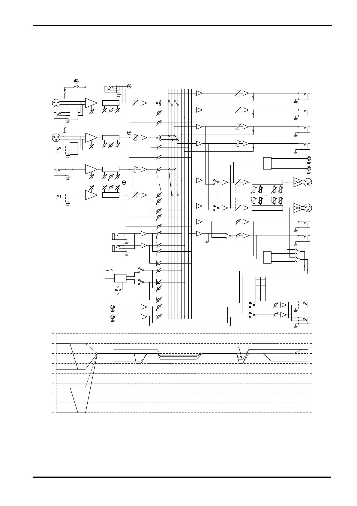
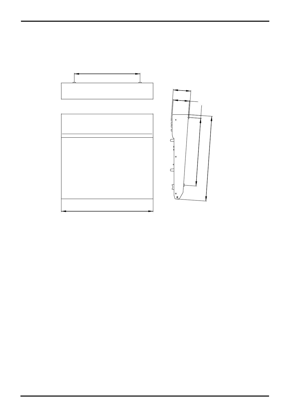
Block and Level diagram 13
MX12/4—Owner’s Manual
■ Block and Level diagram
EFFECT
EFFECT
GROUP,EFFECT,MONITOR
EFFECT,MONITOR
GROUP,ST
EFFECT,MONITOR,TAPE
(from EFFECT)
7 BAND ST GEQ
7 BAND ST GEQ
ST
ST
INS
MONI
ST
REC
ST
TAPE
RTN
MIC
MIC
LINE
LINE
GROUP 3 4
ST
ST
OUTPUT
EFFECT
MONI
MONI
ST
–50
–40
–30
–20
–10
0
10
20 20
10
0
–10
–20
–30
–40
–50
–60–60
EFFECT
/MONI
PEAK
PEAK
PHANTOM
TAPE IN
(to DSP)
ON
S HALL
L HALL
VOCAL
DSP
ST
MONI
RTN
L(MONO)
R
PAD
EFFECT
MONI 2
EFFECT/
MONI 2
MONI 1
SEND
EFFECT/
MONI 2
MONI 1
PAD
REC OU
L
R
R
L
8k4k
250125
ST
C-R.PHONES
C-R OUT
GROUP 4
GROUP 3
4
3
GROUP
OUTPUT
2
1
GROUP 2
ST
GAIN
LOW
MID HIGH
BAL
R
L(MONO)
EQHA
INPUT
9/10
11/12
HA EQ
LOW
MID
EQ
GAIN
HA
HIGH
PAN
PAD
MIC
LINE
INPUT
5-8
EFFECT
MONI
MONI
EFFECT
INPUT
1-4
LINE
MIC
INS
I/O
PAD
PHANTOM
MASTER
GROUP ST
TAPE IN
PHONES
R
L
GROUP 1
RL4321
PAN
HIGH
HA
GAIN
EQ
MID
LOW
PEAK

VV68420 R0 1 IP YAMAHA CORPORATION
P.O.Box 1, Hamamatsu, Japan
96 09 700 NP Printed in Taiwan
Руководстве по эксплуатации Yamaha MX12/4 — вам приходилось его терять? Поскольку вы попали сюда, наверняка с вами это случилось. Но вы не единственный человек, сталкивающийся с проблемами с хранением руководства по эксплуатации всех домашних устройств. Ниже несколько советов, касающихся того, зачем собирать руководства по эксплуатации.
Руководстве по эксплуатации Yamaha MX12/4 это определенный вид технической документации, являющейся неразлучным элементом каждого устройства, которое мы приобретаем. Они отличаются между собой количеством информации, которую можно найти на тему данного устройства: напр. Yamaha MX12/4. Конечно же, если производитель считает что необходимо передать нам большее количество информации, касающейся устройства Yamaha MX12/4, то стоит ее хоть раз прочитать — в начале, сразу же после покупки данной вещи. Однако мы считаем, что инструкции должны заключать самую важную, наиболее необходимую информацию о Yamaha MX12/4, так, чтобы не отнимать желания пользователя прочесть ее уже в самом начале. Несомненно, если устройство Yamaha MX12/4 имеет много продвинутых функций, неизбежно большое количество информации в содержании этого документа.
Które из информации в инструкции Yamaha MX12/4 необходимо обязательно прочитать?
- Информацию, касающуюся правильного использования и ухода за устройством Yamaha MX12/4 — нам необходимо ознакомиться с основными правилами, чтобы в случае проблем с устройством сервисный центр не отказал нам в гарантийном обслуживании, из-за неправильного использования
- Информация, касающаяся самых частых проблем с Yamaha MX12/4 и способы их решения
- Информация, касающаяся гарантии устройства Yamaha MX12/4 и ближайших сервисных центров, способных починить устройство в соответствии с рекомендациям производителя Yamaha
Как хранить инструкции дома?
Хорошей идеей является предназначение одного ящика, в котором бы хранилась инструкция Yamaha MX12/4 а также всех других домашних устройств которыми мы пользуемся. Тогда значительно легче вам будет ее найти, чем искать в родных коробках, которые наверняка уже выбросили вы, или другие домочадцы. Раз в год достаточно просмотреть ящик и выбросить инструкции, которые касаются устройств, которыми вы уже не пользуетесь. Таким образом вы избежите хранения ненужных документов, а останутся только актуальные. Вы можете также скачать и распечатать инструкцию Yamaha MX12/4 чтобы разместить ее в своем ящике.
Похожие инструкции
Краткое содержание страницы № 1
MIXING CONSOLE
•
•
•
•
•
•
•
•
J
Краткое содержание страницы № 2
!
Краткое содержание страницы № 3
!
Краткое содержание страницы № 4
1 GAIN GAIN 2 1 +10 -34 -34 +10 -16 -60 –60 –16 PEAK PEAK 2 HIGH HIGH +15 2 -15 -15 +15 MID MID 3 +15 +15 -15 -15 LOW LOW 3 -15 +15 -15 +15 MONI MONI 4 10 10 0 0 EFFECT EFFECT 5 10 0 10 0 1 2 1 2 6 3 4 3 4 +20 PAN BAL +15 7 +10 13 24 13 24 +5 0 10 10 –5 5 5 –10 0 0 –15 5 5 –20 20 100 1k 10k 20k 10 10 Frequency [Hz] 15 15 20 20 30 30 4 40 40 8 00 00 9 1 10 Respon
Краткое содержание страницы № 5
5 6 1 2 3 4 7 8 PHANTOM PEAK GROUP 1 2 3 4 INS I/O PHANTOM MASTER MIC HA EQ PAN INPUT 1-4 PAD LINE GAIN EFFECT MONI PEAK HA EQ MIC PAN INPUT 5-8 PAD LINE GAIN EFFECT MONI HA EQ L(MONO) INPUT MID BAL GAIN LOW HIGH 9/10 PEAK 11/12 HA EQ R EFFECT MONI LOW LOW MID MID HIGH HIGH EFFECT MONI
Краткое содержание страницы № 6
1 5 6AB 78 PHANTOM POWER 010 R LR L C-R•PHONES TAPE IN REC OUT METER RTN SEND C-R•PHONES MONI MONI MONI 1 TAPE IN 0 TAPE IN 010 010 010 ST EFFECT ⁄ MONI 2 ST EFFECT ST ST ⁄ MONI 9 EFFECT MONI 1 / MONI 2 010 010 010 010 L R 3 4 PEAK +5 DIGITAL +3 EFFECT L HALL S HALL VOCAL ON EFFECT +1 MONI2 0 -1 125 250 500 1k 2k 4k 8k C -3 -5 +12 +12 -7 6 6 -10 0 0 4 -15 6 6 -20 -12 -12 2 ST GRAPHIC EQUALIZER 1 ST 3 4 GROUP
Краткое содержание страницы № 7
8 9 5 0 A B C • •
Краткое содержание страницы № 8
13 25 PHANTOM +48V OFF ON RTN SEND ST OUTPUT L(MONO) INPUT INPUT INPUT INPUT INPUT INPUT INPUT INPUT MONI 1 MIC MIC MIC MIC MIC MIC MIC MIC EFFECT MONI R 2 L R 1 L(MONO) L(MONO) LINE LINE LINE LINE LINE LINE LINE LINE 9 11 3 C-R OUT 2 INS INS INS INS R R I ⁄ O I ⁄ O I ⁄ O I ⁄ O 10 12 4 INSERT I/O OUT IN PHONES GROUP 1 2 3 4 5 678 INPUT INPUT OUTPUT 4687 1 2
Краткое содержание страницы № 9
3 4 6 5 6 7 C 8 C 2 1 1 2 3 3 Ring Sleeve Tip Sleeve Tip
Краткое содержание страницы № 10
POWER PHANTOM MASTER ON ⁄ OFF CH1 ~ 8 ON OFF (+48V) 1 2 1 2
Краткое содержание страницы № 11
88 C-R OUT INS I/O ST OUTPUT PHONES TAPE IN MIXING CONSOLE REC OUT GROUP OUTPUT SEND 88 RTN INPUT 1 2 3 4 3 4 5 1 2 3 4
Краткое содержание страницы № 12
Ω Ω Ω Ω
Краткое содержание страницы № 13
H:83.1 76.6 3.2 Ω µ µ Ω Ω Ω µ Ω Ω Ω Ω Ω Ω Ω Ω • Ω Ω Ω Ω Ω Ω Ω Ω Ω Ω Ω Ω Ω Ω Ω Ω • 310 W:436.2 320 13.5 D:401.2
Краткое содержание страницы № 14
PHANTOM PEAK GROUP ST INS 1 2 3 4 L R I/O PHANTOM MASTER 1 GROUP 1 MIC HA EQ INPUT PAN 1-4 2 PAD LINE GROUP 2 GAIN EFFECT GROUP OUTPUT MONI PEAK 3 GROUP 3 MIC HA EQ INPUT PAN 5-8 4 PAD GROUP 4 LINE GAIN EFFECT L MONI PAD REC OUT HA EQ R L(MONO) PEAK INPUT BAL GAIN MID HIGH 7 BAND ST GEQ L LOW 9/10 11/12 ST HA EQ ST 125 250 4k 8k OUTPUT R ST EFFECT 7 BAND ST GEQ R GROUP 3 4 MONI MONI 1 MONI 1 EFFECT SEND L(MONO) EFFECT/ MONI 2 ST EFFECT/ MONI 2 RTN MONI 2 (to DSP) R ST PAD MONI EFFECT (from EFF
Краткое содержание страницы № 15
Краткое содержание страницы № 16
VU86950 R1 1 IP 16 97 11 1000 NP Printed in Taiwan