
PDF
2
3
2.
3.
4
38
38
38
38
38
41
42
42
44
45
46
46
46
49
49
50
50
52
54
55
57
57
58
58
58
59
59
59
59
59
60
62
62
63
64
65
65
67
67
67
67
67
70
71
71
73
74
75
4.
75
75
78
78
79
79
81
83
84
86
86
87
87
87
88
88
88
88
89
89
91
91
92
93
94
94
5
5.
6
114
115
115
115
116
116
116
116
116
117
118
119
120
121
121
122
124
124
124
124
124
127
127
128
130
131
132
132
132
134
134
135
135
137
139
140
142
142
143
143
143
144
144
144
144
144
145
147
147
148
6.
7.
152
152
152
152
152
155
155
156
158
158
159
160
160
162
162
163
163
164
167
167
170
170
170
170
171
171
171
171
171
172
173
174
174
175
176
177
177
179
179
179
179
179
182
7
8.
199
199
200
200
200
201
201
201
202
204
204
205
206
207
207
Русский . . . . . . . . . . . . . . . . . . . . . . . . . . . . . . . . . . . . . . . . . . . . . . . . . . . . . . . . 209
Общая информация . . . . . . . . . . . . . . . . . . . . . . . . . . . . . . . . . . . . . . . . . . . . . . . . . . . . . .
Квалификация пользователя . . . . . . . . . . . . . . . . . . . . . . . . . . . . . . . . . . . . . . . . . . . . . .
Раздел безопасности . . . . . . . . . . . . . . . . . . . . . . . . . . . . . . . . . . . . . . . . . . . . . . . . . . . . .
Значение сигнальных слов . . . . . . . . . . . . . . . . . . . . . . . . . . . . . . . . . . . . . . . . . . . .
Общие правила техники безопасности . . . . . . . . . . . . . . . . . . . . . . . . . . . . . . . . . .
Назначение . . . . . . . . . . . . . . . . . . . . . . . . . . . . . . . . . . . . . . . . . . . . . . . . . . . . . . . . .
Отказ от ответственности . . . . . . . . . . . . . . . . . . . . . . . . . . . . . . . . . . . . . . . . . . . . .
Пульт управления: названия и функции . . . . . . . . . . . . . . . . . . . . . . . . . . . . . . . . . . . . .
Установка . . . . . . . . . . . . . . . . . . . . . . . . . . . . . . . . . . . . . . . . . . . . . . . . . . . . . . . . . . . . . . .
Условия монтажа . . . . . . . . . . . . . . . . . . . . . . . . . . . . . . . . . . . . . . . . . . . . . . . . . . . .
Снятие и повторная установка крышек . . . . . . . . . . . . . . . . . . . . . . . . . . . . . . . . . .
Электрический монтаж. . . . . . . . . . . . . . . . . . . . . . . . . . . . . . . . . . . . . . . . . . . . . . . . . . . .
Стандартная схема соединений. . . . . . . . . . . . . . . . . . . . . . . . . . . . . . . . . . . . . . . .
Выбор провода . . . . . . . . . . . . . . . . . . . . . . . . . . . . . . . . . . . . . . . . . . . . . . . . . . . . . .
Сечения проводов и моменты затяжки цепи управления. . . . . . . . . . . . . . . . . . .
8
183
183
186
186
187
188
188
190
191
191
191
193
196
196
199
199
209
209
209
209
209
213
213
214
217
217
218
218
219
221
222
Запуск привода . . . . . . . . . . . . . . . . . . . . . . . . . . . . . . . . . . . . . . . . . . . . . . . . . . . . . . . . . .
Настройка привода с использованием режима общего назначения . . . . . . . . .
Параметры привода . . . . . . . . . . . . . . . . . . . . . . . . . . . . . . . . . . . . . . . . . . . . . . . . . . . . . .
Поиск и устранение неисправностей . . . . . . . . . . . . . . . . . . . . . . . . . . . . . . . . . . . . . . . .
Порядок сброса отказа. . . . . . . . . . . . . . . . . . . . . . . . . . . . . . . . . . . . . . . . . . . . . . . .
Утилизация . . . . . . . . . . . . . . . . . . . . . . . . . . . . . . . . . . . . . . . . . . . . . . . . . . . . . . . . . . . . .
Инструкции по утилизации . . . . . . . . . . . . . . . . . . . . . . . . . . . . . . . . . . . . . . . . . . . .
Директива по утилизации отходов производства электрического и
электронного оборудования . . . . . . . . . . . . . . . . . . . . . . . . . . . . . . . . . . . . . . . . . . .
Европейские стандарты. . . . . . . . . . . . . . . . . . . . . . . . . . . . . . . . . . . . . . . . . . . . . . . . . . .
Соответствие директиве CE по низковольтному оборудованию . . . . . . . . . . . . .
Область использования. . . . . . . . . . . . . . . . . . . . . . . . . . . . . . . . . . . . . . . . . . . . . . .
Подключение предохранителя со стороны входов (первичная сторона) . . . . .
Директива по электромагнитной совместимости . . . . . . . . . . . . . . . . . . . . . . . . .
Выбор провода . . . . . . . . . . . . . . . . . . . . . . . . . . . . . . . . . . . . . . . . . . . . . . . . . . . . . .
Монтаж привода в соответствии с правилами Директивы по
электромагнитной совместимости . . . . . . . . . . . . . . . . . . . . . . . . . . . . . . . . . . . . . .
Включение внутреннего фильтра электромагнитных помех . . . . . . . . . . . . . . . .
Вход безопасной блокировки . . . . . . . . . . . . . . . . . . . . . . . . . . . . . . . . . . . . . . . . . . . . . .
Характеристики функции безопасной блокировки. . . . . . . . . . . . . . . . . . . . . . . . .
Цепь защитного отключения . . . . . . . . . . . . . . . . . . . . . . . . . . . . . . . . . . . . . . . . . . .
Включение и отключение выходного напряжения привода (“Безопасное
отключение крутящего момента”). . . . . . . . . . . . . . . . . . . . . . . . . . . . . . . . . . . . . . .
Проверка функции защитного отключения. . . . . . . . . . . . . . . . . . . . . . . . . . . . . . .
Функция защитного отключения выхода монитора и дисплей на пульте
оператора. . . . . . . . . . . . . . . . . . . . . . . . . . . . . . . . . . . . . . . . . . . . . . . . . . . . . . . . . . .
9.
223
223
224
227
227
230
230
231
231
232
232
232
232
232
233
234
235
236
237
237
238
239
241
241
241
241
241
244
244
245
247
247
248
249
249
251
251
252
252
253
256
256
259
259
259
259
9
260
260
260
260
260
261
262
263
263
264
265
266
266
268
268
268
278
278
279
279
280
280
280
281
281
281
282
282
283
283
288
291
296
296
300
303
10
1 English
1
English
NOTICE
injury.
11
12
13
Figure 1.1 Keypad
14
Name
A
USB Terminal
RUN Key
B
D
E
F
LO/RE LED
READY LED
15
1 English
Sym
bol
Name
ENTER Key
K
LED Display
REV LED
L
16
Sym
bol
Name
M
N
Indoors
17
1 English
Altitude
18
19
*1
20
*2
*3
*4
*5
Terminal
Recommended
Gauge
mm2 (AWG)
Recommended
Gauge
mm2 (AWG)
0.75
(18)
0.5
(20)
0.25 - 0.5
(24 - 20)
0.75
(18)
0.5
(20)
0.25 - 1.0
(24 - 17)
TB2
MA, MB, MC
Crimp Ferrule
21
1 English
Model
L (mm)
L1 (mm)
φd1 (mm)
φd2 (mm)
0.25 (24)
AI 0.25-8YE
12.5
8
0.8
2.0
0.34 (22)
AI 0.34-8TQ
12.5
8
0.8
2.0
0.5 (20)
14
8
1.1
2.5
menu.
22
User Parameters
Parameter
Name
A2-01
A1-02
A2-02
b1-01
Frequency Reference Selection 1
A2-03
b1-02
A2-04
b1-03
A2-05
C1-01
User Parameters
Parameter
Name
A2-06
C1-02
A2-07
C6-01
A2-08
C6-02
Carrier Frequency Selection
A2-09
d1-01
A2-10
d1-02
A2-11
d1-03
A2-12
d1-04
A2-13
d1-17
Jog Reference
A2-14
E1-01
A2-15
E1-03
A2-16
E1-04
Maximum Output Frequency
A2-17
E1-05
Maximum Output Voltage
A2-18
E1-06
A2-19
E1-09
Minimum Output Frequency
A2-20
E1-13
Base Voltage
A2-21
E2-01
A2-22
E2-04
A2-23
E2-11
A2-24
H4-02
Terminal AM Analog Output Gain
A2-25
L1-01
A2-26
L3-04
23
1 English
Name
A1-02
A1-03
b1-01
b1-02
b1-03
b1-04
C1-01
RUN
C1-02
RUN
C2-01
C2-02
C2-03
C2-04
C6-01
C6-02
24
d1-17
RUN
Jog Reference
d2-01
Name
d2-02
E1-01
E1-04
Maximum Output
Frequency
E1-05
Maximum Output
Voltage
E1-06
E1-09
Minimum Output
Frequency
E2-01
E2-11
H1-01 - H107
H2-01
H2-02
H2-03
H3-01
H3-02
H3-03
RUN
H3-04
RUN
H3-09
H3-10
H3-11
RUN
H3-12
RUN
H3-13
Analog Input
FilterTime Constant
25
1 English
Name
H3-14
H4-01
Terminal AM Analog
Output Select
H4-02
RUN
Terminal AM Analog
Output Gain
H4-03
RUN
Terminal AM Analog
Output Bias
H4-07
L1-01
L1-02
L3-04
■ Fault Reset Procedure
1.
2.
1 English
Name
EF1 - EF7
External Fault
(Terminal Sx)
GF
bb
CrST
EF
oC
oL1
27
1 English
Drive Overload
ov
Overvoltage
PF
oL2
28
SToF
29
EN 61800-3: 2004+A1:2012
•
•
•
•
30
1.
2.
3.
4.
*1
5.
6.
31
32
B001 - B004
2001 - 2006
M3 × 16
0.5 - 0.6
(4.4 - 5.3)
B006 - B012
2010 - 2021
4001 - 4012
M3 × 20
0.5 - 0.6
(4.4 - 5.3)
2030 - 2082
4018 - 4060
M4 × 20
1.2 - 1.5
(10.6 - 13.3)
EMC
33
Input/Output
30 ms or less
PFD = 1.38E-5
PFH = 3.35E-9
Failure probability
N=1
Type B
MTTFD
High
DCavg
Medium
Mission time
10 years
34
1 English
Figure 1.10 Safe Disable Operation
35
3.
36
Keypad
Display
ON
OFF
ON
OFF
(Open)
OFF
ON
OFF
(Open)
ON
OFF
Input 1
(H1-HC)
Input 2
(H2-HC)
MFDO
Terminal
(H2-xx =
21)
MFDO
Terminal
(H2-xx =
121)
OFF
OFF
(Open)
ON
(Close the
circuit)
OFF
(Open)
READY
LED
bit C
bit D
0
0
1
0
ALM/ERR:
Flashing
1
0
0
1
37
2
38
39
40
41
5.
Name
A
Taste RUN
B
42
Symbol
Name
C
D
E
F
LO/RE-LED
43
Symbol
Taste EINGABE
ESC-Taste
I
J
K
LED-Display
REV-LED
L
M
N
44
Lagertemperatur
45
46
47
*1
48
*2
*3
*4
*5
Klemme
0.75
(18)
0.5
(20)
0.25 - 0.5
(24 - 20)
0.75
(18)
0.5
(20)
0.25 - 1.0
(24 - 17)
TB2
MA, MB, MC
49
L (mm)
L1 (mm)
φd1 (mm)
φd2 (mm)
0.25 (24)
AI 0.25-8YE
12.5
8
0.8
2.0
0.34 (22)
AI 0.34-8TQ
12.5
8
0.8
2.0
0.5 (20)
14
8
1.1
2.5
Abbildung 2.4 Parameter beim Standard-Setup
50
.
Parameter
Name
A2-01
A1-02
A2-02
b1-01
A2-03
b1-02
A2-04
b1-03
A2-05
C1-01
A2-06
C1-02
A2-07
C6-01
A2-08
C6-02
A2-09
d1-01
Frequenzsollwert 1
A2-10
d1-02
Frequenzsollwert 2
A2-11
d1-03
Frequenzsollwert 3
A2-12
d1-04
Frequenzsollwert 4
A2-13
d1-17
A2-14
E1-01
Eingangsspannung
A2-15
E1-03
A2-16
E1-04
Maximale Ausgangsfrequenz
A2-17
E1-05
Maximale Ausgangsspannung
A2-18
E1-06
Nennfrequenz
A2-19
E1-09
A2-20
E1-13
A2-21
E2-01
Motornennstrom
A2-22
E2-04
A2-23
E2-11
A2-24
H4-02
A2-25
L1-01
A2-26
L3-04
51
52
Name
A1-02
A1-03
b1-01
b1-02
b1-03
b1-04
C1-01
RUN
C1-02
RUN
C2-01
C2-02
C2-03
C2-04
C6-01
Nr.
(hex.)
C6-02
d1-01 - d1-16 Sollwerte 1 bis 16
RUN
d1-17
RUN
d2-01
d2-02
E1-01
Eingangsspannung
E1-04
E1-05
Maximale
Ausgangsspannung
E1-06
E1-09
E2-01
Motornennstrom
Legt den Motornennstrom in Ampere fest.
E2-11
H1-01 - H107
H2-01
H2-02
H2-03
H3-01
H3-02
H3-03
RUN
H3-04
RUN
53
Nr.
(hex.)
Name
H3-09
H3-10
H3-11
RUN
H3-12
RUN
H3-13
H3-14
H4-01
H4-02
RUN
H4-03
RUN
H4-07
L1-01
L1-02
L3-04
54
1.
2.
CrST
EF
EF1 - EF7
GF
Reglersperre
55
oC
oL1
ov
PF
Phasenausfall Eingang
oL2
56
STo
STO aktiv
SToF
57
Harmonisierte Norm
EN 61800-3: 2004+A1:2012
•
•
•
•
58
59
1.
2.
3.
4.
*1
5.
6.
60
B001 - B004
2001 - 2006
M3×16
0.5 - 0.6
(4.4 - 5.3)
B006 - B012
2010 - 2021
4001 - 4012
M3×20
0.5 - 0.6
(4.4 - 5.3)
2030 - 2082
4018 - 4060
M4×20
1.2 - 1.5
(10.6 - 13.3)
61
Abbildung 2.8 TÜV-Markierung
EMV
IEC/EN 61000-6-7:2015
IEC/EN 61326-3-1:2017
LVD
Eingang/Ausgang
62
PFD = 1.38E-5
PFH = 3.35E-9
N=1
Typ B
MTTFD
Hoch
DCavg
Mittel
10 Jahre
63
64
3.
65
ON
OFF
ON
OFF
ON
ON
OFF
Eingang 1 Eingang 2
(H1-HC)
(H2-HC)
MFDOKlemme
(H2-xx =
21)
MFDOKlemme
(H2-xx =
121)
OFF
Bit C
Bit D
0
0
SToF
(Blinkt)
1
0
ALM/ERR:
Blinkt
1
0
STo
(Blinkt)
READY:
Blinkt
0
1
66
3
67
68
69
70
Nom
A
Touche RUN
B
71
Sym
bole
Nom
D
E
F
72
Sym
bole
Nom
Flèche vers la
gauche
/
Touche ENTER
Touche ESC
K
I
J
DEL DWEZ
L
M
N
73
Zone adjacente
74
Altitude
Vibrations
Orientation
d’installation
75
76
*1
*2
77
*3
*4
*5
78
MA, MB, MC
0.75
(18)
0.5
(20)
0.25 - 0.5
(24 - 20)
0.75
(18)
0.5
(20)
0.25 - 1.0
(24 - 17)
TB2
L (mm)
L1 (mm)
φd1 (mm)
φd2 (mm)
0.25 (24)
AI 0.25-8YE
12.5
8
0.8
2.0
0.34 (22)
AI 0.34-8TQ
12.5
8
0.8
2.0
0.5 (20)
14
8
1.1
2.5
[PAr].
79
Nom
A2-01
A1-02
A2-02
b1-01
A2-03
b1-02
A2-04
b1-03
A2-05
C1-01
A2-06
C1-02
A2-07
C6-01
A2-08
C6-02
A2-09
d1-01
A2-10
d1-02
A2-11
d1-03
A2-12
d1-04
A2-13
d1-17
A2-14
E1-01
A2-15
E1-03
A2-16
E1-04
A2-17
E1-05
A2-18
E1-06
A2-19
E1-09
A2-20
E1-13
Tension de base
A2-21
E2-01
A2-22
E2-04
A2-23
E2-11
A2-24
H4-02
A2-25
L1-01
A2-26
L3-04
pour
80
Nom
A1-02
A1-03
b1-01
b1-02
b1-03
b1-04
C1-01
RUN
C1-02
RUN
C2-01
C2-02
C2-03
C2-04
C6-01
81
Nom
d1-17
RUN
d2-01
d2-02
E1-01
E1-04
E1-05
E1-06
E1-09
E2-01
E2-11
H1-01 - H107
H2-01
Sélection fonction
borne MA/MB-MC
H2-02
H2-03
H3-01
Sélect. niv. signal
borne A1
H3-02
Sélection fonction
borne A1
H3-03
RUN
H3-04
RUN
82
Nom
H3-09
Sélect. niv. signal
borne A2
H3-10
Sélection fonction
borne A2
H3-11
RUN
H3-12
RUN
H3-13
H3-14
H4-01
Sél. sortie analog.
borne AM
H4-02
RUN
H4-03
RUN
Écart sortie analog.
borne AM
H4-07
L1-01
L1-02
L3-04
83
1.
2.
Cause
EF
EF1 - EF7
bb
CrST
GF
84
Nom
oC
oL1
oL2
ov
85
PF
STo
SToF
86
EN 61800-3: 2004+A1:2012
•
•
•
•
EN ISO 13849-1:2015 (PL e (Cat.III))
CEI 62061:2005/A2:2015 (SILCL3)
EN 62061:2005/A2:2015 (NISCL3)
CEI/EN 61800-5-2:2016
87
88
1.
2.
3.
4.
*1
5.
6.
89
90
B001 - B004
2001 - 2006
M3×16
0,5 – 0,6
(4,4 – 5,3)
B006 - B012
2010 - 2021
4001 - 4012
M3×20
0,5 – 0,6
(4,4 – 5,3)
2030 - 2082
4018 - 4060
M4×20
1,2 – 1,5
(10,6 – 13,3)
CEM
LVD
91
PFD = 1.38E-5
PFH = 3.35E-9
Niveau de performance
N=1
Type B
MTTFD
Haut
DCavg
Moyen
10 ans
92
93
3.
94
ON
(Fermer le
circuit)
ON
(Fermer le
circuit)
OFF
ON
ON
(Fermer le
circuit)
OFF
ON
ON
(Fermer le
circuit)
OFF
ON
ON
OFF
bit C
bit D
READY :
allumé
0
0
1
0
1
0
0
1
95
4
97
98
99
4 Italiano
Nome
A
Tasto RUN
B
100
Sim
bolo
Nome
E
F
Tasto ENTER
101
4 Italiano
Sim
bolo
Nome
Tasto ESC
I
J
K
LED Display
L
M
N
102
4 Italiano
• Da 10 Hz a 20 Hz: 1 G (9,8 m/s2, 32,15 piedi/s2)
• Da 20 Hz a 55 Hz: 0.6 G (5,9 m/s2, 19,36 piedi/s2)
103
4 Italiano
104
*1
105
*2
*3
*4
*5
106
MA, MB, MC
0.75
(18)
0.5
(20)
0.25 - 0.5
(24 - 20)
0.75
(18)
0.5
(20)
0.25 - 1.0
(24 - 17)
TB2
Capocorda
4 Italiano
L (mm)
L1 (mm)
φd1 (mm)
φd2 (mm)
0.25 (24)
AI 0.25-8YE
12.5
8
0.8
2.0
0.34 (22)
AI 0.34-8TQ
12.5
8
0.8
2.0
0.5 (20)
14
8
1.1
2.5
.
107
Parametro
Nome
A2-01
A1-02
A2-02
b1-01
A2-03
b1-02
A2-04
b1-03
A2-05
C1-01
A2-06
C1-02
A2-07
C6-01
A2-08
C6-02
A2-09
d1-01
A2-10
d1-02
A2-11
d1-03
A2-12
d1-04
A2-13
d1-17
Riferimento mov. impulsi
A2-14
E1-01
Tensione alim CA in ingresso
A2-15
E1-03
Selezione schema V/f
A2-16
E1-04
A2-17
E1-05
A2-18
E1-06
A2-19
E1-09
A2-20
E1-13
A2-21
E2-01
A2-22
E2-04
A2-23
E2-11
A2-24
H4-02
A2-25
L1-01
Protez. sovrac. motore (oL1)
A2-26
L3-04
per
108
Nome
A1-02
A1-03
b1-01
b1-02
b1-03
b1-04
C1-01
RUN
C1-02
RUN
C2-01
C2-02
Tempo curva S a fine
accel.
C2-03
C2-04
Tempo curva S a fine
decel.
C6-01
109
N.
(Hex.)
Nome
C6-02
d2-01
d2-02
E1-01
Tensione alim CA in
ingresso
E1-04
E1-05
E1-06
E1-09
E2-01
E2-11
H1-01 - H107
110
H2-01
H2-02
H2-03
H3-01
H3-02
H3-03
RUN
H3-04
RUN
4 Italiano
N.
(Hex.)
Nome
H3-09
H3-10
H3-11
RUN
H3-12
RUN
H3-13
H3-14
H4-01
H4-02
RUN
H4-03
RUN
H4-07
L1-01
L1-02
Tempo protez.
sovracc. motore
L3-04
111
4 Italiano
1.
2.
sul
CrST
EF
EF1 - EF7
GF
112
Nome
Causa
Errore ingr. comando
RUN FWD/REV
4 Italiano
oC
oL1
ov
PF
oL2
113
4 Italiano
STo
SToF
Anomalia Safe Torque
Off
114
4 Italiano
◆ Norme europee
EN 61800-3: 2004+A1:2012
•
•
•
•
115
4 Italiano
1.
116
4 Italiano
2.
3.
4.
*1
5.
6.
117
Dimensione vite
B001 - B004
2001 - 2006
M3×16
0,5 - 0,6
(4,4 - 5,3)
B006 - B012
2010 - 2021
4001 - 4012
M3×20
0,5 - 0,6
(4,4 - 5,3)
2030 - 2082
4018 - 4060
M4×20
1,2 - 1,5
(10,6 - 13,3)
118
4 Italiano
Norme unificate
IEC/EN 61508:2010 (SIL3)
EMC
IEC/EN 61000-6-7:2015
IEC/EN 61326-3-1:2017
LVD
3 ms o meno
30 ms o meno
PFD = 1.38E-5
PFH = 3.35E-9
119
Voce
N=1
Tipo B
MTTFD
Alto
CC media
Media
10 anni
120
4 Italiano
121
3.
OFF
ON
OFF
(Aperto)
OFF
ON
ON
(Chiudere il
circuito)
OFF
(Aperto)
OFF
ON
OFF
(Aperto)
OFF
(Aperto)
ON
OFF
LED
READY
bit C
bit D
READY:
illuminato
0
0
ALM/ERR:
lampeg
giante
1
0
ALM/ERR:
lampeg
giante
1
0
READY:
lampeg
giante
0
1
122
4 Italiano
123
5
125
126
127
A
Terminal USB
128
Sím
bolo
E
F
Flecha izquierda
Tecla ENTER
129
Sím
bolo
I
J
K
L
M
N
130
Alrededores
Altitud
131
132
*1
133
*2
*3
*4
*5
0.75
(18)
0.5
(20)
0.25 - 0.5
(24 - 20)
0.75
(18)
0.5
(20)
0.25 - 1.0
(24 - 17)
AM, AC, A1, A2, +V, H1, H2,
HC
TB1-3
TB2
134
MA, MB, MC
L (mm)
L1 (mm)
φd1 (mm)
φd2 (mm)
0.25 (24)
AI 0.25-8YE
12.5
8
0.8
2.0
0.34 (22)
AI 0.34-8TQ
12.5
8
0.8
2.0
0.5 (20)
14
8
1.1
2.5
menú.
135
Parámetro
A2-01
A1-02
A2-02
b1-01
A2-03
b1-02
A2-04
b1-03
A2-05
C1-01
A2-06
C1-02
A2-07
C6-01
A2-08
C6-02
A2-09
d1-01
A2-10
d1-02
A2-11
d1-03
A2-12
d1-04
A2-13
d1-17
A2-14
E1-01
A2-15
E1-03
A2-16
E1-04
A2-17
E1-05
Voltaje salida máximo
A2-18
E1-06
A2-19
E1-09
A2-20
E1-13
Voltaje base
A2-21
E2-01
Corriente nominal motor (FLA)
A2-22
E2-04
A2-23
E2-11
Potencia nominal motor
A2-24
H4-02
A2-25
L1-01
A2-26
L3-04
para
136
A1-02
A1-03
b1-01
b1-02
b1-03
b1-04
C1-01
RUN
C1-02
RUN
C2-01
C2-02
Tiempo curva S @ fin
acel
C2-03
C2-04
C6-01
C6-02
137
d1-01 - d1-16 Referencia 1 a 16
RUN
d1-17
RUN
d2-01
d2-02
E1-01
E1-04
E1-05
E1-06
E1-09
E2-01
E2-11
H2-01
H2-02
H2-03
H3-01
H3-02
H3-03
RUN
H3-04
RUN
H3-09
H1-01 - H107
138
H3-10
H3-11
RUN
H3-12
RUN
H3-13
H3-14
H4-01
Selec salida analógica
term AM
H4-02
RUN
H4-03
RUN
Polariz sal analógica
term AM
H4-07
L1-01
L1-02
L3-04
139
1.
2.
CrST
EF
EF1 - EF7
GF
140
Causa
Error entr comando
marcha AV/ATR
oC
oL1
ov
Sobrevoltaje
PF
Pérdida fase entrada
oL2
141
STo
Par seguro desactivado
SToF
142
Norma armonizada
Directiva EMC
2014/30/EU
EN 61800-3: 2004+A1:2012
Directiva de maquinaria
2006/42/CE
•
•
•
•
143
1.
144
Instale el variador en una placa de metal conectada a tierra.
YASKAWA TOMPC71061753A YASKAWA AC Drive GA500 Installation and Operation Instruction
2.
3.
4.
*1
5.
6.
145
146
Par de apriete
N∙m (in∙lb)
B001 - B004
2001 - 2006
M3×16
0,5 - 0,6
(4,4 - 5,3)
B006 - B012
2010 - 2021
4001 - 4012
M3×20
0,5 - 0,6
(4,4 - 5,3)
2030 - 2082
4018 - 4060
M4×20
1,2 - 1,5
(10,6 - 13,3)
EMC
LVD
3 ms o menos
147
30 ms o menos
PFD = 1.38E-5
N=1
Tipo de subsistema
Tipo B
MTTFD
Alto
DCavg
Medio
10 años
148
149
3.
150
Terminal
MFDO
(H2-xx =
121)
bit D
ON
(ACTI
VADO)
(Cierra el
circuito)
ON
(ACTI
VADO)
(Cierra el
circuito)
0
0
Estado de
seguridad
(STo)
SToF
ALM/ERR:
(Parpadeo) Parpadeo
1
0
Estado de
seguridad
(STo)
SToF
ALM/ERR:
(Parpadeo) Parpadeo
1
0
Estado de
seguridad
(STo)
STo
(Parpadeo)
0
1
ON
(ACTI
VADO)
(Cierra el
circuito)
LISTO:
Parpadeo
151
6 Čeština
6
Čeština
6 Čeština
153
154
155
6 Čeština
Název
A
Konektor USB
Tlačítko RUN
B
156
, nastavte o2-02 = 0 [Volba funkce
6 Čeština
Sym
bol
Název
E
F
READY LED
Tlačítko šipka
nahoru/tlačítko
šipka dolů
H
/
Tlačítko pravé
šipky (RESET)
Tlačítko ENTER
Tlačítko ESC
I
157
6 Čeština
Sym
bol
Název
J
K
L
M
N
Konektor RJ-45
158
6 Čeština
Vlhkost
159
6 Čeština
160
6 Čeština
*1
*2
161
6 Čeština
*3
*4
*5
Svorka
0.75
(18)
• Splétané lanko
0.25 - 1.0
(24 - 17)
• Plný vodič
0.25 - 1.5
(24 - 16)
0.5
(20)
0.25 - 0.5
(24 - 20)
0.75
(18)
• Splétané lanko
0.25 - 1.5
(24 -16)
• Plný vodič
0.25 - 1.5
(24 - 16)
0.5
(20)
0.25 - 1.0
(24 - 17)
TB2
MA, MB, MC
162
6 Čeština
Model
L (mm)
L1 (mm)
φd1 (mm)
φd2 (mm)
0.25 (24)
AI 0.25-8YE
12.5
8
0.8
2.0
0.34 (22)
AI 0.34-8TQ
12.5
8
0.8
2.0
0.5 (20)
14
8
1.1
2.5
.
Parametr
Název
A2-01
A1-02
A2-02
b1-01
A2-03
b1-02
A2-04
b1-03
A2-05
C1-01
163
6 Čeština
Parametr
Název
A2-06
C1-02
A2-07
C6-01
A2-08
C6-02
A2-09
d1-01
A2-10
d1-02
A2-11
d1-03
A2-12
d1-04
A2-13
d1-17
A2-14
E1-01
A2-15
E1-03
A2-16
E1-04
A2-17
E1-05
A2-18
E1-06
A2-19
E1-09
A2-20
E1-13
A2-21
E2-01
A2-22
E2-04
A2-23
E2-11
Jmenovitý výkon motoru
A2-24
H4-02
A2-25
L1-01
A2-26
L3-04
164
6 Čeština
Č.
(Hex.)
Název
Popis
A1-02
A1-03
b1-01
b1-02
b1-03
b1-04
C1-01
RUN
C1-02
RUN
C2-01
C2-02
C2-03
C2-04
C6-01
C6-02
d1-17
RUN
d2-01
165
6 Čeština
Č.
(Hex.)
Název
Popis
d2-02
E1-01
E1-04
E1-05
E1-06
E1-09
E2-01
Jmenovitý proud
motoru
E2-11
Jmenovitý výkon
motoru
H1-01 - H107
H2-01
Volba funkce svorky
MA/MB-MC
Nastaví funkci svorky MFDO na MA-MC nebo MB-MC.
H2-02
Volba funkce svorky
P1-C1
Nastaví funkci pro MFDO svorku P1-C1.
H2-03
Volba funkce svorky
P2-C2
H3-01
H3-02
Volba funkce svorky
A1
Nastaví funkci pro MFAI svorku A1.
H3-03
RUN
H3-04
RUN
Nastavení biasu
svorky A1
H3-09
H3-10
Volba funkce svorky
A2
Nastaví funkci pro MFAI svorku A2.
H3-11
RUN
H3-12
RUN
Nastavení biasu
svorky A2
H3-13
166
6 Čeština
Č.
(Hex.)
Název
Popis
H3-14
H4-01
Volba analogového
výstupu svorky AM
H4-02
RUN
Zisk analogového
výstupu svorky AM
H4-03
RUN
Bias analogového
výstupu svorky AM
H4-07
L1-01
L1-02
L3-04
1.
2.
na
167
6 Čeština
CrST
EF
EF1 - EF7
GF
168
Název
oC
oL1
6 Čeština
ov
PF
oL2
169
6 Čeština
STo
SToF
170
6 Čeština
Harmonizovaná norma
EN 61800-3: 2004+A1:2012
•
•
•
•
171
6 Čeština
1.
2.
3.
4.
*1
5.
6.
172
6 Čeština
173
Velikost šroubu
B001 - B004
2001 - 2006
M3×16
0,5 - 0,6
(4,4 - 5,3)
B006 - B012
2010 - 2021
4001 - 4012
M3×20
0,5 - 0,6
(4,4 - 5,3)
2030 - 2082
4018 - 4060
M4×20
1,2 - 1,5
(10,6 - 13,3)
Unifikované normy
IEC/EN 61508:2010 (SIL3)
EMC
LVD
174
6 Čeština
Popis
PFH = 3,35E-9
Úroveň vlastností
N=1
Typ B
MTTFD
Vysoká
DCavg
10 let
175
6 Čeština
3.
177
Displej
kláves
nice
Vstup 1
(H1-HC)
Vstup 2
(H2-HC)
Svorka
MFDO
(H2-xx =
21)
Zapnuto
Zapnuto
Status
bezpečnosti
(STo)
Zapnuto
Zapnuto
READY
LED
bit C
bit D
0
0
SToF
(Bliká)
ALM/ERR:
Bliká
1
0
Status
bezpečnosti
(STo)
SToF
(Bliká)
ALM/ERR:
Bliká
1
0
Status
bezpečnosti
(STo)
STo
(Bliká)
READY:
Bliká
0
1
178
7
179
180
181
182
5.
Nazwa
A
183
Sym
bol
Nazwa
D
E
Dioda READY
F
184
Sym
bol
Nazwa
K
Dioda REV
L
185
Sym
bol
Nazwa
Dioda DWEZ
M
N
186
Warunki
187
188
*1
189
*2
*3
*4
*5
190
0.75
(18)
0.5
(20)
0.25 - 0.5
(24 - 20)
0.75
(18)
0.5
(20)
0.25 - 1.0
(24 - 17)
AM, AC, A1, A2, +V, H1, H2,
HC
TB1-3
TB2
MA, MB, MC
Model
L (mm)
L1 (mm)
φd1 (mm)
φd2 (mm)
0.25 (24)
AI 0.25-8YE
12.5
8
0.8
2.0
0.34 (22)
AI 0.34-8TQ
12.5
8
0.8
2.0
0.5 (20)
14
8
1.1
2.5
191
.
192
Parametr
Nazwa
A2-01
A1-02
A2-02
b1-01
A2-03
b1-02
A2-04
b1-03
A2-05
C1-01
A2-06
C1-02
A2-07
C6-01
A2-08
C6-02
A2-09
d1-01
A2-10
d1-02
A2-11
d1-03
A2-12
d1-04
A2-13
d1-17
A2-14
E1-01
A2-15
E1-03
A2-16
E1-04
A2-17
E1-05
A2-18
E1-06
A2-19
E1-09
A2-20
E1-13
A2-21
E2-01
Parametr
Nazwa
A2-22
E2-04
A2-23
E2-11
A2-24
H4-02
A2-25
L1-01
A2-26
L3-04
Nazwa
Opis
A1-02
A1-03
b1-01
b1-02
b1-03
b1-04
C1-01
RUN
C1-02
RUN
193
Nr
(szesn.)
Nazwa
Opis
C2-01
C2-02
C2-03
C2-04
C6-01
C6-02
d2-01
d2-02
E1-01
E1-04
E1-05
E1-06
E1-09
E2-01
E2-11
H1-01 - H107
194
H2-01
H2-02
Nr
(szesn.)
Nazwa
Opis
H2-03
H3-01
H3-02
H3-03
RUN
H3-04
RUN
H3-09
H3-10
H3-11
RUN
H3-12
RUN
H3-13
H3-14
H4-01
H4-02
RUN
H4-03
RUN
H4-07
L1-01
195
Nr
(szesn.)
Nazwa
Opis
L1-02
L3-04
1.
2.
CrST
196
Nazwa
EF1 - EF7
GF
Usterka uziemienia
EF
oC
oL1
197
ov
PF
oL2
198
STo
SToF
199
EN 61800-3: 2004+A1:2012
•
•
•
•
EN ISO 13849-1:2015 (PL e (kat. III))
IEC 62061:2005/A2:2015 (SILCL3)
EN 62061:2005/A2:2015 (SILCL3)
IEC/EN 61800-5-2:2016
200
1.
2.
3.
201
4.
*1
5.
6.
202
B001 - B004
2001 - 2006
M3×16
0,5 - 0,6
(4,4 - 5,3)
B006 - B012
2010 - 2021
4001 - 4012
M3×20
0,5 - 0,6
(4,4 - 5,3)
2030 - 2082
4018 - 4060
M4×20
1,2 - 1,5
(10,6 - 13,3)
203
Normy ujednolicone
IEC/EN 61508:2010 (SIL3)
IEC/EN 62061:2005/A2:2015 (SILCL3)
IEC/EN61800-5-2:2016 (SIL3)
ISO/EN ISO 13849-1:2015 (Kat. 3, PL e)
EMC
IEC/EN 61000-6-7:2015
IEC/EN 61326-3-1:2017
LVD
204
Opis
PFD = 1,38E-5
PFH = 3,35E-9
N=1
Typ podsystemu
Typ B
MTTFD
DCavg
10 lat
205
206
3.
207
Zacisk
MFDO
(H2-xx =
121)
Dioda
READY
bit C
bit D
WYŁ.
WŁ.
0
0
WYŁ.
WŁ.
SToF
(Miga)
ALM/ERR:
miga
1
0
WYŁ.
WŁ.
SToF
(Miga)
ALM/ERR:
miga
1
0
WŁ.
WYŁ.
STo
(Miga)
READY:
miga
0
1
208
8 Русский
8
Русский
◆ Общая информация
Не следует рассматривать настоящее руководство как альтернативу техническому
руководству.
Наименования и характеристики изделий, а также другие материалы, приведенные в
настоящем руководстве, могут меняться без уведомления в целях повышения качества
изделия и руководства.
Следует использовать самую последнюю версию настоящего руководства. Данное руководство предназначено для правильной установки, подключения, настройки и использования этого устройства.
Пользователи могут загрузить Техническое руководство с веб-сайта с документацией
Yaskawa, который напечатан на задней обложке.
◆ Квалификация пользователя
Корпорация Yaskawa составила настоящее руководство для специалистов-электриков и
инженеров, имеющих опыт монтажа, настройки, ремонта, оценки состояния и замены
деталей приводов переменного тока. К использованию и эксплуатации настоящего изделия не следует допускать лиц без технической подготовки, несовершеннолетних, лиц с
ограниченными физическими и умственными возможностями, лиц с проблемами восприятия, а также лиц, применяющих кардиостимуляторы.
◆ Раздел безопасности
Перед монтажом, подключением и началом эксплуатации привода внимательно прочтите
все правила техники безопасности.
■ Значение сигнальных слов
ПРЕДУПРЕЖДЕНИЕ
Прежде чем приступать к установке, эксплуатации или выполнению обслуживания привода, внимательно прочтите это руководство. Монтаж привода следует выполнять в соответствии с указаниям в данном руководстве и местными правилами. Символы, указанные
в этом разделе, обозначают сообщения по технике безопасности в настоящем руководстве. В случае
невыполнения указаний по технике безопасности, приведенных в сообщениях, возможно получение
серьезной травмы, смерти или повреждения продуктов или связанного оборудования и систем.
Эти слова показывают категорию и важность мер безопасности, описанных в настоящих
инструкциях.
ОПАСНОСТЬ
Это слово указывает на опасность, которая, если ее не предотвратить, может привести к серьезной травме или смерти.
ПРЕДУПРЕЖДЕНИЕ
Это слово указывает на опасность, которая, если ее не предотвратить, может привести к серьезным травмам или смерти.
ВНИМАНИЕ
Указывает на опасную ситуацию, которая может привести к
травме легкой или средней степени тяжести.
УВЕДОМЛЕНИЕ
Это сигнальное слово определяет сообщение, связанное с повреждением имущества без причинения травм.
■ Общие правила техники безопасности
Корпорация Yaskawa Electric изготавливает и поставляет электрические компоненты для
применения в различных сферах промышленности. Ответственность за выбор и применение изделий Yaskawa несет проектировщик оборудования или заказчик, осуществляющий
209
8 Русский
сборку конечного изделия. Корпорация Yaskawa не несет ответственности за то, как ее
изделия внедряются в конечную конструкцию системы. Изделия корпорации Yaskawa не
следует внедрять ни в изделие, ни в конструкцию в качестве единственного средства обеспечения безопасности. Все функции управления рассчитаны на динамичное обнаружение
отказов и безопасную работу без исключений. Все изделия, в составе которых применяются детали, изготавливаемые корпорацией Yaskawa, должны поставляться конечному
пользователю с надлежащими предупреждениями и инструкциями по их безопасной
эксплуатации. Все предупреждения от корпорации Yaskawa должны доводиться до сведения конечного пользователя. Корпорация Yaskawa предоставляет гарантию только в отношении качества своих изделий и их соответствия стандартам и характеристикам,
заявленным в руководстве. Корпорация Yaskawa не предоставляет никаких других гарантий, ни явных, ни подразумеваемых. Травмы, повреждение имущества и утрата коммерческих возможностей, вызванные ненадлежащим хранением или обращением, а также
небрежностью со стороны вашей компании или ваших заказчиков, являются причиной
аннулирования гарантии корпорации Yaskawa на изделие.
Примечание:
Несоблюдение описанных мер безопасности, которые содержатся в настоящем руководстве, может привести к
тяжелым травмам или смерти. Корпорация Yaskawa не несет ответственности за травмы людей и повреждения
оборудования, возникшие в результате игнорирования инструкций по безопасности.
• Перед монтажом, началом эксплуатации и проведением ремонта приводов переменного тока необходимо внимательно прочесть настоящее руководство.
• Следует строго соблюдать все описанные меры предосторожности.
• Все работы должны выполняться только квалифицированным персоналом.
• Установите привод в соответствии указаниями в настоящем руководстве и местными правилами.
ОПАСНОСТЬ
Опасность поражения электрическим током. Не следует проверять, подсоединять и отсоединять электропроводку, когда привод находится под напряжением. Перед
проведением обслуживания необходимо отключить все питание, подаваемое на оборудование, и
выждать время, указанное на предупредительной этикетке. После обесточивания привода сохраняется заряд внутреннего конденсатора. Светодиодный индикатор заряда гаснет, когда напряжение
шины постоянного тока опускается ниже 50 V пост. тока. Когда погаснут все индикаторы, измерьте
опасное напряжение, чтобы обеспечить безопасность привода. Выполнение работ с приводом под
напряжением может привести к серьезной травме или смерти в результате поражения электрическим током. После обесточивания привода на внутренних конденсаторах сохраняется заряд.
ПРЕДУПРЕЖДЕНИЕ
Опасность пожара. Не следует подсоединять проводку электропитания к клеммам двигателя привода U/T1, V/T2 и W/T3. Проводку электропитания следует подсоединять к входным клеммам R/L1, S/L2 и T/L3 главной цепи. Неправильный монтаж проводов может
привести к серьезным травмам или смерти в результате пожара.
ПРЕДУПРЕЖДЕНИЕ
Опасность поражения электрическим током. Не следует изменять
корпус привода, а также его цепи управления. Модификации в корпусе или схеме привода могут привести к серьезной травме или смерти, повреждению привода, а также аннулированию гарантии. Корпорация Yaskawa не несет ответственности за модификации изделия, внесенные пользователем.
ПРЕДУПРЕЖДЕНИЕ
Опасность поражения электрическим током. Поручать проведение
работ по монтажу, подсоединению, проверке, ремонту привода и замене его узлов и агрегатов следует только уполномоченным лицам. Нахождение персонала слишком близко от привода, а также
отсутствие деталей может привести к серьезной травме или смерти.
ПРЕДУПРЕЖДЕНИЕ
Опасность поражения электрическим током. Обязательно следует
заземлять оборудование на стороне двигателя. Если правильно не заземлить оборудование, при касании корпуса электродвигателя возможно получение серьезной травмы или смерти.
ПРЕДУПРЕЖДЕНИЕ
Опасность поражения электрическим током. Во время работ с приводом не следует носить свободную одежду или ювелирные украшения. Свободно сидящую одежду
необходимо затянуть, а наручные часы, кольца и другие металлические предметы – снять. Выполнение работ с приводом под напряжением может привести к серьезной травме или смерти в результате
поражения электрическим током.
210
8 Русский
ПРЕДУПРЕЖДЕНИЕ
Опасность поражения электрическим током. Убедитесь в том,
что провод защитного заземления соответствует техническим стандартам или местным правилам
техники безопасности. Стандартом IEC/EN 61800-5-1: 2007 предписано, что пользователи должны
подсоединять электропитание так, чтобы в случае отсоединения провода защитного заземления
электропитание автоматически отключалось. Если включить внутренний электромагнитный
фильтр, ток утечки привода будет больше 3,5 мА. Можно также подсоединить провод защитного
заземления с сечением не менее 10 мм2 (медный провод). Невыполнение требований стандартов и правил техники безопасности может привести к серьезной травме или смерти.
ПРЕДУПРЕЖДЕНИЕ
Опасность внезапного движения. Прежде чем начать автоматическую настройку, необходимо удалить из зоны привода, двигателя и другого подключенного оборудования всех людей и все предметы. Во время автоматической настройки привод и двигатель могут
внезапно прийти в движение, что может привести к тяжелой травме или смерти.
ПРЕДУПРЕЖДЕНИЕ
Опасность внезапного движения. Прежде чем подавать напряжение
на привод, необходимо удалить из зоны привода, двигателя и другого подключенного оборудования всех
людей и все предметы, а также навесить крышки, подсоединить муфты, валы и нагрузку. Нахождение
персонала слишком близко от привода, а также отсутствие деталей может привести к серьезной
травме или смерти.
ПРЕДУПРЕЖДЕНИЕ
Опасность пожара. Не следует подавать в главную цепь электропитания несоответствующие напряжения (класс перенапряжения III). Привод разрешается эксплуатировать от источника входного напряжения в диапазоне, указанной на табличке с номинальными
характеристиками привода. Напряжения, превышающие допустимые уровни, указанные на табличке с
номинальными характеристиками, могут привести к повреждению привода.
ПРЕДУПРЕЖДЕНИЕ
Опасность пожара. Не следует помещать на привод легковоспламеняющиеся и огнеопасные вещества, как и устанавливать привод рядом с ними. Привод необходимо
крепить с помощью арматуры из металла и других негорючих веществ. Горючие материалы могут
вызвать возгорание, которое может привести к тяжелой травме или смерти.
ПРЕДУПРЕЖДЕНИЕ
Опасность пожара. Винты клемм следует затягивать с правильным моментом. Слишком слабая, как и слишком сильная, затяжка соединений может вызвать неправильную работу привода и его повреждение. Кроме того, неправильное выполнение соединений может
привести к нанесению тяжелых травм или причинению смерти в результате пожара.
ПРЕДУПРЕЖДЕНИЕ
Опасность пожара. Винты следует затягивать под углом, находящимся в пределах диапазона, указанного в настоящем руководстве. В случае затяжки винтов под
углом, который находится вне указанного диапазона, соединения могут ослабнуть, что может привести к повреждению клеммной коробки или началу пожара, который может стать причиной серьезных
травм или смерти.
ПРЕДУПРЕЖДЕНИЕ
Опасность поражения электрическим током. Не следует вызывать
короткое замыкание в выходной цепи привода. Короткое замыкание на выходе может привести к серьезной травме или смерти.
ПРЕДУПРЕЖДЕНИЕ
Опасность поражения электрическим током. При наличии компонента постоянного тока в проводе защитного заземления привод может вырабатывать дифференциальный ток. Если устройство контроля или защиты от дифференциальных токов не обеспечивает
прямой или непрямой контакт, всегда используйте УЗО/ВДТ, как предписано стандартом IEC/EN
60755. Использования неподходящего УЗО/ВДТ может привести к серьезной травме или смерти.
ПРЕДУПРЕЖДЕНИЕ
Опасность поражения электрическим током. Заземлите нейтральную точку источника питания привода моделей 2xxxE, BxxxE и 4xxxE, чтобы обеспечить соблюдение
требований Директивы по электромагнитной совместимости, прежде чем включать фильтр электромагнитных помех, а также при наличии большого сопротивления заземления. Если включен
фильтр электромагнитных помех без заземления нейтральной точки или если сопротивление заземления слишком большое, это может привести к серьезной травме или смерти.
ПРЕДУПРЕЖДЕНИЕ
Опасность обрушения. Проверьте систему, чтобы убедиться в
безопасной работе привода после выполнения электромонтажа привода и настройки параметров.
Если не проверить систему, это может привести к повреждению оборудования, серьезной травме или
смерти.
211
8 Русский
ПРЕДУПРЕЖДЕНИЕ
Опасность поражения электрическим током. Если в приводе перегорел предохранитель или сработал УЗО/ВДТ, не следует сразу же подавать напряжение на привод
или использовать периферийные устройства. Необходимо подождать как минимум в течение времени,
указанного на предупредительной этикетке, и убедиться в том, что погасли все индикаторы. Затем
следует проверить номиналы электропроводки и периферийных устройств, чтобы определить причину возникновения неисправности. Если причина неисправности неизвестна, обратитесь в компанию
Yaskawa, прежде чем подавать питание на привод или периферийные устройства. Если не устранить
проблему перед использованием привода или периферийных устройств, это может привести к серьезной травме или смерти.
ПРЕДУПРЕЖДЕНИЕ
Опасность пожара. Необходимо установить подходящие средства
защиты цепей от короткого замыкания. Привод подходит для цепей, способных вырабатывать не
более 31,000 среднеквадратичных симметричных ампер, максимум 240 В постоянного тока (класс 200
В), максимум 480 В постоянного тока (класс 400 В). Неправильная работа защита от короткого замыкания схемы ответвления может привести к серьезной травме или смерти.
ВНИМАНИЕ
Опасность обрушения. Затяните винты крышки клемм и надежно
держите корпус во время перемещения привода. Падение привода или крышек может причинить
травмы средней тяжести.
ВНИМАНИЕ
Опасность ожога. Не следует прикасаться к горячему радиатору
привода. Чтобы заменить вентиляторы системы охлаждения, следует обесточить привод, подождать не менее 15 минут и убедиться в том, что радиатор остыл. В случае прикосновения к горячему
радиатору привода можно получить ожог.
УВЕДОМЛЕНИЕ
В случае контактов с приводом и цепями управления соблюдайте
надлежащие процедуры для защиты от статического электричества. Несоблюдение этих процедур
может привести к повреждению цепей управления приводом электростатическим разрядом.
УВЕДОМЛЕНИЕ
Не разрывайте электрическое соединение между приводом и электродвигателем, когда привод выдает выходное напряжение. Неправильное включение оборудования в
цепь может привести к повреждению привода.
УВЕДОМЛЕНИЕ
Не следует проводить в отношении привода испытание для определения выдерживаемого напряжения и замеры сопротивления изоляции электрической цепи. Эти проверки могут привести к повреждению привода.
УВЕДОМЛЕНИЕ
Не используйте привод или подключенное оборудование с поврежденными или отсутствующими деталями. Ваши действия могут привести к повреждению привода и
подключенного к нему оборудования.
УВЕДОМЛЕНИЕ
Установите предохраните и оборудование для контроля/распознавания дифференциального тока (УЗО/ВДТ). Если не установить эти компоненты, возможно повреждение привода и подключенного к нему оборудования.
УВЕДОМЛЕНИЕ
Прежде чем подключать к приводу дополнительное оборудование
для динамического торможения, персонал должен прочитать руководство по установке тормозного
блока и тормозного резистора (TOBPC72060001) и соблюдать все указания, которые приведены в нем.
Несоблюдение описанной в этом руководстве процедуры или недостаточная квалификация персонала
может привести к повреждению привода и тормозной цепи.
УВЕДОМЛЕНИЕ
После монтажа привода и подсоединения периферийных устройств
необходимо проверить правильность всех соединений. Неправильное подключение может привести к
повреждению привода.
УВЕДОМЛЕНИЕ
Не следует подсоединять фазосдвигающие конденсаторы,
фильтры LC/RC и выключатели с функцией защиты при утечке на землю (УЗО/ВДТ) к цепи двигателя.
Если подключить эти устройства к выходным цепям, возможно повреждение привода и подключенного
к нему оборудования.
УВЕДОМЛЕНИЕ
Используйте инверторный электродвигатель или векторный электродвигатель с усиленными изоляциями и обмотками, которые подходят для использования с приводом переменного тока. Если применяемая изоляция в двигателе неверная, это может привести к
короткому замыканию или обрыву заземления в результате старения изоляции.
212
8 Русский
Примечание:
• Не следует применять неэкранированные кабели для электропроводки управления. Необходимо применять
экранированные кабели типа «витая пара» и заземлять экран на клемму заземления привода. Неэкранированные провода могут привести к возникновению электрических помех и стать причиной неудовлетворительной
работы системы.
• Не устанавливайте устройства, создающие мощное электромагнитное излучение, например радиопередатчики,
рядом с приводом. При использовании подобных устройств рядом с приводом привод может работать
неправильно.
■ Назначение
Привод представляет собой электрическое устройство коммерческого использования,
предназначенное для управления скоростью и направлением вращения электрического
двигателя. Не используйте привод для любых других целей.
1.
2.
3.
4.
5.
Внимательно прочтите техническое руководство.
Перед монтажом, подключением и началом эксплуатации привода внимательно прочтите все правила техники безопасности.
При монтаже, подключении и заземлении привода соблюдайте все действующие
стандарты и правила техники безопасности.
Следите за тем, чтобы все компоненты и защитные крышки были установлены
правильно.
Используйте привод при указанных условиях окружающей среды.
ПРЕДУПРЕЖДЕНИЕ
Опасность поражения электрическим током. Не следует изменять
корпус привода, а также его цепи управления. Модификации в корпусе или схеме привода могут привести к серьезной травме или смерти, повреждению привода, а также аннулированию гарантии. Корпорация Yaskawa не несет ответственности за модификации изделия, внесенные пользователем.
■ Отказ от ответственности
• Настоящее изделие не предназначено и не изготовлено для применения в составе оборудования и систем жизнеобеспечения.
• Если планируется применять настоящее изделие в составе оборудования и систем для
пассажирских вагонов, медицинских учреждений, авиационного и аэрокосмического
транспорта, атомной энергетики, выработки электрической энергии, передвижения под
водой и в других особых целях, обратитесь в корпорацию Yaskawa или к ее торговому
представителю.
213
8 Русский
◆ Пульт управления: названия и функции
Рисунок 8.1 Пульт управления
Таблица 8.1 Пульт управления: названия и функции
Символ
Название
Функция
A
Порт USB
Порт подключения кабеля USB. Используется кабель USB (стандарт USB 2.0, тип A —
mini-B) для подключения клавиатуры к компьютеру.
Клавиша RUN
B
Запускает привод в режиме «Локально».
Запускает процедуру определения параметров двигателя в режиме автоматической
настройки.
Примечание:
Прежде чем использовать пульт управления для управления электродвигателем,
нажмите клавишу
"Локально".
. на пульте управления, чтобы перевести привод в режим
Останавливает работу привода.
Примечание:
Клавиша STOP
C
Использует приоритетную цепь останова. Нажатие клавиши
для остановки
электродвигателя. При этом также будет остановлен электродвигатель, когда
активна команда "Ход" на внешнем источнике команд "Ход" (режим "Удаленно").
Чтобы отключить
= Выключено].
Индикатор LO/
RE
D
214
Приоритет , установите o2-02 = 0 [Работа кнопки СТОП
Горит: команда "Ход" контролируется пультом управления (режим "ЛОКАЛЬНО").
Не горит: команда "Ход" контролируется клеммой цепи управления или устройством
последовательной передачи данных (режим "УДАЛЕННО").
Примечание:
• ЛОКАЛЬНО: управление с помощью пульта. С помощью пульта управления
можно вводить команды «Ход» и «Стоп», а также задавать частоту.
• УДАЛЕННО: управление с к клеммы цепи управления или устройства последовательной передачи данных. Используется источник задания частоты, определенный
значением параметра b1-01, и источник команды "Ход", заданный значением
параметра b1-02.
8 Русский
Символ
Название
Функция
E
Горит: привод обнаружил отказ.
Не горит: отказы или сигналы тревоги привода отсутствуют.
Индикатор ALM/ Мигает:
ERR
• Тревога
• Ошибки в работе
• Ошибка автонастройки
Примечание:
Индикатор светится, указывая на наличие отказа, когда привод обнаружил одновременно отказ и тревогу.
F
Горит: привод работает или готов к работе.
ВЫКЛ:
• Приводом обнаружен отказ.
• Отказы отсутствуют, а привод получил команду "Ход", но не может ее выполнить.
Например, он находится в режиме программирования.
Мигает: привод находится в режиме STo [Безопасное отключение крутящего
момента].
Часто мигает: в главной цепи питания упало напряжение, а питание на привод подается
только из внешнего источника 24 В.
Индикатор
READY
Индикатор RUN
G
Горит: привод работает нормально.
Не горит: привода остановлен.
Мигает:
• Привод замедляется до остановки.
• Привод получил команду «Ход», но заданная частота = 0 Hz.
Мигает быстро:
• Привод получил от клемм многофункционального цифрового входа команду «Ход»
и переходит из режима «Локально» в режим «Удаленно».
• Привод получил от клемм многофункционального цифрового входа команду «Ход»,
не будучи в режиме привода.
• Привод получил команду «Быстрый останов».
• Защитная функция отключила подачу напряжения на выход привода.
• Пользователь нажал клавишу
на пульте управления, когда привод работал в
режиме «Удаленно».
• На привод подается напряжение по активной команде «Ход», а параметру b1-17 присвоено значение 0 [Команда «Ход» при включ. питания = Игнорировать сущ.
команду ХОД].
215
8 Русский
Символ
Название
Клавиша со
стрелкой влево
Функция
Перемещает курсор влево.
Клавиша со
• Перемещает на другой экран.
стрелкой вверх/ • Позволяет выбирать номера параметров, пошагово увеличивать и уменьшать их
клавиша со стрелзначения.
кой вниз
H
/
Клавиша со
стрелкой вправо
(RESET)
• Перемещает курсор вправо.
• Позволяет перезапустить привод, чтобы удалить отказ.
Клавиша ENTER • Обеспечивает ввод значений и параметров.
• Позволяет выбирать режимы, параметры и задавать значения.
Клавиша ХОД
• Возвращает на предыдущий экран.
• Нажмите и удерживайте для возврата на экран задания частоты (первоначальный
экран).
Светодиодный
дисплей
Отображает параметры, ошибки и другие данные.
I
J
K
Позволяет выбрать, как будет подаваться команда «Ход» и задаваться частота: с пульта
управления («Локально») или из внешнего источника («Удаленно»).
Примечание:
• Клавиша выбора LOCAL/REMOTE остается постоянно включенной после остаКлавиша выбора
новки привода в режиме привода. Если приложение не должно переключаться из
LO/RE
режима УДАЛЕННО в режим ЛОКАЛЬНО, поскольку это отрицательно скажется
на производительности системы, установите o2-01 = 0 [Работа клавиши LO/RE =
отключено], чтобы отключить
.
• Привод не переключается между режимами «Локально» и «Удаленно», если получает команду «Ход» от внешнего источника.
Индикатор REV
Горит: привод получил команду "Обратный ход".
Индикатор
DWEZ
Горит: привод находится в режиме DriveWorksEZ.
L
M
N
Разъем RJ-45
Используется для подключения к приводу. Удлинительный кабель UTP CAT5e с 8-контактным разъемом RJ-45 используется для установки клавиатуры в разных местах с
приводом.
ПРЕДУПРЕЖДЕНИЕ
Опасность внезапного движения. Если изменить источник управления, когда b1-07 = 1 [Команда "Ход" ЛОКАЛЬНО/УДАЛЕННО = Принимать сущ. команду ХОД], привод
может внезапно начать движение. Прежде чем изменять источник управления, необходимо удалить из
зоны привода, двигателя и другого подключенного оборудования всех людей и все предметы. Внезапное
начало движения может привести к серьезной травме или смерти.
216
8 Русский
◆ Установка
ПРЕДУПРЕЖДЕНИЕ
Опасность пожара. Не следует помещать на привод легковоспламеняющиеся и огнеопасные вещества, как и устанавливать привод рядом с ними. Привод необходимо
крепить с помощью арматуры из металла и других негорючих веществ. Горючие материалы могут
вызвать возгорание, которое может привести к тяжелой травме или смерти.
ВНИМАНИЕ
Опасность обрушения. Затяните винты крышки клемм и надежно
держите корпус во время перемещения привода. Падение привода или крышек может причинить
травмы средней тяжести.
УВЕДОМЛЕНИЕ
Монтаж привода следует выполнять в соответствии с правилами
обеспечения ЭМС. Несоблюдение указаний по электромагнитной совместимости этих условий может
привести к сбоям в работе и повреждению электрических устройств.
УВЕДОМЛЕНИЕ
Не допускайте падения внутрь привода металлической стружки,
скоб крепления электропроводки и других посторонних предметов в ходе монтажа привода. На время
монтажа на привод необходимо установить временную крышку. Перед запуском временную крышку
следует снять. Нежелательные объекты внутри привода могут привести к повреждению привода.
УВЕДОМЛЕНИЕ
Всегда соблюдайте процедуру для снятия электростатического
заряда при прикосновении к приводу. Неправильно выполнение процедур для защиты от электростатического разряда может привести к повреждению цепи управления приводом.
Примечание:
Не следует размещать рядом с приводом периферийные устройства, трансформаторы и другое электрическое
оборудование. Если присутствие компонентов рядом с приводом обязательно, необходимо защитить привод от
электрических помех. Компоненты, находящиеся вблизи от привода, могут вызвать его неправильную работу
вследствие электрических помех.
■ Условия монтажа
Срок службы изделия сильно зависит от условий эксплуатации и соблюдения всех процедур. Убедитесь, что среда установки соответствует следующим характеристикам.
Условия
Условия
Область
использования
Электропитание
Внутри помещения
Превышение по напряжению по категории III
Корпус открытого типа IP20/UL: от -10 °C до +50 °C (от 14 °F до 122 °F)
IP20/UL тип 1: от -10 °C до +40 °C (от 14 °F до 104)
Настройка окру- • Надежность привода выше в среде, где отсутствуют сильные колебания температуры.
жающей
• Если монтируется привод в закрытом корпусе, используйте охлаждающий вентилятор или
температуры
кондиционер воздуха, чтобы температура воздуха внутри оставалась в допустимом
диапазоне.
• Не допускайте замерзания привода.
Влажность
Температура
хранения
не более 95 %, относительная
Не следует допускать образования конденсата на приводе.
от -20 °C до +70 °C (от -4 °F до +158 °F) (кратковременное температурное воздействие во
время транспортировки)
217
8 Русский
Условия
Условия
Окружающая
зона
Высота
Вибрация
Ориентация при
монтаже
Степень загрязнения: не выше 2
Монтируйте привод в зоне, где отсутствуют:
• масляный туман, коррозионно-активные и огнеопасные газы, пыль;
• металлический порошок, масло, вода и другие посторонние вещества;
• радиоактивные и горючие вещества;
• вредные газы и жидкости;
• соль;
• прямой солнечный свет.
Дерево и другие легковоспламеняющиеся вещества следует держать подальше от привода.
Не более 1000 м (3281 фута)
Примечание:
Для каждый дополнительных 100 м (328 футов) над уровнем моря в диапазоне высот от
1000 до 4000 м (от 3281 до 13123 футов) номинальный выходной ток необходимо уменьшить на 1%.
В следующих случаях не нужно понижать номинальное напряжение:
• при монтаже привода на высоте 2000 м (6562 фута) или ниже;
• при монтаже привода на высоте от 2000 до 4000 м (от 6562 до 13123 футов) и заземлении
нейтральной точки на блоке питания.
Если не планируется заземлять нейтральную точку, обратитесь в корпорацию Yaskawa
или к ее ближайшему торговому представителю.
• от 10 до 20 Hz: 1 G (9.8 m/s2, 32.15 ft/s2)
• от 20 до 55 Hz: 0.6 G (5.9 m/s2, 19.36 ft/s2)
Привод необходимо монтировать в вертикальном положении, чтобы обеспечить достаточный
поток воздуха для охлаждения.
■ Снятие и повторная установка крышек
ОПАСНОСТЬ
Опасность поражения электрическим током. Не следует проверять, подсоединять и отсоединять электропроводку, когда привод находится под напряжением. Перед
проведением обслуживания необходимо отключить все питание, подаваемое на оборудование, и
выждать время, указанное на предупредительной этикетке. После обесточивания привода сохраняется заряд внутреннего конденсатора. Светодиодный индикатор заряда гаснет, когда напряжение
шины постоянного тока опускается ниже 50 V пост. тока. Когда погаснут все индикаторы, измерьте
опасное напряжение, чтобы обеспечить безопасность привода. Выполнение работ с приводом под
напряжением может привести к серьезной травме или смерти в результате поражения электрическим током. После обесточивания привода на внутренних конденсаторах сохраняется заряд.
◆ Электрический монтаж
ОПАСНОСТЬ
Опасность поражения электрическим током. Не следует проверять, подсоединять и отсоединять электропроводку, когда привод находится под напряжением. Перед
проведением обслуживания необходимо отключить все питание, подаваемое на оборудование, и
выждать время, указанное на предупредительной этикетке. После обесточивания привода сохраняется заряд внутреннего конденсатора. Светодиодный индикатор заряда гаснет, когда напряжение
шины постоянного тока опускается ниже 50 V пост. тока. Когда погаснут все индикаторы, измерьте
опасное напряжение, чтобы обеспечить безопасность привода. Выполнение работ с приводом под
напряжением может привести к серьезной травме или смерти в результате поражения электрическим током. После обесточивания привода на внутренних конденсаторах сохраняется заряд.
ПРЕДУПРЕЖДЕНИЕ
Опасность поражения электрическим током. Отключите привод и
подождите не менее 5 минут до тех пор, пока не погаснет индикатор Charge LED. Снимите переднюю
крышку и крышку клеммной коробки для доступа к проводам, печатным платам и другим деталям.
Клеммы необходимо использовать только по назначению в соответствии с их функциями. Неправильное подсоединение электропроводки и заземления, как и неправильная установка защитных крышек,
может привести к тяжелой травме или смерти.
218
8 Русский
ПРЕДУПРЕЖДЕНИЕ
Опасность поражения электрическим током.. Прежде чем включать фильтр электромагнитных помех, необходимо правильно заземлить привод. Касание незаземленного оборудования может привести к серьезной травме или смерти.
ПРЕДУПРЕЖДЕНИЕ
Опасность поражения электрическим током. Используй клеммы
привода только по назначению. Более подробную информацию о клеммах ввода-вывода см. в техническом руководстве. Неправильная проводка и заземление или модификация крышки может привести к
повреждению оборудования или травме.
■ Стандартная схема соединений
Выполните подсоединение электропроводки к приводу, как показано на Рисунок 8.2.
ПРЕДУПРЕЖДЕНИЕ
Опасность внезапного движения. Прежде чем замыкать переключатели в цепи управления, настройте параметры MFDI. Неправильная настройка параметров цепи хода
и останова может привести к нанесению тяжелых травм или причинению смерти движущимся
оборудованием.
ПРЕДУПРЕЖДЕНИЕ
Опасность внезапного движения. Прежде чем подавать напряжение
на привод, необходимо правильно подсоединить цепи пуска и останова, а также защитные цепи. Кратковременное замыкание клеммы цифрового входа может привести к пуску привода, что запрограммировано для управления 3-проводной схемой, что в свою очередь может привести к серьезной травме
или смерти от движущегося оборудования.
ПРЕДУПРЕЖДЕНИЕ
Опасность внезапного движения. Если используется 3-проводная
схема, установите команду A1-03 = 3330 [Параметры инициализации = 3-проводная инициализация], а
также проверьте наличие следующей настройки b1-17 = 0 [Команда "Ход" при включ. питания = Игнорировать сущ. команду ХОД] (по умолчанию). Если были неправильно заданы параметры привода для 3проводной схемы подключения, то при включении привод может начать вращаться в обратную
сторону.
ПРЕДУПРЕЖДЕНИЕ
Опасность внезапного движения. Прежде чем воспользоваться
функцией предварительной настройки, следует проверить входные и выходные сигналы привода и в
правильности включения внешних устройств в цепь. Если используется функция "Предварительная
настройка" (A1-06 ≠ 0), меняется функция клеммы ввода/вывода привода, что может привести к
необычной работе оборудования. Это может привести к серьезной травме или смерти.
ПРЕДУПРЕЖДЕНИЕ
Опасность пожара. Необходимо установить подходящие средства
защиты цепей от короткого замыкания. Привод подходит для цепей, способных вырабатывать не
более 31,000 среднеквадратичных симметричных ампер, максимум 240 В постоянного тока (класс 200
В), максимум 480 В постоянного тока (класс 400 В). Неправильная работа защита от короткого замыкания схемы ответвления может привести к серьезной травме или смерти.
УВЕДОМЛЕНИЕ
Если входное напряжение составляет 440 В или более или протяженность электропроводки больше 100 м, убедитесь, что изоляция двигателя способна выдержать
подобное напряжение или используйте инверторный электродвигатель или векторный электродвигатель с усиленной изоляцией. Возможно повреждение обмотки электропривода или изоляции.
Примечание:
Не следует подсоединять заземление цепи управления переменным током к корпусу привода. Неправильная
проводка заземления может привести к неправильной работе цепи управления.
219
8 Русский
Рисунок 8.2 Стандартная схема подключений привода
*1
Для трехфазных приводов класса 200 В и 400 В используйте клеммы -, +1, +2, B1 и
B2 для подключения к приводу дополнительного оборудования. Для однофазных
приводов класса 200 В используйте клеммы -, +1, B1 и B2 для подключения к приводу дополнительного оборудования.
ПРЕДУПРЕЖДЕНИЕ
Опасность пожара. Выполняйте подключение только к
устройствам или цепям, рекомендованным производителям, к клеммам привода B1, B2, -, +1, +2
и +3. Не следует подсоединять электропитание переменного тока к этим клеммам. Кроме
того, неправильный монтаж проводов может привести к повреждению привода, серьезным
травмам или смерти в результате пожара.
*2
220
Для защиты цепи главная цепь отделена от поверхности корпуса, который может
соприкасаться с главной цепью.
8 Русский
*3
*4
*5
Цепь управления представляет собой защитную цепь сверхнизкого напряжения.
Эту цепь необходимо отделить от других цепей с помощью усиленной изоляции.
Убеди- тесь, что защитная цепь сверхнизкого напряжения подключена так, как
указано.
Выходные клеммы отделены от других цепей с помощью усиленной изоляции.
Пользователи также могут подключить цепи, которые не являются защитными
цепями сверхнизкого напряжения, если выходное напряжение привода составляет
250 В переменного тока, макс 1 A, или 30 В пост. тока, или максимум 30 В пост.
Тока при 1 А макс. maximum.
Установите параметр L8-05 = 1 [Защита от потери входной фазы = Включено]
или установите последовательность соединений, чтобы предотвратить потерю фазы
на входе.
■ Выбор провода
Выбор подходящих проводов проводки основной цепи.
Характеристики сечения проводов и крутящего момента затяжки в соответствии с европейскими стандартами см. в Main Circuit Wire Gauges and Tightening Torques (for CE Standards) на странице 283.
Характеристики сечения проводов и крутящего момента затяжки в соответствии со стандартами UL см. в Main Circuit Wire Gauges and Tightening Torques (for UL Standards) на
странице 296.
Таблица 8.2 Значки, определяющие форму винтов
Значок
Форма винта
+/Со шлицем (-)
С шестигранной головкой (WAF: 5 мм)
221
8 Русский
■ Сечения проводов и моменты затяжки цепи управления
Таблица 8.3 Сечения проводов и моменты затяжки цепи управления
Оголенный провод
Клеммная
коробка
Клемма
Рекомендуемое сечение
mm2 (AWG)
Допустимое
сечение
mm2 (AWG)
Рекомендуемое сечение
mm2 (AWG)
Допустимое
сечение
mm2 (AWG)
0.75
(18)
• Скрученный
провод
0.25 - 1.0
(24 - 17)
• Сплошной
провод
0.25 - 1.5
(24 - 16)
0.5
(20)
0.25 - 0.5
(24 - 20)
0.75
(18)
• Скрученный
провод
0.25 - 1.5
(24 -16)
• Сплошной
провод
0.25 - 1.5
(24 - 16)
0.5
(20)
0.25 - 1.0
(24 - 17)
AM, AC, A1, A2, +V, H1, H2,
HC
TB1-3
TB2
MA, MB, MC
Обжимной наконечник
Обжимные наконечники
При установке обжимных наконечников необходимо всегда надевать изоляционную
оплетку. Рекомендуемые наружные размеры и номера моделей обжимных наконечников
см. в таблице Таблица 8.4.
Рекомендуется применять обжимной инструмент CRIMPFOX 6 производства PHOENIX
CONTACT.
Рисунок 8.3 Наружные размеры обжимных наконечников
Таблица 8.4 Модели и размеры обжимных наконечников
Сечение
провода
mm2 (AWG)
Модель
L (мм)
L1 (мм)
φd1 (мм)
φd2 (мм)
0.25 (24)
AI 0.25-8YE
12.5
8
0.8
2.0
0.34 (22)
AI 0.34-8TQ
12.5
8
0.8
2.0
0.5 (20)
14
8
1.1
2.5
222
8 Русский
◆ Запуск привода
■ Настройка привода с использованием режима общего назначения
Параметры привода распределены по группам, которые обозначены буквами от A до U.
Режим настройки [STUP] содержит только наиболее часто используемые параметры, что
упрощает настройку привода.
Рисунок 8.4 Параметры в режиме общего назначения
В Таблица 8.5 показаны параметры, доступные в режиме настройки. Для доступа к параметрам, которые не отображаются в режиме настройки, используйте
Меню .
Таблица 8.5 Параметры в режиме общего назначения
Пользовательские параметры
Параметр
Название
A2-01
A1-02
Выбор метода управления
A2-02
b1-01
Выбор ист. задания частоты 1
A2-03
b1-02
Выбор команды «Ход» 1
A2-04
b1-03
Выбор метода остановки
A2-05
C1-01
Время ускорения 1
A2-06
C1-02
Время замедления 1
A2-07
C6-01
Выбор обычного/тяжелого режима
A2-08
C6-02
Выбор несущей частоты
A2-09
d1-01
Задание 1
A2-10
d1-02
Задание 2
A2-11
d1-03
Задание 3
A2-12
d1-04
Задание 4
A2-13
d1-17
Задание частоты в толчков. реж.
A2-14
E1-01
Входн. напряж. питан. перем.тока
A2-15
E1-03
Выбор вольт-частотной хар-ки
A2-16
E1-04
Максимальная выходная частота
223
8 Русский
Пользовательские параметры
Параметр
Название
A2-17
E1-05
Максимальное выходное
напряжение
A2-18
E1-06
Номинальная частота
A2-19
E1-09
Минимальная выходная частота
A2-20
E1-13
Номинальное напряжение
A2-21
E2-01
Номинальный ток двигателя (FLA)
A2-22
E2-04
Количество полюсов двигателя
A2-23
E2-11
Номинальная мощность двигателя
A2-24
H4-02
Коэф.усил. аналог. выхода AM
A2-25
L1-01
Защита от перегруз. двиг. (oL1)
A2-26
L3-04
Предотвр. опрокид. при замедл.
Примечание:
• При изменении настройки A1-02 [Выбор режима управления] настройки некоторых параметров изменяются
автоматически.
• В этом руководстве также показаны параметры, которые отсутствуют в режиме настройки. Для настройки
параметров, которые не отображаются в режиме настройки, используйте
.
• Параметры отображения изменяются при изменении параметра A1-06 [Предустановка приложения].
◆ Параметры привода
При настройке наиболее важных параметров см. следующую таблицу.
Примечание:
Параметры, для которых в столбце "Номер" присутствует слово "Ход", можно изменять во время работы
привода.
Код
(шестн.)
224
Название
Описание
A1-02
Выбор метода
управления
Выбор метода управления в соответствии с двигателем и сферой применения привода.
0: Частотное управление, 2: Векторное без обратной связи,
5: Векторное без обр. связи с ПМ, 6: Расш. вект. без обр. связи с ПМ,
8: Векторное управление EZ
A1-03
Параметры
инициализации
Параметрам присваиваются значения, используемые по умолчанию.
0: Без инициализации, 1110: Пользов. инициализация,
2220: Инициализация 2-проводной схемы,
3330: Инициализация 3-проводной схемы
b1-01
Выбор ист. задания
частоты 1
Выбор способа ввода задаваемой частоты.
0: Пульт управления, 1: Аналоговый вход, 2: Интерфейс Memobus/Modbus,
3: Плата внешнего интерфейса, 4: Импульсный вход
b1-02
Выбор команды
"Ход" 1
Выбор способа ввода команды "Ход".
0: Пульт управления, 1: Цифровой вход , 2: Интерфейс Memobus/Modbus,
3: Плата внешнего интерфейса
8 Русский
Код
(шестн.)
Название
Описание
b1-03
Выбор метода
остановки
Выбор способа остановки двигателя после снятия команды "Ход" и ввода
команды "Останов".
0: Линейн. измен. скор. до останов., 1: Движение по инерции до остановки,
2: Тормож. пост. током до остановки,
3: Движение по инерции до остановки с таймером,
9: Остановка с постоян. расстоянием
b1-04
Возможность обратного хода
Настойка функции обратного хода. Запрещайте работу на обратный ход при
использовании с вентилятором или насосом, когда вращение двигателя в
обратном направлении может быть опасным.
0: Обратный ход ВКЛ, 1: Обратный ход ВЫКЛ
C1-01
Время ускорения 1
RUN (Работа)
Настройка длительности времени ускорения от нуля до максимальной
выходной частоты.
C1-02
Время замедления 1
RUN (Работа)
Настройка длительности времени замедления от максимальной выходной
частоты до нуля.
C2-01
Время S-кривой в
начале ускор.
Задает время ускорения S-кривой в момент начала.
C2-02
Время S-кривой в
конце ускор.
Задает время ускорения S-кривой в момент завершения.
C2-03
Время S-кривой в
начале замедл.
Задает время замедления S-кривой в момент начала.
C2-04
Время S-кривой в
конце замедл.
Задает время замедления S-кривой в момент завершения.
C6-01
режим работы;
Выбор номинала режима привода.
0: Номинал тяжелого режима, 1: Номинал обычного режима
C6-02
Выбор несущей
частоты
Настройка несущей частоты для транзисторов в приводе.
1: 2.0 kHz, 2: 5, кГц (4,0 кГц для РВУбОС/ПМ),
3: 8,0 кГц (6,0 кГц для РВУбОС/ПМ),
4: 10,0 кГц (8,0 кГц для РВУбОС/ПМ),
5: 12,5 кГц (10,0 кГц для РВУбОС/ПМ),
6: 15,0 кГц (12,0 кГц для РВУбОС/ПМ),
7: Реверс ШИМ1 (слышимый звук 4), 8: Реверс ШИМ2 (слышимый звук 4),
9: Реверс ШИМ3 (слышимый звук 4), A: Реверс ШИМ4 (слышимый звук 4),
B: Отклонение тока утечки ШИМ, F: Опред. польз. (C6-03...C6-05)
d1-01 - d1-16 Задание с 1 по 16
RUN (Работа)
Устанавливает задание частоты в единицах из o1-03 [Выбор единиц отображения частоты.
d1-17
Задание частоты в
RUN (Работа) толчков. реж.
Устанавливает задание частоты для толчкового режима в единицах из o1-03
[Выбор единиц отображения частоты]. Чтобы задавалась частота для
толчкового режима, присвойте параметру H1-xx значение 6 [Выбор функции
МФЦВх = Выбор зад. частоты в толчков. реж].
d2-01
Верхний предел зада- Выбор максимального предела для всех значений задаваемой частоты. Макния частоты
симальная выходная частота составляет 100%.
d2-02
Нижний предел зада- Выбор минимального предела для всех значений задаваемой частоты. Макния частоты
симальная выходная частота составляет 100%.
E1-01
Входн. напряж.
питан. перем.тока
Настойка входного напряжения привода.
E1-04
Максимальная
выходная частота
Настройка максимальной выходной частоты для частотного регулирования.
225
8 Русский
Код
(шестн.)
Название
Описание
E1-05
Максимальное
выходное
напряжение
E1-06
Номинальная частота Настройка номинальной частоты для частотного регулирования.
E1-09
Минимальная выход- Настройка минимальной выходной частоты для частотного регулирования.
ная частота
E2-01
Номинальный ток
двигателя
Настройка номинального тока двигателя в амперах.
E2-11
Номинальная мощность двигателя
Задание номинальной выходной мощности двигателя в единицах, указанных в параметре o1-58 [Выбор единиц мощности двигателя].
Выбор функции
клемм с S1 по S7
Настройка функций клемм с S1 по S7 многофункциональных цифровых
входов.
H2-01
Выбор функции
клеммы MA/MB-MC
Выбор функции клеммы MA-MC или MB-MC многофункционального цифрового выхода.
H2-02
Выбор функции
клеммы P1-C1
Выбор функции клеммы P1-C1 многофункционального цифрового выхода.
H2-03
Выбор функции
клеммы P2-C2
Выбор функции клеммы P2-C2 многофункционального цифрового выхода.
H3-01
Уровень сигнала на
клемме А1
Настройка уровня входного сигнала, поступающего на клемму A1 многофункционального аналогового входа.
0: 0...10 В (нижний предел=0), 1: От 0 В до 10 В (без нижнего предела)
H3-02
Выбор функции
клеммы А1
Выбор функции клеммы A1 многофункционального аналогового входа.
H1-01 - H107
Настройка максимального выходного напряжения для частотного
регулирования.
H3-03
Настройка КУ для
RUN (Работа) клеммы А1
H3-04
RUN (Ход)
Настройка коэффициента усиления аналогового сигнала, поступающего на
клемму A1 многофункционального аналогового входа.
Настройка смещения Настройка смещения аналогового сигнала, поступающего на клемму A1
для клеммы А1
многофункционального аналогового входа.
H3-09
Уровень сигнала на
клемме А2
Настройка уровня входного сигнала, поступающего на клемму A2 многофункционального аналогового входа.
0: 0-10 В (миним=0), 1: От 0 В до 10 В (без нижнего предела), 2: 4...20 мА,
3: 0...20 мА
H3-10
Выбор функции
клеммы А2
Выбор функции клеммы A2 многофункционального аналогового входа.
H3-11
Настройка КУ для
RUN (Работа) клеммы А2
Настройка коэффициента усиления аналогового сигнала, поступающего на
клемму A2 многофункционального аналогового входа.
H3-12
Настройка смещения Настройка смещения аналогового сигнала, поступающего на клемму A2
многофункционального аналогового входа.
RUN (Работа) для клеммы А2
226
H3-13
Постоянн.врем.
фильт.аналог.вход.
Настройка постоянной времени для основного фильтра задержки на клемме
многофункционального аналогового входа.
H3-14
Включение клемм
аналог. входов
Выбор клемм, которые находятся во включенном состоянии, когда включен
параметр H1-xx = C [Выбор функции МФЦВх = Выбор включенных аналоговых клемм.
1: Только клемма A1, 2: Только клемма А2, 7: Включены все клеммы
H4-01
Выбор аналог. вых.
клеммы AM
Задание числа мониторинга, выводимого на клемму AM многофункционального аналогового выхода.
8 Русский
Код
(шестн.)
Название
Описание
H4-02
КУ аналог. вых.
RUN (Работа) клеммы AM
Указание усиления контрольного сигнала, отправляемого с клеммы AM
многофункционального аналогового выхода.
H4-03
Смещ. аналог. вых.
RUN (Работа) клеммы AM
Указание смещения контрольного сигнала, отправляемого с клеммы AM
многофункционального аналогового выхода.
H4-07
Уровень сигнала для
клеммы AM
Задание уровня выходного сигнала на клемме AM многофункционального
аналогового выход.
0: 0...10 В, 2: 4...20 мА
L1-01
Защита от перегруз.
двиг. (oL1)
Настройка функции защиты двигателя от перегрузки с помощью электронных устройств тепловой защиты.
0: Нет, 1: Переменный крутящий момент,
2: Пост. крут.мом. в диап.скор.10:1, 3: Пост.крут.мом. в диап.скор.100:1,
4: ДПМ с переменн. крутящ. моментом,
5: ДПМ с постоянн. крутящ. моментом,
6: Переменный крутящ. мом. (50 Гц)
L1-02
Время защиты от
перегруз. двиг.
Установка времени работы электронной тепловой защиты привода для
предотвращения повреждения электродвигателя. Обычно значение этого
параметра менять не требуется.
L3-04
Предотвр. опрокид.
при замедл.
Выбор используемого приводом способа предотвращения отказов из-за превышения по напряжению при замедлении.
0: Нет, 1: Общего назначения, 2: Интеллект. (игнор. лин. замедл.),
3: Общ.назн. с резистором дин.торм., 4: Перевозбуждение/сильный поток,
5: Перевозбуждение/сильный поток 2, 7: Перевозбуждение/сильный поток 3
◆ Поиск и устранение неисправностей
Если привод или двигатель работают неправильно, найдите информацию о тревоге и
неисправности на пульте оператора привода.
• В случае отказов, относящихся к приводу:
– На пульте оператора отображается код отказа.
– Горит индикатор ALM/ERR.
– Привод отключил выходное напряжение, и активирован набор выходных клемм для
отказа [с H2-01 по H2-03 = E]. Двигатель вращается по инерции до остановки.
• В случае тревог, относящихся к приводу:
– На пульте оператора отображается код тревоги.
– Индикатор ALM/ERR мигает.
– Привод продолжит управлять двигателем. Некоторые тревоги позволяют выбирать
метод остановки двигателя.
■ Порядок сброса отказа
1.
Устраните причину тревоги или отказа.
2.
Когда на пульте управления отображается код отказа или тревоги, нажмите
на пульте управления.
В этой таблице приведена информация о причинах и возможных способах устранения
наиболее часто встречающихся сбоев и тревог.
Полный перечень отказов и тревог см. в техническом руководстве.
YASKAWA TOMPC71061753A YASKAWA AC Drive GA500 Installation and Operation Instruction
227
8 Русский
Код
Причина
Устранение причины
Блокировка
Поступила команда внешней
блокировки через один из входов Sx интерфейса MFDI, и
вывод напряжения привода прекращен в соответствии с указаниями команды внешней
блокировки.
Проверьте внешнюю последовательность
и синхронизацию входа команд
блокировки.
Сброс невозможен
На привод поступила команда
сброса неисправности при
активной команде Run (Ход).
Отключите команду Run (Ход), затем
выключите и снова включите привод.
Ош.ввода ком. прям./
обратн. хода
В течение более 0,5 с одновременно подавались команды на
прямой и на обратный ход.
Проверьте последовательность команд на
прямой и обратный ход и исправьте
проблему.
EF1 - EF7
Внешний отказ
(клемма Sx)
Произошел отказ внешнего
устройства, подключенного к
одному из многофункциональных цифровых входов Sx.
Внешний отказ [H1-xx = 20 по
2B] настроена на клеммную
многофункционального цифрового входа, однако клемма не
используется.
• Устраните причину внешнего отказа,
чтобы удалить сигнал внешнего отказа
в многофункциональном цифровом
входе.
• Правильно настройте многофункциональный цифровой вход.
GF
Неисправность
заземления
В результате перегрева электродвигатель был поврежден
или изоляция электродвигателя
неудовлетворительного
качества.
Измерьте сопротивление изоляции электродвигателя и при наличии электрического замыкания или неремонтируемого
повреждения изоляции замените
электродвигатель.
Возникло короткое замыкание
на землю кабеля главной цепи
электродвигателя.
• Осмотрите кабель главной цепи электродвигателя на предмет повреждений
и устраните короткие замыкания.
• Измерьте сопротивление между кабелем главной цепи электродвигателя и
клеммой заземления. При наличии
электрического соединения замените
кабель.
Увеличение конструктивной
емкости кабеля и клеммы заземления привело к увеличению
тока утечки.
• Если длина проложенного кабеля превышает 100 м, уменьшите частоту
несущей.
• Уменьшите конструктивную емкость.
Возникла аппаратная неисправность привода.
Замените плату управления или привод.
Для получения информации о замене
платы управления обратитесь в компанию Yaskawa или к ближайшему торговому представителю.
• Возникло короткое замыкание на землю кабеля главной
цепи электродвигателя.
• Слишком большая нагрузка.
• Слишком малое время
ускорения.
• Неправильные настройки
частотного управления.
• Неправильные данные о
двигателе.
• На выходе неправильно подсоединен магнитный
контактор.
• Замените поврежденные выходные
кабели или кабели двигателя.
• Отремонтируйте поврежденные
устройства.
• Проверьте правильность значений
параметров.
• Проверьте правильность включения в
цепь электромагнитного контактора со
стороны выходного напряжения
привода.
bb
CrST
EF
oC
228
Название
Превышение по току
8 Русский
Слишком большая нагрузка на
двигатель.
Уменьшите нагрузку на двигатель.
Привод управляет электродвигателем общего назначения с
высокой нагрузкой при скорости
ниже номинальной.
Воспользуйтесь двигателем с внешним
вентилятором охлаждения и задайте правильный тип двигателя значением
параметра L1-01 [Защита от перегруз.
двиг. (oL1)].
Слишком короткое время ускорения и торможения или время
цикла.
Увеличьте время ускорения и замедления.
Неверная настройка номинального тока двигателя.
Обеспечьте правильность указания номинального тока с помощью параметра E201 [Номинальный ток двигателя (FLA)].
Перегрузка привода
• Слишком большая нагрузка.
• Слишком мала мощность
привода.
• Слишком большой крутящий
момент на малой скорости.
• Проверьте нагрузку.
• Убедитесь в том, что привод обладает
достаточной мощностью для данной
нагрузки.
• Способность привода выдерживать
перегрузки уменьшается на низких
скоростях. Уменьшите нагрузку или
замените привод на более мощный.
ov
Превышение по
напряжению
• Слишком высокое напряжение источника питания.
• Слишком малое время
замедления.
• Функция предотвращения
опрокидывания отключена.
• Тормозной резистор не подключен или неисправен.
• Неустойчиво управление
двигателем.
• Слишком высокое входное
напряжение.
• Увеличьте время замедления.
• Установите L3-04 ≠ 0 [Stall Prevention
during Decel ≠ Disabled], чтобы включить функцию предотвращения
опрокидывания.
• Замените тормозной резистор.
• Проверьте правильность настройки
параметров двигателя и при необходимости скорректируйте крутящий
момент и компенсацию скольжения.
• Убедитесь, что напряжение питания
соответствует техническим характеристикам привода.
PF
Обрыв входной фазы
Возник обрыв фазы в электропи- Исправьте все ошибки подсоединения
тании на входе привода.
источника питания главной цепи.
oL1
oL2
Перегрузка двигателя
Ненадежный контакт электропроводки на входных клеммах
питания.
Затяните винты с правильным моментом.
Электропитание на входе привода слишком сильно меняется.
• Проверьте наличие проблем с напряжением питания.
• Стабилизируйте напряжение электропитания на входе привода.
229
8 Русский
Неудовлетворительный баланс
между фазами напряжения.
• Проверьте наличие проблем с напряжением питания.
• Стабилизируйте напряжение электропитания на входе привода.
• Если напряжение питание в порядке,
проверьте магнитный контактор со
стороны главной цепи.
Конденсаторы главной цепи
стали необслуживаемыми.
• Проверьте что время обслуживания
конденсаторов в параметре U4-05
[Обслуж.конденсатор.].
• Если U4-05 составляет более 90%,
замените конденсатор. Для получения
дополнительной информации обратитесь в корпорацию Yaskawa или к ее
ближайшему торговому
представителю.
• Проверьте наличие проблем с напряжением питания.
• Повторно подайте напряжение на
привод.
• Если сигнал тревоги сохранится, замените печатную плату или привод. Для
получения информации о замене
платы управления обратитесь в компанию Yaskawa или к ближайшему торговому представителю.
• Убедитесь в том, что сигнал безопасной блокировки подается от внешнего
источника на клеммы H1-HC или H2HC.
• Когда функция безопасной блокировки не используется, соедините
клеммы H1-HC и H2-HC.
STo
Безоп. отключ. крутящего момента
Входы безопасной блокировки
H1-HC и H2-HC разомкнуты.
SToF
Неполадка — оборуд.
для безоп.откл.
На одну из двух клемм H1-HC и • Убедитесь в том, что сигнал безопасH2-HC поступил входной сигнал
ной блокировки подается от внешнего
безопасной блокировки.
источника на клеммы H1-HC или H2HC.
Сигнал безопасной блокировки
• Когда функция безопасной блокипроведен неправильно.
ровки не используется, соедините
клеммы H1-HC и H2-HC.
Возникло внутреннее повреждение одного канала безопасной
блокировки.
Замените плату или привод. Для получения информации о замене платы управления обратитесь в компанию Yaskawa или
к ближайшему торговому представителю.
◆ Утилизация
■ Инструкции по утилизации
Утилизацию привода, упаковочного материала необходимо производить в соответствии с
региональными, местными и муниципальными законами и нормативами.
230
8 Русский
■ Директива по утилизации отходов производства электрического и электронного оборудования
Символ передвижного мусорного контейнера, который нанесен на это изделие, его руководство или упаковку, означает, что по окончании срока службы изделия его необходимо
утилизировать.
Устройств необходимо сдать в соответствующий пункт приема электрического и электронного оборудования. Не выбрасывайте изделие вместе с обычными отходами.
◆ Европейские стандарты
Рисунок 8.5 Маркировка CE
Маркировка CE показывает, что изделие соответствует экологическим требованиям и
стандартам безопасности в Европейском союзе. Изделия, которые производятся, продаются или импортируются в странах Европейского союза должны иметь маркировку CE.
Стандарты Европейского союза включают стандарты для электрических устройств
(Директива по низковольтному оборудованию), стандарты по электрическим помехам
(Директива по электромагнитной совместимости) и стандарты для машиностроения
(Директива по машинному оборудованию)
На данное изделие нанесена маркировка CE в соответствии с Директивой по низковольтному оборудованию, Директивой по электромагнитной совместимости и Директивой по
машинному оборудованию.
Таблица 8.6 Гармонизированный стандарт
Европейская директива
Гармонизированный стандарт
Соответствие директиве CE по низковольтному
оборудованию
2014/35/EU
Директива по электромагнитной совместимости
2014/30/EU
EN 61800-3: 2004+A1:2012
Директива по машинному оборудованию
2006/42/EU
•
•
•
•
EN ISO 13849-1:2015 (PL e (класс III)
IEC 62061:2005/A2:2015 (SILCL3)
EN 62061:2005/A2:2015 (SILCL3)
IEC/EN 61800-5-2:2016
231
8 Русский
Заказчик должен добавить маркировку CE на конечное устройство, содержащее данное
изделие. Заказчик должны убедиться, что конечное устройство соответствует стандартам
ЕС.
■ Соответствие директиве CE по низковольтному оборудованию
Было подтверждено, что данное устройство соответствует требования директивы CE по
низковольтному оборудованию. Для этого было проведено испытание в соответствии со
стандартом IEC/EN 61800-5-1:2007.
Для машин и устрйоство, в которых установлен данный продукт, должны удовлетворять
следующим условиям, чтобы обеспечить соответствие директиве CE по низковольтному
оборудованию.
■ Область использования
Данное устройство следует устанавливать в месте, соответствующем классу перенапряжения III и уровню загрязнения 2 или ниже в соответствии со стандартом IEC/CE 60664.
■ Подключение предохранителя со стороны входов (первичная сторона)
Защита цепи управления привода должна соответствовать стандарту IEC/EN 61800-51:2007 для защиты внутренних схем от короткого замыкания. Подсоедините полупроводниковые предохранители к входной стороне для защиты схемы ответвления.
Более подробную информацию см. в разделах Single-Phase 200 V Class на странице 280,
Three-Phase 200 V Class на странице 280 и Three-Phase 400 V Class на странице 281.
Информация о рекомендуемых предохранителях.
ПРЕДУПРЕЖДЕНИЕ
Опасность поражения электрическим током. Если в приводе перегорел предохранитель или сработал УЗО/ВДТ, не следует сразу же подавать напряжение на привод
или использовать периферийные устройства. Необходимо подождать как минимум в течение времени,
указанного на предупредительной этикетке, и убедиться в том, что погасли все индикаторы. Затем
следует проверить номиналы электропроводки и периферийных устройств, чтобы определить причину возникновения неисправности. Если причина неисправности неизвестна, обратитесь в компанию
Yaskawa, прежде чем подавать питание на привод или периферийные устройства. Если не устранить
проблему перед использованием привода или периферийных устройств, это может привести к серьезной травме или смерти.
■ Директива по электромагнитной совместимости
Используйте приводы с встроенными электромагнитными фильтрами или установите
внешние электромагнитные фильтры со стороны входов привода, чтобы обеспечить соответствие Директиве по электромагнитным помехам.
Приводы со встроенными электромагнитными фильтрами (модели 2xxxE, BxxxE, 4xxxE)
были проверены в соответствии с европейским стандартом IEC/EN 61800-3:2004/A1:2012
и признаны соответствующими Директиве по электромагнитной совместимости.
■ Выбор провода
Выбор подходящих проводов проводки основной цепи.
Характеристики сечения проводов и крутящего момента затяжки в соответствии с европейскими стандартами см. в Main Circuit Wire Gauges and Tightening Torques (for CE Standards) на странице 283.
Характеристики сечения проводов и крутящего момента затяжки в соответствии со стандартами UL см. в Main Circuit Wire Gauges and Tightening Torques (for UL Standards) на
странице 296.
232
8 Русский
Таблица 8.7 Значки, определяющие форму винтов
Значок
Форма винта
+/Со шлицем (-)
С шестигранной головкой (WAF: 5 мм)
■ Монтаж привода в соответствии с правилами Директивы по электромагнитной совместимости
Установите модели привода 2xxxE, BxxxE и 4xxxE согласной этой процедуре, чтобы обеспечить соответствие Директиве об электромагнитной совместимости, если привод представляет собой один модуль или устанавливается внутри устройства большего размера.
1.
2.
3.
4.
Установите привод на заземленной металлической пластине.
Подсоедините электропроводку к приводу и двигателю.
Включите фильтр электромагнитных помех.
Заземлите экран провода со стороны привода и со стороны электродвигателя.
A - Привод
B - Максимальная длина электропроводки *1
C - Электродвигатель
D - Металлический проводник
E - Провод заземления
Рисунок 8.6 Подсоединение электропроводки к приводу и двигателю
*1
Максимальная длина электропроводки между приводом и двигателям составляет: провод должен быть минимально возможной длины.
2xxxE, 4xxxE: 20 м (65.6 фута)
BxxxE: 10 м (32.8 фута)
5.
Используйте зажим кабеля для заземления кабеля электродвигателя на металлическую пластину.
Примечание:
Убедитесь в том, что провод защитного заземления соответствует техническим характеристикам или
местным стандартам безопасности.
233
8 Русский
6.
Подсоедините дроссель переменного или постоянного тока для уменьшения гармонических искажений.
Примечание:
Чтобы обеспечить соответствие стандарту IEC/EN 61000-3-2 моделей привода 2001, 2006, 4001 или
4004, установите дроссель постоянного тока.
■ Включение внутреннего фильтра электромагнитных помех
На моделях привода 2xxxE, BxxxE и 4xxxE, чтобы включить или отключить фильтр электромагнитных помех, необходимо повернуть винты соответственно в положение ON и
OFF.
Убедитесь, что используется симметричная сеть заземления, и установите один или
несколько винтов в положение ON, чтобы включить встроенный фильтр электромагнитных помех в соответствии с директивой об электромагнитной совместимости. Винты
выключателя фильтра электромагнитных помех по умолчанию установлены в положение
OFF.
ПРЕДУПРЕЖДЕНИЕ
Опасность поражения электрическим током. Отключите все питание от привода, подождите в течение времени, указанного на предупредительной этикетке, и убедитесь в отсутствии опасных напряжений, прежде чем снимать крышки или прикасаться к винтам
фильтра электромагнитных помех. Касание винтов при наличии, находящихся под опасным напряжением, может привести к серьезной травме или смерти.
ПРЕДУПРЕЖДЕНИЕ
Опасность поражения электрическим током. Не следует снимать
крышки и прикасаться к печатным платам, когда привод находится под напряжением. Касание внутренних компонентов привода, находящегося под напряжением, может привести к серьезной травме
или смерти.
ПРЕДУПРЕЖДЕНИЕ
Опасность поражения электрическим током. Заземлите нейтральную точку источника питания привода моделей 2xxxE, BxxxE и 4xxxE, чтобы обеспечить соблюдение
требований Директивы по электромагнитной совместимости, прежде чем включать фильтр электромагнитных помех, а также при наличии большого сопротивления заземления. Если включен
фильтр электромагнитных помех без заземления нейтральной точки или если сопротивление заземления слишком большое, это может привести к серьезной травме или смерти.
ПРЕДУПРЕЖДЕНИЕ
Опасность поражения электрическим током. Подсоедините кабель
заземления надлежащим образом. Касание незаземленного оборудования может привести к серьезной
травме или смерти.
УВЕДОМЛЕНИЕ
Чтобы отключить внутренний помехоподавляющий фильтр, переместите винты из положения ON в положение OFF, а затем затяните с указанным моментом. В случае полного извлечения винтов или затяжки винтов с неправильным моментом возможно повреждение
привода.
УВЕДОМЛЕНИЕ
Переместите один или несколько винтов переключателя EMC в
положение OFF для сетей без симметричного заземления. Если винты установлены в неверное положение, это может привести к повреждению привода.
Рисунок 8.7 Симметричное заземление
234
8 Русский
УВЕДОМЛЕНИЕ
Если привод используется без заземления, с заземлением с высоким
сопротивлением или сетью с асимметричным заземлением, установите винты помехоподавляющего
фильтра в положение OFF, чтобы отключить встроенный фильтр электромагнитных помех. Несоблюдение этих инструкций может привести к повреждению привода.
В случае потери винта переключения фильтра электромагнитных помех Таблица 8.8
найдите подходящий винт для замены в и установите новый винт, используя соответствующий момент затяжки.
УВЕДОМЛЕНИЕ
Используйте только винты, которые указаны в настоящем
руководстве. Использование неразрешенных винтов может привести к повреждению привода.
Таблица 8.8 Размеры винтов и моменты затяжки
Модель
Размер винта
Момент затяжки
N∙m (in∙lb)
B001 - B004
2001 - 2006
M3×16
0,5 - 0,6
(4,4 - 5,3)
B006 - B012
2010 - 2021
4001 - 4012
M3×20
0,5 - 0,6
(4,4 - 5,3)
2030 - 2082
4018 - 4060
M4×20
1,2 - 1,5
(10,6 - 13,3)
◆ Вход безопасной блокировки
Рисунок 8.8 Маркировка TUV
Маркировка TUV показывает, что изделие соответствует требованиям безопасности.
В этом разделе описаны меры предосторожности в дополнение к использованию входа
безопасной блокировки. Для получения дополнительной информации обратитесь в корпорацию Yaskawa.
Функция защиты соответствует стандартам, приведенным в Таблица 8.9.
Таблица 8.9 Применяемые стандарты безопасности и универсальные стандарты
Стандарты
безопасности
Универсальные стандарты
IEC/EN 61508:2010 (SIL3)
Функциональная
IEC/EN 62061:2005/A2:2015 (SILCL3)
безопасность
IEC/EN61800-5-2:2016 (SIL3)
Безопасность
оборудования
ISO/EN ISO 13849-1:2015 (кат.3, PL e)
235
8 Русский
Стандарты
безопасности
Универсальные стандарты
Электромагнитная
совместимость
LVD
Примечание:
SIL = Safety Integrity Level — класс безопасности.
■ Характеристики функции безопасной блокировки
Вход безопасной блокировки обеспечивает функцию остановки, соответствующей "Безопасному отключению крутящего момента", как указано в стандарте IEC/EN 61800-52:2016. Вход безопасной блокировки соответствует требованиям стандартов EN ISO
13849-1 и IEC/EN 61508. Он также содержит монитор состояния защиты, который распознает ошибки цепи защиты.
При установке привода как отдельного компонента системы необходимо убедиться, что
система соответствует всем применимым стандартам безопасности.
Характеристики функции защиты см. в Таблица 8.10 .
Таблица 8.10 Характеристики функции безопасной блокировки
Параметр
Описание
Вход/выход
• Вход: 2
Вход безопасной блокировки (H1, H2)
Уровень вкл. сигнала: от 18 до 28 V постоянного тока
Уровень выкл. сигнала: от -4 до +4 V постоянного тока
• Выход: 1
Выход монитора защиты многофункционального цифрового выхода для монитора внешних устройств (EDM)
Время отклика с момента размыкания входа до
момента прекращения подачи выходного напряжения привода
3 ms или менее
Время отклика с момента размыкания входов клемм
H1 и H2 до момента срабатывания сигнала монитора 30 ms или менее
внешних устройств
Режим запроса режима
работы с меньшей
частотой
PFD = 1.38E-5
Режим запроса частой
работы или непрерывный
режим
PFH = 3.35E-9
Вероятность сбоя
Уровень производительности
Вход безопасной блокировки соответствует требованиям по
уровню производительности стандарта EN ISO 13849-1.
HFT (аппаратная отказоустойчивость)
N=1
Тип подсистемы
Тип B
MTTFD
Высокое
DCavg
Среднее
Срок службы
10 лет
236
8 Русский
Примечание:
EDM = мониторинг внешних устройств
PFD = вероятность отказа по запросу
PFD = вероятность опасного отказа в час
■ Цепь защитного отключения
Цепь защитного отключения имеет два изолированных канала (контакты H1 и H2), которые отключают выходы транзисторов. Этот вход может использовать внутренний источники питания привода.
Установите для функции EDM один из выводов MFDO [H2-xx = 21 или 121], чтобы контролировать состояние функции защитного отключения. Она называется “функцией выхода
монитора защитного отключения”.
Рисунок 8.9 Пример схемы для функции безопасного отключения
■ Включение и отключение выходного напряжения привода (“Безопасное
отключение крутящего момента”)
Пример работы привода при изменении его состояния с "Безопасное отключение крутящего момента" на обычный режим работы см. в Рисунок 8.10.
237
8 Русский
Двигатель вращается по инерции до полной остановки
Удалите команду "Ход" для отключения
функции защиты.
Выходная частота
Привод готов
Команда "Ход"
Ход
Остановка
H1, H2
Входная клемма
ВКЛ (функция защиты
отключена)
Выходное напряжение привода Нормальная работа
ВЫКЛ (функция защиты включена)
Безопасное отключение крутящего момента
Блокировка (не безопасно)
Рисунок 8.10 Работа функции безопасной блокировки
Переключение из обычного режима работы в состояние “Безопасное отключение крутящего момента”
Чтобы включить функцию безопасной блокировки, отключите (разомкните) входную
клемму защиты H1 или HC. При включении функции защитной блокировки во время
работы двигателя, выходное напряжение привода и крутящий момент двигателя отключаются и двигатель всегда продолжает движение по инерции до остановки. Настройка b103 [Выбор метода остановки] не влияет на метод остановки.
Состояние “Безопасное отключение крутящего момента” возможно только при использовании функции безопасной блокировки. Удалите команду "Ход" для остановки привода.
Отключение выходного напряжения привода (состояние блокировки) отличается от функции “Безопасное отключение крутящего момента”.
Примечание:
• Когда требуется линейное изменение скорости двигателя до остановки, не отключайте клеммы H1 и H2 до тех
пор, пока двигатель полностью не остановится. Это позволит избежать движение двигателя по инерции до
остановки во время обычной работы.
• Максимальное время с момента отключения клемм H1 или H2 до переключения привода в состояние "Безопасное отключение крутящего момента" составляет 3 мс. Настройте удержание состояние отключения для клемм
H1 и H2 в течение хотя бы 3 мс. Привод может не переключиться в состояние “Безопасное отключение крутящего момента”, если клеммы H1 и H2 находятся в разомкнутом состоянии менее 3 мс.
Переход из состояния “Безопасное отключение крутящего момента” в обычный режим работы
Вход защиты разблокируется только при отсутствии команды "Ход".
• Во время остановки
При включении функции безопасной блокировки во время остановки установите перемычку между клеммами H1-HC и H2-HC, чтобы отключить функцию "Безопасное
отключение крутящего момента". После правильной остановки привода введите
команду "Ход".
• На ходу
При включении функции безопасной блокировки во время работы привода, удалите
команду "Ход" и только после этого установите перемычку между клеммами H1-HC и
H2-HC, чтобы отключить функцию "Безопасное отключение крутящего момента". Введите команду "Останов", затем введите команду "Ход", когда клеммы H1 и H2 находятся в состоянии вкл или выкл.
■ Проверка функции защитного отключения.
После замены деталей или выполнения обслуживания привода выполните все необходимые подключения электропроводки для запуска привода, а затем выполните следующие
действия для проверки входа защитного отключения. Сохраните результаты проверки.
238
8 Русский
1.
2.
3.
Если два входных канала отключены (разомкнуты), проверьте, что на пульте оператора мигает STo [Безопасное отключение крутящего момента], а также убедитесь в
том, что двигатель не крутится.
Проверьте состояние включения/выключения входных каналов и убедитесь, что многофункциональный цифровой выход, выполняющий функцию EDM, работает так,
как показано в Таблица 8.11.
Если выполняется одно или несколько из этих условий, состояние включения/выключения многофункционального цифрового выхода может неправильно отображаться
на пульте оператора.
• Неверные настройки параметров.
• Возникла проблема с внешним устройством.
• Возникло короткое замыкание внешней проводки или она отключена.
• Возникло повреждение устройства.
Найдите причину и устраните неисправность, чтобы состояние отобразилось
правильно.
Убедитесь в том, что сигнал EDM работает во время нормальной работы, как показано в Таблица 8.11.
■ Функция защитного отключения выхода монитора и дисплей на пульте
оператора
Для получения информации о связи между состоянием входного канала, состоянием
выхода защитного монитора и состоянием выходов привода см. Таблица 8.11.
Таблица 8.11 Состояние клемм монитора внешних устройств и входа безопасной
блокировки
Регистр MEMOBUS
0020H
Состояние входного Состояние выходов
канала
защитного монитора
Клемма
Клемма
Состоя- Дисплей
многомногоние
на пульте
функцио- функционального нального выходов оператопривода
ра
цифроцифрового
вого
выхода
выхода
(H2-xx =
(H2-xx =
21)
121)
Вход 1
(H1-HC)
Вход 2
(H2-HC)
ВКЛ
(Цепь
замкнута)
ВКЛ
(Цепь
замкнута)
ВЫКЛ
ВКЛ
ВКЛ
(Цепь
(Разомкнута) замкнута)
ВЫКЛ
ВКЛ
ВЫКЛ
ВЫКЛ
(Цепь
замкнута) (Разомкнута)
бит C
бит D
Блокировк- НормальИндикатор
а
ное
READY:
(Привод отображенгорит
ие
готов)
0
0
ВКЛ
Состояние
защиты
(STo)
SToF
(Мигает)
Индикатор
ALM/ERR:
мигает
1
0
ВКЛ
Состояние
защиты
(STo)
SToF
(Мигает)
Индикатор
ALM/ERR:
мигает
1
0
ВЫКЛ
Состояние
защиты
(STo)
STo
(Мигает)
Индикатор
READY:
мигает
0
1
ВЫКЛ
ВЫКЛ
ВЫКЛ
ВКЛ
(Разомкнута)(Разомкнута)
Индикатор
READY
239
8 Русский
Монитор состояния функции защиты
Выход монитора безопасности привода отправляет сигнал обратной связи о состоянии
функции защиты. Выход монитора безопасности привода имеет один из возможных параметров, доступных для клемм многофукционального цифрового выхода. В случае повреждения цепи защитного отключения контроллер (программируемый логический
контроллер или защитное реле) должно считать этот сигнал как входной сигнал, чтобы
сохранить статус “Безопасное отключение крутящего момента”. Это поможет проверить
состояние цепи защиты. Более подробную информацию о функции защиты см. в руководстве по устройству защиты.
Можно поменять полярность выходного сигнала защитного монитора с помощью
настроек функции многофункционального цифрового выхода. Инструкции по настройке
см. в Таблица 8.11.
Дисплей клавиатуры
Если два входных канала отключены (разомкнуты), на пульте оператора мигает STo [Безопасное отключение крутящего момента].
В случае повреждения цепи безопасного отключения или привода, на пульте оператора
будет мигать SToF [Устройство безопасного отключения крутящего момента], когда
один канал выключен (разомкнут), а другой включен (короткое замыкание). При правильном использовании цепи безопасного отключения на пульте оператора не отображается
индикация SToF.
В случае повреждения привода на пульте оператора отображается SCF [Отказ защитной
цепи], когда привод распознает неисправность с цепи защитного отключения. Более подробную информацию см. в главе, посвященной поиску и устранению неисправностей.
240
9
241
242
243
244
Ad
A
USB Terminali
RUN Tuşu
B
245
Sem
bol
Ad
Fonksiyon
E
F
246
Sem
bol
Ad
J
K
L
M
N
247
Ortam
248
249
*1
*2
250
*3
*4
*5
Terminal
0.75
(18)
0.5
(20)
0.25 - 0.5
(24 - 20)
0.75
(18)
0.5
(20)
0.25 - 1.0
(24 - 17)
TB2
MP, RP, AC, D+, D-, P1, C1, P2,
C2
MA, MB, MC
Klips Pulu
251
Model
L (mm)
L1 (mm)
φd1 (mm)
φd2 (mm)
0.25 (24)
AI 0.25-8YE
12.5
8
0.8
2.0
0.34 (22)
AI 0.34-8TQ
12.5
8
0.8
2.0
0.5 (20)
14
8
1.1
2.5
252
Parametre
Ad
A2-01
A1-02
Kontrol Metodu Seçimi
A2-02
b1-01
Frekans Referans Seçimi 1
A2-03
b1-02
A2-04
b1-03
A2-05
C1-01
Parametre
Ad
A2-06
C1-02
A2-07
C6-01
A2-08
C6-02
A2-09
d1-01
A2-10
d1-02
A2-11
d1-03
A2-12
d1-04
A2-13
d1-17
Jog Referansı
A2-14
E1-01
A2-15
E1-03
A2-16
E1-04
A2-17
E1-05
A2-18
E1-06
A2-19
E1-09
A2-20
E1-13
A2-21
E2-01
A2-22
E2-04
A2-23
E2-11
Motor Nominal Güç
A2-24
H4-02
A2-25
L1-01
A2-26
L3-04
253
Ad
Tanım
A1-02
Kontrol Metodu
Seçimi
A1-03
b1-01
Frekans Referans
Seçimi 1
b1-02
b1-03
b1-04
C1-01
RUN
C1-02
RUN
C2-01
C2-02
C2-03
C2-04
C6-01
C6-02
254
d1-17
RUN
Jog Referansı
d2-01
Ad
Tanım
d2-02
E1-01
E1-04
E1-05
E1-06
E1-09
E2-01
E2-11
Motor Nominal Güç
H1-01 - H107
H2-01
H2-02
H2-03
H3-01
H3-02
H3-03
RUN
H3-04
RUN
H3-09
H3-10
H3-11
RUN
H3-12
RUN
H3-13
Analog Giriş Filtre
Zaman Sabiti
H3-14
255
Ad
H4-01
H4-02
RUN
H4-03
RUN
H4-07
L1-01
L1-02
L3-04
Tanım
1.
2.
256
Kod
bb
CrST
EF
EF1 - EF7
GF
Adı
Neden
oC
oL1
257
ov
PF
oL2
258
SToF
■ WEEE Direktifi
259
EMC Direktifi
2014/30/EU
EN 61800-3: 2004+A1:2012
•
•
•
•
260
1.
2.
3.
4.
*1
5.
D - Metal kanal
E - Topraklama teli
6.
261
262
Vida Boyutu
B001 - B004
2001 - 2006
M3 × 16
0,5 - 0,6
(4,4 - 5,3)
B006 - B012
2010 - 2021
4001 - 4012
M3 × 20
0,5 - 0,6
(4,4 - 5,3)
2030 - 2082
4018 - 4060
M4 × 20
1,2 - 1,5
(10,6 - 13,3)
EMC
IEC/EN 61000-6-7:2015
IEC/EN 61326-3-1:2017
LVD
263
Tanım
PFD = 1.38E-5
PFH = 3.35E-9
N=1
Alt sistem tipi
Tip B
MTTFD
Yüksek
DCavg
Ortam
10 yıl
264
265
3.
266
AÇIK
KAPALI
AÇIK
KAPALI
AÇIK
AÇIK
KAPALI
MFDO
Terminali
(H2-xx =
21)
MFDO
Terminali
(H2-xx =
121)
KAPALI
bit D
0
0
1
0
1
0
0
1
267
10
◆ UL Standards
Figure 10.1 UL/cUL Mark
268
269
Adapter
M3
-
M4
-
Manufacturer
Bit
SF-BIT-SL
0,5X3,0-70
PHOENIX
CONTACT
TSD-M 1,2NM
(0.3 - 1.2 N∙m)
-
Bit
SF-BIT-SL
1,0X4,0-70
PHOENIX
CONTACT
TSD-M 3NM
(1.2 - 3.0 N∙m)
-
TSD-M 3NM
(1.2 - 3.0 N∙m)
-
-
4.1 - 4.5 N∙m *2
*3
-
5 - 9 N∙m *2 *3
M6
(WAF: 5 mm)
*1
*2
*3
270
Model
≤ 25 mm2
(AWG 10)
M5 *1
Bit
SF-BIT-SL
1,2X6,5-70
PHOENIX
CONTACT
PHOENIX
CONTACT
Digital input
Analog input
A1, A2, AC ,+V
Analog output
AM, AC
MP, AC
Pulse Train Input
RP, AC
H1, H2, HC
271
Input/Output
PS, AC
Description
V/f
OLV
OLV/PM AOLV/PM
EZOLV
Description
V/f
OLV
OLV/PM AOLV/PM
EZOLV
Description
V/f
OLV
OLV/PM AOLV/PM
EZOLV
Description
V/f
OLV
OLV/PM AOLV/PM
EZOLV
Default
(Range)
Determined by
A1-02
(0 - 6)
273
Cooling Capability
274
275
Description
V/f
OLV
OLV/PM AOLV/PM
EZOLV
276
Name
L1-03
(0482)
Description
V/f
OLV
OLV/PM AOLV/PM
EZOLV
277
Name
L1-04
(0483)
Description
V/f
OLV
OLV/PM AOLV/PM
EZOLV
278
Cadmium
(Cd)
Circuit Board
×
○
○
○
○
○
×
○
○
○
○
○
×
○
○
○
○
○
Aluminum Die
Casting
×
○
○
○
○
○
◆ 对应中国RoHS指令
15
图 10.8 中国RoHS标志
中国RoHS标志依据2016年1月26日公布的《电器电子产品有害物质限制使用管理办法》,以
及《电子电气产品有害物质限制使用标识要求》(SJ/T 11364-2014)作成。电子电气产品中
特定6种有害物质的含量超过规定值时,应标识此标志。中间的数字为在中国生产销售以及进
口的电子电气产品的环保使用期限(年限)。电子电气产品的环保使用期限从生产日期算起。
在期限内,正常使用产品的过程中,不会有特定的6种有害物质外泄进而对环境、人和财产造
成深刻影响。
本产品的环保使用期限为15年。但需要注意的是环保使用期限并非产品的质量保证期限。
■ 本产品中含有有害物质的信息
本产品中所含有害物质的详细信息如表 10.4所示。
表 10.4 本产品中有害物质的名称及含量
有害物质
部件名称
铅(Pb)
汞(Hg)
镉(Cd)
六价铬(Cr(VI))
多溴联苯
(PBB)
多溴二苯醚
(PBDE)
实装基板
×
○
○
○
○
○
电子元件
×
○
○
○
○
○
黄铜螺钉
×
○
○
○
○
○
279
10 Attachment
有害物质
部件名称
铝压铸
铅(Pb)
汞(Hg)
镉(Cd)
六价铬(Cr(VI))
多溴联苯
(PBB)
多溴二苯醚
(PBDE)
×
○
○
○
○
○
本表格依据SJ/T 11364的规定编制。
○:表示该有害物质在该部件所有均质材料中的含量均在GB/T 26572规定的限量要求以下。
×:表示该有害物质至少在该部件的某一均质材料中的含量超出GB/T 26572规定的限量要求。
(注) 本产品符合欧盟RoHS指令。上表中的“×”表示含有欧盟RoHS指令豁免的有害物质。
Drive Model
Drive Model
2001
FWH-25A14F
2021
FWH-90B
2002
FWH-25A14F
2030
FWH-100B
2004
FWH-25A14F
2042
FWH-150B
2006
FWH-25A14F
2056
FWH-200B
2010
FWH-70B
2070
FWH-200B
2012
FWH-70B
2082
FWH-225A
280
Drive Model
Drive Model
B001
FWH-25A14F
B010
FWH-100B
B002
FWH-25A14F
B012
FWH-125B
B004
FWH-60B
B018
FWH-150B
B006
FWH-80B
Drive Model
Drive Model
4001
FWH-40B
4018
FWH-80B
4002
FWH-40B
4023
FWH-100B
4004
FWH-50B
4031
FWH-125B
4005
FWH-70B
4038
FWH-175B
4007
FWH-70B
4044
FWH-200B
4009
FWH-90B
4060
FWH-200B
4012
FWH-90B
Time Delay
Fuse
ND
HD
Model
2001
0.18 (1/6)
0.1 (1/6)
3
FWH-25A14F
25
2002
0.37 (1/4)
0.25 (1/4)
6
FWH-25A14F
25
2004
0.75 (3/4)
0.55 (1/2)
6
FWH-25A14F
25
2006
1.1 (1)
0.75 (1)
10
FWH-25A14F
25
2010
2.2 (3)
1.5 (2)
20
FWH-70B
70
2012
3.0 (3)
2.2 (3)
25
FWH-70B
70
2021
5.5 (5)
4.0 (5)
40
FWH-90B
90
2030
7.5 (7.5)
5.5 (7.5)
-
FWH-100B
100
2042
11 (10)
7.5 (10)
-
FWH-150B
150
2056
15 (15)
11 (15)
-
FWH-200B
200
2070
18.5 (20)
15 (20)
-
FWH-200B
200
2082
22 (25)
18.5 (25)
-
FWH-225A
225
281
ND
HD
Model
B001
0.18 (1/6)
0.1 (1/6)
3
FWH-25A14F
25
B002
0.37 (1/4)
0.25 (1/4)
6
FWH-25A14F
25
B004
0.75 (3/4)
0.55 (1/2)
10
FWH-60B
60
B006
1.1 (1.5)
1.1 (1)
15
FWH-80B
80
B010
2.2 (3)
1.5 (2)
25
FWH-100B
100
B012
3.0 (3)
2.2 (3)
30
FWH-125B
125
B018
-
4.0 (5)
-
FWH-150B
150
282
ND
HD
4001
0.37 (1/2)
0.37 (1/2)
3
FWH-40B
40
4002
0.75 (1)
0.55 (3/4)
6
FWH-40B
40
4004
1.5 (2)
1.1 (2)
10
FWH-50B
50
4005
2.2 (3)
1.5 (3)
10
FWH-70B
70
4007
3.0 (4)
2.2 (3)
15
FWH-70B
70
4009
4.0 (5)
3.0 (4)
20
FWH-90B
90
4012
5.5 (7.5)
4.0 (5)
25
FWH-90B
90
4018
7.5 (10)
5.5 (10)
-
FWH-80B
80
4023
11.0 (15)
7.5 (10)
-
FWH-100B
100
4031
15.0 (20)
11.0 (15)
-
FWH-125B
125
4038
18.5 (25)
15.0 (20)
-
FWH-175B
175
Model
ND
HD
Model
4044
22.0 (30)
18.5 (25)
-
FWH-200B
200
4060
30.0 (40)
22.0 (30)
-
FWH-200B
200
Terminal
Recommen
ded Gauge
mm2
Applicable
Gauge
mm2
Shape
mm
2001
2002
2.5
2.5
6.5
M3
0.5 - 0.6
(4.4 - 5.3)
2.5
2.5
6.5
M3
0.5 - 0.6
(4.4 - 5.3)
-, +1, +2
2.5
2.5
6.5
M3
0.5 - 0.6
(4.4 - 5.3)
B1, B2
2.5
2.5
6.5
M3
0.5 - 0.6
(4.4 - 5.3)
2.5 *2
2.5 *2
-
M3.5
0.8 - 1.0
(7.1 - 8.9)
2.5
2.5
6.5
M3
0.5 - 0.6
(4.4 - 5.3)
2.5
2.5
6.5
M3
0.5 - 0.6
(4.4 - 5.3)
-, +1, +2
2.5
2.5
6.5
M3
0.5 - 0.6
(4.4 - 5.3)
B1, B2
2.5
2.5
6.5
M3
0.5 - 0.6
(4.4 - 5.3)
2.5 *2
2.5 *2
-
M3.5
0.8 - 1.0
(7.1 - 8.9)
283
Terminal
Recommen
ded Gauge
mm2
Shape
mm
2004
2006
2010
284
2.5
2.5
6.5
M3
0.5 - 0.6
(4.4 - 5.3)
2.5
2.5
6.5
M3
0.5 - 0.6
(4.4 - 5.3)
-, +1, +2
2.5
2.5
6.5
M3
0.5 - 0.6
(4.4 - 5.3)
B1, B2
2.5
2.5
6.5
M3
0.5 - 0.6
(4.4 - 5.3)
2.5 *2
2.5 *2
-
M3.5
0.8 - 1.0
(7.1 - 8.9)
2.5
2.5
6.5
M3
0.5 - 0.6
(4.4 - 5.3)
2.5
2.5
6.5
M3
0.5 - 0.6
(4.4 - 5.3)
-, +1, +2
2.5
2.5
6.5
M3
0.5 - 0.6
(4.4 - 5.3)
B1, B2
2.5
2.5
6.5
M3
0.5 - 0.6
(4.4 - 5.3)
2.5 *2
2.5 *2
-
M3.5
0.8 - 1.0
(7.1 - 8.9)
2.5
2.5 - 4
8
M3
0.5 - 0.6
(4.4 - 5.3)
2.5
2.5 - 4
8
M3
0.5 - 0.6
(4.4 - 5.3)
-, +1, +2
2.5
2.5 - 4
8
M3
0.5 - 0.6
(4.4 - 5.3)
B1, B2
2.5
2.5 - 4
8
M3
0.5 - 0.6
(4.4 - 5.3)
4 *2
2.5 - 6 *2
-
M4
1.2 - 1.5
(10.6 - 13.3)
Terminal
Recommen
ded Gauge
mm2
Applicable
Gauge
mm2
Terminal Screw
Size
Shape
mm
2012
2021
2030
2.5
2.5 - 4
8
M3
0.5 - 0.6
(4.4 - 5.3)
2.5
2.5 - 4
8
M3
0.5 - 0.6
(4.4 - 5.3)
-, +1, +2
2.5
2.5 - 4
8
M3
0.5 - 0.6
(4.4 - 5.3)
B1, B2
2.5
2.5 - 4
8
M3
0.5 - 0.6
(4.4 - 5.3)
4 *2
2.5 - 6 *2
-
M4
1.2 - 1.5
(10.6 - 13.3)
4
2.5 - 6
10
M4
1.5 - 1.7
(13.5 - 15)
2.5
2.5 - 4
10
M4
1.5 - 1.7
(13.5 - 15)
-, +1, +2
6
4 - 10
10
M4
1.5 - 1.7
(13.5 - 15)
B1, B2
2.5
2.5 - 4
10
M4
1.5 - 1.7
(13.5 - 15)
6 *2
2.5 - 6 *2
-
M4
1.2 - 1.5
(10.6 - 13.3)
6
4 - 10
10
M4
1.5 - 1.7
(13.5 - 15)
6
4 - 10
10
M4
1.5 - 1.7
(13.5 - 15)
-, +1, +2
10
2.5 - 16
10
M4
1.5 - 1.7
(13.5 - 15)
B1, B2
2.5
2.5 - 4
10
M4
1.5 - 1.7
(13.5 - 15)
6 *2
6 - 16
-
M5
2.0 - 2.5
(17.7 - 22.1)
285
Terminal
Recommen
ded Gauge
mm2
Applicable
Gauge
mm2
Wire
Stripping
Length
*1
Shape
mm
2042
2056
2070
286
10
2.5 - 16
10
M4
1.5 - 1.7
(13.5 - 15)
10
2.5 - 16
10
M4
1.5 - 1.7
(13.5 - 15)
-, +1, +2
16
4 - 25
18
M5
2.3 - 2.5
(19.8 - 22)
B1, B2
4
2.5 - 6
10
M4
1.5 - 1.7
(13.5 - 15)
10
6 - 16
-
M5
2.0 - 2.5
(17.7 - 22.1)
16
4 - 25
18
M5
2.3 - 2.5
(19.8 - 22)
16
4 - 25
18
M5
2.3 - 2.5
(19.8 - 22)
-, +1, +2
25
6 - 35
18
M5
• ≤ 25 mm2
2.3 - 2.5
(19.8 - 22)
• 35 mm2 ≤
4.1 - 4.5
(36 - 40)
B1, B2
10
4 - 16
10
M4
1.5 - 1.7
(13.5 - 15)
10
10 - 25
-
M6
5.4 - 6.0
(47.8 - 53.1)
25
6 - 35
20
M6
5 - 5.5
(45 - 49)
16
6 - 25
20
M6
5 - 5.5
(45 - 49)
-, +1, +2
35
10 - 50
20
M6
5 - 5.5
(45 - 49)
B1, B2
10
4 - 16
10
M4
1.5 - 1.7
(13.5 - 15)
16
10 - 25
-
M6
5.4 - 6.0
(47.8 - 53.1)
Terminal
Recommen
ded Gauge
mm2
Applicable
Gauge
mm2
Shape
mm
2082
*1
*2
35
10 - 50
20
M6
5 - 5.5
(45 - 49)
25
10 - 35
20
M6
5 - 5.5
(45 - 49)
-, +1, +2
50
16 - 70
20
M6
5 - 5.5
(45 - 49)
B1, B2
16
4 - 16
10
M4
1.5 - 1.7
(13.5 - 15)
16
10 - 25
-
M6
5.4 - 6.0
(47.8 - 53.1)
287
Model
Terminal
Recommen
ded Gauge
mm2
Shape
mm
B001
B002
B004
288
2.5
2.5
6.5
M3
0.5 - 0.6
(4.4 - 5.3)
2.5
2.5
6.5
M3
0.5 - 0.6
(4.4 - 5.3)
-, +1
2.5
2.5
6.5
M3
0.5 - 0.6
(4.4 - 5.3)
B1, B2
2.5
2.5
6.5
M3
0.5 - 0.6
(4.4 - 5.3)
2.5 *2
2.5 *2
-
M3.5
0.8 - 1.0
(7.1 - 8.9)
2.5
2.5
6.5
M3
0.5 - 0.6
(4.4 - 5.3)
2.5
2.5
6.5
M3
0.5 - 0.6
(4.4 - 5.3)
-, +1
2.5
2.5
6.5
M3
0.5 - 0.6
(4.4 - 5.3)
B1, B2
2.5
2.5
6.5
M3
0.5 - 0.6
(4.4 - 5.3)
2.5 *2
2.5 *2
-
M3.5
0.8 - 1.0
(7.1 - 8.9)
2.5
2.5
6.5
M3
0.5 - 0.6
(4.4 - 5.3)
2.5
2.5
6.5
M3
0.5 - 0.6
(4.4 - 5.3)
-, +1
2.5
2.5
6.5
M3
0.5 - 0.6
(4.4 - 5.3)
B1, B2
2.5
2.5
6.5
M3
0.5 - 0.6
(4.4 - 5.3)
2.5 *2
2.5 *2
-
M3.5
0.8 - 1.0
(7.1 - 8.9)
Model
Terminal
Recommen
ded Gauge
mm2
Applicable
Gauge
mm2
Terminal Screw
Size
Shape
mm
B006
B010
B012
2.5
2.5 - 4
8
M3
0.5 - 0.6
(4.4 - 5.3)
2.5
2.5 - 4
8
M3
0.5 - 0.6
(4.4 - 5.3)
-, +1
2.5
2.5 - 4
8
M3
0.5 - 0.6
(4.4 - 5.3)
B1, B2
2.5
2.5 - 4
8
M3
0.5 - 0.6
(4.4 - 5.3)
2.5 *2
2.5 - 6 *2
-
M4
1.2 - 1.5
(10.6 - 13.3)
2.5
2.5 - 4
8
M3
0.5 - 0.6
(4.4 - 5.3)
2.5
2.5 - 4
8
M3
0.5 - 0.6
(4.4 - 5.3)
-, +1
2.5
2.5 - 4
8
M3
0.5 - 0.6
(4.4 - 5.3)
B1, B2
2.5
2.5 - 4
8
M3
0.5 - 0.6
(4.4 - 5.3)
2.5 *2
2.5 - 6 *2
-
M4
1.2 - 1.5
(10.6 - 13.3)
4
2.5 - 6
10
M4
1.5 - 1.7
(13.5 - 15)
2.5
2.5 - 4
10
M4
1.5 - 1.7
(13.5 - 15)
-, +1
4
2.5 - 6
10
M4
1.5 - 1.7
(13.5 - 15)
B1, B2
2.5
2.5 - 4
10
M4
1.5 - 1.7
(13.5 - 15)
4 *2
2.5 - 6 *2
-
M4
1.2 - 1.5
(10.6 - 13.3)
289
Model
Terminal
Recommen
ded Gauge
mm2
Wire
Stripping
Length
*1
Terminal Screw
Size
Shape
mm
B018
*1
*2
6
2.5 - 10
10
M4
1.5 - 1.7
(13.5 - 15)
2.5
2.5 - 4
10
M4
1.5 - 1.7
(13.5 - 15)
-, +1
6
2.5 - 10
10
M4
1.5 - 1.7
(13.5 - 15)
B1, B2
2.5
2.5 - 4
10
M4
1.5 - 1.7
(13.5 - 15)
6 *2
4 - 10 *2
-
M5
2.0 - 2.5
(17.7 - 22.1)
290
Terminal
Recommen
ded Gauge
mm2
Applicable
Gauge
mm2
Wire
Stripping
Length
*1
Shape
mm
4001
4002
4004
2.5
2.5 - 4
8
M3
0.5 - 0.6
(4.4 - 5.3)
2.5
2.5 - 4
8
M3
0.5 - 0.6
(4.4 - 5.3)
-, +1, +2
2.5
2.5 - 4
8
M3
0.5 - 0.6
(4.4 - 5.3)
B1, B2
2.5
2.5 - 4
8
M3
0.5 - 0.6
(4.4 - 5.3)
2.5 *2
2.5 - 6 *2
-
M4
1.2 - 1.5
(10.6 - 13.3)
2.5
2.5 - 4
8
M3
0.5 - 0.6
(4.4 - 5.3)
2.5
2.5 - 4
8
M3
0.5 - 0.6
(4.4 - 5.3)
-, +1, +2
2.5
2.5 - 4
8
M3
0.5 - 0.6
(4.4 - 5.3)
B1, B2
2.5
2.5 - 4
8
M3
0.5 - 0.6
(4.4 - 5.3)
2.5 *2
2.5 - 6 *2
-
M4
1.2 - 1.5
(10.6 - 13.3)
2.5
2.5 - 4
8
M3
0.5 - 0.6
(4.4 - 5.3)
2.5
2.5 - 4
8
M3
0.5 - 0.6
(4.4 - 5.3)
-, +1, +2
2.5
2.5 - 4
8
M3
0.5 - 0.6
(4.4 - 5.3)
B1, B2
2.5
2.5 - 4
8
M3
0.5 - 0.6
(4.4 - 5.3)
4 *2
2.5 - 6 *2
-
M4
1.2 - 1.5
(10.6 - 13.3)
291
Terminal
Recommen
ded Gauge
mm2
Shape
mm
4005
4007
4009
292
2.5
2.5 - 4
8
M3
0.5 - 0.6
(4.4 - 5.3)
2.5
2.5 - 4
8
M3
0.5 - 0.6
(4.4 - 5.3)
-, +1, +2
2.5
2.5 - 4
8
M3
0.5 - 0.6
(4.4 - 5.3)
B1, B2
2.5
2.5 - 4
8
M3
0.5 - 0.6
(4.4 - 5.3)
4 *2
2.5 - 6 *2
-
M4
1.2 - 1.5
(10.6 - 13.3)
2.5
2.5 - 4
8
M3
0.5 - 0.6
(4.4 - 5.3)
2.5
2.5 - 4
8
M3
0.5 - 0.6
(4.4 - 5.3)
-, +1, +2
2.5
2.5 - 4
8
M3
0.5 - 0.6
(4.4 - 5.3)
B1, B2
2.5
2.5 - 4
8
M3
0.5 - 0.6
(4.4 - 5.3)
4 *2
2.5 - 6 *2
-
M4
1.2 - 1.5
(10.6 - 13.3)
2.5
2.5 - 4
8
M3
0.5 - 0.6
(4.4 - 5.3)
2.5
2.5 - 4
8
M3
0.5 - 0.6
(4.4 - 5.3)
-, +1, +2
2.5
2.5 - 4
8
M3
0.5 - 0.6
(4.4 - 5.3)
B1, B2
2.5
2.5 - 4
8
M3
0.5 - 0.6
(4.4 - 5.3)
4 *2
2.5 - 6 *2
-
M4
1.2 - 1.5
(10.6 - 13.3)
Terminal
Recommen
ded Gauge
mm2
Shape
mm
4012
4018
4023
2.5
2.5 - 4
10
M4
1.5 - 1.7
(13.5 - 15)
2.5
2.5 - 4
10
M4
1.5 - 1.7
(13.5 - 15)
-, +1, +2
2.5
2.5 - 4
10
M4
1.5 - 1.7
(13.5 - 15)
B1, B2
2.5
2.5 - 4
10
M4
1.5 - 1.7
(13.5 - 15)
4 *2
2.5 - 6 *2
-
M4
1.2 - 1.5
(10.6 - 13.3)
2.5
2.5 - 4
10
M4
1.5 - 1.7
(13.5 - 15)
2.5
2.5 - 4
10
M4
1.5 - 1.7
(13.5 - 15)
-, +1, +2
4
2.5 - 6
10
M4
1.5 - 1.7
(13.5 - 15)
B1, B2
2.5
2.5 - 4
10
M4
1.5 - 1.7
(13.5 - 15)
4 *2
2.5 - 16
-
M5
2.0 - 2.5
(17.7 - 22.1)
4
2.5 - 6
10
M4
1.5 - 1.7
(13.5 - 15)
4
2.5 - 6
10
M4
1.5 - 1.7
(13.5 - 15)
-, +1, +2
4
4-6
10
M4
1.5 - 1.7
(13.5 - 15)
B1, B2
2.5
2.5 - 4
10
M4
1.5 - 1.7
(13.5 - 15)
4 *2
4 - 16
-
M5
2.0 - 2.5
(17.7 - 22.1)
293
Terminal
Recommen
ded Gauge
mm2
Applicable
Gauge
mm2
Shape
mm
4031
4038
4044
294
6
4 - 10
10
M4
1.5 - 1.7
(13.5 - 15)
6
4 - 10
10
M4
1.5 - 1.7
(13.5 - 15)
-, +1, +2
10
2.5 - 16
18
M5
2.3 - 2.5
(19.8 - 22)
B1, B2
2.5
2.5 - 4
10
M4
1.5 - 1.7
(13.5 - 15)
6 *2
6 - 16 *2
-
M6
5.4 - 6.0
(47.8 - 53.1)
10
4 - 16
10
M4
1.5 - 1.7
(13.5 - 15)
6
2.5 - 10
10
M4
1.5 - 1.7
(13.5 - 15)
-, +1, +2
16
4 - 25
18
M5
2.3 - 2.5
(19.8 - 22)
B1, B2
4
2.5 - 6
10
M4
1.5 - 1.7
(13.5 - 15)
10
6 - 16
-
M6
5.4 - 6.0
(47.8 - 53.1)
16
4 - 25
18
M5
2.3 - 2.5
(19.8 - 22)
10
4 - 16
18
M5
2.3 - 2.5
(19.8 - 22)
-, +1, +2
16
6 - 25
18
M5
2.3 - 2.5
(19.8 - 22)
B1, B2
6
4 - 10
10
M4
1.5 - 1.7
(13.5 - 15)
10
6 - 16
-
M6
5.4 - 6.0
(47.8 - 53.1)
Terminal
Recommen
ded Gauge
mm2
Terminal Screw
Size
Shape
mm
25
6 - 35
18
M5
• ≤ 25 mm2
2.3 - 2.5
(19.8 - 22)
• 35 mm2 ≤
4.1 - 4.5
(36 - 40)
16
4 - 25
18
M5
2.3 - 2.5
(19.8 - 22)
-, +1, +2
25
6 - 35
18
M5
• ≤ 25 mm2
2.3 - 2.5
(19.8 - 22)
• 35 mm2 ≤
4.1 - 4.5
(36 - 40)
B1, B2
10
2.5 - 16
10
M4
1.5 - 1.7
(13.5 - 15)
10
6 - 16
-
M6
5.4 - 6.0
(47.8 - 53.1)
4060
*1
*2
295
Model
Terminal
Shape
mm
2001
2002
2004
296
14
14
6.5
M3
0.5 - 0.6
(4.4 - 5.3)
14
14
6.5
M3
0.5 - 0.6
(4.4 - 5.3)
-, +1, +2
14
14
6.5
M3
0.5 - 0.6
(4.4 - 5.3)
B1, B2
14
14
6.5
M3
0.5 - 0.6
(4.4 - 5.3)
14 *2
14 *2
-
M3.5
0.8 - 1.0
(7.1 - 8.9)
14
14
6.5
M3
0.5 - 0.6
(4.4 - 5.3)
14
14
6.5
M3
0.5 - 0.6
(4.4 - 5.3)
-, +1, +2
14
14
6.5
M3
0.5 - 0.6
(4.4 - 5.3)
B1, B2
14
14
6.5
M3
0.5 - 0.6
(4.4 - 5.3)
14 *2
14 *2
-
M3.5
0.8 - 1.0
(7.1 - 8.9)
14
14
6.5
M3
0.5 - 0.6
(4.4 - 5.3)
14
14
6.5
M3
0.5 - 0.6
(4.4 - 5.3)
-, +1, +2
14
14
6.5
M3
0.5 - 0.6
(4.4 - 5.3)
B1, B2
14
14
6.5
M3
0.5 - 0.6
(4.4 - 5.3)
14 *2
14 *2
-
M3.5
0.8 - 1.0
(7.1 - 8.9)
Model
Terminal
Recommen
ded Gauge
AWG, kcmil
Shape
mm
2006
2010
2012
14
14
6.5
M3
0.5 - 0.6
(4.4 - 5.3)
14
14
6.5
M3
0.5 - 0.6
(4.4 - 5.3)
-, +1, +2
14
14
6.5
M3
0.5 - 0.6
(4.4 - 5.3)
B1, B2
14
14
6.5
M3
0.5 - 0.6
(4.4 - 5.3)
14 *2
14 *2
-
M3.5
0.8 - 1.0
(7.1 - 8.9)
14
14 - 12
8
M3
0.5 - 0.6
(4.4 - 5.3)
14
14 - 12
8
M3
0.5 - 0.6
(4.4 - 5.3)
-, +1, +2
12
14 - 10
8
M3
0.5 - 0.6
(4.4 - 5.3)
B1, B2
14
14 - 12
8
M3
0.5 - 0.6
(4.4 - 5.3)
10 *2
14 - 10 *2
-
M4
1.2 - 1.5
(10.6 - 13.3)
12
14 - 10
8
M3
0.5 - 0.6
(4.4 - 5.3)
12
14 - 10
8
M3
0.5 - 0.6
(4.4 - 5.3)
-, +1, +2
10
12 - 10
8
M3
0.5 - 0.6
(4.4 - 5.3)
B1, B2
14
14 - 12
8
M3
0.5 - 0.6
(4.4 - 5.3)
10 *2
14 - 10 *2
-
M4
1.2 - 1.5
(10.6 - 13.3)
297
Model
Terminal
Recommen
ded Gauge
AWG, kcmil
Shape
mm
2021
2030
2042
298
8
14 - 8
10
M4
1.5 - 1.7
(13.5 - 15)
10
14 - 8
10
M4
1.5 - 1.7
(13.5 - 15)
-, +1, +2
8
14 - 8
10
M4
1.5 - 1.7
(13.5 - 15)
B1, B2
14
14 - 10
10
M4
1.5 - 1.7
(13.5 - 15)
8
14 - 8
-
M4
1.2 - 1.5
(10.6 - 13.3)
8
12 - 6
10
M4
1.5 - 1.7
(13.5 - 15)
8
12 - 6
10
M4
1.5 - 1.7
(13.5 - 15)
-, +1, +2
6
12 - 6
10
M4
1.5 - 1.7
(13.5 - 15)
B1, B2
12
12 - 8
10
M4
1.5 - 1.7
(13.5 - 15)
8
10 - 6
-
M5
2.0 - 2.5
(17.7 - 22.1)
6
12 - 6
10
M4
1.5 - 1.7
(13.5 - 15)
6
12 - 6
10
M4
1.5 - 1.7
(13.5 - 15)
• ≤ AWG 10
2.3 - 2.5
(19.8 - 22)
• AWG 8 ≤
4.1 - 4.5
(36 - 40)
-, +1, +2
4
10 - 2
18
M5
B1, B2
10
14 - 6
10
M4
1.5 - 1.7
(13.5 - 15)
6
10 - 6
-
M5
2.0 - 2.5
(17.7 - 22.1)
Model
Terminal
Shape
4
10 - 2
18
M5
2082
*1
*2
4
10 - 2
18
M5
-, +1, +2
2
8-2
18
M5
4.1 - 4.5
(36 - 40)
B1, B2
8
12 - 6
10
M4
1.5 - 1.7
(13.5 - 15)
6
8-4
-
M6
5.4 - 6.0
(47.8 - 53.1)
2
6-1
20
M6
5 - 5.5
(45 - 49)
2
8-1
20
M6
5 - 5.5
(45 - 49)
-, +1, +2
1
6 - 1/0
20
M6
5 - 5.5
(45 - 49)
B1, B2
8
12 - 6
10
M4
1.5 - 1.7
(13.5 - 15)
4
6-4
-
M6
5.4 - 6.0
(47.8 - 53.1)
1
6 - 1/0
20
M6
5 - 5.5
(45 - 49)
2
6-1
20
M6
5 - 5.5
(45 - 49)
-, +1, +2
2/0
2 - 2/0
20
M6
5 - 5.5
(45 - 49)
B1, B2
6
10 - 6
10
M4
1.5 - 1.7
(13.5 - 15)
4
6-4
-
M6
5.4 - 6.0
(47.8 - 53.1)
2056
2070
4.1 - 4.5
(36 - 40)
299
Model
Terminal
Recommen
ded Gauge
AWG, kcmil
Terminal Screw
Size
Shape
mm
B001
B002
B004
300
14
14
6.5
M3
0.5 - 0.6
(4.4 - 5.3)
14
14
6.5
M3
0.5 - 0.6
(4.4 - 5.3)
-, +1
14
14
6.5
M3
0.5 - 0.6
(4.4 - 5.3)
B1, B2
14
14
6.5
M3
0.5 - 0.6
(4.4 - 5.3)
14 *2
14 *2
-
M3.5
0.8 - 1.0
(7.1 - 8.9)
14
14
6.5
M3
0.5 - 0.6
(4.4 - 5.3)
14
14
6.5
M3
0.5 - 0.6
(4.4 - 5.3)
-, +1
14
14
6.5
M3
0.5 - 0.6
(4.4 - 5.3)
B1, B2
14
14
6.5
M3
0.5 - 0.6
(4.4 - 5.3)
14 *2
14 *2
-
M3.5
0.8 - 1.0
(7.1 - 8.9)
14
14
6.5
M3
0.5 - 0.6
(4.4 - 5.3)
14
14
6.5
M3
0.5 - 0.6
(4.4 - 5.3)
-, +1
14
14
6.5
M3
0.5 - 0.6
(4.4 - 5.3)
B1, B2
14
14
6.5
M3
0.5 - 0.6
(4.4 - 5.3)
14 *2
14 *2
-
M3.5
0.8 - 1.0
(7.1 - 8.9)
Model
Terminal
Recommen
ded Gauge
AWG, kcmil
Shape
mm
B006
B010
B012
12
14 - 10
8
M3
0.5 - 0.6
(4.4 - 5.3)
14
14 - 12
8
M3
0.5 - 0.6
(4.4 - 5.3)
-, +1
12
14 - 10
8
M3
0.5 - 0.6
(4.4 - 5.3)
B1, B2
14
14 - 12
8
M3
0.5 - 0.6
(4.4 - 5.3)
10 *2
14 - 10 *2
-
M4
1.2 - 1.5
(10.6 - 13.3)
10
12 - 10
8
M3
0.5 - 0.6
(4.4 - 5.3)
14
14 - 12
8
M3
0.5 - 0.6
(4.4 - 5.3)
-, +1
10
12 - 10
8
M3
0.5 - 0.6
(4.4 - 5.3)
B1, B2
14
14 - 12
8
M3
0.5 - 0.6
(4.4 - 5.3)
10 *2
14 - 10 *2
-
M4
1.2 - 1.5
(10.6 - 13.3)
8
14 - 8
10
M4
1.5 - 1.7
(13.5 - 15)
12
14 - 10
10
M4
1.5 - 1.7
(13.5 - 15)
-, +1
8
14 - 8
10
M4
1.5 - 1.7
(13.5 - 15)
B1, B2
14
14 - 12
10
M4
1.5 - 1.7
(13.5 - 15)
10 *2
14 - 10 *2
-
M4
1.2 - 1.5
(10.6 - 13.3)
301
Model
Terminal
Shape
mm
B018
*1
*2
8
12 - 6
10
M4
1.5 - 1.7
(13.5 - 15)
10
14 - 8
10
M4
1.5 - 1.7
(13.5 - 15)
-, +1
8
12 - 6
10
M4
1.5 - 1.7
(13.5 - 15)
B1, B2
14
14 - 12
10
M4
1.5 - 1.7
(13.5 - 15)
8 *2
12 - 8 *2
-
M5
2.0 - 2.5
(17.7 - 22.1)
302
Model
4001
4002
4004
Terminal
Recommen
ded Gauge
AWG, kcmil
Terminal Screw
Size
Shape
14
14 - 12
8
M3
0.5 - 0.6
(4.4 - 5.3)
14
14 - 12
8
M3
0.5 - 0.6
(4.4 - 5.3)
-, +1, +2
14
14 - 12
8
M3
0.5 - 0.6
(4.4 - 5.3)
B1, B2
14
14 - 12
8
M3
0.5 - 0.6
(4.4 - 5.3)
14 *2
14 - 10 *2
-
M4
1.2 - 1.5
(10.6 - 13.3)
14
14 - 12
8
M3
0.5 - 0.6
(4.4 - 5.3)
14
14 - 12
8
M3
0.5 - 0.6
(4.4 - 5.3)
-, +1, +2
14
14 - 12
8
M3
0.5 - 0.6
(4.4 - 5.3)
B1, B2
14
14 - 12
8
M3
0.5 - 0.6
(4.4 - 5.3)
14 *2
14 - 10 *2
-
M4
1.2 - 1.5
(10.6 - 13.3)
14
14 - 12
8
M3
0.5 - 0.6
(4.4 - 5.3)
U/T1, V/T2, W/T3
14
14 - 12
8
M3
0.5 - 0.6
(4.4 - 5.3)
-, +1, +2
14
14 - 12
8
M3
0.5 - 0.6
(4.4 - 5.3)
B1, B2
14
14 - 12
8
M3
0.5 - 0.6
(4.4 - 5.3)
10 *2
14 - 10 *2
-
M4
1.2 - 1.5
(10.6 - 13.3)
303
Model
4005
4007
4009
304
Terminal
Shape
14
14 - 12
8
M3
0.5 - 0.6
(4.4 - 5.3)
14
14 - 12
8
M3
0.5 - 0.6
(4.4 - 5.3)
-, +1, +2
14
14 - 12
8
M3
0.5 - 0.6
(4.4 - 5.3)
B1, B2
14
14 - 12
8
M3
0.5 - 0.6
(4.4 - 5.3)
10 *2
14 - 10 *2
-
M4
1.2 - 1.5
(10.6 - 13.3)
14
14 - 12
8
M3
0.5 - 0.6
(4.4 - 5.3)
14
14 - 12
8
M3
0.5 - 0.6
(4.4 - 5.3)
-, +1, +2
14
14 - 12
8
M3
0.5 - 0.6
(4.4 - 5.3)
B1, B2
14
14 - 12
8
M3
0.5 - 0.6
(4.4 - 5.3)
10 *2
14 - 10 *2
-
M4
1.2 - 1.5
(10.6 - 13.3)
14
14 - 12
8
M3
0.5 - 0.6
(4.4 - 5.3)
14
14 - 12
8
M3
0.5 - 0.6
(4.4 - 5.3)
-, +1, +2
14
14 - 12
8
M3
0.5 - 0.6
(4.4 - 5.3)
B1, B2
14
14 - 12
8
M3
0.5 - 0.6
(4.4 - 5.3)
10 *2
14 - 10 *2
-
M4
1.2 - 1.5
(10.6 - 13.3)
Model
4012
4018
4023
Terminal
Recommen
ded Gauge
AWG, kcmil
Shape
12
14 - 10
10
M4
1.5 - 1.7
(13.5 - 15)
14
14 - 12
10
M4
1.5 - 1.7
(13.5 - 15)
-, +1, +2
10
12 - 8
10
M4
1.5 - 1.7
(13.5 - 15)
B1, B2
14
14 - 12
10
M4
1.5 - 1.7
(13.5 - 15)
10 *2
14 - 10 *2
-
M4
1.2 - 1.5
(10.6 - 13.3)
10
12 - 8
10
M4
1.5 - 1.7
(13.5 - 15)
10
12 - 8
10
M4
1.5 - 1.7
(13.5 - 15)
-, +1, +2
10
14 - 8
10
M4
1.5 - 1.7
(13.5 - 15)
B1, B2
14
14 - 12
10
M4
1.5 - 1.7
(13.5 - 15)
10 *2
14 - 6 *2
-
M5
2.0 - 2.5
(17.7 - 22.1)
8
14 - 6
10
M4
1.5 - 1.7
(13.5 - 15)
10
14 - 8
10
M4
1.5 - 1.7
(13.5 - 15)
-, +1, +2
8
12 - 6
10
M4
1.5 - 1.7
(13.5 - 15)
B1, B2
12
14 - 10
10
M4
1.5 - 1.7
(13.5 - 15)
10 *2
10 - 6 *2
-
M5
2.0 - 2.5
(17.7 - 22.1)
305
Model
4031
4038
306
Terminal
Recommen
ded Gauge
AWG, kcmil
Shape
8
12 - 6
10
M4
1.5 - 1.7
(13.5 - 15)
8
12 - 6
10
M4
1.5 - 1.7
(13.5 - 15)
-, +1, +2
6
12 - 4
18
M5
B1, B2
10
12 - 8
10
M4
1.5 - 1.7
(13.5 - 15)
8
10 - 6
-
M6
5.4 - 6.0
(47.8 - 53.1)
6
12 - 6
10
M4
1.5 - 1.7
(13.5 - 15)
8
12 - 6
10
M4
1.5 - 1.7
(13.5 - 15)
-, +1, +2
4
10 - 2
18
M5
• ≤ AWG 10
2.3 - 2.5
(19.8 - 22)
• AWG 8 ≤
4.1 - 4.5
(36 - 40)
B1, B2
10
14 - 6
10
M4
1.5 - 1.7
(13.5 - 15)
6
10 - 6
-
M6
5.4 - 6.0
(47.8 - 53.1)
Model
Terminal
Recommen
ded Gauge
AWG, kcmil
4
10 - 2
18
M5
6
12 - 4
18
M5
-, +1, +2
2
8-2
18
M5
4.1 - 4.5
(36 - 40)
B1, B2
8
12 - 6
10
M4
1.5 - 1.7
(13.5 - 15)
6
10 - 6
-
M6
5.4 - 6.0
(47.8 - 53.1)
2
8-2
18
M5
4.1 - 4.5
(36 - 40)
4044
• ≤ AWG 10
2.3 - 2.5
(19.8 - 22)
• AWG 8 ≤
4.1 - 4.5
(36 - 40)
4
10 - 2
18
M5
-, +1, +2
2
6-2
18
M5
4.1 - 4.5
(36 - 40)
B1, B2
8
12 - 6
10
M4
1.5 - 1.7
(13.5 - 15)
6
10 - 6
-
M6
5.4 - 6.0
(47.8 - 53.1)
4060
*1
*2
Shape
307
308
-
-
309
DRIVE CENTER (INVERTER
PLANT)
2-13-1, Nishimiyaichi, Yukuhashi,
Fukuoka, 824-8511, Japan
Phone: +81-930-25-2548
http://www.yaskawa.co.jp
*TOMPC71061753*
-
Contents
-
Table of Contents
-
Bookmarks
Quick Links
GA500
Industrial AC Microdrive
Programming
Catalog
GA50Uxxxxxxxx
Code:
240 V Single-Phase Input: 1/6 to 5 HP
240 V Three-Phase Input: 1/6 to 30 HP
480 V Three-Phase Input: 1/2 to 40 HP
Related Manuals for YASKAWA GA500 Series
Summary of Contents for YASKAWA GA500 Series
-
Page 1
GA500 Industrial AC Microdrive Programming Catalog GA50Uxxxxxxxx Code: 240 V Single-Phase Input: 1/6 to 5 HP 240 V Three-Phase Input: 1/6 to 30 HP 480 V Three-Phase Input: 1/2 to 40 HP… -
Page 2
This Page Intentionally Blank YASKAWA TOEPYAIGA5002A GA500 Programming… -
Page 3: Table Of Contents
F6: Communication Options ……….40 YASKAWA TOEPYAIGA5002A GA500 Programming…
-
Page 4
Selection]…………108 YASKAWA TOEPYAIGA5002A GA500 Programming… -
Page 5
Yaskawa SMRD Series SPM Motors ……….128 Yaskawa SSR1 Series IPM Motors (Derated Torque) ……. 129 2. -
Page 6
Digital character mapping table……….466 YASKAWA TOEPYAIGA5002A GA500 Programming… -
Page 7
Pulse Train Output …………510 YASKAWA TOEPYAIGA5002A GA500 Programming… -
Page 8
Revision History ……….. . 524 YASKAWA TOEPYAIGA5002A GA500 Programming… -
Page 9: Parameter List
1.19 Parameters that Change from the Default Settings with E3-01 [Motor 2 Control Mode Selection] ………………112 1.20 Parameters Changed by E1-03 [V/f Pattern Selection] ……… 113 1.21 Defaults by Drive Model and Duty Rating ND/HD……….. 114 1.22 Parameters Changed by PM Motor Code Selection ……..127 YASKAWA TOEPYAIGA5002A GA500 Programming…
-
Page 10: Section Safety
Do not ignore the safety messages in this manual. If you ignore the safety messages in this manual, it will cause serious injury or death. The manufacturer is not responsible for injuries or damage to equipment. YASKAWA TOEPYAIGA5002A GA500 Programming…
-
Page 11: How To Read The Parameter List
The parameter that is available in Expert Mode only. Set A1-01 = 3 [Access Level Selection = Expert Level] to display and set Expert Mode parameters on the keypad. Note: Gray icons identify parameters that are not available in the specified control method. YASKAWA TOEPYAIGA5002A GA500 Programming…
-
Page 12: Parameter Groups
Fault Detection during PG Speed Control EZ Tuning Communication Options Operation Status Monitors Communication Options Fault Trace Digital Inputs Fault History Digital Outputs Maintenance Monitors Analog Inputs PID Monitors Analog Outputs Operation Status Monitors Modbus Communication DriveWorksEZ Monitors Pulse Train Input/Output YASKAWA TOEPYAIGA5002A GA500 Programming…
-
Page 13: A: Initialization Parameters
Sets the drive to operate in selected application conditions. (0 — 5,
 0 : General-purpose 1 : Water Supply Pump 2 2 : Conveyor 3 : Exhaust Fan 4 : HVAC Fan 5 : Air Compressor 8 : Conveyor 2 YASKAWA TOEPYAIGA5002A GA500 Programming…
 -
Page 14: A2: User Parameters
Determined by A1-06 Selection (0126) Sets the automatic save feature for changes to parameters A2-17 to A2-32 [User (0, 1) Parameters 17 to 32]. 0 : Disabled: Manual Entry Required 1 : Enabled: Auto Save Recent Parms YASKAWA TOEPYAIGA5002A GA500 Programming…
-
Page 15: B: Application
Frequency Reference Selection 2 (01C4) Sets the input method for frequency reference 2. (0 — 4) 0 : Keypad 1 : Analog Input 2 : Memobus/Modbus Communications 3 : Option PCB 4 : Pulse Train Input YASKAWA TOEPYAIGA5002A GA500 Programming…
-
Page 16: B2: Dc Injection Braking And Short Circuit Braking
SpeedSearch Deactivation Determined by A1-02 Current (0192) Sets the current level that stops Speed Search as a percentage of the drive rated output (0 — 200%) current. Usually it is not necessary to change this setting. YASKAWA TOEPYAIGA5002A GA500 Programming…
-
Page 17
–E9-01 = 1, 2 [Permanent Magnet (PM), Synchronous Reluctance (SynRM)]: 1 • When you set b3-24, it will trigger the drive to initialize b3-14 [Bi-directional Speed Search]. After you set b3-24, set b3-14. 1 : Speed Estimation 2 : Current Detection 2 YASKAWA TOEPYAIGA5002A GA500 Programming… -
Page 18: B4: Timer Function
(0 — 65000 ms) Expert OLV/PM OLV/PM AOLV/PM EZOLV b4-06 Terminal M3-M4 OFF- 0 ms Delay Time (0B33) Sets the delay time to deactivate the contact after the function set in H2-02 deactivates. (0 — 65000 ms) Expert YASKAWA TOEPYAIGA5002A GA500 Programming…
-
Page 19: B5: Pid Control
OLV/PM AOLV/PM EZOLV b5-08 PID Primary Delay Time 0.00 s Constant (01AC) Sets the primary delay time constant for the PID control output. Usually it is not necessary (0.00 — 10.00 s) to change this setting. Expert YASKAWA TOEPYAIGA5002A GA500 Programming…
-
Page 20
Sets the output lower limit for the PID control as a percentage of the Maximum Output (019F) (-100.0 — +100.0%) Frequency. Note: Parameter A1-02 [Control Method Selection] selects which parameter is the maximum output frequency. • A1-02 ≠ 8 [EZOLV]: E1-04 [Maximum Output Frequency] • A1-02 = 8: E9-02 [Maximum Speed] YASKAWA TOEPYAIGA5002A GA500 Programming… -
Page 21
• A1-02 = 8: E9-02 [Maximum Speed] OLV/PM OLV/PM AOLV/PM EZOLV b5-61 PID Trim Mode Lower Limit Sel (119A) Sets the function that adjusts the PID output in relation to the frequency reference. (0, 1) 0 : Disabled 1 : Enabled YASKAWA TOEPYAIGA5002A GA500 Programming… -
Page 22
Sets the wake-up mode to use when exiting Sleep Mode. (0, 1) 0 : Absolute 1 : Setpoint Delta OLV/PM OLV/PM AOLV/PM EZOLV b5-96 EZ Sleep Wake-up Time 1.0 s (0B96) Sets the EZ Wake-up time. (0.0 — 1000.0 s) YASKAWA TOEPYAIGA5002A GA500 Programming… -
Page 23: B6: Dwell Function
Energy Saving Determined by C6-01, Coefficient Value E2-11, and o2-04 (01CF) Sets the Energy-saving control coefficient to maintain maximum motor efficiency. The default setting is for Yaskawa motors. (0.00 — 655.00) Expert OLV/PM OLV/PM AOLV/PM EZOLV b8-05 Power Detection Filter…
-
Page 24
Sets the priority of drive response between changes to the load or Energy-saving control. (0, 1) Enable this to prioritize energy-saving control. Disable this to prioritize tracking related to fast load changes, and prevent motor stall. 0 : Priority: Drive Response 1 : Priority: Energy Savings YASKAWA TOEPYAIGA5002A GA500 Programming… -
Page 25: C: Tuning
Sets the S-curve acceleration time at start. (0.00 — 10.00 s) OLV/PM OLV/PM AOLV/PM EZOLV C2-02 S-Curve Time @ End of 0.20 s Accel (020C) Sets the S-curve acceleration time at completion. (0.00 — 10.00 s) YASKAWA TOEPYAIGA5002A GA500 Programming…
-
Page 26: C3: Slip Compensation
Usually it is not necessary to change this setting. OLV/PM OLV/PM AOLV/PM EZOLV C3-23 Motor 2 Slip 200% Compensation Limit (0242) Sets the upper limit for the slip compensation function as a percentage of the motor 2 rated (0 — 250%) slip. YASKAWA TOEPYAIGA5002A GA500 Programming…
-
Page 27: C4: Torque Compensation
Sets the ASR integral time. (0.000 — 60.000 s) Note: When A1-02 = 0 [Control Method Selection = V/f], set H6-01 = 3 [Terminal RP Pulse Train Function = Speed Feedback (V/F Control)] to enable this parameter. YASKAWA TOEPYAIGA5002A GA500 Programming…
-
Page 28
ASR Primary Delay Time 0.000 s Const 2 (030D) Sets the filter time constant used when the torque reference is output from ASR. Usually it (0.000 — 0.500 s) is not necessary to change this parameter. YASKAWA TOEPYAIGA5002A GA500 Programming… -
Page 29: C6: Duty & Carrier Frequency
Selection = User Defined (C6-03 to C6-05)] to set this parameter. OLV/PM OLV/PM AOLV/PM EZOLV C6-09 Carrier Freq at Rotational Tune (022B) Sets the Auto-Tuning carrier frequency. Usually it is not necessary to change this setting. (0, 1) 0 : 5 kHz 1 : Use C6-03 YASKAWA TOEPYAIGA5002A GA500 Programming…
-
Page 30: D: Reference Settings
Sets the frequency reference in the units from o1-03 [Frequency Display Unit Selection]. (0.00 — 590.00 Hz) Note: When A1-02 = 6 [Control Method Selection = AOLV/PM], the default setting is o1-03 = 1 [0.01% (100% = E1-04)]. YASKAWA TOEPYAIGA5002A GA500 Programming…
-
Page 31: D2: Reference Limits
The maximum output frequency is 100%. Note: Parameter A1-02 [Control Method Selection] selects which parameter is the maximum output frequency. • A1-02 ≠ 8: E1-04 [Maximum Output Frequency] • A1-02 = 8: E9-02 [Maximum Speed] YASKAWA TOEPYAIGA5002A GA500 Programming…
-
Page 32: D3: Jump Frequency
Sets the upper limit of the Up/Down 2 bias as a percentage of the Maximum Output (0.0 — 100.0%) Frequency. Note: Parameter A1-02 [Control Method Selection] selects which parameter is the maximum output frequency. • A1-02 ≠ 8 [EZOLV]: E1-04 [Maximum Output Frequency] • A1-02 = 8: E9-02 [Maximum Speed] YASKAWA TOEPYAIGA5002A GA500 Programming…
-
Page 33: D6: Field Weakening /Forcing
Maximum Output Frequency to add or subtract the set frequency to/from the frequency reference. Note: Parameter A1-02 [Control Method Selection] selects which parameter is the maximum output frequency. • A1-02 ≠ 8 [EZOLV]: E1-04 [Maximum Output Frequency] • A1-02 = 8: E9-02 [Maximum Speed] YASKAWA TOEPYAIGA5002A GA500 Programming…
-
Page 34: E: Motor Parameters
(200 V Class: 0.0 to 255.0 V, 400 V Class: 0.0 to 510.0 V) OLV/PM OLV/PM AOLV/PM EZOLV E1-11 Mid Point B Frequency 0.0 Hz (030A) Sets a middle output frequency for the V/f pattern. (0.0 — E1-04) Expert YASKAWA TOEPYAIGA5002A GA500 Programming…
-
Page 35: E2: Motor Parameters
0 : V/f Control 2 : Open Loop Vector OLV/PM OLV/PM AOLV/PM EZOLV E3-04 Motor 2 Maximum Determined by E3-01 Output Frequency (031A) Set the maximum output frequency for the motor 2 V/f pattern. (40.0 — 590.0 Hz) YASKAWA TOEPYAIGA5002A GA500 Programming…
-
Page 36: E4: Motor 2 Parameters
Motor 2 Mechanical Loss 0.0% (033F) Sets the mechanical loss of motor 2. It is set as a percentage of E4-11 [Motor 2 Rated (0.0 — 10.0%) Power]. Usually it is not necessary to change this setting. Expert YASKAWA TOEPYAIGA5002A GA500 Programming…
-
Page 37: E5: Pm Motor Settings
OLV/PM AOLV/PM EZOLV E5-01 PM Motor Code Selection FFFF (0329) Sets the motor code for Yaskawa PM motors. The drive uses the motor code to (0000 — FFFF) automatically set some parameters to their correct settings. OLV/PM OLV/PM AOLV/PM EZOLV…
-
Page 38
0.000 Hz (11EC) Sets the motor rated slip. (0.000 — 20.000 Hz) OLV/PM OLV/PM AOLV/PM EZOLV E9-10 Motor Line-to-Line Determined by o2-04 Resistance (11ED) Sets the line-to-line resistance for the motor stator windings. (0.000 — 65.000 Ω) YASKAWA TOEPYAIGA5002A GA500 Programming… -
Page 39: F: Options
–A1-02 ≠ 8 [EZOLV]: E1-04 [Maximum Output Frequency] –A1-02 = 8: E9-02 [Maximum Speed] • When A1-02 = 0 [Control Method Selection = V/f], set H6-01 = 3 [Terminal RP Pulse Train Function = Speed Feedback (V/F Control)] to enable this parameter. YASKAWA TOEPYAIGA5002A GA500 Programming…
-
Page 40: F6: Communication Options
@Initialize (036A) Sets the function to initialize F6-xx and F7-xx parameters when the drive is initialized (0, 1) with A1-03 [Initialize Parameters]. 0 : No Reset — Parameters Retained 1 : Reset Back to Factory Default YASKAWA TOEPYAIGA5002A GA500 Programming…
-
Page 41
Monitor Select (F) (036F) Sets the MEMOBUS register used for the monitor functions of INV_CTL (drive operation (0000h — FFFFh) control command) and INV_I/O (drive I/O control command). Restart the drive after you change the parameter setting. YASKAWA TOEPYAIGA5002A GA500 Programming… -
Page 42
2 : 500 kbps 3 : Adjustable from Network 4 : Detect Automatically OLV/PM OLV/PM AOLV/PM EZOLV F6-52 DeviceNet PCA Setting (03C3) Sets the format of data that the DeviceNet communication master sends to the drive. (0 — 255) YASKAWA TOEPYAIGA5002A GA500 Programming… -
Page 43
PowerLink Node Address (081B) Sets the node ID for PowerLink communication. (0 — 255) Note: Be sure to set an address that is different than all other node addresses. Do not set this parameter to 0. YASKAWA TOEPYAIGA5002A GA500 Programming… -
Page 44: F7: Communication Options
OLV/PM AOLV/PM EZOLV F7-11 Gateway Address 3 (03EF) Sets the third octet of the gateway address of the connected network. (0 — 255) Note: Set this parameter when F7-13 = 0 [Address Mode at Startup = Static]. YASKAWA TOEPYAIGA5002A GA500 Programming…
-
Page 45
The drive will not write the values from Output Assembly 116 to the registers when the MEMOBUS/Modbus address is 0. When you use a ProfiNet option, set this parameter to set to configurable output 2. YASKAWA TOEPYAIGA5002A GA500 Programming… -
Page 46
Assembly 166. The drive returns the default register value for the option card when the MEMOBUS/Modbus address is 0 and the value sent to Input Assembly 166 is not defined. When you use a ProfiNet option, set this parameter to set to configurable input 5. YASKAWA TOEPYAIGA5002A GA500 Programming… -
Page 47
PZD1 (PPO input) functions as the ZSW when F7-70 = 0. OLV/PM OLV/PM AOLV/PM EZOLV F7-71 PZD2 Read (Output Frequency) (078B) When you use a Profibus option, sets the MEMOBUS/Modbus address for PZD2 (PPO input). PZD2 (PPO input) functions as the HIW when F7-71 = 0. YASKAWA TOEPYAIGA5002A GA500 Programming… -
Page 48
OLV/PM AOLV/PM EZOLV F7-79 PZD10 Read (0793) When you use a Profibus option, sets the MEMOBUS/Modbus address for PZD10 (PPO input). A value of 0 will disable the PZD10 (PPO input) load operation from the MEMOBUS/Modbus register. YASKAWA TOEPYAIGA5002A GA500 Programming… -
Page 49: H: Terminal Functions
Sets MFDI function to set to bit 1 of the MEMOBUS register 15C0 (Hex.). (1 — 19F) OLV/PM OLV/PM AOLV/PM EZOLV H1-42 Mbus Reg 15C0h bit2 Input Func (0B56) Sets MFDI function to set to bit 2 of the MEMOBUS register 15C0 (Hex.). (1 — 19F) YASKAWA TOEPYAIGA5002A GA500 Programming…
-
Page 50
ON : Decreases the frequency reference. OFF : Holds the current frequency reference. OLV/PM OLV/PM AOLV/PM EZOLV Forward Jog Sets the command to operate the motor in the forward direction at the Jog Frequency set in d1-17 [Jog Reference]. YASKAWA TOEPYAIGA5002A GA500 Programming… -
Page 51
Multi-Step Speed Reference 4 Uses speed references d1-01 to d1-16 to set a multi-step speed reference. OLV/PM OLV/PM AOLV/PM EZOLV PID Soft Starter Disable Sets the PID soft starter function. ON : No OFF : Yes YASKAWA TOEPYAIGA5002A GA500 Programming… -
Page 52
Sets the function to start speed search using an external reference although b3-01 = 0 [Speed Search Selection at Start = Disabled]. Note: The drive will detect oPE03 [Multi-Function Input Setting Err] when H1-xx = 61 and 62 are set at the same time. YASKAWA TOEPYAIGA5002A GA500 Programming… -
Page 53
Sets operation of Short Circuit Braking (N.C.). ON : Normal operation OFF : Short Circuit Braking is enabled. Note: When A1-02 = 8 [Control Method Selection = EZOLV], this function is available only when you use a PM motor. YASKAWA TOEPYAIGA5002A GA500 Programming… -
Page 54: H2: Digital Outputs
Comparator 1 Upper 0.0% Limit (1542) Sets the upper limit detection level for comparator 1 when the full scale analog output for (0.0 — 300.0%) the monitor selected in H2-20 [Comparator 1 Monitor Selection] is the 100% value. YASKAWA TOEPYAIGA5002A GA500 Programming…
-
Page 55
H2-01 [Term MA,MB,MC Function Selection]. Expert OLV/PM OLV/PM AOLV/PM EZOLV H2-61 Term MA,MB,MC Logical Operation (1B47) Sets the logical operation for the functions set in H2-01 [Term MA,MB,MC Function (0 — Selection] and H2-60 [Term MA,MB,MC Secondary Function]. Expert YASKAWA TOEPYAIGA5002A GA500 Programming… -
Page 56
ON : The output frequency is within the range as defined by the result of “L4-01 ± L4-02” and the range of frequency reference ± L4-02. OFF : The output frequency is not in the range of “L4-01 ± L4-02” nor the range of frequency reference ± L4-02. YASKAWA TOEPYAIGA5002A GA500 Programming… -
Page 57
The terminal turns on when the drive receives the Reset command from the control circuit terminal, serial communications, or the communication option. OLV/PM OLV/PM AOLV/PM EZOLV Timer Output Use this setting when the drive uses the timer function as an output terminal. YASKAWA TOEPYAIGA5002A GA500 Programming… -
Page 58
The terminal activates when the electronic thermal protection value of the motor overload protective function is a minimum of 90% of the detection level. OLV/PM OLV/PM AOLV/PM EZOLV Drive Overheat Pre- Alarm (oH) The terminal activates when the drive heatsink temperature is at the level set with L8-02 [Overheat Alarm Level]. YASKAWA TOEPYAIGA5002A GA500 Programming… -
Page 59
OLV/PM AOLV/PM EZOLV Modbus Reg 1 Status Satisfied The terminal activates when the bit specified by H2-08 [Modbus Register 1 Bit Select] for the MEMOBUS register address set with H2-07 [Modbus Register 1 Address Select] activates. YASKAWA TOEPYAIGA5002A GA500 Programming… -
Page 60: H3: Analog Inputs
Sets the bias of the analog signal input to MFAI terminal A2. (-999.9 — +999.9%) OLV/PM OLV/PM AOLV/PM EZOLV H3-13 Analog Input FilterTime 0.03 s Constant (041B) Sets the time constant for primary delay filters on MFAI terminals. (0.00 — 2.00 s) YASKAWA TOEPYAIGA5002A GA500 Programming…
-
Page 61
Use this function with L6-01 [Torque Detection Selection 1]. This parameter functions as an alternative to L6-02 [Torque Detection Level 1]. OLV/PM OLV/PM AOLV/PM EZOLV Stall Prevent Level during Enters a signal to adjust the stall prevention level during run if the drive rated current is 100%. YASKAWA TOEPYAIGA5002A GA500 Programming… -
Page 62
DWEZ Analog Input 1 Use with DriveWorksEZ. Refer to the DriveWorksEZ online manual for more information. OLV/PM OLV/PM AOLV/PM EZOLV DWEZ Analog Input 2 Use with DriveWorksEZ. Refer to the DriveWorksEZ online manual for more information. YASKAWA TOEPYAIGA5002A GA500 Programming… -
Page 63: H4: Analog Outputs
Sets the motor Stopping Method when the drive detects CE [MEMOBUS/Modbus (0 — 3) Communication Err] issues. 0 : Ramp to Stop 1 : Coast to Stop 2 : Fast Stop (Use C1-09) 3 : Alarm Only YASKAWA TOEPYAIGA5002A GA500 Programming…
-
Page 64
OLV/PM OLV/PM AOLV/PM EZOLV H5-28 Function 5A Register 4 0049H (U1-10) Selection (158C) Returns the contents of the specified MEMOBUS/Modbus communications register when (0000H — FFFFH) responding to the master device. YASKAWA TOEPYAIGA5002A GA500 Programming… -
Page 65: H6: Pulse Train Input/Output
Virtual Multi-Function Input 4 (1188) Sets the function that enters the virtual input set in H7-16 [Virtual Multi-Function Output (1 — 19F) Expert Note: 1B [Programming Lockout] and 11B [Inverse Input of 1B] are not available. YASKAWA TOEPYAIGA5002A GA500 Programming…
-
Page 66
Set the x-xx part of the Ux-xx [Monitor]. For example, set H7-41 = 102 to monitor U1-02 [Output Frequency]. OLV/PM OLV/PM AOLV/PM EZOLV H7-42 Virtual Analog Output 0.00 s FilterTime (1165) Sets the time constant for a primary filter of the virtual analog output. (0.00 — 2.00 s) YASKAWA TOEPYAIGA5002A GA500 Programming… -
Page 67: L: Protection Functions
• You can set this parameter when C6-02 = B [Carrier Frequency Selection = Leakage Current Detection Reduction Rate PWM]. • When the setting value increases, the current monitor also starts up slowly. Examine the relevant sequence for problems. YASKAWA TOEPYAIGA5002A GA500 Programming…
-
Page 68: L2: Power Loss Ride Through
Sets the KEB function operation mode. (0 — 3) Expert 0 : Single Drive KEB Ride-Thru 1 1 : Single Drive KEB Ride-Thru 2 2 : System KEB Ride-Thru 1 3 : System KEB Ride-Thru 2 YASKAWA TOEPYAIGA5002A GA500 Programming…
-
Page 69: L3: Stall Prevention
–A1-02 = 0, 5[V/f, OLV/PM] : 0 to 2 –A1-02 =8[EZOLV] : 0, 3 0 : No 1 : Deceleration Time 1 (C1-02) 2 : Deceleration Time 2 (C1-04) 3 : Intelligent (Ignore Decel Ramp) YASKAWA TOEPYAIGA5002A GA500 Programming…
-
Page 70
OLV/PM AOLV/PM EZOLV L3-38 Current Limit I Time @ 10.0 Accel (11D2) Suppresses current hunting and overshooting that occurs when the drive stalls during (0.0 — 100.0) acceleration. Usually it is not necessary to change this setting. Expert YASKAWA TOEPYAIGA5002A GA500 Programming… -
Page 71: L4: Speed Detection
(049F) Sets the function that sends signals to the MFDO terminal set for Fault [H2-xx = E] while (0, 1) the drive is automatically restarting. 0 : Active Only when Not Restarting 1 : Always Active YASKAWA TOEPYAIGA5002A GA500 Programming…
-
Page 72
0111 : Enabled (—/ov/oH1/GF) 1000 : Enabled (Uv1/–/—/–) 1001 : Enabled (Uv1/–/—/GF) 1010 : Enabled (Uv1/–/oH1/–) 1011 : Enabled (Uv1/–/oH1/GF) 1100 : Enabled (Uv1/ov/—/–) 1101 : Enabled (Uv1/ov/—/GF) 1110 : Enabled (Uv1/ov/oH1/–) 1111 : Enabled (Uv1/ov/oH1/GF) YASKAWA TOEPYAIGA5002A GA500 Programming… -
Page 73: L6: Torque Detection
Maximum Output Frequency. Note: Parameter A1-02 [Control Method Selection] selects which parameter is the maximum output frequency. • A1-02 ≠ 8 [EZOLV]: E1-04 [Maximum Output Frequency] • A1-02 = 8: E9-02 [Maximum Speed] YASKAWA TOEPYAIGA5002A GA500 Programming…
-
Page 74: L7: Torque Limit
OLV/PM AOLV/PM EZOLV L8-01 3% ERF DB Resistor Protection (04AD) Sets the function to enable braking resistor protection with a Yaskawa ERF series braking (0, 1) resistor (3% ED) installed on the heatsink. 0 : No 1 : Yes OLV/PM…
-
Page 75
Overloaded]. Note: Contact Yaskawa or your nearest sales representative before disabling this function at low speeds. If you frequently operate drives with high output current in low speed ranges, it can cause heat stress and decrease the life span of drive IGBTs. -
Page 76
Sets the detection level for LSo [Low Speed Motor Step-Out] as a percentage of E1-04 (0 — 10%) [Maximum Output Frequency]. Expert OLV/PM OLV/PM AOLV/PM EZOLV L8-95 Low Speed Pull-out Amount (077F) Sets the average count of LSo [Low Speed Motor Step-Out] detections. (1 — 50 times) Expert YASKAWA TOEPYAIGA5002A GA500 Programming… -
Page 77: N: Special Adjustment
The upper limit to the setting range changes when the setting for C6-01 [Normal / Heavy Duty Selection] changes. • 150% when C6-01 = 0 [Heavy Duty Rating] • 120% when C6-01 = 1 [Normal Duty Rating] YASKAWA TOEPYAIGA5002A GA500 Programming…
-
Page 78: N5: Feed Forward Control
OLV/PM AOLV/PM EZOLV n6-05 Online Tuning Gain (05C7) Sets the compensation gain when n6-01 = 2 [Online Tuning Selection = Voltage (0.1 — 50.0) Correction Tuning]. Usually it is not necessary to change this parameter. Expert YASKAWA TOEPYAIGA5002A GA500 Programming…
-
Page 79: N7: Ez Drive
OLV/PM AOLV/PM EZOLV n8-25 ACR q Limit @PoleEst (0558) Sets the q-axis limit of the current regulator when the drive estimates the initial pole. (0 — 150%) Usually it is not necessary to change this setting. Expert YASKAWA TOEPYAIGA5002A GA500 Programming…
-
Page 80
On the basis that parameter E5-03 [Motor Rated Current (FLA)] is the 100% value, this (0 — 200%) parameter sets the d-axis current that flows to the motor during run at constant speed as a percentage. YASKAWA TOEPYAIGA5002A GA500 Programming… -
Page 81
Heavy Load Iq Level (05CE) Set n8-49 [Heavy Load Id Current] to the percentage of load current (q-axis current) that (0 — 255%) you will apply, where E5-03 [Motor Rated Current (FLA)] = a setting value of 100%. Expert YASKAWA TOEPYAIGA5002A GA500 Programming… -
Page 82: Na: Pm Motor Control Tuning
Default Name Description Ref. (Hex.) (Range) OLV/PM OLV/PM AOLV/PM EZOLV nA-01 Observer Calc Gain 3 30.0 (3129) Sets the gain for speed estimation. Usually it is not necessary to change this setting. (0.0 — 1000.0) Expert YASKAWA TOEPYAIGA5002A GA500 Programming…
-
Page 83: O: Keypad-Related Settings
(11BC) Sets the function to show the LCD keypad initial setup screen each time the drive is (0, 1) energized. This parameter is only available when using an LCD keypad. 0 : No 1 : Yes YASKAWA TOEPYAIGA5002A GA500 Programming…
-
Page 84
Sets the range used to display the monitor set in o1-24 [Custom Monitor 1] as an analog (0, 1) gauge. This parameter is only available when using an LCD keypad. 0 : +/- Area ( — o1-56 ~ o1-56 ) 1 : + Area ( 0 ~ o1-56 ) YASKAWA TOEPYAIGA5002A GA500 Programming… -
Page 85: O2: Keypad Operation
Detection (11F8) Sets the function to give a warning if the backup external 24 V power supply turns off (0, 1) when the main circuit power supply is in operation. 0 : Disable 1 : Enabled YASKAWA TOEPYAIGA5002A GA500 Programming…
-
Page 86: O3: Copy Keypad Function
Note: This parameter is only available when using an LCD keypad. 0 : Every 10 minutes 1 : Every 30 minutes 2 : Every 60 minutes 3 : Every 12 hours YASKAWA TOEPYAIGA5002A GA500 Programming…
-
Page 87: O4: Maintenance Monitors
0 : OFF 1 : ON OLV/PM OLV/PM AOLV/PM EZOLV o5-02 Log Sampling Interval 100 ms (1552) Sets the data log sampling cycle. This parameter is only available when using an LCD (100 — 60000 ms) keypad. YASKAWA TOEPYAIGA5002A GA500 Programming…
-
Page 88
Sets the data log monitor. This parameter is only available when using an LCD keypad. (000, 101 — 999) OLV/PM OLV/PM AOLV/PM EZOLV o5-12 Log Monitor Data 10 Sets the data log monitor. This parameter is only available when using an LCD keypad. (155C) (000, 101 — 999) YASKAWA TOEPYAIGA5002A GA500 Programming… -
Page 89: Q: Driveworksez Parameters
Reserved for DriveWorksEZ Default Name Description (Hex.) (Range) OLV/PM OLV/PM AOLV/PM EZOLV Refer to “DriveWorksEZ q1-01 to qx-xx Reserved for DriveWorksEZ Operation Manual”. (1600 — xxxx) These parameters are reserved for use with DriveWorksEZ. YASKAWA TOEPYAIGA5002A GA500 Programming…
-
Page 90: R: Dwez Connection 1-20
Default Name Description (Hex.) (Range) OLV/PM OLV/PM AOLV/PM EZOLV r1-01 to r1-40: DriveWorksEZ Connection Parameters 1 to 20 (Upper / (1840 — 1867) DriveWorksEZ Connection Parameters 1 to 20 (Upper / Lower) (0 — FFFFH) Lower) YASKAWA TOEPYAIGA5002A GA500 Programming…
-
Page 91: T: Motor Tuning
(070A) Sets motor rated slip. (0.000 — 20.000 Hz) OLV/PM OLV/PM AOLV/PM EZOLV T1-11 Motor Iron Loss Determined by E2-11 or E4-11 (070B) Sets the iron loss for calculating the energy-saving coefficient. (0 — 65535 W) YASKAWA TOEPYAIGA5002A GA500 Programming…
-
Page 92: T2: Pm Motor Auto-Tuning
510.0 V) Note: • To get the same qualities as a Yaskawa 1000-series drive or previous series drive, set this parameter = T1-03 [Motor Rated Voltage]. • The default setting is different for different models.
-
Page 93: T3: Asr And Inertia Tuning
Sets the motor rated power in the units set in o1-58 [Motor Power Unit Selection]. (0.10 — 650.00 HP) OLV/PM OLV/PM AOLV/PM EZOLV T4-09 Number of Poles Determined by E9-01 (3138) Sets the number of motor poles. (2 — 48) YASKAWA TOEPYAIGA5002A GA500 Programming…
-
Page 94: U: Monitors
• 0.1A units: 2056 — 2082, 4031 — 4060 OLV/PM OLV/PM AOLV/PM EZOLV U1-09 Torque Reference 10 V = Motor rated torque (0 V to +10 V) (0048) Shows the internal torque reference value. Unit: 0.1% YASKAWA TOEPYAIGA5002A GA500 Programming…
-
Page 95
S-curves. Parameter o1-03 [Keypad Display Unit Selection] sets the display units. Unit: 0.01 Hz OLV/PM OLV/PM AOLV/PM EZOLV U1-18 oPE Fault Parameter No signal output available (0061) Shows the parameter number that caused the oPE02 [Parameter Range Setting Error] or oPE08 [Parameter Selection Error]. YASKAWA TOEPYAIGA5002A GA500 Programming… -
Page 96: U2: Fault Trace
OLV/PM AOLV/PM EZOLV U2-06 Motor Speed @ Fault No signal output available (0085) Shows the motor speed at the fault that occurred most recently. Use U1-05 [Motor Speed] to monitor the motor speed. Unit: 0.01 Hz YASKAWA TOEPYAIGA5002A GA500 Programming…
-
Page 97
: During Run bit1 : During zero-speed bit2 : During reverse bit3 : During fault reset signal input bit4 : During speed agreement bit5 : Drive Ready bit6 : During minor fault detection bit7 : During fault detection YASKAWA TOEPYAIGA5002A GA500 Programming… -
Page 98: U3: Fault History
MEMOBUS/Modbus communications. OLV/PM OLV/PM AOLV/PM EZOLV U3-15 to U3-20 ElapsedTime@5th to No signal output available 10thFault (080E — 0813) Shows the cumulative operation time when the fifth to tenth most recent faults occurred. Unit: 1 h YASKAWA TOEPYAIGA5002A GA500 Programming…
-
Page 99: U4: Maintenance Monitors
Set parameter o4-09 [IGBT Maintenance Setting] to reset this monitor. Unit: 1% Note: Replace the drive when this monitor is 90%. OLV/PM OLV/PM AOLV/PM EZOLV U4-08 Heatsink Temperature 10 V: 100 °C (0068) Shows the heatsink temperature of the drive. Unit: 1 °C YASKAWA TOEPYAIGA5002A GA500 Programming…
-
Page 100
• 2-02 to 2-17: Multi-step speed reference (d1-02 to d1-17 [Reference 2 to 16, Jog Reference]) • 3-01: MEMOBUS/Modbus communications • 4-01: Communication option card • 5-01: Pulse train input • 7-01: DriveWorksEZ • 9-01: Up/Down command YASKAWA TOEPYAIGA5002A GA500 Programming… -
Page 101
C : Not used (normal value of 0). bit D : Not used (normal value of 0). bit E : Not used (normal value of 0). bit F : Not used (normal value of 0). YASKAWA TOEPYAIGA5002A GA500 Programming… -
Page 102: U5: Pid Monitors
(0 V to +10 V) (07D3) Shows the difference from calculating U5-05 — U5-01 [PID DifferentialFdbk] — [PID Feedback]. Unit: 0.01% Note: U5-01 [PID Feedback] = U5-06 when H3-02 or H3-10 ≠ 16 [MFAI Function Selection ≠ Differential PID Feedback]. YASKAWA TOEPYAIGA5002A GA500 Programming…
-
Page 103: U6: Operation Status Monitors
Shows the deviation between the γδ-Axis that the drive uses for motor control and the dq-Axis. Expert Unit: 0.1 ° OLV/PM OLV/PM AOLV/PM EZOLV U6-14 MagPolePosition(Obs) 10 V: 180 ° (0 V to +10 V) (07CB) Shows the value of the flux position estimation. Expert Unit: 0.1 ° YASKAWA TOEPYAIGA5002A GA500 Programming…
-
Page 104
Shows the contents of the most recent communication options fault (DeviceNet, Modbus TCP/IP, EtherNet/IP). OLV/PM OLV/PM AOLV/PM EZOLV U6-99 Current Fault No signal output available (07F9) Shows the contents of current fault from communication options (DeviceNet, Modbus TCP/IP, EtherNet/IP). YASKAWA TOEPYAIGA5002A GA500 Programming… -
Page 105: U8: Driveworksez Monitors
Unit: The number of decimal points shown is set with Q2-23. OLV/PM OLV/PM AOLV/PM EZOLV U8-25 DWEZ Monitor 25 10 V = 100% (1968) Shows DWEZ Monitor 25. Unit: The number of decimal points shown is set with Q2-24. YASKAWA TOEPYAIGA5002A GA500 Programming…
-
Page 106
4 : Not used (normal value of 0) bit 5 : Not used (normal value of 0) bit 6 : Not used (normal value of 0) bit 7 : Not used (normal value of 0) YASKAWA TOEPYAIGA5002A GA500 Programming… -
Page 107
0 : Remote DO9 bit 1 : Remote DO10 bit 2 : Remote DO11 bit 3 : Remote DO12 bit 4 : Remote DO13 bit 5 : Remote DO14 bit 6 : Remote DO15 bit 7 : Remote DO16 YASKAWA TOEPYAIGA5002A GA500 Programming… -
Page 108: Parameters That Change From The Default Settings With A1-02
Jump Frequency 1 0.0 — 400.0 0.1 Hz d3-02 Jump Frequency 2 0.0 — 400.0 0.1 Hz d3-03 Jump Frequency 3 0.0 — 400.0 0.1 Hz d3-04 Jump Frequency Width 0.0 — 20.0 0.1 Hz YASKAWA TOEPYAIGA5002A GA500 Programming…
-
Page 109
This is the value for 200 V class drives. Double the value for 400 V class drives. When A1-02 = 5 [OLV/PM], the maximum value of the setting range is 100.0. When A1-02 = 5 [OLV/PM], the setting range is -100.0 to +100.0. YASKAWA TOEPYAIGA5002A GA500 Programming… -
Page 110
Base Frequency 0.0 — 400.0 0.1 Hz Determined by E5-01 Determined by E5-01 Determined by E5-01 E1-07 Mid Point A Frequency 0.0 — 400.0 0.1 Hz E1-08 Mid Point A Voltage 0.0 — 255.0 0.1 V YASKAWA TOEPYAIGA5002A GA500 Programming… -
Page 111
The default setting changes when the setting for C6-01 [Normal / Heavy Duty Selection] changes. This is the value for 200 V class drives. Double the value for 400 V class drives. The setting range is -100.0 to +100.0 when A1-02 = 6 [PM Advanced Open Loop Vector]. YASKAWA TOEPYAIGA5002A GA500 Programming… -
Page 112: Parameters That Change From The Default Settings With E3-01
E3-12 Motor 2 Mid Point B Voltage 0.1 V 0.0 — 255.0 E3-13 Motor 2 Base Voltage 0.1 V This is the value for 200 V class drives. Double the value for 400 V class drives. YASKAWA TOEPYAIGA5002A GA500 Programming…
-
Page 113: Parameters Changed By E1-03 [V/F Pattern Selection]
V/f pattern when E1-03 = 1 [Const Trq, 60Hz base, 60Hz max]. The default setting varies depending on the setting of E5-01 [PM Motor Code Selection]. This is the value for 200 V class drives. Double the value for 400 V class drives. YASKAWA TOEPYAIGA5002A GA500 Programming…
-
Page 114: Defaults By Drive Model And Duty Rating Nd/Hd
(E4-06) Inductance E2-10 Motor Iron Loss (E4-10) PM Motor E5-01 FFFF FFFF FFFF FFFF FFFF FFFF FFFF FFFF Code Selection Power Loss L2-02 Ride Through Time Minimum L2-03 Baseblock Time Powerloss V/f L2-04 Recovery Ramp Time YASKAWA TOEPYAIGA5002A GA500 Programming…
-
Page 115
Determination 1000 1000 1000 1000 1000 1000 Level Energy Saving b8-03 Filter Time Energy Saving b8-04 169.4 156.8 156.8 136.4 122.9 94.75 Coefficient Value Carrier Frequency C6-02 Selection E2-01 Motor Rated 11.4 19.6 Current (FLA) (E4-01) YASKAWA TOEPYAIGA5002A GA500 Programming… -
Page 116
L8-02 °C Level Output Ground L8-09 Fault Detection Hunting n1-03 Prevention Time Constant HSB Current n3-02 Limit Level Motor Inertia n5-02 0.166 0.145 0.145 0.145 0.154 0.168 Acceleration Time Parameters within parentheses are for motor 2. YASKAWA TOEPYAIGA5002A GA500 Programming… -
Page 117: Three-Phase 200 V Class
FFFF FFFF FFFF FFFF FFFF FFFF FFFF Code Selection Power Loss L2-02 Ride Through Time Minimum L2-03 Baseblock Time Powerloss V/f L2-04 Recovery Ramp Time Undervoltage L2-05 Detection Lvl (Uv1) Stall Prevent L3-02 Level during Accel YASKAWA TOEPYAIGA5002A GA500 Programming…
-
Page 118
1000 1000 1000 Level Energy Saving b8-03 Filter Time Energy Saving b8-04 Coefficient 169.4 156.8 156.8 136.4 122.9 94.75 94.75 72.69 Value Carrier C6-02 Frequency Selection E2-01 Motor Rated 11.4 19.6 19.6 26.6 Current (FLA) (E4-01) YASKAWA TOEPYAIGA5002A GA500 Programming… -
Page 119
Alarm Level Output Ground L8-09 Fault Detection Hunting n1-03 Prevention Time Constant HSB Current n3-02 Limit Level Motor Inertia n5-02 Acceleration 0.166 0.145 0.145 0.145 0.154 0.168 0.168 0.175 Time Parameters within parentheses are for motor 2. YASKAWA TOEPYAIGA5002A GA500 Programming… -
Page 120
FFFF FFFF Code Selection Power Loss L2-02 Ride Through Time Minimum L2-03 Baseblock Time Powerloss V/f L2-04 Recovery Ramp Time Undervoltage L2-05 Detection Lvl (Uv1) Stall Prevent L3-02 Level during Accel Stall Prevent L3-06 Level during YASKAWA TOEPYAIGA5002A GA500 Programming… -
Page 121: Three-Phase 400 V Class
1000 1000 1000 1000 1000 1000 1000 Level Energy Saving b8-03 Filter Time Energy Saving b8-04 Coefficient 713.8 576.4 576.4 447.4 447.4 338.8 338.8 313.6 Value Carrier C6-02 Frequency Selection E2-01 Motor Rated Current (FLA) (E4-01) YASKAWA TOEPYAIGA5002A GA500 Programming…
-
Page 122
Alarm Level Output Ground L8-09 Fault Detection Hunting n1-03 Prevention Time Constant HSB Current n3-02 Limit Level Motor Inertia n5-02 Acceleration 0.178 0.178 0.178 0.142 0.142 0.166 0.166 0.145 Time Parameters within parentheses are for motor 2. YASKAWA TOEPYAIGA5002A GA500 Programming… -
Page 123
FFFF FFFF Code Selection Power Loss L2-02 Ride Through Time Minimum L2-03 Baseblock Time Powerloss V/f L2-04 Recovery Ramp Time Undervoltage L2-05 Detection Lvl (Uv1) Stall Prevent L3-02 Level during Accel Stall Prevent L3-06 Level during YASKAWA TOEPYAIGA5002A GA500 Programming… -
Page 124
Coefficient 145.38 140.88 140.88 126.26 126.26 115.74 115.74 103.58 Value Carrier C6-02 Frequency Selection E2-01 Motor Rated 13.3 19.9 19.9 26.5 26.5 32.9 32.9 38.6 Current (FLA) (E4-01) E2-02 Motor Rated 1.67 1.67 Slip (E4-02) YASKAWA TOEPYAIGA5002A GA500 Programming… -
Page 125
Alarm Level Output Ground L8-09 Fault Detection Hunting n1-03 Prevention Time Constant HSB Current n3-02 Limit Level Motor Inertia n5-02 Acceleration 0.175 0.265 0.265 0.244 0.244 0.317 0.317 0.355 Time Parameters within parentheses are for motor 2. YASKAWA TOEPYAIGA5002A GA500 Programming… -
Page 126
0.355 0.323 L8-02 Overheat Alarm Level °C L8-09 Output Ground Fault Detection n1-03 Hunting Prevention Time Constant HSB Current Limit Level n3-02 n5-02 Motor Inertia Acceleration Time 0.355 0.323 Parameters within parentheses are for motor 2. YASKAWA TOEPYAIGA5002A GA500 Programming… -
Page 127: Parameters Changed By Pm Motor Code Selection
Parameters Changed by PM Motor Code Selection Note: The motor codes listed in these tables are the only correct setting values. ◆ Yaskawa SMRA Series SPM Motors Table 1.5 SMRA Series Motor Code Setting for Specification of 200 V at 1800 min (r/min) Name…
-
Page 128: Yaskawa Smrd Series Spm Motors
0.132 0.132 0.122 Time n8-49 Heavy Load Id Current ◆ Yaskawa SMRD Series SPM Motors Table 1.7 SMRD Series Motor Code Setting for Specification of 200 V at 1800 min (r/min) Name Unit Motor Code (setting value of E5-01) 3000…
-
Page 129: Yaskawa Ssr1 Series Ipm Motors (Derated Torque)
Motor Inertia Acceleration Time n8-49 Heavy Load Id Current ◆ Yaskawa SSR1 Series IPM Motors (Derated Torque) Table 1.9 SSR1 Series Motor Code Setting for Specification of 200 V at 1750 min (r/min) Name Unit Motor Code (setting value of E5-01)
-
Page 130
E5-24 mV/min (mV/rpm) E1-04 Maximum Output Frequency 87.5 87.5 87.5 87.5 87.5 87.5 E1-05 Maximum Output Voltage 380.0 380.0 380.0 380.0 380.0 380.0 E1-06 Base Frequency 87.5 87.5 87.5 87.5 87.5 87.5 E1-09 Minimum Output Frequency YASKAWA TOEPYAIGA5002A GA500 Programming… -
Page 131
3.13 5.63 8.33 14.17 20.63 (FLA) E5-04 PM Motor Pole Count PM Motor Resistance (ohms/ E5-05 Ω 3.190 1.940 1.206 0.665 0.341 0.252 phase) PM d-axis Inductance (mH/ E5-06 32.15 26.12 14.72 12.27 8.27 6.49 phase) YASKAWA TOEPYAIGA5002A GA500 Programming… -
Page 132
0.080 0.122 Torque n5-02 Motor Inertia Acceleration Time 0.084 0.096 0.085 0.080 0.122 n8-49 Heavy Load Id Current -6.0 -9.3 -10.7 -13.2 -15.7 The default setting changes when the setting for o2-04 [Drive Model Selection] changes. YASKAWA TOEPYAIGA5002A GA500 Programming… -
Page 133
E5-09 mVs/rad 670.1 612.7 624.6 610.4 655.4 708.4 (rad/s)) PM Back-EMF L-L Vrms E5-24 mV/min (mV/rpm) E1-04 Maximum Output Frequency 72.5 72.5 72.5 72.5 72.5 72.5 E1-05 Maximum Output Voltage 380.0 380.0 380.0 380.0 380.0 380.0 YASKAWA TOEPYAIGA5002A GA500 Programming… -
Page 134
E5-02 PM Motor Rated Power 11.0 18.50 22.00 E5-03 PM Motor Rated Current (FLA) 26.67 39.9 55.6 63.5 74.4 E5-04 PM Motor Pole Count PM Motor Resistance (ohms/ E5-05 Ω 0.165 0.113 0.084 0.066 0.048 phase) YASKAWA TOEPYAIGA5002A GA500 Programming… -
Page 135
Torque Motor Inertia Acceleration n5-02 0.062 0.044 0.080 0.090 0.067 0.072 Time n8-49 Heavy Load Id Current -8.8 -9.9 -9.3 -10.0 -12.8 -12.3 The default setting changes when the setting for o2-04 [Drive Model Selection] changes. YASKAWA TOEPYAIGA5002A GA500 Programming… -
Page 136
Torque Motor Inertia Acceleration n5-02 0.088 0.073 0.062 0.091 0.092 0.125 Time n8-49 Heavy Load Id Current -15.3 -16.7 -14.9 -17.9 -15.9 -17.7 The default setting changes when the setting for o2-04 [Drive Model Selection] changes. YASKAWA TOEPYAIGA5002A GA500 Programming… -
Page 137: Parameter Details
Application ………………….158 C: Tuning ……………………204 d: References ………………….226 E: Motor Parameters………………..242 F: Options…………………….263 H: Terminal Function Selection …………….287 L: Protection Functions ………………357 2.10 n: Special Adjustment ……………….405 2.11 o: Keypad-Related Settings ……………..426 2.12 T: Auto-Tuning………………….448 YASKAWA TOEPYAIGA5002A GA500 Programming…
-
Page 138: Section Safety
Do not ignore the safety messages in this manual. If you ignore the safety messages in this manual, it will cause serious injury or death. The manufacturer is not responsible for injuries or damage to equipment. YASKAWA TOEPYAIGA5002A GA500 Programming…
-
Page 139: A: Initialization Parameters
2 : Advanced Level Access to all parameters, but not Expert Mode parameters. 3 : Expert Level Access to all parameters including Expert Mode parameters. Table 2.1 shows which keypad screens are available for each A1-01 settings. YASKAWA TOEPYAIGA5002A GA500 Programming…
-
Page 140
The drive controls induction motors and PM motors in this control method. This control method uses an easier procedure to operate motors with more efficiency. Use this control method for derating torque applications. For example, fans and pumps. YASKAWA TOEPYAIGA5002A GA500 Programming… -
Page 141
Motor Rated Current (FLA) E5-04 PM Motor Pole Count E5-05 PM Motor Resistance (ohms/phase) E5-06 PM d-axis Inductance (mH/phase) E5-07 PM q-axis Inductance (mH/phase) E5-09 PM Back-EMF Vpeak (mV/(rad/s)) E5-24 PM Back-EMF L-L Vrms (mV/rpm) E5-25 Polarity Estimation Timeout YASKAWA TOEPYAIGA5002A GA500 Programming… -
Page 142
Push to show [A1-02], then push The keypad shows the setting value for [A1-02]. Push to make sure that you can change the setting value. Push (Back) until the keypad shows the Parameter Setup Mode screen. YASKAWA TOEPYAIGA5002A GA500 Programming… -
Page 143
• After you set A1-05, the keypad will not show it again until you enter the correct password in A1-04. Make sure that you remember the A1- 05 setting value. If you do not know the A1-05 setting value, contact Yaskawa or your nearest sales representative. -
Page 144
Mid Point A Voltage 50.0 V L2-01 Power Loss Ride Through Select 1: Enabled for L2-02 Time L3-04 Stall Prevention during Decel 1: General Purpose The drive saves the parameters in Table 2.5 as User Parameters. YASKAWA TOEPYAIGA5002A GA500 Programming… -
Page 145
Control Method Selection 0: V/f Control b1-04 Reverse Operation Selection 1: Reverse Disabled C6-01 Normal / Heavy Duty Selection 1: Normal Duty Rating E1-03 V/f Pattern Selection F: Custom E1-07 Mid Point A Frequency 30.0 Hz YASKAWA TOEPYAIGA5002A GA500 Programming… -
Page 146
Frequency Reference Selection 1 A2-02 b1-02 Run Command Selection 1 A2-03 b1-03 Stopping Method Selection A2-04 b1-04 Reverse Operation Selection A2-05 C1-01 Acceleration Time 1 A2-06 C1-02 Deceleration Time 1 A2-07 C6-02 Carrier Frequency Selection YASKAWA TOEPYAIGA5002A GA500 Programming… -
Page 147
Table 2.14 Best Parameter Settings for Conveyor 2 Application Name Optimal Value A1-02 Control Method Selection 0: V/f Control C1-01 Acceleration Time 1 3.0 s C1-02 Deceleration Time 1 3.0 s C6-01 Normal / Heavy Duty Selection 0: Heavy Duty Rating YASKAWA TOEPYAIGA5002A GA500 Programming… -
Page 148
• L4-01 > E1-09 [Minimum Output Frequency] • L4-01 > L4-02 [Speed Agree Detection Width] Use L4-02 to adjust the detection width of Frequency Detection 2. If rollback occurs when the motor stops, change the frequency to approximately 0.1 Hz. YASKAWA TOEPYAIGA5002A GA500 Programming… -
Page 149
Figure 2.3 Holding Brake Open and Close Sequence Time Chart (V/f, OLV) Start braking from the higher set frequency between b2-01 [DC Injection/Zero SpeedThreshold] or E1-09 [Minimum Output Frequency]. YASKAWA TOEPYAIGA5002A GA500 Programming… -
Page 150
Braking Resistor Overheat Protection When you use a braking resistor that is not the optional Yaskawa braking resistor unit (LKEB-series), this function uses the thermal overload relay to detect braking resistor overheat. Load a sequence program that turns OFF the drive input power supply when the braking resistor overheats. -
Page 151
If you cannot get speed accuracy during regeneration, set C3-04 = 1 [Slip Compensation at Regen = Enabled Above 6Hz]. If you cannot get speed accuracy at high speeds, set C3-05 = 1 [Output Voltage Limit Selection = Enabled]. YASKAWA TOEPYAIGA5002A GA500 Programming… -
Page 152
C2-01 S-Curve Time @ Start of Accel C2-02 S-Curve Time @ End of Accel C2-03 S-Curve Time @ Start of Decel C2-04 S-Curve Time @ End of Decel Figure 2.4 S-curve Characteristics, Accel & Decel Time YASKAWA TOEPYAIGA5002A GA500 Programming… -
Page 153
Baseblock signal is ON. This does not apply for emergency conditions. Adjustment Parameter Name b2-01 DC Injection/Zero SpeedThreshold b2-02 DC Injection Braking Current b2-04 DC Inject Braking Time at Stop H2-xx = 5 Frequency Detection 2 YASKAWA TOEPYAIGA5002A GA500 Programming… -
Page 154
–b2-04 [DC Inject Braking Time at Stop] recommended setting: 0.0 s Torque Compensation (Torque Bias) You must detect the load and motoring/regeneration on the machine side before you use the function. If there is a polarity error, shock can increase. YASKAWA TOEPYAIGA5002A GA500 Programming… -
Page 155
• You must hold through an external source to not change the torque compensation signal during run. If you change the torque compensation signal during run, the motor can oscillate. • When you set motor reverse to the increase command and set motor forward to the decrease command, the polarity of the torque compensation signal will reverse. YASKAWA TOEPYAIGA5002A GA500 Programming… -
Page 156
• DriveWorksEZ will overwrite drive settings when it uses MFDI/MFDO and MFAI/MFAO. When you use DriveWorksEZ to make changes to the drive, the changes will stay after you disable DriveWorksEZ. • For more information about DriveWorksEZ, contact Yaskawa or your nearest sales representative. 0 : DWEZ Disabled… -
Page 157: A2: User Parameters
The drive removes parameters with First In, First Out. Use Setup Mode to show the saved parameters. Note: In General-Purpose Setup Mode, the drive saves parameters starting with A2-27 because the drive saves parameters A2-26 and lower by default. YASKAWA TOEPYAIGA5002A GA500 Programming…
-
Page 158: B: Application
-10 — +10 V H3-01 = 4 0 — 10 V H3-09 = 0 H3-10 = 0 H3-11 H3-12 Set DIP switch S1 to “V” for voltage input. [Frequency Reference] -10 — +10 V H3-09 = 4 YASKAWA TOEPYAIGA5002A GA500 Programming…
-
Page 159
Refer to the instruction manual included with the option to install and set the option. Note: If b1-01 = 3 but you did not connect an option, oPE05 [Run Cmd/Freq Ref Source Sel Err] will flash on the keypad. 4 : Pulse Train Input YASKAWA TOEPYAIGA5002A GA500 Programming… -
Page 160
Select the applicable stopping method for the application from these four options: 0 : Ramp to Stop When you enter the Stop command or turn OFF the Run command, the drive ramps the motor to stop. YASKAWA TOEPYAIGA5002A GA500 Programming… -
Page 161
When you enter the Stop command or turn OFF the Run command, the drive turns OFF the output and coasts the motor to stop. Load conditions will have an effect on the deceleration rate as the motor coasts to stop (for example, mechanical loss and inertia). YASKAWA TOEPYAIGA5002A GA500 Programming… -
Page 162
Injection Braking time. The drive calculates the DC Injection Braking time as in Figure 2.13. Figure 2.13 DC Injection Braking Time and Output Frequency Note: Set L2-03 to a high value that will not trigger oC [Overcurrent] when the drive uses DC Injection Braking to stop the motor. YASKAWA TOEPYAIGA5002A GA500 Programming… -
Page 163
This setting lets the drive quickly respond to changes in the sequence, but noise can cause malfunction. 1 : Double Scan The drive reads all changes to the terminal status two times to make sure that the reading is the same. YASKAWA TOEPYAIGA5002A GA500 Programming… -
Page 164
0 : Disregard RUN while Programming The drive rejects the Run command while in Programming Mode. 1 : Accept RUN while Programming The drive accepts a Run command entered from an external source while in Programming Mode. YASKAWA TOEPYAIGA5002A GA500 Programming… -
Page 165
-10 — +10 V H3-01 = 4 0 — 10 V H3-09 = 0 H3-10 = 0 H3-11 H3-12 Set DIP switch S1 to “V” for voltage input. [Frequency Reference] -10 — +10 V H3-09 = 4 YASKAWA TOEPYAIGA5002A GA500 Programming… -
Page 166
Refer to the instruction manual included with the option card to install and set the option card. Note: If you set b1-15 = 3 but you do not connect an option card, oPE03 [Multi-Function Input Setting Err] will flash on the keypad. 4 : Pulse Train Input YASKAWA TOEPYAIGA5002A GA500 Programming… -
Page 167
Run command. 0 : Disregard Existing RUN Command The drive does not start to operate the application when the power is switched ON, even when there is an existing Run command. YASKAWA TOEPYAIGA5002A GA500 Programming… -
Page 168: B2: Dc Injection Braking And Short Circuit Braking
Sets the frequency to start DC Injection Braking or Short Circuit Braking. (0.0 — 10.0 Hz) Note: This parameter is available when b1-03 = 0 [Stopping Method Selection = Ramp to Stop]. When the control method selected in A1-02 [Control Method Selection] changes, the b2-01 function changes. YASKAWA TOEPYAIGA5002A GA500 Programming…
-
Page 169
DC Inject Braking Time at Stop Default Name Description (Hex.) (Range) OLV/PM OLV/PM AOLV/PM EZOLV b2-04 DC Inject Braking Time at Determined by A1-02 Stop (018C) Sets the DC Injection Braking Time at stop. (0.00 — 10.00 s) YASKAWA TOEPYAIGA5002A GA500 Programming… -
Page 170
Sets the Short Circuit Braking time at stop. Other than A1-02 = 8: 0.50 s (0.00 — 25.50 s) This function fully stops a PM motor with a large inertia during deceleration and will not let the inertia continue to rotate the motor. YASKAWA TOEPYAIGA5002A GA500 Programming… -
Page 171: B3: Speed Search
[Speed Est Retry Current Level] b3-18 [Speed Est Retry Detection Time] b3-19 [Speed Search Restart Attempts] b3-24 [Speed Search Method Selection] x (1) x (2) b3-25 [Speed Search Wait Time] b3-26 [Direction Determination Level] b3-29 [Speed Search Back-EMF Threshold] YASKAWA TOEPYAIGA5002A GA500 Programming…
-
Page 172
If you enter the Run command at the same time as Speed Search, the drive will not do Speed Search until the time set in L2-03 is expired. When the value set in L2-03 < b3-05, the drive will use the wait time set in b3-05. Figure 2.22 Speed Search Selection at Start (Current Detection Type) YASKAWA TOEPYAIGA5002A GA500 Programming… -
Page 173
The drive outputs the estimated motor speed as frequency, then uses the deceleration rate set in L2-04 to increase the voltage. When the output voltage aligns with the V/f pattern, the drive accelerates or decelerates the motor to the frequency reference. YASKAWA TOEPYAIGA5002A GA500 Programming… -
Page 174
When you enable the Run command and input the Speed Search from Fmax or Fref [H1-xx = 61, 62] from a multi- function input terminal, the drive will do Speed Search and start to operate the motor. YASKAWA TOEPYAIGA5002A GA500 Programming… -
Page 175
Speed Estimation Speed Search. The limit of the output current during speed search is automatically the drive rated current. Note: When the drive cannot accurately estimate the speed after you adjust this parameter, use Current Detection Speed Search. YASKAWA TOEPYAIGA5002A GA500 Programming… -
Page 176
When you set A1-02, b3-24, and E9-01, set b3-14. 0 : Disabled The drive uses the frequency reference to detect the direction of motor rotation. 1 : Enabled The drive detects the direction of motor rotation during Speed Search. YASKAWA TOEPYAIGA5002A GA500 Programming… -
Page 177
If there is not sufficient residual voltage, then the drive will inject DC current into the motor to estimate the motor speed. 2 : Current Detection 2 The drive will inject DC current into the motor to estimate motor speed. YASKAWA TOEPYAIGA5002A GA500 Programming… -
Page 178
E2-03 ≤ E2-01 [Motor Rated Current] × 0.3. Note: The setting is a ratio with respect to E9-06 [Motor Rated Current (FLA)] × 0.5 when A1-02 = 8 [Control Method Selection = EZOLV]. YASKAWA TOEPYAIGA5002A GA500 Programming… -
Page 179
Used when n8-35 = 1 [Initial Pole Detection Method = High Frequency Injection]. Sets the responsiveness for initial motor magnetic pole calculation. Set this parameter to a positive value for an ordinary monitor. When you use High Frequency injection Tuning, it will automatically set this parameter. YASKAWA TOEPYAIGA5002A GA500 Programming… -
Page 180: B4: Timer Function
(0.0 — 3000.0 s) ■ b4-02: Timer Function OFF-Delay Time Default Name Description (Hex.) (Range) OLV/PM OLV/PM AOLV/PM EZOLV b4-02 Timer Function OFF-Delay 0.0 s Time (01A4) Sets the OFF-delay time for the timer input. (0.0 — 3000.0 s) YASKAWA TOEPYAIGA5002A GA500 Programming…
-
Page 181: B5: Pid Control
P control has a proportional effect on the deviation. It outputs the product (the controlled output) proportional to the deviation. You cannot use only the offset from P control to get to zero deviation. • I control YASKAWA TOEPYAIGA5002A GA500 Programming…
-
Page 182
Table 2.26 will be the PID setpoint. When b5-01 = 3 or 4 [Fref + PID Trim or Fref + PID Trim (D on feedback)], one of the inputs in Table 2.26 will be the PID setpoint. YASKAWA TOEPYAIGA5002A GA500 Programming… -
Page 183
Setting Value MFAI terminal A1 Set H3-02 = 16 [Differential PID Feedback]. MFAI terminal A2 Set H3-10 = 16. Note: If you set H3-02 and H3-10 = 16, it will trigger oPE07 [Analog Input Selection Error]. YASKAWA TOEPYAIGA5002A GA500 Programming… -
Page 184
– b5-37 [PID High Feedback Detection Time] Figure 2.29 shows the operation principle when the feedback value is too low, and the drive detects feedback loss. The operation is the same when the drive detects too much feedback. YASKAWA TOEPYAIGA5002A GA500 Programming… -
Page 185
Fine-tune the following parameter settings to have PID control eliminate problems with overshoot and oscillation. • b5-02 [Proportional Gain (P)] • b5-03 [Integral Time (I)] • b5-05 [Derivative Time (D)] • b5-08 [PID Primary Delay Time Constant] YASKAWA TOEPYAIGA5002A GA500 Programming… -
Page 186
• When b5-89 = 0 [Sleep Mode Selection = Standard], the EZ Sleep function and related parameters are disabled. Parameter b5-91 [EZ Minimum Speed] is not included in this rule. • Set b5-89 = 1 to disable b5-15 [PID Sleep Function Start Level]. YASKAWA TOEPYAIGA5002A GA500 Programming… -
Page 187
Enables PID control. The drive adds the frequency reference to the PID output. The drive performs D control on the difference between the feedback value and the PID setpoint output via U5-02 [PID Input]. 4 : Fref + PID Trim (D on feedback) YASKAWA TOEPYAIGA5002A GA500 Programming… -
Page 188
Sets the upper limit for integral control (I) as a percentage of the Maximum Output Frequency. (0.0 — 100.0%) Applications with loads that quickly change will cause the output of the PID function to oscillate. Set this parameter to a low value to prevent oscillation, mechanical loss, and motor speed loss. YASKAWA TOEPYAIGA5002A GA500 Programming… -
Page 189
■ b5-10: PID Output Gain Setting Default Name Description (Hex.) (Range) OLV/PM OLV/PM AOLV/PM EZOLV b5-10 PID Output Gain Setting 1.00 (01AE) Sets the amount of gain to apply to the PID output. (0.00 — 25.00) YASKAWA TOEPYAIGA5002A GA500 Programming… -
Page 190
The MFDO terminal set for PID Feedback Low or PID Feedback High activates. The keypad will not show an alarm. The drive continues operation. When the MFDI terminal set to PID Disable [H1-xx = 19] activates, the drive disables fault detection. 4 : Alarm + Digital Out, @PID Enable YASKAWA TOEPYAIGA5002A GA500 Programming… -
Page 191
Decrease C1-xx until hunting stops, then use b5-17 to check the acceleration and deceleration. To enable and disable the setting in b5-17 through an MFDI terminal, set PID Soft Starter Disable [H1-xx = 34]. YASKAWA TOEPYAIGA5002A GA500 Programming… -
Page 192
Sets the output lower limit for the PID control as a percentage of the Maximum Output Frequency. (019F) (-100.0 — +100.0%) Use a lower limit to keep PID control output from dropping below a fixed level. Set this parameter to 0.0% to disable this function. YASKAWA TOEPYAIGA5002A GA500 Programming… -
Page 193
The drive uses this parameter and b5-38 [PID Setpoint User Display] together. When b5-20 = 3 [PID Unit Selection = User Units], the drive applies user-set PID setpoint and display units to these parameters and monitors: • b5-19 [PID Setpoint Value] • b5-58 [PID Setpoint2] YASKAWA TOEPYAIGA5002A GA500 Programming… -
Page 194
PID Feedback Monitor Selection Default Name Description (Hex.) (Range) OLV/PM OLV/PM AOLV/PM EZOLV b5-55 PID Feedback Monitor Selection (0BE1) Sets the monitor (Ux-xx) used as the PID Feedback. Set the x-xx part of the Ux-xx [Monitor]. (000 — 999) YASKAWA TOEPYAIGA5002A GA500 Programming… -
Page 195
• When b5-61 = 1, you can use this formula to adjust PID output proportional to the frequency reference: U5-03 [PID Output], Fref [Frequency Reference], and Fmax [Maximum Output Frequency] Lower limit = b5-62, Upper limit = Maximum output frequency YASKAWA TOEPYAIGA5002A GA500 Programming… -
Page 196
0 : Absolute 1 : Bi-directional (+/-) ■ b5-89: Sleep Method Selection Default Name Description (Hex.) (Range) OLV/PM OLV/PM AOLV/PM EZOLV b5-89 Sleep Method Selection Sets sleep and wake up operation when using PID. (0B89) (0, 1) YASKAWA TOEPYAIGA5002A GA500 Programming… -
Page 197
When b5-09 = 1 [Reverse Output (Reverse Acting)], and the PID feedback is more than setting value of b5-94 for a time longer than the setting value of b5-96, the drive will exit sleep and start operation again. • When b5-95 = 1 [Setpoint Delta]: YASKAWA TOEPYAIGA5002A GA500 Programming… -
Page 198: B6: Dwell Function
Dwell Reference at Start Default Name Description (Hex.) (Range) OLV/PM OLV/PM AOLV/PM EZOLV b6-01 Dwell Reference at Start (01B6) Sets the output frequency that the drive will hold momentarily when the motor starts. (Determined by A1-02) YASKAWA TOEPYAIGA5002A GA500 Programming…
-
Page 199: B8: Energy Saving
Sets the Energy-saving control function. (0 — 2) 0 : Disabled 1 : Enabled 2 : Automatic Optimization Note: When A1-02 = 6 [Control Method Selection = AOLV/PM], you can only select setting 2 in Expert Mode. YASKAWA TOEPYAIGA5002A GA500 Programming…
-
Page 200
11, and o2-04 (01CF) Sets the Energy-saving control coefficient to maintain maximum motor efficiency. The default setting is for Yaskawa motors. (0.00 — 655.00) Expert When you use a motor from a different manufacturer, increase the setting value in 5% increments to find the minimum value for U1-08 [Output Power] at light loads. -
Page 201
Expert When E5-01 = 1xxx [PM Motor Code Selection = Yaskawa SSR1 series IPM motor], the drive automatically calculates the energy-saving coefficient Kt and uses that value to control operation. Do this procedure to prevent oscillation when you set b8-01 = 1 [Energy Saving Control Selection = Enabled]. -
Page 202
If there is vibration in the machine, increase the value. ■ b8-26: PM E-Save Power Setpoint Default Name Description (Hex.) (Range) OLV/PM OLV/PM AOLV/PM EZOLV b8-26 PM E-Save Power Setpoint 0.0% (0B47) Sets a value to increase torque accuracy. (-10.0 — +10.0%) Expert YASKAWA TOEPYAIGA5002A GA500 Programming… -
Page 203
Enable this parameter when there are small changes in the load. It is possible that the motor cannot respond correctly to changes in the load. 0 : Priority: Drive Response 1 : Priority: Energy Savings YASKAWA TOEPYAIGA5002A GA500 Programming… -
Page 204: C: Tuning
C1-07 [Acceleration Time 4] C1-08 [Deceleration Time 4] Figure 2.34 shows an operation example to change acceleration and deceleration times. It is necessary to set b1-03 = 0 [Stopping Method Selection = Ramp to Stop] for this example. YASKAWA TOEPYAIGA5002A GA500 Programming…
-
Page 205
• If Motor 2 Selection [H1-xx = 16] is activated, the drive will set the acceleration/deceleration time to C1-05 and C1-06 for motor 2 when the output frequency is more than the frequency level set in C1-11. Figure 2.35 Accel/Decel Time Switching Frequency YASKAWA TOEPYAIGA5002A GA500 Programming… -
Page 206
Sets the length of time to decelerate from maximum output frequency to zero. (0.0 — 6000.0 s) Note: When C1-10 = 0 [Accel/Decel Time Setting Units = 0.01 s (0.00 to 600.00 s)], the setting range is 0.00 to 600.00 s. YASKAWA TOEPYAIGA5002A GA500 Programming… -
Page 207
Sets acceleration and deceleration times in 0.01 s units. The setting range is 0.0 to 6000.0 s. If one of these parameters is set to 1000.0 s or longer, you cannot set C1-10 = 0: • C1-01 to C1-09 YASKAWA TOEPYAIGA5002A GA500 Programming… -
Page 208
– C1-01, C1-03, C1-05, C1-07 [Acceleration Times 1 to 4]: Time to accelerate from 0 Hz to E1-04 [Maximum Output Frequency] – C1-02, C1-04, C1-06, C1-08 [Deceleration Times 1 to 4], C1-09 [Fast Stop Time]: Time to decelerate from E1- 04 to 0 Hz. YASKAWA TOEPYAIGA5002A GA500 Programming… -
Page 209
• When L3-01 ≠ 0 [Stall Prevention during Accel≠ Disabled], Stall Prevention could cause the acceleration time to be longer than the set value. • When L3-04 ≠ 0 [Stall Prevention during Decel ≠ Disabled], Stall Prevention could cause the deceleration time to be longer than the set value. YASKAWA TOEPYAIGA5002A GA500 Programming… -
Page 210: C2: S-Curve Characteristics
The Slip Compensation function improves the speed accuracy of an induction motor. As loads on induction motors increase, motor slip increases and motor speed decreases. By adjusting the output frequency in accordance with the motor load, it compensates the slip and makes the motor speed equal to the frequency reference. YASKAWA TOEPYAIGA5002A GA500 Programming…
-
Page 211
The slip compensation limit is constant in the constant torque range (frequency reference ≤ E1-06 [Base Frequency]). In the constant output range where the frequency reference > E1-06, the slip compensation limit increases with the C3-03 value and the output frequency as shown in Figure 2.41. Figure 2.41 Slip Compensation Limit YASKAWA TOEPYAIGA5002A GA500 Programming… -
Page 212
OLV/PM OLV/PM AOLV/PM EZOLV C3-16 Vout Modulation Limit Start 90.0% (0261) Sets the modulation factor that starts the output voltage limit operation when C3-05 = 1 [Output (70.0 — 90.0%) Voltage Limit Selection = Enabled]. Expert YASKAWA TOEPYAIGA5002A GA500 Programming… -
Page 213
The slip compensation limit is constant in the constant torque range (frequency reference ≤ E3-06 [Motor 2 Base Frequency]). In the constant power range where the frequency reference > E3-06, the slip compensation limit increases with the C3-23 value and the output frequency as shown in Figure 2.42. YASKAWA TOEPYAIGA5002A GA500 Programming… -
Page 214: C4: Torque Compensation
If the main circuit cable connecting the drive and motor is long, this can also cause insufficient torque due to voltage drops. Note: Set the motor parameters and V/f pattern properly before setting C4 parameters. YASKAWA TOEPYAIGA5002A GA500 Programming…
-
Page 215
Sets the amount of torque reference for reverse start as a percentage of the motor rated torque. (-200.0 — 0.0%) The drive uses the time constant set in C4-05 [Torque Compensation Time] to do the torque compensation function. This is available only when you start the motor with the reverse Run command. YASKAWA TOEPYAIGA5002A GA500 Programming… -
Page 216: C5: Auto Speed Regulator (Asr)
The ASR adjusts the torque reference to decrease the difference between frequency reference and motor speed. A1-02 [Control Method Selection] Targets of Adjustment • 6: PM Advanced Open Loop Vector (AOLV/PM) Torque Reference • 8: EZ Vector Control (EZOLV) Figure 2.43 is a speed control block diagram of each control method. YASKAWA TOEPYAIGA5002A GA500 Programming…
-
Page 217
When the terminal is activated, the proportional gain set for C5-03 is selected. The proportional gain changes linearly over the time set in C5-02 [ASR Integral Time 1]. The signals from this MFDI are more important than C5-07 [ASR Gain Switchover Frequency]. YASKAWA TOEPYAIGA5002A GA500 Programming… -
Page 218
Based on this setting, MFAO terminal AM outputs the output frequency after SFS in a 0 V to 10 V (0% to 100%) range. The MFAO common is terminal AC: Yaskawa recommends that you monitor the output frequency after SFS and the motor speed for delays in response and differences in reference values. -
Page 219
A higher gain provides a higher speed response. Usually, the gain increases with larger loads. Too much gain will cause vibration. Note: When A1-02 = 0 [Control Method Selection = V/f], set H6-01 = 3 [Terminal RP Pulse Train Function = Speed Feedback (V/F Control)] to enable this parameter. YASKAWA TOEPYAIGA5002A GA500 Programming… -
Page 220
C5-08: ASR Integral Limit Default Name Description (Hex.) (Range) OLV/PM OLV/PM AOLV/PM EZOLV C5-08 ASR Integral Limit 400% (0222) Set the upper limit of the ASR integral amount as a percentage of the rated load. (0 — 400%) YASKAWA TOEPYAIGA5002A GA500 Programming… -
Page 221: C6: Duty & Carrier Frequency
0 : Heavy Duty Rating The overload tolerance is 150% of the rated output current for 60 seconds. 1 : Normal Duty Rating The overload tolerance is 110% of the rated output current for 60 seconds. YASKAWA TOEPYAIGA5002A GA500 Programming…
-
Page 222
2 : 5.0 kHz (4.0 kHz for AOLV/PM) 3 : 8.0 kHz 4 : 10.0 kHz 5 : 12.5 kHz 6 : 15.0 kHz 7 : Swing PWM4 (Audible Sound 1) 8 : Swing PWM4 (Audible Sound 2) YASKAWA TOEPYAIGA5002A GA500 Programming… -
Page 223
Setting a Variable Carrier Frequency to Agree with the Output Frequency When A1-02 = 0, set C6-03, C6-04, and C6-05 [Carrier Freq Proportional Gain] as shown in Figure 2.46 to make the carrier frequency change linearly with the output frequency. YASKAWA TOEPYAIGA5002A GA500 Programming… -
Page 224
• When A1-02 = 5 or 6 [OLV/PM or AOLV/PM], use C6-02 to increase the carrier frequency. 0 : 5 kHz Note: When A1-02 = 5 or 6, the carrier frequency is 2 kHz. 1 : Use C6-03 YASKAWA TOEPYAIGA5002A GA500 Programming… -
Page 225
2.4 C: Tuning Note: When A1-02 = 5 or 6, the carrier frequency is the value set to C6-02. YASKAWA TOEPYAIGA5002A GA500 Programming… -
Page 226: D: References
■ Setting Procedures for Multi-step Speed Operation Use an Analog Input as Reference 1 and 2 This section gives information about the procedures to set these examples: • Multi-Step Speed 6 (6 types of frequency references) YASKAWA TOEPYAIGA5002A GA500 Programming…
-
Page 227
Reference 3 (d1-03 or terminals A1, A2) Reference 4 (d1-04) Reference 5 (d1-05) Reference 6 (d1-06) Reference 7 (d1-07) Reference 8 (d1-08) Reference 9 (d1-09) Reference 10 (d1-10) Reference 11 (d1-11) Reference 12 (d1-12) Reference 13 (d1-13) YASKAWA TOEPYAIGA5002A GA500 Programming… -
Page 228
• When A1-02 = 6 [Control Method Selection = AOLV/PM], the drive sets o1-03 = 1 [0.01% (100% = E1-04)]. • To set d1-01 to 1-step speed parameter in a multi-step speed operation, set b1-01 = 0 [Frequency Reference Selection 1 = Keypad]. YASKAWA TOEPYAIGA5002A GA500 Programming… -
Page 229
■ d1-06: Reference 6 Default Name Description (Hex.) (Range) OLV/PM OLV/PM AOLV/PM EZOLV d1-06 Reference 6 0.00 Hz (0285) Sets the frequency reference in the units from o1-03 [Frequency Display Unit Selection]. (0.00 — 590.00 Hz) YASKAWA TOEPYAIGA5002A GA500 Programming… -
Page 230
• The upper limit value changes when the E1-04 [Maximum Output Frequency] and d2-01 [Frequency Reference Upper Limit] values change. • When A1-02 = 6 [Control Method Selection = AOLV/PM], the drive sets o1-03 = 1 [0.01% (100% = E1-04)]. • This parameter sets the frequency reference of Multi-Step Speed 10. YASKAWA TOEPYAIGA5002A GA500 Programming… -
Page 231
■ d1-15: Reference 15 Default Name Description (Hex.) (Range) OLV/PM OLV/PM AOLV/PM EZOLV d1-15 Reference 15 0.00 Hz (0290) Sets the frequency reference in the units from o1-03 [Frequency Display Unit Selection]. (0.00 — 590.00 Hz) YASKAWA TOEPYAIGA5002A GA500 Programming… -
Page 232: D2: Reference Limits
Sets maximum limit for all frequency references. The maximum output frequency is 100%. (0.0 — 110.0%) When the frequency reference is more than the value set in d2-01 the drive will continue to operate at the value set in d2-01. YASKAWA TOEPYAIGA5002A GA500 Programming…
-
Page 233: D3: Jump Frequency
The drive will use the active accel/decel time to go through the specified dead band range. If the frequency reference is not in the range of the Jump frequency band, switch to constant speed operation. Figure 2.50 Jump Frequency YASKAWA TOEPYAIGA5002A GA500 Programming…
-
Page 234: D4: Frequency Ref Up/Down & Hold
(Range) OLV/PM OLV/PM AOLV/PM EZOLV d4-01 Freq Reference Hold Selection (0298) Sets the function that saves the frequency reference or the frequency bias (Up/Down 2) after a Stop (0, 1) command or when de-energizing the drive. YASKAWA TOEPYAIGA5002A GA500 Programming…
-
Page 235
Up/Down 2 bias value to the frequency reference and sets it to 0. The drive saves the frequency reference value to which the bias value was added. The drive will use the new value as the frequency reference when it restarts. YASKAWA TOEPYAIGA5002A GA500 Programming… -
Page 236
Frequency (02AA) Sets the bias that the Up/Down 2 function adds to or subtracts from the frequency reference. (0.00 — 99.99 Hz) The operation is different for different setting values: • Setting d4-03 = 0.00 Hz YASKAWA TOEPYAIGA5002A GA500 Programming… -
Page 237
0 : Hold when Neither Up/Down Closed When the two MFDI terminals set for Up/Down 2 Command [H1-xx = 75, 76] activate or deactivate, the drive will hold the bias value. 1 : Reset when Neither / Both Closed YASKAWA TOEPYAIGA5002A GA500 Programming… -
Page 238
Sets the upper limit of the Up/Down 2 bias as a percentage of the Maximum Output Frequency. (0.0 — 100.0%) The drive saves the set bias upper limit in d4-06 [Frequency Ref Bias (Up/Down 2)]. Set d4-08 an applicable value before you use the Up/Down 2 function. YASKAWA TOEPYAIGA5002A GA500 Programming… -
Page 239: D6: Field Weakening /Forcing
This function uses a high motor excitation current reference for drive start-up only to help develop actual motor excitation current. Enable the Field Forcing function to increase motor responsiveness. Note: You cannot use Field Forcing during DC Injection Braking. YASKAWA TOEPYAIGA5002A GA500 Programming…
-
Page 240: D7: Offset Frequency
Offset Frequency 1 to 3] to set the Offset frequency. When you close more than one input at the same time, the drive adds the selected offset values together. Figure 2.56 shows the Offset frequency function: YASKAWA TOEPYAIGA5002A GA500 Programming…
-
Page 241
(02B4) Uses H1-xx = 46 [MFDI Function Select = Add Offset Frequency 3 (d7-03)] as a percentage of the (-100.0 — +100.0%) Maximum Output Frequency to add or subtract the set frequency to/from the frequency reference. YASKAWA TOEPYAIGA5002A GA500 Programming… -
Page 242: E: Motor Parameters
Constant torque Enables a custom V/f pattern by changing E1-04 to E1-13 [V/f Pattern for Motor 1]. The default settings for E1-04 to E1-13 are the same as Setting Value 1 [Const Trq, 60Hz base, 60Hz max]. YASKAWA TOEPYAIGA5002A GA500 Programming…
-
Page 243
This is the protection function enabled in drives with built-in braking transistors. These values show the level that will trigger the built-in braking transistor. Refer to “YASKAWA AC Drive 72060001 Series Option Braking Unit and Braking Resistor Unit Installation Manual (TOBPC72060001)”… -
Page 244
3 : Const Trq, 60 Hz base, 72 Hz max Use this constant torque pattern for general applications. This pattern is used when the load torque is constant without any rotation speed such as that used for linear conveyor systems. YASKAWA TOEPYAIGA5002A GA500 Programming… -
Page 245
Use this derated torque pattern for torque loads proportional to three times the rotation speed. For example, fans and pumps. Note: The voltage values in the figures are for 200 V class drives. Multiply the values by 2 for 400 V class drives. YASKAWA TOEPYAIGA5002A GA500 Programming… -
Page 246
• The wiring distance between the drive and motor is 150 m (492.1 ft) minimum • There is an AC reactor connected to the drive output. Note: The voltage values in the figures are for 200 V class drives. Multiply the values by 2 for 400 V class drives. YASKAWA TOEPYAIGA5002A GA500 Programming… -
Page 247
Use this constant output pattern to rotate motors at more than 60 Hz. Output voltage is constant when you operate at more than 60 Hz. Note: The voltage values in the figures are for 200 V class drives. Multiply the values by 2 for 400 V class drives. YASKAWA TOEPYAIGA5002A GA500 Programming… -
Page 248
E1-04: Maximum Output Frequency Default Name Description (Hex.) (Range) OLV/PM OLV/PM AOLV/PM EZOLV E1-04 Maximum Output Frequency Determined by A1-02 and E5-01 (0303) Sets the maximum output frequency for the V/f pattern. (Determined by A1-02 and E5-01) YASKAWA TOEPYAIGA5002A GA500 Programming… -
Page 249
(Range) OLV/PM OLV/PM AOLV/PM EZOLV E1-11 Mid Point B Frequency 0.0 Hz (030A) Sets a middle output frequency for the V/f pattern. (0.0 — E1-04) Expert Note: Set this parameter to 0.0 to disable the function. YASKAWA TOEPYAIGA5002A GA500 Programming… -
Page 250: E2: Motor Parameters
• If E2-01 < E2-03 [Motor No-Load Current], the drive will detect oPE02 [Parameter Range Setting Error]. • When the drive model changes, the display units for this parameter also change. –0.01 A: B001 to B018, 2001 to 2042, 4001 to 4023 –0.1 A: 2056 to 2082, 4031 to 4060 YASKAWA TOEPYAIGA5002A GA500 Programming…
-
Page 251
Get the test report from the motor manufacturer. Note: The default setting of the no-load current is for a 4-pole motor recommended by Yaskawa. ■ E2-04: Motor Pole Count… -
Page 252
• There is a large quantity of torque loss in fans and pumps. ■ E2-10: Motor Iron Loss Default Name Description (Hex.) (Range) OLV/PM OLV/PM AOLV/PM EZOLV E2-10 Motor Iron Loss Determined by o2-04, C6-01 (0317) Sets the motor iron loss. (0 — 65535 W) YASKAWA TOEPYAIGA5002A GA500 Programming… -
Page 253: E3: V/F Pattern For Motor 2
• Parameter L1-01 [Motor Overload (oL1) Protection] sets the protection operation of oL1 [Motor Overload] the same as Motor 1. • When you use parameter A1-03 [Initialize Parameters] to initialize the drive, this parameter is not reset. 0 : V/f Control 2 : Open Loop Vector YASKAWA TOEPYAIGA5002A GA500 Programming…
-
Page 254
Usually it is not necessary to change this parameter. Expert Note: • Set this parameter to 0.0 to disable the function. • When you initialize the drive, this parameter is reset to the default value. YASKAWA TOEPYAIGA5002A GA500 Programming… -
Page 255: E4: Motor 2 Parameters
The value set in E4-02 becomes the base slip compensation value. The drive sets this parameter during Rotational Auto-Tuning and Stationary Auto-Tuning. If you cannot do Auto-Tuning, use the information written on the motor nameplate and this formula to calculate the motor rated slip: YASKAWA TOEPYAIGA5002A GA500 Programming…
-
Page 256
You can also manually enter the motor no-load current shown on the motor test report to E4-03. Contact the motor manufacturer for the motor test report. Note: The default setting of the no-load current is for a 4-pole motor recommended by Yaskawa. ■ E4-04: Motor 2 Motor Poles… -
Page 257: E5: Pm Motor Settings
E5: PM Motor Settings E5 parameters are used to set PM motor data. Set E5-01 to the motor code when using PM motors recommended by Yaskawa. E5 and other related motor parameters will be automatically set to the optimal values.
-
Page 258
• If the drive hunts or shows an alarm after you enter a motor code, use the keypad to enter the value shown on the nameplate to E5-xx. • When you use a PM motor other than a Yaskawa SMRD, SMRA, or SSR1 series, set E5-01 = FFFF. -
Page 259
When you set this parameter, also set E5-24 = 0.0. The drive will detect oPE08 [Parameter Selection Error] in these conditions: • E5-09 = 0.0 and E5-24 = 0.0 • E5-09 ≠ 0.0 and E5-24 ≠ 0.0 YASKAWA TOEPYAIGA5002A GA500 Programming… -
Page 260: E9: Motor Setting
Sets the function that switches polarity for initial polarity estimation. Usually it is not necessary to (0, 1) change this setting. Expert When “Sd = 1” is shown on the motor nameplate or test report for Yaskawa motors, set this parameter to 1. 0 : Disabled 1 : Enabled ◆…
-
Page 261
Determined by E9-02 and o2-04 (11EA) Sets the motor rated output in the units from o1-58 [Motor Power Unit Selection]. (0.00 — 650.00 kW) Auto-Tuning automatically sets this parameter to the value of [Motor Rated Power (kW)]. YASKAWA TOEPYAIGA5002A GA500 Programming… -
Page 262
• E-type insulation: the resistance value (Ω) shown on the test report at 75 °C × 0.92 • B-type insulation: the resistance value (Ω) shown on the test report at 75 °C × 0.92 • F-type insulation: the resistance value (Ω) shown on the test report at 115 °C × 0.87 YASKAWA TOEPYAIGA5002A GA500 Programming… -
Page 263: F: Options
When the motor speed is more than the value set in F1-08 [Overspeed Detection Level] for longer than the time set in F1-09 [Overspeed Detection Delay Time] it will trigger oS. 0 : Ramp to Stop YASKAWA TOEPYAIGA5002A GA500 Programming…
-
Page 264
When the motor speed is more than the value set in F1-08 for longer than the time set in F1-09 [Overspeed Detection Delay Time], the drive will detect oS. Note: When A1-02 = 0 [Control Method Selection = V/f], set H6-01 = 3 [Terminal RP Pulse Train Function = Speed Feedback (V/F Control)] to enable this parameter. YASKAWA TOEPYAIGA5002A GA500 Programming… -
Page 265: F6, F7: Communication Options
F6 and F7 parameters are used to set the basic communication settings and method of fault detection for the communication option card. The communication option card parameters include common option card parameters and communication protocol-specific parameters. The following table lists the parameters that need to be set for each communication option card. YASKAWA TOEPYAIGA5002A GA500 Programming…
-
Page 266
SI-EN3 F6-01 to F6-03 F6-04 F6-06 to F6-08 F6-10, F6-11 F6-14 F6-16 F6-20, F6-21 F6-22 F6-23 to F6-26 F6-30 to F6-32 F6-35, F6-36 F6-50 to F6-71 F7-01 to F7-15 F7-16 F7-17 to F7-42 F7-60 to F7-79 YASKAWA TOEPYAIGA5002A GA500 Programming… -
Page 267
Synchronous control Not supported Gateway Mode is not available with Yaskawa 1000-series drives or previous series drives. Note: • The communication speed in gateway mode is slower than the speed in fieldbus communications. Make sure that the speed is acceptable for your system. -
Page 268
The slave drive detects CE after H5-09 [CE Detection Time] is expired. Then it operates in as specified with H5-04 [Communication Error From master drive to Stop Method]. slave drive • A message error occurred in the send data from the slave drive 10 consecutive times. • Response from the slave drive timed out 10 consecutive times. YASKAWA TOEPYAIGA5002A GA500 Programming… -
Page 269
Drive 0 is excluded. 3: Drive 3 bit 3 4: Drive 4 5: Broadcast Messages (run command and frequency reference) bit 4 0: Read, 1: Write bit 5 — F Reserved 15CF Register number 15D0 Data (write register) YASKAWA TOEPYAIGA5002A GA500 Programming… -
Page 270
Output frequency or frequency reference (Drive Status Bit 4: ON) (Drive • Normal operation: Output frequency 15EE • Drive detects Frequency Reference Setting Fault: Frequency reference when the error occurs Clears the value when the drive detects a communication error or communication stops. YASKAWA TOEPYAIGA5002A GA500 Programming… -
Page 271
5 : Alarm — Ramp Stop The drive stops the motor during the deceleration time set in C1-02 [Deceleration Time 1]. After you remove the bUS alarm, the motor will accelerate to the previous frequency reference. YASKAWA TOEPYAIGA5002A GA500 Programming… -
Page 272
OLV/PM OLV/PM AOLV/PM EZOLV F6-06 Torque Reference/Limit by Comm Sets the function that enables and disables the torque reference and torque limit received from the (03A7) (0, 1) communication option. 0 : Disabled 1 : Enabled YASKAWA TOEPYAIGA5002A GA500 Programming… -
Page 273
F6-11 CC-Link Communication Speed (03B7) Sets the communication speed for CC-Link communication. Restart the drive after you change the (0 — 4) parameter setting. 0 : 156 kbps 1 : 625 kbps 2 : 2.5 Mbps YASKAWA TOEPYAIGA5002A GA500 Programming… -
Page 274
• Be sure to set a node address that is different than all other node addresses. Incorrect parameter settings will cause AEr [Station Address Setting Error] errors and the L.ERR LED on the option will come on. • The drive detects AEr errors when the station address is 20 or 3F. YASKAWA TOEPYAIGA5002A GA500 Programming… -
Page 275
The drive ramps the motor to stop in the deceleration time. The output terminal set for Fault [H2-01 to H2-03 = E] activates. 1 : Coast to Stop The output turns off and the motor coasts to stop. The output terminal set for Fault [H2-01 to H2-03 = E] activates. 2 : Fast Stop (Use C1-09) YASKAWA TOEPYAIGA5002A GA500 Programming… -
Page 276
This function operates when bit 0 and bit 4 in the register STW have values of 1 (operate). Refer to the PROFIBUS- DP communication manual for more information. 3 : PPO (Enter) 4 : Conventional (Enter) YASKAWA TOEPYAIGA5002A GA500 Programming… -
Page 277
Sets the DeviceNet communications speed. Restart the drive after you change the parameter setting. (0 — 4) 0 : 125 kbps 1 : 250 kbps 2 : 500 kbps 3 : Adjustable from Network The controller sets the communications speed. 4 : Detect Automatically YASKAWA TOEPYAIGA5002A GA500 Programming… -
Page 278
Sets the speed scale for DeviceNet communication. (-15 — +15) ■ F6-57: DeviceNet Current Scaling Default Name Description (Hex.) (Range) OLV/PM OLV/PM AOLV/PM EZOLV F6-57 DeviceNet Current Scaling (03D8) Sets the current scale of the DeviceNet communication master. (-15 — +15) YASKAWA TOEPYAIGA5002A GA500 Programming… -
Page 279
(Range) OLV/PM OLV/PM AOLV/PM EZOLV F6-68 to F6-71 Dynamic In Assembly 159 0000h Param 1 to 4 (03E3, 03E4, Sets Configurable Inputs 1 to 4 read from the MEMOBUS register. (0000h — FFFFh) 03C7, and 03C8) YASKAWA TOEPYAIGA5002A GA500 Programming… -
Page 280
• Also set parameters F7-01 to F7-12. ■ F7-05: Subnet Mask 1 Default Name Description (Hex.) (Range) OLV/PM OLV/PM AOLV/PM EZOLV F7-05 Subnet Mask 1 (03E9) Sets the first octet of the subnet mask of the connected network. (0 — 255) YASKAWA TOEPYAIGA5002A GA500 Programming… -
Page 281
OLV/PM AOLV/PM EZOLV F7-11 Gateway Address 3 (03EF) Sets the third octet of the gateway address of the connected network. (0 — 255) Note: Set this parameter when F7-13 = 0 [Address Mode at Startup = Static]. YASKAWA TOEPYAIGA5002A GA500 Programming… -
Page 282
Port 1 is set to “Full” and port 2 is set to “Auto”. ■ F7-15: Communication Speed Selection Default Name Description (Hex.) (Range) OLV/PM OLV/PM AOLV/PM EZOLV F7-15 Communication Speed Selection (03F3) Sets the communications speed. (10, 100 — 102) YASKAWA TOEPYAIGA5002A GA500 Programming… -
Page 283
F7-22: EtherNet/IP Time Scaling Default Name Description (Hex.) (Range) OLV/PM OLV/PM AOLV/PM EZOLV F7-22 EtherNet/IP Time Scaling (03FA) Sets the scaling factor for the time monitor in the EtherNet/IP Class ID 2AH Object. (-15 — +15) YASKAWA TOEPYAIGA5002A GA500 Programming… -
Page 284
PZD5 Write (0784) When you use a Profibus option, sets the MEMOBUS/Modbus address for PZD5 (PPO output). A value of 0, 1, or 2 will disable the PZD5 (PPO output) write operation to the MEMOBUS/Modbus register. YASKAWA TOEPYAIGA5002A GA500 Programming… -
Page 285
(Range) OLV/PM OLV/PM AOLV/PM EZOLV F7-71 PZD2 Read (Output Frequency) (078B) When you use a Profibus option, sets the MEMOBUS/Modbus address for PZD2 (PPO input). PZD2 (PPO input) functions as the HIW when F7-71 = 0. YASKAWA TOEPYAIGA5002A GA500 Programming… -
Page 286
OLV/PM AOLV/PM EZOLV F7-79 PZD10 Read (0793) When you use a Profibus option, sets the MEMOBUS/Modbus address for PZD10 (PPO input). A value of 0 will disable the PZD10 (PPO input) load operation from the MEMOBUS/Modbus register. YASKAWA TOEPYAIGA5002A GA500 Programming… -
Page 287: H: Terminal Function Selection
Run Command (2-Wire Sequence 2) Forward Jog FWD/REV (2-Wire Sequence 2) Reverse Jog Add Offset Frequency 1 (d7-03) Fault Reset Add Offset Frequency 2 (d7-03) Fast Stop (N.O.) Add Offset Frequency 3 (d7-03) Motor 2 Selection Node Setup (CANopen) YASKAWA TOEPYAIGA5002A GA500 Programming…
-
Page 288
OLV/PM AOLV/PM EZOLV H1-05 Terminal S5 Function Selection (0402) Sets the function for MFDI terminal S5. (0 — 1FF) Note: When you initialize the drive for 3-Wire Initialization [A1-03 = 3330], the default setting is 0. YASKAWA TOEPYAIGA5002A GA500 Programming… -
Page 289
Sets the second function for MFDI terminal S4. (1 — 19F) When MFDI terminal S4 activates, it will operate the function set to H1-04 [Terminal S4 Function Selection] and the function set to H1-24 at the same time. YASKAWA TOEPYAIGA5002A GA500 Programming… -
Page 290
H1-41: Mbus Reg 15C0h bit1 Input Func Default Name Description (Hex.) (Range) OLV/PM OLV/PM AOLV/PM EZOLV H1-41 Mbus Reg 15C0h bit1 Input Func (0B55) Sets MFDI function to set to bit 1 of the MEMOBUS register 15C0 (Hex.). (1 — 19F) YASKAWA TOEPYAIGA5002A GA500 Programming… -
Page 291: Mfdi Setting Values
3-Wire operation before you energize the drive, the motor can suddenly rotate when you energize the drive. Figure 2.61 3-Wire Sequence Wiring Example Figure 2.62 3-Wire Sequence Time Chart YASKAWA TOEPYAIGA5002A GA500 Programming…
-
Page 292
Refer to “Setting Procedures for Multi-step Speed Operation” in “d: Reference Settings” for more information. ■ 5: Multi-Step Speed Reference 3 Setting Value Function Description OLV/PM OLV/PM AOLV/PM EZOLV Multi-Step Speed Reference Uses speed references d1-01 to d1-16 to set a multi-step speed reference. YASKAWA TOEPYAIGA5002A GA500 Programming… -
Page 293
OLV/PM AOLV/PM EZOLV Accel/Decel Ramp Hold Momentarily pauses motor acceleration and deceleration when the terminal is turned ON, retains the output frequency that was stored in the drive at the time of the pause, and restarts motor operation. YASKAWA TOEPYAIGA5002A GA500 Programming… -
Page 294
Sets the command to use a push button switch to increase the drive frequency reference. You must also set Setting 11 [Down Command]. ON : Increases the frequency reference. OFF : Holds the current frequency reference. YASKAWA TOEPYAIGA5002A GA500 Programming… -
Page 295
When the motor accelerates to the setting value of d2-02, if the Up/Down command is enabled, the motor accelerates to the lower limit value of the analog input. – The lower limit value of the frequency reference is set for the analog input and d2-02 YASKAWA TOEPYAIGA5002A GA500 Programming… -
Page 296
The Up and Down commands have priority over all other frequency references. When you enable the Up/Down command, the drive will ignore these frequency references: • Frequency reference from Keypad [b1-01 = 0] • Frequency reference from Analog Input [b1-01 = 1] • Frequency reference from Pulse Train Input [b1-01 = 4] YASKAWA TOEPYAIGA5002A GA500 Programming… -
Page 297
If you cancel the fast stop input, the drive will not restart the motor until you meet these conditions: • Fully stop the motor • Cancel the Run command • Cancel the fast stop command YASKAWA TOEPYAIGA5002A GA500 Programming… -
Page 298
C1-09: Fast Stop Time on page 207 for more information. • Set C1-09 [Fast Stop Time] to a correct deceleration time. If the deceleration time is too short, it can cause an overvoltage fault and failure to stop the motor from coasting. YASKAWA TOEPYAIGA5002A GA500 Programming… -
Page 299
When the terminal is active for 100 ms, this function reads a sample of the analog frequency reference and holds that sample. When you input the sample/hold command again, the function again reads a sample of the analog frequency YASKAWA TOEPYAIGA5002A GA500 Programming… -
Page 300
Signal Input Method from External Fault Detection Method Stopping Method Peripheral Devices Setting Continuous Always Detected during Ramp to Stop Coast to Stop Fast Stop N.O. N.C. Operation Detected RUN Only (Fault) (Fault) (Fault) (Alarm Only) YASKAWA TOEPYAIGA5002A GA500 Programming… -
Page 301
PID Soft Starter Disable Sets the PID soft starter function. ON : Disabled Disables b5-17 [PID Accel/Decel Time]. OFF : Enabled Enables b5-17 [PID Accel/Decel Time]. Note: Refer to “PID control block diagram” for more information. YASKAWA TOEPYAIGA5002A GA500 Programming… -
Page 302
Setting Value Function Description OLV/PM OLV/PM AOLV/PM EZOLV Reverse RUN (2-Wire) Sets the Forward Run command for 2-wire sequence 1. Set this function and H1-xx = 40 [Forward Run Command (2-Wire Seq)] at the same time. YASKAWA TOEPYAIGA5002A GA500 Programming… -
Page 303
Add Offset Frequency 3 (d7- Sets the function to add the offset frequency set in d7-03 [Offset Frequency 3] to the frequency reference when the terminal activates. Note: Refer to d7: Offset Frequency on page 240 for more information. YASKAWA TOEPYAIGA5002A GA500 Programming… -
Page 304
OLV/PM AOLV/PM EZOLV Field Weakening Sets the function to send the Field Weakening Level and Field Weakening Frequency Limit commands set in d6-01[Field Weakening Level] and d6-02 [Field Weakening Frequency Limit] when the input terminal is activated. YASKAWA TOEPYAIGA5002A GA500 Programming… -
Page 305
• Refer to “n3: High Slip/Overex Braking” for more information. ■ 6A: Drive Enable Setting Value Function Description OLV/PM OLV/PM AOLV/PM EZOLV Drive Enable Sets the function to show dnE [Drive Enabled] on the keypad and ignore Run commands when the terminal is OFF. YASKAWA TOEPYAIGA5002A GA500 Programming… -
Page 306
(holds the bias value). transmission) • During acceleration or deceleration, when the frequency reference increases or decreases more than d4-07, the drive holds the bias value until the output frequency and the actual frequency reference agree (speed agreement). YASKAWA TOEPYAIGA5002A GA500 Programming… -
Page 307
• If you set KEB Ride-Thru 1 [H1-xx = 65, 66] and KEB Ride-Thru 2 [H1-xx = 7A, 7B] at the same time, the drive will detect oPE03 [Multi- Function Input Setting Err]. • Refer to KEB Ride-Thru Function on page 364 for more information. YASKAWA TOEPYAIGA5002A GA500 Programming… -
Page 308
90 to 96: DWEZ Digital Inputs 1 to 7 Setting Value Function Description OLV/PM OLV/PM AOLV/PM EZOLV 90 — 96 DWEZ Digital Inputs 1 to 7 Sets digital inputs used with DriveWorksEZ. Refer to the DriveWorksEZ online manual for more information. YASKAWA TOEPYAIGA5002A GA500 Programming… -
Page 309: H2: Digital Outputs
Timer Output DC Bus Undervoltage Speed Agree 2 During Baseblock (N.O.) User-Set Speed Agree 2 Frequency Reference from Keypad Frequency Detection 3 Run Command Source Frequency Detection 4 Torque Detection 1 (N.O.) Torque Detection 1 (N.C.) YASKAWA TOEPYAIGA5002A GA500 Programming…
-
Page 310
Terminal P2 Secondary Function] to set the function of the output signal for which you will perform logical operations. Use H2-61, H2-64, and H2-67 [Term MA,MB,MC Logical Operation, Terminal P1 Logical Operation, and Terminal P2 Logical Operation] to set the logical operation. YASKAWA TOEPYAIGA5002A GA500 Programming… -
Page 311: H2 Mfdo Parameters
Term P1-C1 Function Selection (040C) Sets the function for MFDO terminal P1-C1. (0 — 1FF) Note: Set this parameter to F when the terminal is not being used or to use the terminal in through mode. YASKAWA TOEPYAIGA5002A GA500 Programming…
-
Page 312
Sets the bit of the MEMOBUS/Modbus register output to the MFDO terminal. (0000 — FFFF) Sets the bit of the register that is output to Modbus Reg 1 Status Satisfied [H2-01 to H2-03 = 62] and uses the address in H2-07 [Modbus Register 1 Address Select]. YASKAWA TOEPYAIGA5002A GA500 Programming… -
Page 313
Sets the hysteresis level for comparator 1 as a percentage of the full scale analog output for the (1543) (0.0 — 10.0%) monitor selected in H2-20 [Comparator 1 Monitor Selection]. Note: For information on the comparator function, refer to 66: Comparator1 on page 330 67: Comparator2 on page 331. YASKAWA TOEPYAIGA5002A GA500 Programming… -
Page 314
Sets the hysteresis level for comparator 2 as a percentage of the full scale analog output for the (0.0 — 10.0%) monitor selected in H2-26 [Comparator 2 Monitor Selection]. Note: For information on the comparator function, refer to 66: Comparator1 on page 330 67: Comparator2 on page 331. YASKAWA TOEPYAIGA5002A GA500 Programming… -
Page 315
Comparator 2 Filter Time 0.0s (159C) Sets the time constant that is applied to the primary delay filter used for the analog output of the (0.0 — 10.0 s) monitor selected with H2-26 [Comparator 2 Monitor Selection]. YASKAWA TOEPYAIGA5002A GA500 Programming… -
Page 316
H2-41: Mbus Reg 15E0h bit1 Output Func Default Name Description (Hex.) (Range) OLV/PM OLV/PM AOLV/PM EZOLV H2-41 Mbus Reg 15E0h bit1 Output Func (0B59) Sets the MFDO for bit 1 of MEMOBUS register 15E0 (Hex.). (0 — 1FF) YASKAWA TOEPYAIGA5002A GA500 Programming… -
Page 317
Description (Hex.) (Range) OLV/PM OLV/PM AOLV/PM EZOLV H2-65 Terminal P1 Minimum ON 0.1 s Time (1B4B) Sets the minimum ON time used to output the logical calculation results from terminal P1-C1. (0.0 — 25.0 s) Expert YASKAWA TOEPYAIGA5002A GA500 Programming… -
Page 318: Mfdo Setting Values
■ 1: Zero Speed Setting Value Function Description OLV/PM OLV/PM AOLV/PM EZOLV Zero Speed The terminal turns on when the output frequency drops below the value of E1-09 [Minimum Output Frequency] or b2-01 [DC Injection/Zero SpeedThreshold]. YASKAWA TOEPYAIGA5002A GA500 Programming…
-
Page 319
The detection function operates in the two motor rotation directions. The drive uses the L4-01 value as the forward/reverse detection level. ON : The output frequency is in the range of “L4-01 ± L4-02” and the range of frequency reference ± L4-02. YASKAWA TOEPYAIGA5002A GA500 Programming… -
Page 320
L4-01 — L4-02. Note: The detection function operates in the two motor rotation directions. The drive uses the L4-01 value as the forward/reverse detection level. YASKAWA TOEPYAIGA5002A GA500 Programming… -
Page 321
OLV/PM AOLV/PM EZOLV Frequency Reference from Keypad Shows the selected frequency reference source. ON : The keypad is the frequency reference source. OFF : b1-01 or b1-15 [Frequency Reference Selection 1 or 2] is the frequency reference source. YASKAWA TOEPYAIGA5002A GA500 Programming… -
Page 322
MEMOBUS/Modbus or the communication option. This signal does not function if signals from the PLC are not configured. ■ 10: Alarm Setting Value Function Description OLV/PM OLV/PM AOLV/PM EZOLV Alarm The terminal turns on when the drive detects a minor fault. YASKAWA TOEPYAIGA5002A GA500 Programming… -
Page 323
ON : The output frequency is in the range of “L4-03 ± L4-04” and the range of frequency reference ± L4-04. OFF : The output frequency is not in the range of “L4-03 ± L4-04” nor the range of frequency reference ± L4-04. YASKAWA TOEPYAIGA5002A GA500 Programming… -
Page 324
L4-03 — L4-04. Note: The detection level set with L4-03 is a signed value. The drive will only detect in one direction. ON : The output frequency is higher than the value of L4-03. YASKAWA TOEPYAIGA5002A GA500 Programming… -
Page 325
• Refer to L6: Torque Detection on page 389 for more information. ■ 1A: During Reverse Setting Value Function Description OLV/PM OLV/PM AOLV/PM EZOLV During reverse The terminal activates when the motor operates in the reverse direction. YASKAWA TOEPYAIGA5002A GA500 Programming… -
Page 326
■ 20: Drive Overheat Pre-Alarm (oH) Setting Value Function Description OLV/PM OLV/PM AOLV/PM EZOLV Drive Overheat Pre-Alarm (oH) The terminal activates when the drive heatsink temperature is at the level set with L8-02 [Overheat Alarm Level]. YASKAWA TOEPYAIGA5002A GA500 Programming… -
Page 327
37: During Frequency Output Setting Value Function Description OLV/PM OLV/PM AOLV/PM EZOLV During Frequency Output The terminal activates when the drive outputs frequency. ON : The drive outputs frequency. OFF : The drive does not output frequency. YASKAWA TOEPYAIGA5002A GA500 Programming… -
Page 328
Selection 2]. ■ 3D: During Speed Search Setting Value Function Description OLV/PM OLV/PM AOLV/PM EZOLV During Speed Search The terminal activates when the drive is doing speed search. Note: Refer to “b3: Speed Search” for more information. YASKAWA TOEPYAIGA5002A GA500 Programming… -
Page 329
The terminal activates when L8-03 = 4 [Overheat Pre-Alarm Selection = Operate at Reduced Speed (L8-19)] and oH [Heatsink Overheat] does not clear after the drive decreases the frequency for 10 cycles. Note: Refer to “L8-03: Overheat Pre-Alarm Ope Selection” for more information about drive derating operation. YASKAWA TOEPYAIGA5002A GA500 Programming… -
Page 330
[Comparator 1 Lower Limit] and H2-22 [Comparator 1 Upper Limit] for the time set in H2-24 [Comparator 1 On-Delay Time]. A — H2-24 B — H2-25 [Comparator 1 On-Delay Time] [Comparator 1 Off-Delay Time] Figure 2.85 Comparator 1 Output Time Chart Note: The drive compares the monitors set with H2-20 as absolute values. YASKAWA TOEPYAIGA5002A GA500 Programming… -
Page 331: H3: Analog Inputs
WARNING! Sudden Movement Hazard. Do test runs and examine the drive to make sure that the command references are correct. If you set the command reference incorrectly, it can cause damage to the drive or serious injury or death. YASKAWA TOEPYAIGA5002A GA500 Programming…
-
Page 332
Output Frequency Lower Limit Through Mode PID Feedback DWEZ Analog Input 1 PID Setpoint DWEZ Analog Input 2 Frequency Bias Note: All analog input scaling uses gain and bias for adjustment. Set the gain and bias values correctly. YASKAWA TOEPYAIGA5002A GA500 Programming… -
Page 333
15C2 Mbus Reg 15C2h Input Function -32767 to +32767 H3-41 15C3 Mbus Reg 15C3h Input Function -32767 to +32767 H3-42 Set as 100% = 4096. Figure 2.87 Functional Block Diagram for MEMOBUS Multi-Function AI Command 1 YASKAWA TOEPYAIGA5002A GA500 Programming… -
Page 334: H3: Mfai Parameters
H3-04: Terminal A1 Bias Setting Default Name Description (Hex.) (Range) OLV/PM OLV/PM AOLV/PM EZOLV H3-04 Terminal A1 Bias Setting 0.0% (0412) Sets the bias of the analog signal input to MFAI terminal A1. (-999.9 — +999.9%) YASKAWA TOEPYAIGA5002A GA500 Programming…
-
Page 335
Sets the bias of the analog signal input to MFAI terminal A2. (-999.9 — +999.9%) When 0 V (4 mA or 0 mA) is input, this parameter sets the bias for the function set for terminal A2 as a percentage. YASKAWA TOEPYAIGA5002A GA500 Programming… -
Page 336
Mbus Reg 15C1h Input Function (0B5C) Sets the MEMOBUS AI1 function. (4 — 2F) You can use the MFAI function from MEMOBUS/Modbus communications. Use this parameter to set the function. Sets the function for MEMOBUS/Modbus register 15C1h. YASKAWA TOEPYAIGA5002A GA500 Programming… -
Page 337: Multi-Function Analog Input Terminal Settings
• H3-10 = 1 [Terminal A2 Function Selection = Frequency Gain] • A 50% frequency gain is input to terminal A2 • A frequency reference of 80% is input from terminal A1 The calculated frequency reference is 40% of the maximum output frequency. YASKAWA TOEPYAIGA5002A GA500 Programming…
-
Page 338
(10 V or 20 mA) is 100%. When you enable C1-01 [Acceleration Time 1], the acceleration time is: Acceleration Time 1 = Setting value of C1-01 × acceleration and deceleration time gain / 100 Figure 2.89 Acceleration/Deceleration Time Gain through Analog Input YASKAWA TOEPYAIGA5002A GA500 Programming… -
Page 339
9: Output Frequency Lower Limit Setting Value Function Description OLV/PM OLV/PM AOLV/PM EZOLV Output Frequency Lower Limit Enters a signal to adjust the output frequency lower limit level as a percentage of the maximum output frequency. YASKAWA TOEPYAIGA5002A GA500 Programming… -
Page 340
WARNING! Sudden Movement Hazard. Set correct torque limits for applications, for example elevator applications. If you set torque limits incorrectly, motor torque that is not sufficient can cause damage to equipment and cause serious injury or death. YASKAWA TOEPYAIGA5002A GA500 Programming… -
Page 341
• Use a system that will not let the vertical axis fall if the drive fails. Figure 2.93 shows the relation between torque limits from parameters and torque limits from analog input. Figure 2.93 Torque Limits from Parameters and Analog Inputs YASKAWA TOEPYAIGA5002A GA500 Programming… -
Page 342
When you set a terminal that you do not use to 1F, you can use the signal that is input to that terminal as the PLC analog signal input from MEMOBUS/Modbus communications or the communication option. This input signal does not have an effect on drive operation. This signal functions the same as F (Through Mode). YASKAWA TOEPYAIGA5002A GA500 Programming… -
Page 343: H4: Analog Outputs
Figure 2.94 Analog Output Gain/Bias Configuration Example 1 For example, when the parameter value set to analog output is 0, and a 3 V signal is to be output to terminal AM, set H4-03 [AM Analog Output Bias] = 30%. YASKAWA TOEPYAIGA5002A GA500 Programming…
-
Page 344
Sets the bias of the monitor signal that is sent from MFAO terminal AM. (-999.9 — +999.9%) The analog signal output from the AM terminal is a maximum of 10 V (or 20 mA). Use H4-07 [Terminal AM Signal Level Select] to set the signal level. YASKAWA TOEPYAIGA5002A GA500 Programming… -
Page 345: H5: Memobus/Modbus Communication
(0 —
Note: Re-energize the drive or set H5-20 = 1 [Communication Parameters Reload = Reload Now] after you change the parameter setting. 0 : 1200 bps 1 : 2400 bps 2 : 4800 bps YASKAWA TOEPYAIGA5002A GA500 Programming… -
Page 346
CE error. 0 : Disabled Does not detect CE. The drive continues operation. 1 : Enabled Detects CE. If the drive detects CE, it will operate as specified by the setting of H5-04 [Communication Error Stop Method]. YASKAWA TOEPYAIGA5002A GA500 Programming… -
Page 347
The drive uses bit 0 in command data 0001H of the MEMOBUS register in the motor forward Run command (bit 0 = 1) and the stop command (bit 0 = 0). The drive uses bit 1 in the motor reverse Run command (bit 1 = 1) and the stop command (bit 1 = 0). YASKAWA TOEPYAIGA5002A GA500 Programming… -
Page 348
H5-22: Speed Search from MODBUS Default Name Description (Hex.) (Range) OLV/PM OLV/PM AOLV/PM EZOLV H5-22 Speed Search from MODBUS (11CF) Enables the MEMOBUS/Modbus communication register Speed Search function (bit0 of 15DFH). (0, 1) 0 : Disabled 1 : Enabled YASKAWA TOEPYAIGA5002A GA500 Programming… -
Page 349: H6: Pulse Train Input/Output
Figure 2.97 Pulse Train Input Block Diagram ■ H6-01: Terminal RP Pulse Train Function Default Name Description (Hex.) (Range) OLV/PM OLV/PM AOLV/PM EZOLV H6-01 Terminal RP Pulse Train Function (042C) Sets the function for pulse train input terminal RP. (0 — 3) YASKAWA TOEPYAIGA5002A GA500 Programming…
-
Page 350
6. Set C5 parameters related to ASR gain and integral time to adjust responsiveness. Note: • Set A1-02 = 0 and H6-01 = 3 to show C5 parameters. • You cannot use Closed Loop V/f Control mode with the Motor Switch function. YASKAWA TOEPYAIGA5002A GA500 Programming… -
Page 351
• Use the pulse train monitor as the sourcing output. Output Voltage Load Impedance (kΩ) VRL(V) 5 V or more 1.5 kΩ or more 8 V or more 4.0 kΩ or more 10 V or more 10 kΩ or more YASKAWA TOEPYAIGA5002A GA500 Programming… -
Page 352: H7: Virtual Mfio Selection
WARNING! Sudden Movement Hazard. Before you do a test run, make sure that the setting values for virtual input and output function parameters are correct. Virtual input and output functions can have different default settings and operation than wired input and output functions. Incorrect function settings can cause serious injury or death. YASKAWA TOEPYAIGA5002A GA500 Programming…
-
Page 353
Virtual Multi-Function Input (1186) Sets the function that enters the virtual input set in H7-12 [Virtual Multi-Function Output 2]. (1 — 19F) Expert Note: 1B [Programming Lockout] and 11B [Inverse Input of 1B] are not available. YASKAWA TOEPYAIGA5002A GA500 Programming… -
Page 354
(0.0 — 25.0 s) Expert ■ H7-14: Virtual Multi-Function Output 3 Default Name Description (Hex.) (Range) OLV/PM OLV/PM AOLV/PM EZOLV H7-14 Virtual Multi-Function Output 3 (11A8) Sets the function for virtual digital output 3. (0 — 1A7) Expert YASKAWA TOEPYAIGA5002A GA500 Programming… -
Page 355
Virtual Analog Out Signal Select (1163) Sets the signal level of the virtual analog output. (0 — 2) 0 : 0 to 100% (Absolute Value) 1 : -100 to 100% 2 : 0 to 100% (Lower Limit at 0) YASKAWA TOEPYAIGA5002A GA500 Programming… -
Page 356
H7-42: Virtual Analog Output FilterTime Default Name Description (Hex.) (Range) OLV/PM OLV/PM AOLV/PM EZOLV H7-42 Virtual Analog Output 0.00 s FilterTime (1165) Sets the time constant for a primary filter of the virtual analog output. (0.00 — 2.00 s) YASKAWA TOEPYAIGA5002A GA500 Programming… -
Page 357: L: Protection Functions
PTC is an acronym for Positive Temperature Coefficient. Figure 2.104 shows the setting procedure when you use terminal A2. 1. Connect the PTC thermistor input from the motor to analog input terminal A2 on the drive. YASKAWA TOEPYAIGA5002A GA500 Programming…
-
Page 358
Disable motor protection when motor overload protection is not necessary or when the drive is operating more than one motor. Refer to Figure 2.105 for an example of the circuit configuration to connect more than one motor to one drive. YASKAWA TOEPYAIGA5002A GA500 Programming… -
Page 359
This motor is designed to withstand increased temperatures The motor operates continuously at 10% to 100% base during continuous operation in the low speed range (10% frequency. Operating slower than 10% speed at 100% load base frequency). will cause motor overload. YASKAWA TOEPYAIGA5002A GA500 Programming… -
Page 360
(0.2% speed. Operating slower than 0.2% speed at 100% load will base frequency). cause motor overload. 6 : Variable Torque (50Hz) Use this setting for general-purpose motors with a 50 Hz base frequency. YASKAWA TOEPYAIGA5002A GA500 Programming… -
Page 361
• Hot start Shows the motor protection operation time characteristics when overload occurs from continuous operation below the motor rated current. Figure 2.106 Protection Operation Time for a General-purpose Motor at Rated Output Frequency YASKAWA TOEPYAIGA5002A GA500 Programming… -
Page 362
When L1-08 = 0.0 A, the drive uses E2-01 [Motor Rated Current (FLA)] to detect the motor overload protection. In PM control mode, the drive uses E5-03 [PM Motor Rated Current (FLA)] to detect the motor overload protection. When L1-08 ≠ 0.0 A, the set value is the reference for motor overload protection. YASKAWA TOEPYAIGA5002A GA500 Programming… -
Page 363
• You can set this parameter when C6-02 = B [Carrier Frequency Selection = Leakage Current Detection Reduction Rate PWM]. • When the setting value increases, the current monitor will start up slowly. Examine the relevant sequence for problems. If errors occur in the values on the current monitor during acceleration/deceleration, increase the setting value. YASKAWA TOEPYAIGA5002A GA500 Programming… -
Page 364: L2: Power Loss Ride Through
DC bus voltage is less than the level set in L2-05 and starts the KEB operation. When you return power during KEB operation, the drive will continue KEB operation when the KEB Ride- YASKAWA TOEPYAIGA5002A GA500 Programming…
-
Page 365
When L2-07 = 0.00 [Kinetic Energy Backup Accel Time = 0.00 s], the drive accelerates again as specified by the applicable Acceleration Time [C1-01, C1-03, C1-05, C1-07], and usual operation continues. Use the Momentary Power Loss Ride-Thru Time and KEB Ride-Thru to Cancel KEB Operation shows an example with this configuration: • L2-01 = 3. YASKAWA TOEPYAIGA5002A GA500 Programming… -
Page 366
The drive accelerates the motor to the frequency reference value before the power loss, and usual operation continues. Figure 2.110 Cancel KEB Operation without Using the KEB Ride-Thru if Restoration of Power Occurs while the Control Power (Power Supply to the Control Board) is Maintained YASKAWA TOEPYAIGA5002A GA500 Programming… -
Page 367
• Configure the drive to turn ON the Run command while the KEB function is operating. If you turn off the Run command, the drive will not accelerate back to speed when you return power. • A dynamic braking option is necessary for System KEB Ride-Thru 1 [L2-29 = 2].. YASKAWA TOEPYAIGA5002A GA500 Programming… -
Page 368
• If ov or Uv1 occurs at the start of deceleration when you use KEB operation, Gain increase this value in 0.1-unit increments. • If there is torque ripple during deceleration when you use KEB Ride-Thru, decrease the value. YASKAWA TOEPYAIGA5002A GA500 Programming… -
Page 369
When power is restored during deceleration, the drive accelerates the motor again to the frequency reference value used before the power loss. If the motor comes to a stop before the power returns, the YASKAWA TOEPYAIGA5002A GA500 Programming… -
Page 370
Sets the time for the drive output voltage to go back to correct voltage after completing speed (0.0 — 5.0 s) searches. Sets the time for voltage to recover from 0 V to the value set in E1-05 [Maximum Output Voltage]. YASKAWA TOEPYAIGA5002A GA500 Programming… -
Page 371
OLV/PM AOLV/PM EZOLV L2-07 Kinetic Energy Backup 0.0 s Accel Time (048B) Sets the acceleration time to return the frequency to the frequency reference before a power loss after (0.0 — 6000.0 s) canceling KEB operation. Expert YASKAWA TOEPYAIGA5002A GA500 Programming… -
Page 372
• When L2-01 = 0, 1, or 2 [Disabled, Enabled for L2-02 Time, or Enabled while CPU Power Active], increase the value of L2-10. Set L2-10 to cancel KEB operation if the KEB Ride-Thru is not input. • Setting L2-10 to 0 ms disables the function of L2-10. YASKAWA TOEPYAIGA5002A GA500 Programming… -
Page 373
KEB deceleration when L2-01 = 3 to 5 [Power Loss Ride Through Select Expert = Kinetic Energy Backup: L2-02, Kinetic Energy Backup: CPU Power, or Kinetic Energy Backup: DecelStop]. 0 : Baseblock 1 : DC/SC Braking YASKAWA TOEPYAIGA5002A GA500 Programming… -
Page 374: L3: Stall Prevention
• If there is a sudden increase to a regenerative load, ov can occur. ■ L3-01: Stall Prevention during Accel Default Name Description (Hex.) (Range) OLV/PM OLV/PM AOLV/PM EZOLV L3-01 Stall Prevention during Accel (048F) Sets the method of the Stall Prevention During Acceleration. (0 — 3) YASKAWA TOEPYAIGA5002A GA500 Programming…
-
Page 375
L3-22 [PM Stall Prevention Decel Time]. The drive starts acceleration again when the output current is less than L3-02 — 15%. When the time set in L3-27 is expired, the drive starts acceleration again. YASKAWA TOEPYAIGA5002A GA500 Programming… -
Page 376
OLV/PM AOLV/PM EZOLV L3-03 Stall Prevent Limit during Accel (0491) Sets the lower limit for the stall prevention level used in the constant output range as a percentage of (0 — 100%) the drive rated output current. YASKAWA TOEPYAIGA5002A GA500 Programming… -
Page 377
The input voltage setting of E1-01 [Input AC Supply Voltage] sets the DC bus voltage level for Stall Prevention. Table 2.62 Stall Prevention Level during Deceleration Drive Input Voltage Stall Prevention Level during Deceleration 200 V Class 377 V 400 V Class 754 V YASKAWA TOEPYAIGA5002A GA500 Programming… -
Page 378
When L3-04 = 7, the overexcitation current increases as compared with 4. Motor load becomes larger, and it can cause oL1 [Motor Overload]. When you can use L3-04 = 4 to operate the drive, set L3-04 = 4. YASKAWA TOEPYAIGA5002A GA500 Programming… -
Page 379
A1 and A2 to change the stall prevention level during run. If you set the input level for terminals A1 and A2 [H3-xx = 8] and L3-06, the drive will use the smaller value for Stall Prevent Level during Run. YASKAWA TOEPYAIGA5002A GA500 Programming… -
Page 380
• L3-04 = 2 [Decel Stall Prevention Selection = Automatic Decel Reduction] • L3-11 = 1 [OV Suppression Function Select = Enabled] • H1-xx = 7A or 7B [MFDI Function Select = KEB Ride-Thru 2 (N.O./N.C.)] YASKAWA TOEPYAIGA5002A GA500 Programming… -
Page 381
01, E2-11, and E5-01 (046E) Sets the motor acceleration time to reach the maximum frequency at the motor rated torque for stopped single-drive motors. (0.001 — 10.000 s) Expert Set one of these parameters to enable L3-20: YASKAWA TOEPYAIGA5002A GA500 Programming… -
Page 382
When Auto-Tuning changes the value of E2-11 [Motor Rated Power (kW)], the drive will automatically set this parameter to the value for a Yaskawa standard motor (4 poles). When you use a PM motor, the drive uses the value in E5-01 [PM Motor Code Selection] to change L3- ■… -
Page 383
L3-40: Current Limit S-Curve @ Acc/Dec Default Name Description (Hex.) (Range) OLV/PM OLV/PM AOLV/PM EZOLV L3-40 Current Limit S-Curve @ Acc/Dec Sets the function to enable and disable the best S-curve characteristic used for current-limited (11D4) (0, 1) acceleration. YASKAWA TOEPYAIGA5002A GA500 Programming… -
Page 384: L4: Speed Detection
Selection = Speed Agree 2, User-set Speed Agree 2, Frequency Detection 3, Frequency Detection 4]. ■ L4-05: Fref Loss Detection Selection Default Name Description (Hex.) (Range) OLV/PM OLV/PM AOLV/PM EZOLV L4-05 Fref Loss Detection Selection Sets the operation when the drive detects a loss of frequency reference. (049D) (0, 1) YASKAWA TOEPYAIGA5002A GA500 Programming…
-
Page 385
– L6-04 = 1, 3, 5, 7 [Torque Detection Selection 2 = UL @ Speed Agree] • When you use speed agreement with DriveWorksEZ. • When the MFDI terminals set for H1-xx = 75, 76 [Up/Down 2 command] activate. YASKAWA TOEPYAIGA5002A GA500 Programming… -
Page 386: L5: Fault Restart
Output Phase Loss Overvoltage L5-08 Overcurrent Input Phase Loss Heatsink Overheat L5-08 Braking Resistor Overheat Motor Overload L5-07 Dynamic Braking Transistor Fault Drive Overload L5-07 STPo Motor Step-Out Detected Overtorque Detection 1 L5-07 DC Bus Undervoltage L5-08 YASKAWA TOEPYAIGA5002A GA500 Programming…
-
Page 387
Use these 4 digits to set the Auto Restart function for oL1 to oL4. From left to right, the digits set (0000 — 1111) oL1, oL2, oL3, and oL4, in order. 0000 : Disabled 0001 : Enabled (—/—/—/oL4) YASKAWA TOEPYAIGA5002A GA500 Programming… -
Page 388
1000 : Enabled (Uv1/–/—/–) 1001 : Enabled (Uv1/–/—/GF) 1010 : Enabled (Uv1/–/oH1/–) 1011 : Enabled (Uv1/–/oH1/GF) 1100 : Enabled (Uv1/ov/—/–) 1101 : Enabled (Uv1/ov/—/GF) 1110 : Enabled (Uv1/ov/oH1/–) 1111 : Enabled (Uv1/ov/oH1/GF) Figure 2.122 Setting Digits and Fault Code YASKAWA TOEPYAIGA5002A GA500 Programming… -
Page 389: L6: Torque Detection
When you use Overtorque/Undertorque Detection 2, set L6-04 [Torque Detection Selection 2], L6-05 [Torque Detection Level 2], and L6-06 [Torque Detection Time 2]. Set the terminal that outputs the alarm in H2-01 to H2-03 [MFDO Function Select]. YASKAWA TOEPYAIGA5002A GA500 Programming…
-
Page 390
Set the terminal that outputs the fault in H2-01 to H2-03 [MFDO Function Selection]. Table 2.65 Mechanical Weakening Detection Settings Parameters Configuration Parameter Mechanical Deterioration Detection MFDO Function Select • Terminal MA-MC H2-01, H2-02, and H2-03 = 22 • Terminal P1-C1 • Terminal P2-C2 Operation Selection after Detection L6-08 YASKAWA TOEPYAIGA5002A GA500 Programming… -
Page 391
The drive outputs a UL3 and operation stops. 8 : UL @ RUN — Fault When the Run command is enabled, the drive constantly detects undertorque. The drive outputs a UL3 and operation stops YASKAWA TOEPYAIGA5002A GA500 Programming… -
Page 392
7 : UL @ Speed Agree — Fault The drive detects undertorque when the output frequency aligns with the frequency reference. Detection does not occur during acceleration/deceleration. The drive outputs a UL4 and operation stops. 8 : UL @ RUN — Fault YASKAWA TOEPYAIGA5002A GA500 Programming… -
Page 393
When the speed (absolute value) ≥ L6-09, the drive detects mechanical weakening. The drive will detect oL5 and stop operation. 5 : UL5 @ Speed < L6-09 — Alarm When the speed (signed) ≤ L6-09, the drive detects mechanical weakening. The drive will detect UL5 [Mechanical Weakening Detection 2] and continue operation. YASKAWA TOEPYAIGA5002A GA500 Programming… -
Page 394: L7: Torque Limit
• When you use torque limits for lifting applications, do not lower the torque limit value too much. When the torque limit function is triggered, falls and rollbacks can occur because of sudden acceleration stops and stalls of the motor. YASKAWA TOEPYAIGA5002A GA500 Programming…
-
Page 395
Name Description (Hex.) (Range) OLV/PM OLV/PM AOLV/PM EZOLV L7-02 Reverse Torque Limit 200% Sets the torque limit value for reversed motoring as a percentage, where motor rated torque is the (04A8) (0 — 300%) 100% value. YASKAWA TOEPYAIGA5002A GA500 Programming… -
Page 396
The torque limit function works with proportional control during acceleration and deceleration, and switches to integral control at constant speed. Use this setting when quickly reaching the target speed is more important than the torque limit during speed changes. YASKAWA TOEPYAIGA5002A GA500 Programming… -
Page 397: L8: Drive Protection
(0, 1) (3% ED) installed on the heatsink. 0 : No Disables braking resistor protection. Use this setting for dynamic braking options that are not Yaskawa ERF series braking resistors. 1 : Yes Enables protection for Yaskawa ERF series braking resistors.
-
Page 398
The drive detects phase loss when power supply phase loss occurs or the main circuit capacitor becomes unusable, which causes PF [Input Phase Loss] to show on the keypad. Disable the detection of the input power supply phase loss function in these conditions: • During deceleration YASKAWA TOEPYAIGA5002A GA500 Programming… -
Page 399
L8-11 [HeatsinkCoolingFan Off DelayTime] is expired, the fan stops. his setting extends the fan lifetime. 2 : On when Drive Temp Reaches L8-64 The fan turns on when the drive detects that the main circuit is overheating. YASKAWA TOEPYAIGA5002A GA500 Programming… -
Page 400
Note: Contact Yaskawa or your nearest sales representative for consultation before disabling this function at low speeds. Frequent operation of drives under conditions of high output current in low speed ranges may shorten the service life of the drive IGBT due to heat stress. -
Page 401
• The keypad shows L8-31 when E9-01 = 1 [Motor Type Selection = Permanent Magnet (PM)] in EZ Vector Control. ■ L8-35: Installation Method Selection Default Name Description (Hex.) (Range) OLV/PM OLV/PM AOLV/PM EZOLV L8-35 Installation Method Selection (04EC) Sets the type of drive installation. (0 — 3) YASKAWA TOEPYAIGA5002A GA500 Programming… -
Page 402
STPo I Detection Level 0.0% (0471) Sets the STPo [Motor Step-Out Detected] detection level as a percentage of the motor rated current. (0.0 — 300.0%) Expert Note: The detection level is automatically calculated when L8-51 = 0. YASKAWA TOEPYAIGA5002A GA500 Programming… -
Page 403
(100 — 5000 ms) drive detects an STPo [Motor Step-Out Detected]. Expert Note: If this value is too small, it can cause incorrect detection of STPo. If this value is too large, the drive will not detect STPo. YASKAWA TOEPYAIGA5002A GA500 Programming… -
Page 404
L8-95: Low Speed Pull-out Amount Default Name Description (Hex.) (Range) OLV/PM OLV/PM AOLV/PM EZOLV L8-95 Low Speed Pull-out Amount (077F) Sets the average count of LSo [Low Speed Motor Step-Out] detections. (1 — 50 times) Expert YASKAWA TOEPYAIGA5002A GA500 Programming… -
Page 405: N: Special Adjustment
OLV/PM AOLV/PM EZOLV n1-05 Hunting Prevent Gain in 0.00 Reverse (0530) Sets the performance of the hunting prevention function. This parameter adjusts Reverse run. Usually (0.00 — 2.50) it is not necessary to change this parameter. Expert YASKAWA TOEPYAIGA5002A GA500 Programming…
-
Page 406: N2: Auto Freq Regulator (Afr)
• If hunting or oscillation occurs with light loads, increase the setting value in 0.05-unit increments and examine the response. • When torque is not sufficient with heavy loads or to make the torque or speed response better, decrease the setting value in 0.05-unit increments and examine the response. YASKAWA TOEPYAIGA5002A GA500 Programming…
-
Page 407: N3: High Slip Braking (Hsb) And Overexcitation Braking
MFDI for High Slip Braking (HSB) Activate [H1-xx = 68] activates. Figure 2.127 High Slip Braking Time Chart An induction motor is necessary to use high slip braking. Set A1-02 = 0 [Control Method Selection = V/f Control] to enable high slip braking: YASKAWA TOEPYAIGA5002A GA500 Programming…
-
Page 408
• Motor loss increases during overexcitation deceleration. Use this function when the duty time factor is 5% ED or less and the braking time is 90 seconds or less. The load inertia and motor characteristics have an effect on the braking time. YASKAWA TOEPYAIGA5002A GA500 Programming… -
Page 409
If a force on the load side is rotating the motor or if there is too much load inertia connected to the motor, the drive will detect oL7. The current flowing to the motor from the load can overheat the motor and cause burn damage to the motor. Set this parameter to prevent burn damage to the motor. YASKAWA TOEPYAIGA5002A GA500 Programming… -
Page 410
(Hex.) (Range) OLV/PM OLV/PM AOLV/PM EZOLV n3-23 Overexcitation Braking Operation (057B) Sets the direction of motor rotation where the drive will enable overexcitation. (0 — 2) 0 : Disabled 1 : Enabled Only when Rotating FWD YASKAWA TOEPYAIGA5002A GA500 Programming… -
Page 411: N5: Feed Forward Control
■ n5-01: Feed Forward Control Selection Default Name Description (Hex.) (Range) OLV/PM OLV/PM AOLV/PM EZOLV n5-01 Feed Forward Control Selection (05B0) Sets the feed forward function. (0, 1) 0 : Disabled 1 : Enabled YASKAWA TOEPYAIGA5002A GA500 Programming…
-
Page 412
Set n5-02 [Motor Inertia Acceleration Time]. 1. Connect the motor and load. 2. Set C1-01 [Acceleration Time 1] = 0. 3. Use L7-01 to L7-04 [Torque Limit] to set the expected test run torque limit levels. YASKAWA TOEPYAIGA5002A GA500 Programming… -
Page 413: N6: Online Tuning
The drive adjusts the output voltage during run to increase overload tolerance and minimize the effects of high temperatures on speed precision. Note: Setting 2 is enabled only when b8-01 = 0 [Energy Saving Control Selection = Disabled]. YASKAWA TOEPYAIGA5002A GA500 Programming…
-
Page 414: N7: Ez Drive
When you increase the setting value, you can do a speed search of a motor rotating at a high frequency. If the setting value is too high, the calculated speed will oscillate and a restart will fail. Decrease the setting value in these conditions. YASKAWA TOEPYAIGA5002A GA500 Programming…
-
Page 415: N8: Pm Motor Control Tuning
The drive uses the Initial Rotor Position Estimated Current to detect the initial position of rotors. Use the «Si» value on the motor nameplate, if available. Note: When A1-02 = 7 [CLV/PM], this parameter takes effect only in Expert Mode. YASKAWA TOEPYAIGA5002A GA500 Programming…
-
Page 416
ACR q Integral Time 0.0 ms @PoleEst (0557) Sets the integral time for current regulator q-axis control when the drive estimates the initial pole. (0.0 — 100.0 ms) Usually it is not necessary to change this setting. Expert YASKAWA TOEPYAIGA5002A GA500 Programming… -
Page 417
Injects high frequency to detect the rotor position. This setting can cause a loud excitation sound when the motor starts. Note: When you set 1, do High Frequency Injection Auto-Tuning. 2 : Pulse Injection Inputs the pulse signal to the motor to detect the rotor position. YASKAWA TOEPYAIGA5002A GA500 Programming… -
Page 418
OLV/PM AOLV/PM EZOLV n8-42 HFI I Time 0.10 s (0569) Sets the integral time constant for the high frequency injection speed estimation. Usually it is not (0.00 — 9.99 s) necessary to change this setting. Expert YASKAWA TOEPYAIGA5002A GA500 Programming… -
Page 419
• Increase the setting value in steps of 5% when hunting or vibration occurs during run at constant speed. • Increase the setting value in steps of 5% if the motor stalls during run at constant speed. YASKAWA TOEPYAIGA5002A GA500 Programming… -
Page 420
Voltage Error Compensation Time Default Name Description (Hex.) (Range) OLV/PM OLV/PM AOLV/PM EZOLV n8-54 Voltage Error Compensation 1.00 s Time (056D) Sets the time constant that the drive uses when adjusting for voltage errors. (0.00 — 10.00 s) Expert YASKAWA TOEPYAIGA5002A GA500 Programming… -
Page 421
0 : Disabled Use this setting with SPM motors. The speed control range is approximately 1:20. When n8-57 = 0, you cannot set E1-09 [Minimum Output Frequency] ≤ 1/20 of the value of E1-06 [Base Frequency]. YASKAWA TOEPYAIGA5002A GA500 Programming… -
Page 422
(Range) OLV/PM OLV/PM AOLV/PM EZOLV n8-72 Speed Estimation Method Select (0655) Selects the speed estimation method. Usually it is not necessary to change this setting. (0, 1) Expert 0 : Method 1 1 : Method 2 YASKAWA TOEPYAIGA5002A GA500 Programming… -
Page 423
(0 — 200%) Rated Current (FLA)]. If overcurrent occurs during deceleration, slowly decrease the setting in 5% increments. Note: When n8-79 = 0, the drive will use the value set in n8-51 [Pull-in Current @ Acceleration]. YASKAWA TOEPYAIGA5002A GA500 Programming… -
Page 424
Run command and cause serious injury or death. When you use a Yaskawa motor, check the motor nameplate for an “Si” value and set this parameter ≥ «Si × 2». -
Page 425: Na: Pm Motor Control Tuning
Observer Calc Gain 3 Default Name Description (Hex.) (Range) OLV/PM OLV/PM AOLV/PM EZOLV nA-01 Observer Calc Gain 3 30.0 (3129) Sets the gain for speed estimation. Usually it is not necessary to change this setting. (0.0 — 1000.0) Expert YASKAWA TOEPYAIGA5002A GA500 Programming…
-
Page 426: O: Keypad-Related Settings
B — Set display regions to o1-41, o1-43, and o1-45. Figure 2.129 Bar Graph Display A — Set Ux-xx [Monitors] to o1-24. C — Set display ranges to o1-55. B — Set display regions to o1-56. Figure 2.130 Analog Gauge Display YASKAWA TOEPYAIGA5002A GA500 Programming…
-
Page 427
Frequency Display Unit Selection Default Name Description (Hex.) (Setting Range) OLV/PM OLV/PM AOLV/PM EZOLV o1-03 Frequency Display Unit Determined by A1-02 Selection (0502) Sets the display units for the frequency reference and output frequency. (0 — 3) YASKAWA TOEPYAIGA5002A GA500 Programming… -
Page 428
When you set o1-04 = 1 [min (r/min) unit], you must also use these parameters to set the motor pole count: • E2-04 [Motor Pole Count] • E5-04 [PM Motor Pole Count] • E9-08 [Motor Pole Count] YASKAWA TOEPYAIGA5002A GA500 Programming… -
Page 429
Sets a maximum of 12 monitors as user monitors. This parameter is only available when using an o1-25: 102 LCD keypad. o1-26: 103 o1-27 to o1-35: 0 (0, 101 — 999) These parameters save the monitor items selected by the LCD keypad [Custom Monitor]. YASKAWA TOEPYAIGA5002A GA500 Programming… -
Page 430
When the backlight is off, push a key on the keypad to temporarily turn the backlight on. After the backlight turns on, it will turn off automatically after the time set in o1-38 is expired. YASKAWA TOEPYAIGA5002A GA500 Programming… -
Page 431
Selects the horizontal range used to display the monitor set in o1-25 [Custom Monitor 2] as a bar (11C3) (0 — 2) graph. This parameter is only available when using an LCD keypad. 0 : +/- Area ( — o1-44 ~ o1-44 ) 1 : + Area ( 0 ~ o1-44 ) YASKAWA TOEPYAIGA5002A GA500 Programming… -
Page 432
Maximum Value (11CA) Sets the horizontal axis maximum value used to display the monitor set in o1-25 [Custom Monitor 2] (-300.0 — +300.0%) as a trend plot. This parameter is only available when using an LCD keypad. YASKAWA TOEPYAIGA5002A GA500 Programming… -
Page 433: O2: Keypad Operation
LO/RE Key Function Selection Default Name Description (Hex.) (Range) OLV/PM OLV/PM AOLV/PM EZOLV o2-01 LO/RE Key Function Selection (0505) (0, 1) Sets the function that lets you use to switch between LOCAL and REMOTE Modes. YASKAWA TOEPYAIGA5002A GA500 Programming…
-
Page 434
When you set A1-03 = 1110 [Initialize Parameters = User Initialization] to initialize the drive, the drive resets the internal parameter setting values to those user parameter setting values. 0 : No change 1 : Set defaults Saves changed parameter setting values as user default settings. YASKAWA TOEPYAIGA5002A GA500 Programming… -
Page 435
Drive Mode. 0 : ENTER Key Required You must push to use the keypad to change the frequency reference value. 1 : Immediate / MOP-style YASKAWA TOEPYAIGA5002A GA500 Programming… -
Page 436
Parameter Write during Uv Default Name Description (Hex.) (Range) OLV/PM OLV/PM AOLV/PM EZOLV o2-19 Parameter Write during Uv (061F) Lets you change parameters during Uv [Undervoltage]. ( 0, 1 ) Expert 0 : Disable 1 : Enabled YASKAWA TOEPYAIGA5002A GA500 Programming… -
Page 437: O3: Copy Function
Copy Keypad Function Selection Default Name Description (Hex.) (Range) OLV/PM OLV/PM AOLV/PM EZOLV o3-01 Copy Keypad Function Selection (0515) Sets the function that saves and copies drive parameters to a different drive with the keypad. (0 — 4) YASKAWA TOEPYAIGA5002A GA500 Programming…
-
Page 438
Function Selection = DWEZ Enabled or Enabled/Disabled wDigital Input]. • The password for DriveWorksEZ PC software is necessary to back up qx-xx and rx-xx. If you enter an incorrect password, the drive detects PWEr [DWEZ Password Mismatch]. YASKAWA TOEPYAIGA5002A GA500 Programming… -
Page 439: O4: Maintenance Mon Settings
U4-01 count starts again as specified by the setting of o4-01. Note: Set this parameter in 10-hour (h) units. When o4-01 = 30, U4-01 [Cumulative Ope Time] = 300 h. YASKAWA TOEPYAIGA5002A GA500 Programming…
-
Page 440
When you replace a drive, set o4-09 = 0 to reset U4-07. When the o4-09 setting changes, the count of U4-07 starts again as specified by the setting of o4-09. After you complete the configuration, o4-09 automatically resets to 0. Note: The maintenance period changes for different operating environments. YASKAWA TOEPYAIGA5002A GA500 Programming… -
Page 441
Sets the time display format. This parameter is only available when using an LCD keypad. (0 — 2) Sets the display of the time shown in the upper-left of the LCD keypad screen. 0 : 24 Hour Clock 1 : 12 Hour Clock 2 : 12 Hour JP Clock YASKAWA TOEPYAIGA5002A GA500 Programming… -
Page 442: O5: Log Function
• Failure to obey can cause the log function to fail after you restore power or connect the keypad. Do not de-energize the drive or disconnect the keypad from the drive during log transfer communication. • You can use a Micro SDHC card a maximum of 32 GB capacity. YASKAWA TOEPYAIGA5002A GA500 Programming…
-
Page 443
If you do not set the time in the keypad, the text string of [000000000000] is generated to show the time. Second Row: Log Data Information This example shows the data text strings and data generated for the second row of log data. YASKAWA TOEPYAIGA5002A GA500 Programming… -
Page 444
Log Monitor Data 2 Log monitor data (Hex.) of the monitor selected with o5-04 [Log Monitor Data 2] Log Monitor Data 10 Log monitor data (Hex.) of the monitor selected with o5-12 [Log Monitor Data 10] Reserved YASKAWA TOEPYAIGA5002A GA500 Programming… -
Page 445
Log Monitor Data 3 Default Name Description (Hex.) (Range) OLV/PM OLV/PM AOLV/PM EZOLV o5-05 Log Monitor Data 3 (1555) Sets the data log monitor. This parameter is only available when using an LCD keypad. (000, 101 — 999) YASKAWA TOEPYAIGA5002A GA500 Programming… -
Page 446
Log Monitor Data 8 Default Name Description (Hex.) (Range) OLV/PM OLV/PM AOLV/PM EZOLV o5-10 Log Monitor Data 8 (155A) Sets the data log monitor. This parameter is only available when using an LCD keypad. (000, 101 — 999) YASKAWA TOEPYAIGA5002A GA500 Programming… -
Page 447
For example, to show U1-01 [Frequency Reference], set o5-12 = 101. When it is not necessary to set data log monitors, set this parameter to 000. You cannot select U2 monitor [Fault Trace] or U3 Monitor [Fault History]. YASKAWA TOEPYAIGA5002A GA500 Programming… -
Page 448: T: Auto-Tuning
Auto-Tuning automatically sets parameters E1-xx and E2-xx for motor 1. 2 : Motor 2 Auto-Tuning automatically sets parameters E3-xx and E4-xx for motor 2. Make sure that you connect motor 2 to the drive for Auto-Tuning. YASKAWA TOEPYAIGA5002A GA500 Programming…
-
Page 449
E1-04 = 40 Hz. If you operate the drive at a speed that is higher than the base frequency, or if you operate in the field weakening range, set E1-04 (E3-04 for motor 2) to the maximum output frequency after you complete Auto-Tuning. YASKAWA TOEPYAIGA5002A GA500 Programming… -
Page 450
Sets the function to enable Test Mode after Stationary Auto-Tuning. When you can operate the motor (0, 1) with a light load attached after Stationary Auto-Tuning is complete, enable this parameter. 0 : No 1 : Yes YASKAWA TOEPYAIGA5002A GA500 Programming… -
Page 451: T2: Pm Motor Auto-Tuning
Note: • To get the same qualities as a Yaskawa 1000-series drive or previous series drive, set this parameter = T1-03 [Motor Rated Voltage]. • The default setting is different for different models. –B001 — B006, 2001 — 2008, 4001 — 4004: T1-03 × 0.85 –B010 — B018, 2010 — 2082, 4005 — 4060: T1-03 ×…
-
Page 452
■ T2-09: PM Motor Base Speed Default Name Description (Hex.) (Range) OLV/PM OLV/PM AOLV/PM EZOLV T2-09 PM Motor Base Speed 1750 min (r/min) (0731) Sets the motor base speed (min (r/min)). (0 — 34500 min (r/min)) YASKAWA TOEPYAIGA5002A GA500 Programming… -
Page 453
Sets the level of the pull-in current as a percentage of E5-03 [PM Motor Rated Current (FLA)]. (0 — 120%) Usually it is not necessary to change this setting. If the load inertia is high, increase the setting value. YASKAWA TOEPYAIGA5002A GA500 Programming… -
Page 454: T3: Asr And Inertia Tuning
T4-04: Motor Rated Revolutions Default Name Description (Hex.) (Range) OLV/PM OLV/PM AOLV/PM EZOLV T4-04 Motor Rated Revolutions Sets rated rotation speed (min ) of the motor. (3133) ((40 Hz to 120 Hz) × 60 × 2/ E9-08) YASKAWA TOEPYAIGA5002A GA500 Programming…
-
Page 455
Sets the motor rated power in the units set in o1-58 [Motor Power Unit Selection]. (0.10 — 650.00 HP) ■ T4-09: Number of Poles Default Name Description (Hex.) (Range) OLV/PM OLV/PM AOLV/PM EZOLV T4-09 Number of Poles Determined by E9-01 Sets the number of motor poles. (3138) (2 — 48) YASKAWA TOEPYAIGA5002A GA500 Programming… -
Page 456
2.12 T: Auto-Tuning YASKAWA TOEPYAIGA5002A GA500 Programming… -
Page 457: Startup Procedure And Test Run
Overview of Keypad Components and Functions ………459 Keypad Operation ………………..466 Automatic Parameter Settings Optimized for Specific Applications (Application Presets)…………………471 Auto-Tuning ………………….472 Test Run ……………………479 Fine Tuning during Test Runs (Adjust the Control Function)…..481 Test Run Checklist ………………..486 YASKAWA TOEPYAIGA5002A GA500 Programming…
-
Page 458: Section Safety
If covers or safety shields are missing from the drive, it can cause serious injury or death. Do not remove covers or touch circuit boards while the drive is energized. If you touch the internal components of an energized drive, it can cause serious injury or death. YASKAWA TOEPYAIGA5002A GA500 Programming…
-
Page 459: Overview Of Keypad Components And Functions
Flashing: The drive is in STo [Safe Torque OFF] condition. Flashing quickly: The voltage of the main circuit power supply is not in drive nameplate specifications, and the external 24 V power supply provides the only power to the drive. YASKAWA TOEPYAIGA5002A GA500 Programming…
-
Page 460: Indicator Flashing Statuses
Sudden starts can cause serious injury or death. ◆ Indicator flashing statuses Refer to Figure 3.2 for the difference between “flashing” and “flashing quickly”. Figure 3.2 About indicator flashing statuses YASKAWA TOEPYAIGA5002A GA500 Programming…
-
Page 461: Keypad Mode And Menu Displays
3.2 Overview of Keypad Components and Functions Figure 3.3 Relation between RUN indicator and Drive Operation ◆ Keypad Mode and Menu Displays Figure 3.4 Keypad Functions and Display Levels YASKAWA TOEPYAIGA5002A GA500 Programming…
-
Page 462: Set Up The Drive With General-Purpose Setup Mode
A2-18 E1-06 Base Frequency A2-19 E1-09 Minimum Output Frequency A2-20 E1-13 Base Voltage A2-21 E2-01 Motor Rated Current (FLA) A2-22 E2-04 Motor Pole Count A2-23 E2-11 Motor Rated Power A2-24 H4-02 Terminal AM Analog Output Gain YASKAWA TOEPYAIGA5002A GA500 Programming…
-
Page 463: Programming Mode
Show the frequency reference screen in advance. Note: Push and hold to go back to the frequency reference screen from any screen. Use these steps to change C1-01 [Acceleration Time 1] from 1.0 s (default) to 2.0 s. YASKAWA TOEPYAIGA5002A GA500 Programming…
-
Page 464: Verify And Set The Changed Parameters (Verify Menu)
You can use or MFDI functions (LOCAL/REMOTE Selection) to switch between LOCAL and REMOTE. Note: illuminates while the drive is in LOCAL Mode. 2. While you are entering a Run command, you cannot switch between LOCAL and REMOTE. YASKAWA TOEPYAIGA5002A GA500 Programming…
-
Page 465
LOCAL and REMOTE. Set H1-xx = 1 to disable the LO/RE key on the keypad. For information about the MFDI functions, refer to the list in H1: Digital Inputs on page 287. YASKAWA TOEPYAIGA5002A GA500 Programming… -
Page 466: Keypad Operation
This lets you quickly access and re-edit changed parameters. Note: The drive will only display A1-02 [Control Method Selection], A1-xx, A2-01 to A2-32 [User Parameter 1 to User Parameter 32], and E5-01 [PM Motor Code Selection]. YASKAWA TOEPYAIGA5002A GA500 Programming…
-
Page 467: Set And View Necessary Parameters
Show the frequency reference screen in advance. Note: Push and hold to go back to the frequency reference screen from any screen. This example shows how to change C1-01 [Acceleration Time 1]. Set the parameter to the necessary value. YASKAWA TOEPYAIGA5002A GA500 Programming…
-
Page 468: Save A Backup Of Parameters
• The drive does not accept Run commands while it is making a backup. • Set o3-02 = 0 [Copy Allowed Selection = Disabled] to protect the parameters saved in the keypad. Figure 3.14 How to Save Backed-up Parameters YASKAWA TOEPYAIGA5002A GA500 Programming…
-
Page 469: Write Backed-Up Parameters To The Drive
This procedure verifies that the parameter setting values that were backed up in the keypad agree with the parameter setting values in the drive. Note: • Make sure that you stop the drive before you examine parameters. • The drive does not accept Run commands while it is restoring parameters. YASKAWA TOEPYAIGA5002A GA500 Programming…
-
Page 470: Delete Parameters Backed Up To The Keypad
Use these steps to erase the parameters backed up in the keypad. Figure 3.17 How to Erase the Backed-up Parameters Push and hold to go back to the frequency reference screen. YASKAWA TOEPYAIGA5002A GA500 Programming…
-
Page 471: Automatic Parameter Settings Optimized For Specific Applications
• When the drive applies the A1-06 setting, it will also reset the parameters automatically registered to A2-17 to A2-32 [User Parameters 17 to 32] when A2-33 = 1 [User Parameter Auto Selection = Enabled: Auto Save Recent Parms]. YASKAWA TOEPYAIGA5002A GA500 Programming…
-
Page 472: Auto-Tuning
Input Data Parameter Unit Stationary Auto-Tuning Stationary Line-Line Rotational Auto-Tuning Resistance Motor Rated Power T1-02 Motor Rated Voltage T1-03 Motor Rated Current T1-04 Motor Base Frequency T1-05 Number of Motor Poles T1-06 Motor Base Speed T1-07 YASKAWA TOEPYAIGA5002A GA500 Programming…
-
Page 473: Auto-Tuning For Pm Motors
E2-02 [Motor Rated Slip] and E2-03 [Motor No-Load Current]. Input this value when T1-10 [Motor Rated Slip Frequency] = 0 Hz. Set the same value to No-Load Voltage as T1-03 [Motor Rated Voltage] to get the same characteristics using Yaskawa 1000-Series drives or other legacy models.
-
Page 474: Auto-Tuning In Ez Open Loop Vector Control Method
(Ke) Pull-In Current Level T2-15 Set the motor code for a Yaskawa PM motor. Set the motor code to FFFF for a PM motor from a different manufacturer. Changes when the value set in T2-13 changes. Table 3.8 Input Data for PM Motor Auto-Tuning…
-
Page 475: Asr And Inertia Tuning
Deceleration Rate Tuning automatically sets the deceleration rate to prevent an ov [Overvoltage] fault during motor deceleration. Set C1-11 [Accel/Decel Time Switchover Freq] first to automatically set parameters C1-02 [Deceleration Time 1] (high speed range) and C1-08 [Deceleration Time 4] (low speed range). YASKAWA TOEPYAIGA5002A GA500 Programming…
-
Page 476: Precautions Before Auto-Tuning
T2-01 = 5 Disabled Keeps the status at the start of Auto-Tuning. Motor Parameter Setting T4-01 = 0 Disabled Disabled EZ Tuning Stationary Line-to-Line Resistance T4-01 = 1 Disabled Keeps the status at the start of Auto-Tuning. YASKAWA TOEPYAIGA5002A GA500 Programming…
-
Page 477
WARNING! Electrical Shock Hazard. During Auto-Tuning, the motor will receive high voltage when the motor is stopped. Do not touch the motor until Auto-Tuning is complete. If you touch a motor that is energized, it can cause serious injury or death. YASKAWA TOEPYAIGA5002A GA500 Programming… -
Page 478
• Do not do KEB Tuning or Deceleration Rate Tuning if the drive is set to use H1-xx = 16 [MFDI Function Select = Motor 2 Selection]. Failure to obey can cause an ov [Overvoltage] fault. YASKAWA TOEPYAIGA5002A GA500 Programming… -
Page 479: Test Run
Make sure that the motor rotates correctly, then push The RUN LED flashes and goes off when the motor stops completely. ◆ Actual-Load Test Run Test the operation without a load, then connect the motor and machine to do a test run. YASKAWA TOEPYAIGA5002A GA500 Programming…
-
Page 480: Do An Actual-Load Test Run
Change the frequency reference and direction of motor rotation, and make sure that there are no unusual sounds or vibrations. If the control function causes hunting or oscillation errors, adjust the settings to stop the errors. YASKAWA TOEPYAIGA5002A GA500 Programming…
-
Page 481: Fine Tuning During Test Runs (Adjust The Control Function)
• EZ Open Loop Vector Control Method on page 485 Note: This section only lists frequently adjusted parameters. If you must adjust parameters that have a higher degree of precision, contact Yaskawa. ◆ V/f Control Table 3.14 Parameters for Fine Tuning the Drive (A1-02 = 0 [V/f])
-
Page 482: Open Loop Vector Control Method
Make sure that this parameter Delay Time] setting is: C4-02 [Torque Compensation Delay Time] ≤ C4-06. When you adjust C4-06, you must also increase the n2-03 [Automatic Freq Regulator Time 2] value by the same ratio. YASKAWA TOEPYAIGA5002A GA500 Programming…
-
Page 483: Open Loop Vector Control For Pm Motors
0.80 Gain] increments of 0.05. Unsatisfactory motor torque and speed response Adjust the setting value. Note: C4-01 [Torque Compensation 0.00 1.00 If you set this value too high, it Gain] can cause overcompensation and motor oscillation. YASKAWA TOEPYAIGA5002A GA500 Programming…
-
Page 484: Advanced Open Loop Vector Control Method For Pm Motors
Change the ASR proportional gain C5-07 [ASR Gain Switchover proportional gain or integral time and ASR integral time to conform 0.0% 0.0% to maximum rotation speed Frequency] for low speed or high speed. to the output frequency. YASKAWA TOEPYAIGA5002A GA500 Programming…
-
Page 485: Ez Open Loop Vector Control Method
Increase in increments of 5%. Current] Motor stalls. L7-01 to L7-04 [Torque Limit] Increase the setting value. 200% Increase in increments of 10%. The best values for a no-load operation are different than the best values for actual loading operation. YASKAWA TOEPYAIGA5002A GA500 Programming…
-
Page 486: Test Run Checklist
• Set H3-01 = 0, 4 [Terminal A1 Signal Level Select = 0 to 10 V (Lower Limit at 0), -10 to +10V (Bipolar Reference)]. • Set H3-02 = 0 [Terminal A1 Function Selection = Frequency Reference]. YASKAWA TOEPYAIGA5002A GA500 Programming…
-
Page 487
• Bias adjustment Set the maximum voltage and current values, then adjust the analog input gain until the frequency reference is at the necessary value. – For terminal A1 input: H3-04 – For terminal A2 input: H3-12 YASKAWA TOEPYAIGA5002A GA500 Programming… -
Page 488
3.8 Test Run Checklist YASKAWA TOEPYAIGA5002A GA500 Programming… -
Page 489: Mechanical Installation
Mechanical Installation This chapter gives information about the correct environment and clearances to install the drive. Section Safety ………………….490 Removing/Reattaching Covers…………….491 Remove and Reattach the Keypad…………..493 YASKAWA TOEPYAIGA5002A GA500 Programming…
-
Page 490: Section Safety
Do not modify the drive body or drive circuitry. Modifications to drive body and circuitry can cause serious injury or death, will cause damage to the drive, and will void the warranty. Yaskawa is not responsible for modifications of the product made by the user. Fire Hazard Do not put flammable or combustible materials on top of the drive and do not install the drive near flammable or combustible materials.
-
Page 491: Removing/Reattaching Covers
◆ Reattach the Front Cover Reverse the steps to reattach the cover. Note: Make sure that you do not pinch wires or signal lines between the front cover and the drive before you reattach the cover. YASKAWA TOEPYAIGA5002A GA500 Programming…
-
Page 492
Use a slotted screwdriver with a tip width of 2.5 mm (0.1 in) or less and a thickness of 0.4 mm (0.02 in) or less. A — Front cover lock Figure 4.4 Locking the Front Cover YASKAWA TOEPYAIGA5002A GA500 Programming… -
Page 493: Remove And Reattach The Keypad
Push on the tab on the right side of the keypad, then pull the keypad forward to remove it from the drive. Figure 4.5 Remove the Keypad ◆ Reattach the Keypad Push in the keypad from the front until the hooks click into place. Figure 4.6 Reattach the Keypad Attach the front cover. YASKAWA TOEPYAIGA5002A GA500 Programming…
-
Page 494
4.3 Remove and Reattach the Keypad YASKAWA TOEPYAIGA5002A GA500 Programming… -
Page 495: Electrical Installation
Wiring and grounding incorrectly or modifying the cover may damage the equipment or cause injury. Section Safety ………………….496 Standard Connection Diagram …………….499 Main Circuit Wiring ………………..502 Control Circuit Wiring ……………….504 Control I/O Connections ………………510 Connect the Drive to a PC ………………513 YASKAWA TOEPYAIGA5002A GA500 Programming…
-
Page 496: Section Safety
Do not modify the drive body or drive circuitry. Modifications to drive body and circuitry can cause serious injury or death, will cause damage to the drive, and will void the warranty. Yaskawa is not responsible for modifications of the product made by the user. Fire Hazard Tighten all terminal screws to the correct tightening torque.
-
Page 497
If you do not read and obey the manual or if personnel are not qualified, it can cause damage to the drive and braking circuit. Make sure that all connections are correct after you install the drive and connect peripheral devices. Incorrect connections can cause damage to the drive. YASKAWA TOEPYAIGA5002A GA500 Programming… -
Page 498
• Do not use unshielded wire for control wiring. Use shielded, twisted-pair wires and ground the shield to the ground terminal of the drive. Unshielded wire can cause electrical interference and unsatisfactory system performance. YASKAWA TOEPYAIGA5002A GA500 Programming… -
Page 499: Standard Connection Diagram
Motor winding and insulation failure can occur. Note: Do not connect the AC control circuit ground to the drive enclosure. Failure to obey can cause incorrect control circuit operation. YASKAWA TOEPYAIGA5002A GA500 Programming…
-
Page 500
5.2 Standard Connection Diagram Figure 5.1 Standard Drive Connection Diagram YASKAWA TOEPYAIGA5002A GA500 Programming… -
Page 501
*17 Jumper S5 sets terminal AM for voltage or current output. The default setting for S5 is voltage output (“V” side). *18 Disconnect the wire jumpers between H1 and HC and H2 and HC to use the Safe Disable input. YASKAWA TOEPYAIGA5002A GA500 Programming… -
Page 502: Main Circuit Wiring
N/L2 for single-phase power supply input. F — Input Protection (Fuses or Circuit Breakers) Figure 5.2 Wiring the Main Circuit and Motor ◆ Main Circuit Terminal Functions Refer to Table 5.1 for the functions of drive main circuit terminals. YASKAWA TOEPYAIGA5002A GA500 Programming…
-
Page 503
To connect a braking resistor or braking resistor unit. To ground the drive. Ground Wiring • 200 V: D class grounding (ground to 100 Ω or less) • 400 V: C class grounding (ground to 10 Ω or less) YASKAWA TOEPYAIGA5002A GA500 Programming… -
Page 504: Control Circuit Wiring
Wire the drive control circuit as shown in Figure 5.3. Figure 5.3 Control Circuit Connection Diagram Connect a 24 V power supply to terminals PS-AC to operate the control circuit while the main circuit power supply is OFF. YASKAWA TOEPYAIGA5002A GA500 Programming…
-
Page 505: Control Circuit Terminal Block Functions
NOTICE: Damage to Equipment. Do not energize and de-energize the drive more frequently than one time each 30 minutes. If you frequently energize and de-energize the drive, it can cause drive failure. ■ Input Terminals Refer to Table 5.2 for a list of input terminals and functions. YASKAWA TOEPYAIGA5002A GA500 Programming…
-
Page 506
• -10 V to +10 V/-100% to +100% (input impedance: minimum 15 kΩ) • 4 mA to 20 mA/100%, 0 mA to 20 mA/100% (input impedance: 250 Ω) Frequency reference common ■ Output Terminals Refer to Table 5.3 Table 5.4 for a list of Output terminals and functions. YASKAWA TOEPYAIGA5002A GA500 Programming… -
Page 507
Table 5.6 Power Supply and Alarm Display o2-23 o2-26 Main Circuit Power Supply External 24 V Power Supply Alarm Display [External 24V Powerloss [Alarm Display at Ext. 24V Detection] Power] 0 [Disabled] 1 [Enabled] L24v [Loss of External Power 24 Supply] YASKAWA TOEPYAIGA5002A GA500 Programming… -
Page 508: Control Circuit Terminal Configuration
Switches and Jumpers on the Terminal Board The terminal board has switches to adapt the drive I/Os to the external control signals as shown in Figure 5.5. Set the switches to select the functions for each terminal. YASKAWA TOEPYAIGA5002A GA500 Programming…
-
Page 509
Sets the output method for terminal AM (voltage or current). V (voltage output) DIP switch S1 Sets the input method for terminal A2 (voltage or current). I (current input) Enables and disables the MEMOBUS/Modbus communications termination DIP switch S2 resistor. YASKAWA TOEPYAIGA5002A GA500 Programming… -
Page 510: Control I/O Connections
10.8 Vdc to 16.5 Vdc 1.0 kΩ or more 16 mA maximum A — External power supply C — Sinking current B — Load Impedance Figure 5.7 Wiring to Use Pulse Train Output in Sinking Mode YASKAWA TOEPYAIGA5002A GA500 Programming…
-
Page 511
3: 0 mA to 20 mA/0% to 100% (input impedance: 250 Ω) H3-09 0: 0 V to 10 V/0% to 100% (with zero limit) (input impedance: minimum 15 kΩ) Voltage input 4: -10 V to +10 V/-100% to 100% (input impedance: minimum 15 kΩ) YASKAWA TOEPYAIGA5002A GA500 Programming… -
Page 512
This drive has a built-in termination resistor for the RS-485 interface. Figure 5.10 Location of DIP Switch S2 Table 5.10 MEMOBUS/Modbus Communications Termination Resistor Setting DIP switch S2 Description The built-in termination resistor is ON. OFF (Default) The built-in termination resistor is OFF. YASKAWA TOEPYAIGA5002A GA500 Programming… -
Page 513
You can use a USB cable (USB 2.0, type: A — mini-B) to connect the drive to a type-A USB port on a PC. After you connect the drive to the PC, you can use Yaskawa DriveWizard Industrial software to monitor drive performance and manage parameter settings. -
Page 514
5.6 Connect the Drive to a PC YASKAWA TOEPYAIGA5002A GA500 Programming… -
Page 515
Failure to obey these precautions can cause serious injury or death, or damage to the product or related devices and systems. Yaskawa must not be held responsible for any injury or equipment damage as a result of the failure to observe these precautions and instructions. -
Page 516
◆ Glossary Phrase Definition AOLV/PM Advanced Open Loop Vector Control for Permanent Magnet Motors Drive YASKAWA AC Drive GA500 External Device Monitor EZOLV EZ Open Loop Vector Control Heavy Duty IPM motor Interior Permanent Magnet Synchronous Motor MFAI… -
Page 517
• Yaskawa can change the products, specifications, and content of the instructions without notice to make the product and/or the instructions better. • If you damage or lose these instructions, contact a Yaskawa representative or the nearest Yaskawa sales office on the rear cover of the manual, and tell them the document number on the front cover to order new copies. -
Page 518
NOTICE: Do not use steam or other disinfectants to fumigate wood for packaging the drive. Use alternative methods, for example heat treatment, before you package the components. Gas from wood packaging fumigated with halogen disinfectants, for example fluorine, chlorine, bromine, iodine or DOP gas (phthalic acid ester), can cause damage to the drive. YASKAWA TOEPYAIGA5002A GA500 Programming… -
Page 519
Parameter …………250 Bi-Directional function ……….239 Braking Resistor Operation Selection after Detection……275 Protection Functions ……….397 Detection conditions ……….272 Detection condition settings……..276 Detection conditions setting (DeviceNet) ……. 278 Detection conditions ……….272 YASKAWA TOEPYAIGA5002A GA500 Programming… -
Page 520
Maximum Output Voltage Induction Motor Motor 2 Parameters ……….254 Auto-Tuning…………472 Parameter …………249 Motor parameters……….. 250 Mechanical Weakening Detection Input Phase Detection Parameter …………390 Protection Functions ……….398 MEMOBUS/Modbus Communications Input voltage Parameter …………345 YASKAWA TOEPYAIGA5002A GA500 Programming… -
Page 521
Motor 2 ………….. 255 Protective function ……….399 Motor 2 Iron-Core Saturation Coefficient 1 ….257 Overexcitation deceleration Motor 2 Iron-Core Saturation Coefficient 2 ….257 Parameter …………408 Motor 2 number of motor poles ……..256 YASKAWA TOEPYAIGA5002A GA500 Programming… -
Page 522
Parameter …………168 Internal Drive Braking Transistor …….. 403 Side-by-side LF2 …………..401 Derating………….. 401 Motor Overheating ……….362 Slip compensation Motor Overheating (PTC Input)……..362 Parameter …………210 Motor Overload…………. 358 Softcharge Relay Maintenance Set ……..440 YASKAWA TOEPYAIGA5002A GA500 Programming… -
Page 523
Up 2 command Parameter …………234, 239 Up command…………294, 296 Parameter …………234, 239 USB port …………..459 Connecting a PC ………… 513 User Monitor Select afterPowerUp ……..427 User Parameter Default Value ……… 434 YASKAWA TOEPYAIGA5002A GA500 Programming… -
Page 524
Revision History Date of Revision Section Revised Content Publication Number – November 2019 – First Edition YASKAWA TOEPYAIGA5002A GA500 Programming… -
Page 525
YASKAWA TOEPYAIGA5002A GA500 Programming… -
Page 526
Regulations. Therefore, be sure to follow all procedures and submit all relevant documentation according to any and all rules, regulations and laws that may apply. Specifications are subject to change without notice for ongoing product modifications and improvements. Original Instructions © 2019 YASKAWA America, Inc. TOEPYAIGA5002 YASKAWA America, Inc. Revision: A <0>-0 November 2019 Published in U.S.A.
 0 : General-purpose 1 : Water Supply Pump 2 2 : Conveyor 3 : Exhaust Fan 4 : HVAC Fan 5 : Air Compressor 8 : Conveyor 2 YASKAWA TOEPYAIGA5002A GA500 Programming…
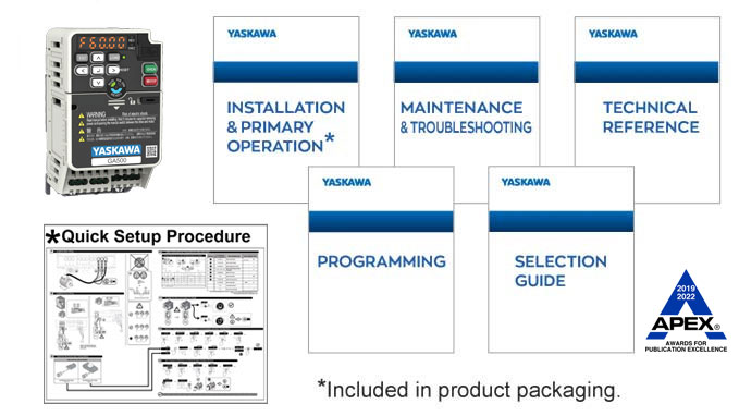
GA500 Manuals GA500 Manuals
| Title/Number | File(s) | Rev Date | |
|---|---|---|---|
|
Product Transition Guide V1000 to GA500 PL.GA500.01 Rev Date:03/11/2021 |
|
03/11/2021 | |
|
GA500 Versatile Compact AC Drive Technical Reference SIEPC71061752 Rev Date:06/02/2021 |
|
06/02/2021 | |
|
GA500 Selection Guide SL.GA500.01 Rev Date:07/23/2021 |
|
07/23/2021 | |
|
GA500 Finless-Type Installation & Primary Operation TOEPC7106170Y Rev Date:11/01/2021 |
|
11/01/2021 | |
|
GA500 Versatile Compact AC Drive Installation & Primary Operation TOEPC71061752 Rev Date:07/13/2021 |
|
07/13/2021 | |
|
GA500 Quick Setup Procedure TOEPC71061769 Rev Date:09/19/2019 |
|
09/19/2019 | |
|
GA500 Maintenance & Troubleshooting Manual TOEPYAIGA5001 Rev Date:11/18/2019 |
|
11/18/2019 | |
|
GA500 Programming Manual TOEPYAIGA5002 Rev Date:11/18/2019 |
|
11/18/2019 | |
 5.0MB
5.0MB Questions or comments?
Phone
If you have an urgent request, please call 1-800-YASKAWA (927-5292) or 1-847-887-7457.
Electronically
To contact us electronically, send email to: technical_documentation@yaskawa.com
Mail
Yaskawa America, Inc. — Drives & Motion Division
2121 Norman Drive South
Waukegan, IL 60085
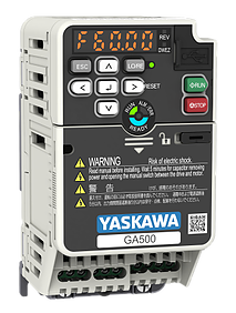
Описание модельного ряда
- Компактный инверторный привод
- Векторное регулирование без датчика обратной связи
- Выходная частота до 590 Гц
- Перегрузочная способность 150% — 1 минута
- Высокий пусковой крутящий момент
- Встроенный RS-485
- Встроенный программируемый контроллер
- Встроенный ЭМС фильтр
- Регулирование IM, iPM, sPM, SR двигателей
- Покрытие печатных плат
- Встроенный тормозной ключ
- Встроенные SIL3 Cat.3 Pl e for STO
- USB-mini порт для программирования
Схема маркировки
Модельный ряд
Интерфейсные карты
SI-ES3
Коммуникационная плата EtherCAT
SI-EP3
Коммуникационная плата ProfiNet
SI-P3
Коммуникационная плата ProfibusDP
SI-EN3
Коммуникационная плата EtherNet IP
SI-EN3D
Коммуникационная плата Dual Port EtherNet IP
SI-S3
Коммуникационная плата CANopen
SI-N3
Коммуникационная плата DeviceNET
SI-ET3
Коммуникационная плата Mechatrolink III
SI-T3
Коммуникационная плата Mechatrolink II
SI-C3
Коммуникационная плата CCLink
SI-EL3
Коммуникационная плата Powerlink
SI-EM3
Коммуникационная плата Modbus TCP
SI-EM3D
Коммуникационная плата Dual Port Modbus TCP
Аксессуары
JVOP-KPLEA04AAA
LED панель управления для инверторов GA700, GA500 (сегментный дисплей)
JVOP-KPLCC04ABA
LCD панель управления для инверторов GA700, GA500 с Bluetooth
JVOP-KPLCA04AEA
LCD панель управления для инверторов GA700, GA500 (стандартная для GA700, без Bluetooth)
900-192-933-001
Комплект для крепления на дверь шкафа панели оператора JVOP-KPLxxxxxxx, винтовой монтаж
900-192-933-002
Комплект для крепления на дверь шкафа панели оператора JVOP-KPLxxxxxxx, монтаж на шпильках
WV001-YEG
Удлинительный кабель для панели управления 1м
WV003-YEG
Удлинительный кабель для панели управления 3м
JOHB-GA50
Монтажный комплект для GA500, необходим для крепления и интерфейсных карт.
ZPBA-GA500
Монтажный комплект для крепления встроенной панели оператора GA500 на дверь шкафа
(пожалуйста установите JVOP-KPBCH04AAA в GA500 при внешнем креплении встроенной панели)
JVOP-KPBCH04AAA
Заглушка на место встроенной панели GA500 при ее внешнем креплении
Тормозные резисторы
Входные и выходные фильтры и дроссели
Технические описания
Документация
Каталоги
Технические руководства
Интерфейсные карты
Технические руководства к интерфейсным картам
Руководства по установке интерфейсных карт
Аксессуары
Руководства по установке панелей оператора
Руководства по установке монтажного комплекта
Преобразователи частоты YASKAWA GA500 c прошивкой каскадного управления 2 насосами (G5PD1912) могут управлять системой из двух насосов с одним преобразователем частоты (ПЧ), в случае если нецелесообразно использовать два ПЧ. В этом случае если ведущий насос достиг максимального уровня выходной частоты и нуждается в дополнительном напоре, тогда он дает сигнал на включение дополнительного насоса. Дополнительно ведется учет времени работы обоих насосов.
Последовательность работы
Автоматический режим работы основного насоса запускается, по включению (замыканию контакта) дискретного входа 1 (S1), при снятии сигнала работа режима будет приостановлена. Преобразователь частоты может быть настроен на фиксированную скорость или может работать в режиме ПИД-регулирования.
Если давление падает ниже значения «Низкий уровень давления» (Q1-01) на время большее чем задано в «Time 1» (Q3-01), включается сигнал (MC MA) запуска дополнительного насоса. Если давление превышает значение «Высокий уровень давления» (Q1-02) на время большее чем задано в параметре «Time 3» (Q3-03), выключается сигнал (MC MA) запуска дополнительного насоса.
Времена наработки насосов доступны в параметрах U4-01 для основного насоса и U8-23 для дополнительного. Учет идет в часах, максимальное значение 99999 часов. Данные доступны для просмотра как с пульта ПЧ, так и через цифровые протоколы связи: встроенный Modbus RTU или опциональные платы Modbus TCP, Profinet, Ethernet/IP, Powerlink и т.д.
Дополнительные функции и характеристики
Встроенный пульт управления ПЧ съемный и может быть установлен на дверцу шкафа для оперативного контроля и управления. Для удаленного подключения пульта используется стандартный кабель с разъемами RJ45. Функционал может быть расширен с использованием графических пультов от ПЧ GA700 с возможностью отображения графиков, с часами реального времени, возможностью ведения логов и подключения по Bluetooth.
Для настройки ПЧ серий GA не обязательно подавать силовое питание: достаточно просто подключится по USB c с компьютера или смартфона используя ПО DriveWizard или DriveWizardMobile соответственно.
Компактные размеры и не большой вес GA500 позволяют использовать его в простых применениях для замены ПЧ других производителей, например, VFD-СP, 100 FLOW, ATV61 и другие. Для схем с каскадным управлением 3 и более насосами и по сменным режимом работы используйте преобразователи частоты GA700.
GA500 обладают высокой надежностью элементной базы и рассчитаны на 10 лет работы 24 часа в сутки при температуре 40 С и нагрузке 80%. Предусмотрена возможность контроля выработки ресурса элементов ПЧ в зависимости от времени, температуры и нагрузки. Эти данные доступны через параметры ПЧ.
Рабочая температура ПЧ от -10 до +50 С, возможна работа до +60 С при снижении мощности нагрузки.