
-
Contents
-
Table of Contents
-
Bookmarks
Quick Links
Quadro comando
Quadro comando
per motoriduttori a 230 V
per motoriduttori a 230 V
ZM3E — ZM3EC — ZM3EP
ZM3E — ZM3EC — ZM3EP
MANUALE DI INSTALLAZIONE
MANUALE DI INSTALLAZIONE
FA01080M04
FA01080-IT
IT Italiano
EN English
FR Français
IT Italiano
RU Pусский
Related Manuals for CAME ZM3E
Summary of Contents for CAME ZM3E
-
Page 1
Quadro comando FA01080M04 FA01080-IT per motoriduttori a 230 V per motoriduttori a 230 V IT Italiano EN English ZM3E — ZM3EC — ZM3EP ZM3E — ZM3EC — ZM3EP FR Français IT Italiano RU Pусский MANUALE DI INSTALLAZIONE MANUALE DI INSTALLAZIONE… -
Page 2
• Il prodotto deve essere destinato solo all’uso per il quale è stato espressamente studiato. Ogni altro uso è da considerarsi pericoloso. CAME S.p.A. non è responsabile per eventuali danni causati da usi impropri, erronei ed irragionevoli • Prima di installare l’automazione verificare che la parte guidata sia… -
Page 3
sicurezza dall’area di manovra della parte guidata e dove non possono essere rag- giunti attraverso la parte guidata stessa • A meno che non sia previsto l’azionamento a chiave (Es: Selettore a tastiera, selettore a chiave, selettore transponder, ecc…) i dispositivi di comando ad azione mantenuta devono essere installati ad un’altezza di almeno 1,5 m e in un luogo non accessibile al pubblico •… -
Page 4
Le misure, se non diversamente indicato, sono in millimetri. DESCRIZIONE ZM3E — ZM3EP Quadro comando multifunzioni per cancelli a due ante a battenti, con display grafico di programmazione e segnalazione e autodiagnosi dei dispositivi di sicurezza. ZM3EC Quadro comando multifunzioni per porte a due ante a battenti, completo di blocco di sicurezza e pulsanti, con display grafico di programmazione e segnalazione e autodiagnosi dei dispositivi di sicurezza. -
Page 5
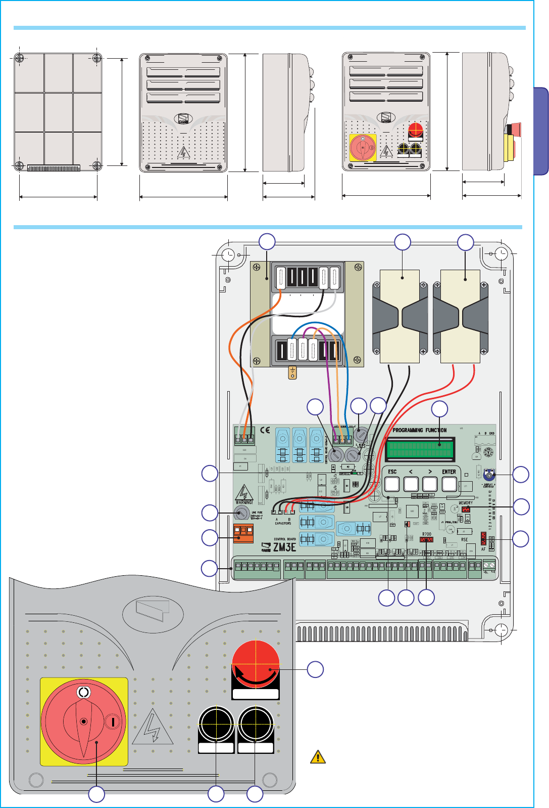
Descrizione delle parti Trasformatore 14. Connettore per scheda AF Condensatori* 15. Morsettiera per selettore a tastiera Fusibile scheda 16. Morsettiera per antenna Fusibile accessori 17. Morsettiera per uscita secondo canale Morsettiera per modulo RGP1 18. Morsettiera per finecorsa Fusibile elettroserratura 19. -
Page 6: Installazione
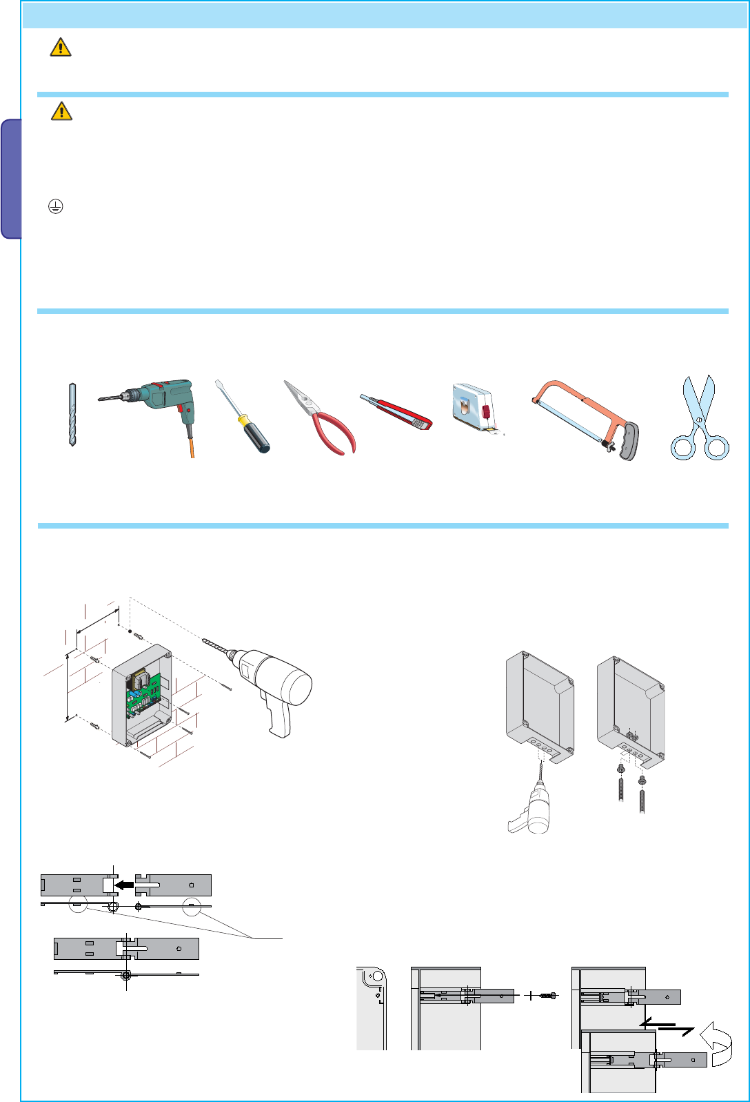
Solo per ZM3EC 30. Pulsante APERTURA 31. Blocco di sicurezza 28. Pulsante STOP 29. Pulsante CHIUSURA CAME Dimensioni INSTALLAZIONE Attrezzi e materiali Assicurarsi di avere tutti gli strumenti e il materiale necessario per effettuare l’installazione nella massima sicurezza e secondo…
-
Page 7
Tipo e sezione minima cavi lunghezza cavo Collegamento < 20 m 20 < 30 m Alimentazione quadro 3G x 1,5 mm 3G x 2,5 mm Alimentazione motore vedi manuali relative automazioni Dispositivi di segnalazione 2 x 0,5 mm2 Dispositivi di comando 2 x 0,5 mm2 Dispositivi di sicurezza (fotocellule) 2 x 0,5 mm2… -
Page 8: Collegamenti Elettrici
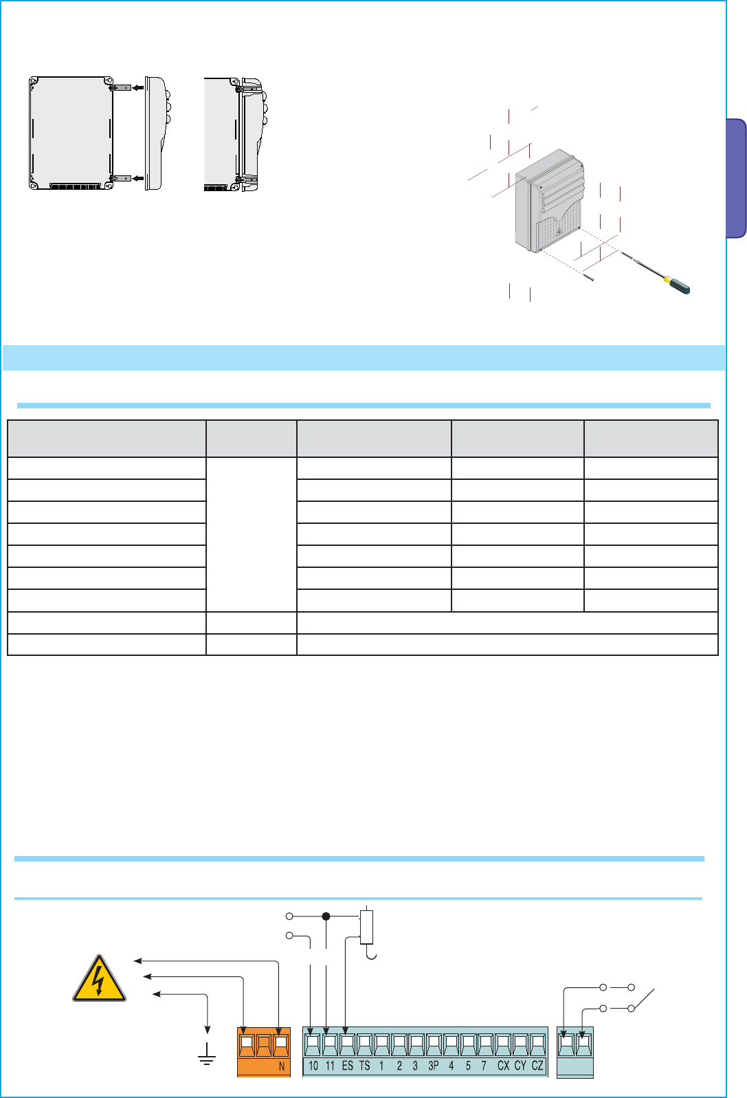
COLLEGAMENTI ELETTRICI Alimentazione Morsetti per l’alimentazione degli accessori a 24 V AC / DC — Potenza max: 20 W Collegamento elettroserratura (12V-15W max) 230 V AC 50/60 Hz Collegamento dei motoriduttori senza finecorsa FA1 FC1 FA2 FC2 M1 — Motoriduttore M2 — Motoriduttore ritardato in apertura.
-
Page 9
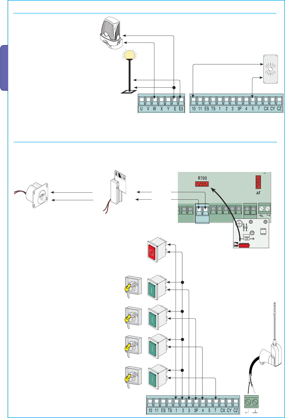
Collegamento dei motoriduttori con ENCODER M1 — Motoriduttore M2 — Motoriduttore ritardato in apertura. ritardato in chiusura. FA1 FC1 FA2 FC2 1 = Bianco / 2 = Marrone / 3 = Verde Dispositivi di segnalazione e illuminazione Lampada ciclo o cortesia. Lampadina spia cancello Lampada esterna liberamente posizionabile, per aperto. -
Page 10
Dispositivi di comando Pulsante di stop (contatto N.C.). — Per comandare l’arresto del cancello con l’esclusione del ciclo di chiusura automatica. Per riprendere il movimento bisogna premere un pulsante di comando o il tasto del trasmettitore. & Se non utilizzato, disattivare il contatto nel menu [FUNZIONI] → [Stop Totale]. -
Page 11
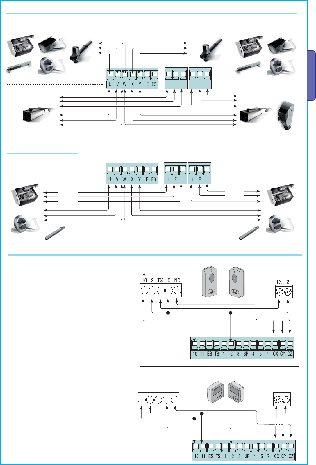
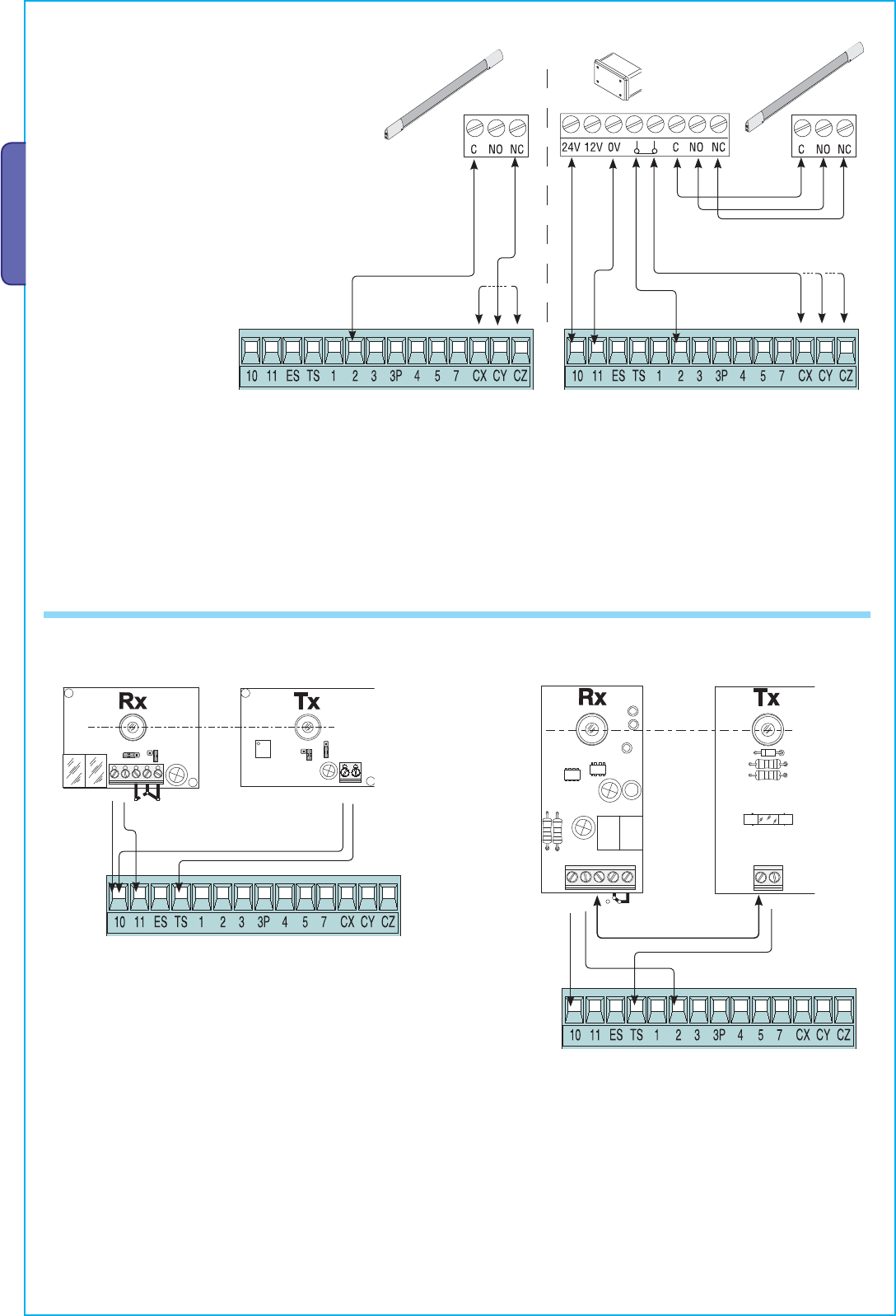
Dispositivi di sicurezza Delta Dir/DeltaS Collegamento fotocellule (contatto NC) — Vedi menu [FUNZIONI] → [ingresso CX], [ingresso CY] o [ingresso CZ] per associare a ogni ingresso una modalità di funzionamento. & Se non vengono utilizzati, i contatti CX, CY e CZ vanno disattivati in programmazione. Collegamento fotocellule per Funzione test di sicurezza — Vedi menu [FUNZIONI] →… -
Page 12
Collegamento CRP A B GND UTP CAT 5 Collegamento seriale RS485 all’impianto domotico via CRP (Came Remote Protocol). Inserire la scheda RSE in assenza di tensione. A B GND ATTIVAZIONE DEL COMANDO RADIO Antenna e scheda di radiofrequenza AF Collegare il cavo RG58 dell’antenna agli appositi morsetti. -
Page 13
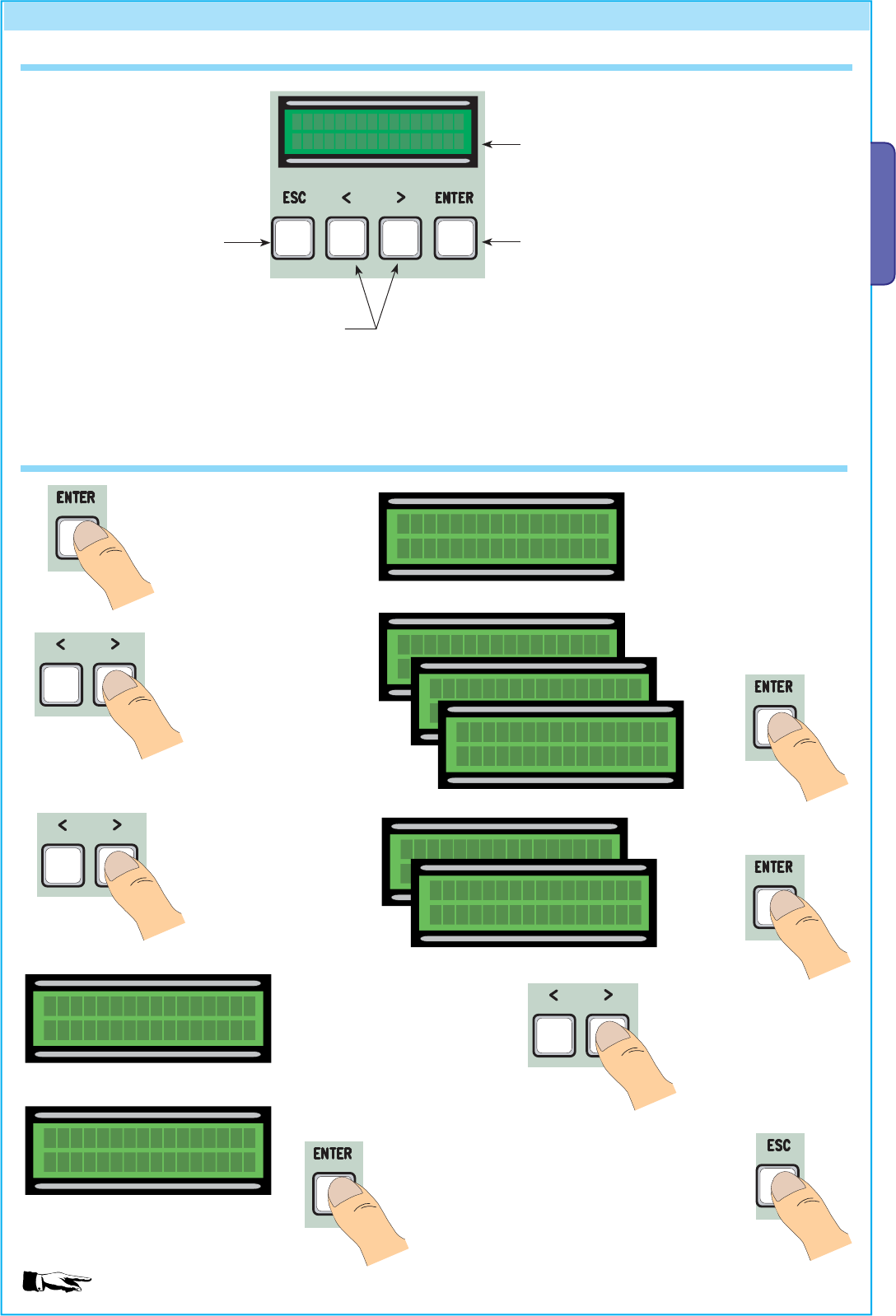
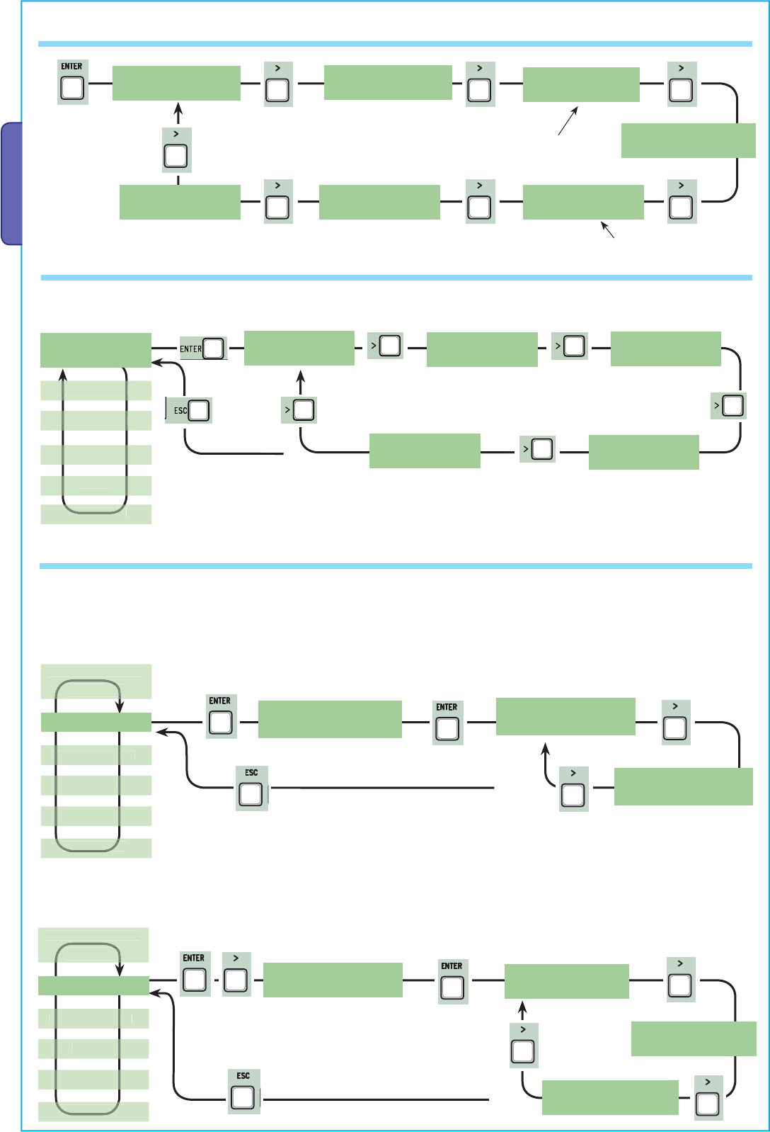
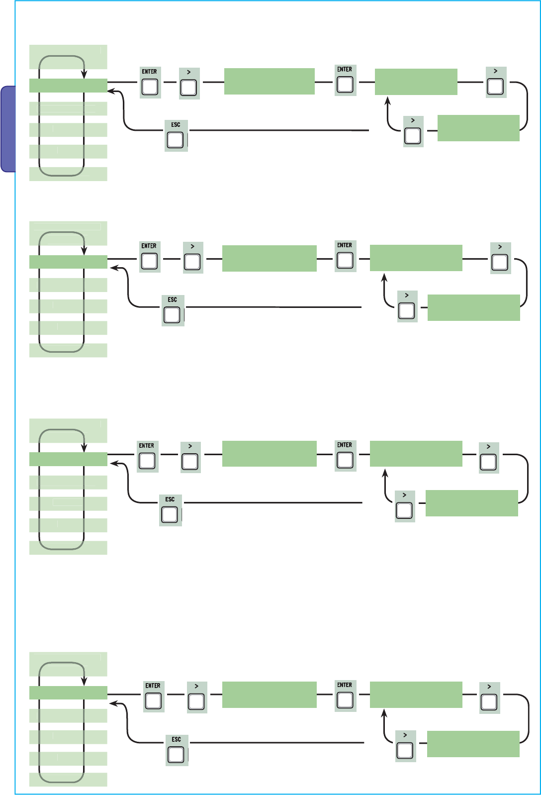
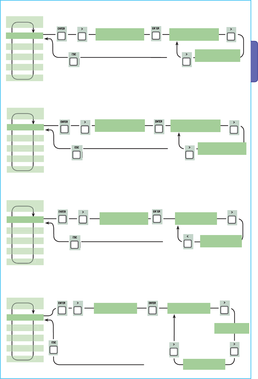
— incrementare o decrementare un valore. Per entrare nel menu, tenere Per scegliere una voce di menu, premuto per almeno un spostarsi con / e confermare con secondo. WWW.CAME.IT FUNZIONI < LINGUA > ENCODER Italiano < REGOLA TEMPI > …per uscire dal menu aspettare… -
Page 14
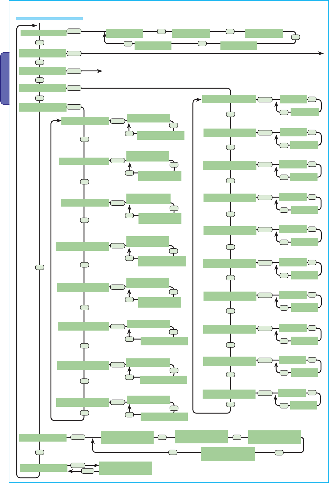
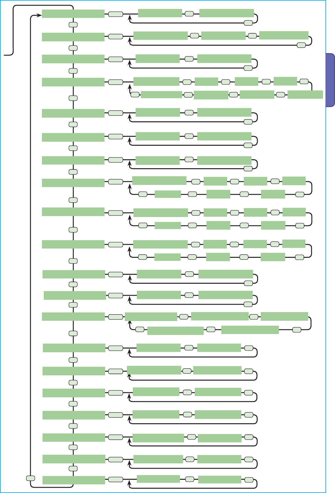
& IMPORTANTE! Iniziare la programmazione da [Tipo Motore], [Num. Motori], [Stop Totale] dal menu [FUNZIONI] e [Taratura Corsa] dal menu [ENCODER]. Menu 1° livello Menu 2° livello Opzioni Default [LINGUA] [Italiano] / [English] / [Français] / [Deutsch] / [Español] / [Italiano] [Portugues euro]/[Portugues bras] [FUNZIONI]… -
Page 15
Menu 1° livello Menu 2° livello Opzioni Default Scelta della modalità di funzionamento del dispositivo collegato. Per fotocellule: — C1 Riapertura durante la chiusura. In fase di chiusura delle ante, l’apertura del contatto provoca l’inversione del movimento fino alla completa apertura; — C2 richiusura durante l’apertura. -
Page 16
[1] …… [32] [Indirizzo CRP] In caso di impianto con più automazioni con sistema di connessione CRP (Came Remote Protocol), impostare un indirizzo da 1 a 32 per ogni quadro. [1200] / [2400] / [4800] / [9600] / [19200] / [38400] /… -
Page 17
Menu 1° livello Menu 2° livello Opzioni Default [1%] …… [60%] [M1 Rall.AP %] [10%] Regolazione del punto di inizio del rallentamento di M1 prima del finecorsa di apertura, calcolato in percentuale (da 1% a 60% della corsa completa). & Questa funzione compare solo se viene attivata la funzione [Rallent.Enc] nel menu [ENCODER]. -
Page 18
Menu 1° livello Menu 2° livello Opzioni Default Ritardo di apertura di M1 rispetto all’apertura di M2 dopo ogni comando di aper- tura. Il tempo di attesa può essere regolato da 0 s a 10 s. [0 s] …… [60 s] [Rit. -
Page 19
[Numero Corse] Visualizza il numero di manovre effettuate. [Msg. iniziale] WWW.CAME.IT Visualizza il messaggio iniziale. Per modificare il testo, premere ENTER; Utilizzare il tasto ENTER per spostare il cursore in avanti, ESC per spostare il cursore all’indie- tro e / per selezionare la lettera o cifra. Confermare il testo premendo il tasto ENTER per alcuni secondi. -
Page 20
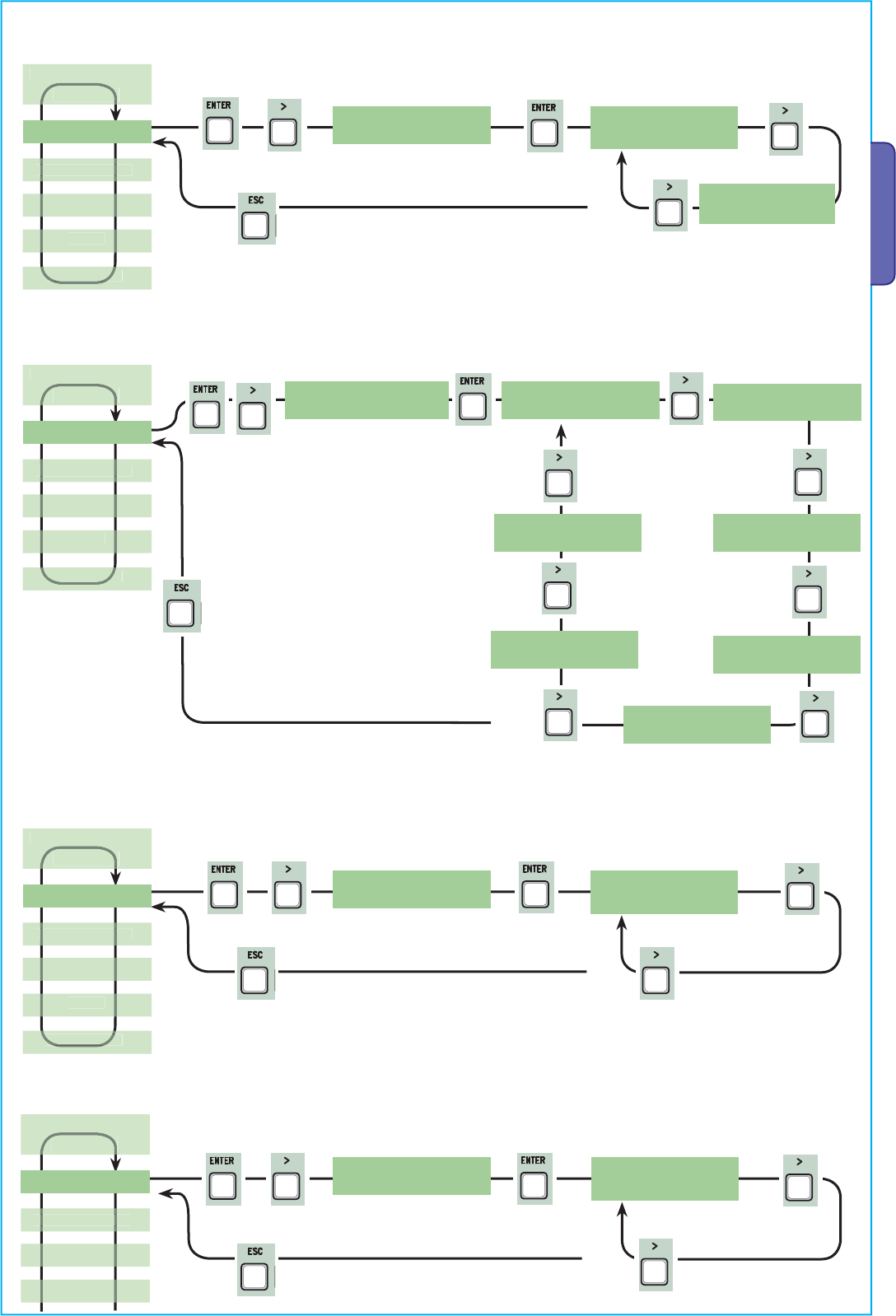
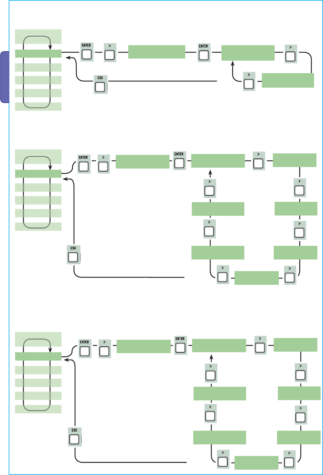
Inserimento nuovo utente 1. Dal menu [UTENTI], selezionare 3. Scegliere la funzione da associare [Nuovo Utente]. Premere ENTER per 2. Selezionare [Confermi?(si)] e all’utente. Premere ENTER per confermare. premere ENTER per confermare. confermare… Funz.Associata Nuovo Utente < Nuovo Utente > <… -
Page 21
Modifica codice 3..verrà richiesto un codice da 1. Dal menu [UTENTI], selezionare 2. Selezionare l’utente di cui si inserire (trasmettitore, tastiera, [Mod. Codice]. Premere ENTER per vuole modificare il codice e premere tessera a strisciamento o confermare. ENTER. transponder). -
Page 22
Taratura corsa ⚠ Prima di effettuare la taratura della corsa, controllare che l’area di manovra sia libera da qualsiasi ostacolo e verificare la presenza di una battuta d’arresto meccanico in apertura e una in chiusura. ⚠ Le battute d’arresto meccanico sono obbligatorie. Importante! Durante la taratura, tutti dispositivi di sicurezza saranno disabilitati escluso quello per lo STOP TOTALE. -
Page 23
MESSAGGI DI ERRORE Messaggio Significato [Encoder — ERRORE], [Errore!] Encoder rotto o collegamento errato. [test Sicurezze — ERRORE] Malfunzionamento dei dispositivi di sicurezza. [Fine corsa — ERRORE] Malfunzionamento sui contatti dei finecorsa [Tempo Lavoro — ERRORE] Tempo lavoro insufficiente [Sicurezze — STOP], [C1], [C3], Malfunzionamento dei dispositivi di sicurezza o [C4], [C7] o [C8] collegamento errato… -
Page 24: Operazioni Finali
NON DISPERDERE NELL’AMBIENTE! RIFERIMENTI NORMATIVI CAME SPA dichiara che il prodotto è conforme alle direttive di riferimento vigenti al momento della produzione dello stesso. I contenuti del manuale sono da ritenersi suscettibili di modifica in qualsiasi momento senza obbligo di preavviso.
-
Page 25
Control panel FA01080-EN for 230Vgearmotors EN English ZM3E — ZM3EC — ZM3EP INSTALLATION MANUAL… -
Page 26
Any other use is dangerous. CAME S.p.A. is not liable for any damage caused by improper, wrongful and unreasonable use. • Before installing the control panel, make sure that the gui-… -
Page 27
will cease to be effective. • All maintained-action switches that are connected to the control panel must be positioned so that the maneuvering area is completely visible from the switches, yet far enough away from any moving parts. • Make sure that the operator has been properly adjusted and that any associated safety and protection devices, as well as the gearmotor’s manual release, are working properly. -
Page 28
The measurements, unless otherwise stated, are in millimeters. DESCRIPTION ZM3E — ZM3EP Multifunction control-panel for two leaved swing-gates, with graphic programming and alert display, and self-diagnosing safety devices. ZM3EC Multifunction control panel for two-leaved swing doors, complete with safety lock and buttons, with graphic pro- gramming display and signaling, plus self-diagnosing safety devices. -
Page 29
Description of parts Transformer 15. Keypad selector terminal Condensers* 16. Antennaterminals Control-boardfuse 17. Second-channel output terminals Accessories fuse 18. Limit-switchterminals Terminal board for RGP1 module 19. Terminals for transponder devices Electric-lockfuse 20. Terminals forcontrol and safety devices Display 21. Encoderterminals Display-brightness adjustingtrimmer 22. -
Page 30: Installation
28. STOP button 29. CLOSE button 30. OPEN button 31. Safety lock CAME Dimensions INSTALLATION Tools and materials Make sure you have all the tools and materials you will need for installing in total safety and in compliance with applicable…
-
Page 31
Cable type and minimum section cable length Connection < 20 m 20 < 30 m Control panel power-supply 3G x 1.5 mm 3G x 2.5 mm Motor power supply see the corresponding operator-manuals Signaling devices 2 x 0.5 mm2 Command and control devices 2 x 0.5 mm2 Safety devices (photocells) 2 x 0.5 mm2… -
Page 32: Electrical Connections
ELECTRICAL CONNECTIONS Input voltage Terminal board for 24 V AC / DC accessories — Max. power: 20 W Connecting the electric lock (12V-15W max) 230 V AC 50/60 Hz Connecting the gearmotors that have no limit switch FA1 FC1 FA2 FC2 M1 — Gearmotor with M2 — Gearmotor with delayed opening.
-
Page 33
Connecting ENCODER-fitted gearmotors M1 — Gearmotor with M2 — Gearmotor with delayed opening. delayed closing. FA1 FC1 FA2 FC2 1 = White / 2 = Brown / 3 = Green Warning and lighting devices Cycle or courtesy light. Gate open warning-light- It Freelyplaceable, outdoor light, to illuminate the warns that the gate is open and driveway. -
Page 34
Command and control devices Stop button (N.C. contact). — For commanding the gate to stop while excluding the automatic-closing time cycle. To resume movement, press a button on the control or the transmitter button. & If unused, deactivate the contact in the [FUNCTIONS] menu → [Total Stop]. -
Page 35
Safety devices Delta Dir/DeltaS Photocells connections (N.C. contact) — See [FUNCTIONS] menu → [input CX], [input CY] or [input CZ] for associating an operating mode to each input. & If unused, contacts CX, CY and CZ should be disabled during programming. Connecting photocells for Safety-test function — See [FUNCTIONS] menu →… -
Page 36
CRP connection A B GND UTP CAT 5 RS485 serial connection to the home & building automation system via CRP (Came Remote Protocol). Fit the RSE card only when the mains power A B GND is cut off. ENABLING THE RADIO CONTROL… -
Page 37
— increasing or decreasing values. To select a menu item, move using To enter the menu, keep pressed the / arrows and confirm with for at least one second. WWW.CAME.IT FUNZIONI < LINGUA > ENCODER Italiano < REGOLA TEMPI >… -
Page 38
& IMPORTANT! Start programming from [Motor Type], [No. of Motors], [Total Stop] window from the [FUNCTIONS] menu and [Gate-Swing Calibration] window from the [ENCODER] menu. Menu 1st level Menu 2nd level Options Default [LANGUAGE] [Italiano] / [English] / [Français] / [Deutsch] / [Español] / [English] [Portugues euro]/[Portugues bras] [FUNCTIONS]… -
Page 39
Menu 1st level Menu 2nd level Options Default [CY input] [Disabled] / [C1] / [C2] / [C3] / [C4] / [C7] / [C8] [C3] See [CX Input] [CZ input] [Disabled] / [C1] / [C2] / [C3] / [C4] / [C7] / [C8] [Disabled] See [CX Input] [Cl. -
Page 40
[1] …… [32] [CRP Address] With systems fitted with several operators and the CRP (Came Remote Protocol) system connection, set an address between 1 and 32 for each control panel. [1200] / [2400] / [4800] / [9600] / [19200] / [38400] /… -
Page 41
Menu 1st level Menu 2nd level Options Default Setting the starting slow-down of M2 before the closing limit-switch point, calcu- lated as a percentage (from 1% to 60% of the full leaf-swing). & This function only appears if the [Enc. Slodwn.] function is enabled in the [ENCODER] menu. -
Page 42
[Number of Runs] View the number of completed maneuvers. [Open. Msg.] WWW.CAME.IT View opening message. To edit the text, press ENTER. Use ENTER to move the cursor forward, and ESC to move the cursor backwards and / to select the letter or figure. -
Page 43
Menu 1st level Menu 2nd level Options Default To restore the initial settings. Press ENTER to confirm the Reset. [MOT TEST] [<=M1 M2=>] For checking the proper rotation direction of the gearmotors. Keepthe < key pressed for some seconds and check that M1’s leaf has opened. If the rotation direction is wrong, invert the motor’s phases. -
Page 44
Entering a new user 1. From the [USERS] menu, select 2. Select [Confirm?(yes)] and press 3. Select the function to associate to [New User]. Press ENTER to confirm. ENTER to confirm. users. Press ENTER to confirm… Funz.Associata Nuovo Utente < Nuovo Utente > <… -
Page 45
Modify code 3..you will be asked a code 1. From the [USERS], select [Edit 2. Select the user whose code you to enter representing a transmitter, Code]. Press ENTER to confirm. want to edit and press ENTER. keypad, swipe card or transponder. -
Page 46
Gate-swing calibration ⚠ Before calibrating the gate-swing, check that the maneuvering area is free from any obstruction and that there are both opening and closing mechanical gate-stops. ⚠ The mechanical gate-stops are obligatory. Important! During the calibration, all safety devices will be disabled except for the PARTIAL STOP one. 1. -
Page 47: Error Message
ERROR MESSAGE System Meaning [Encoder — ERROR], [Error!] Broken encoder or wrong connection. [Safety test — ERROR] Safety devices malfunctioning. [Limit-switch — ERROR] Malfunctioning limit-switch contacts [Operating Time — ERROR] Insufficient operating time [Safety — STOP], [C1], [C3], [C4], Malfunctioning safety devices or wrong connection [C7] or [C8] GRAPHIC LAYOUT OF THE ENCODER’S FUNCTIONS &…
-
Page 48: Dismantling And Disposal
DISPOSE OFRESPONSIBLY! REFERENCE REGULATIONS CAME SpA declares that this product complies with the current directives at the time it is manufactured. The contents of this manual may change, at any time, and without notice. CAME S.p.A.
-
Page 49: Manuel D’installation
Armoire de commande FA01080-FR pour motoréducteurs 230 V FR Français ZM3E — ZM3EC — ZM3EP MANUEL D’INSTALLATION…
-
Page 50
• Le produit ne devra être destiné qu’à l’utilisation pour laquelle il a été expressément conçu. Toute autre utilisation est à considérer comme dangereuse. CAME S.p.A. décline toute responsabilité en cas de dommages provoqués par des utilisations impropres, incorrectes ou déraisonnables •… -
Page 51
Tous les dispositifs de commande et de contrôle doivent être bien en vue et installés à une distance de sécurité adéquate par rapport à la zone d’actionnement de la partie guidée et en des points inaccessibles à travers la partie en question • À défaut d’action- nement par badge (ex. -
Page 52
Les dimensions sont exprimées en millimètres, sauf indication contraire. DESCRIPTION ZM3E — ZM3EP Armoire de commande multifonctions pour portails battants à deux vantaux avec afficheur de programma- tion et de signalisation, et autodiagnostic des dispositifs de sécurité. ZM3EC Armoire de commande multifonctions pour portes battantes à deux vantaux avec dispositif de blocage de sécurité… -
Page 53
Description des parties Transformateur 14. Connecteur pour carte AF Condensateurs* 15. Bornier pour clavier à code Fusible carte 16. Bornier pour antenne Fusible accessoires 17. Bornier pour sortie deuxième canal Bornier pour module RGP1 18. Bornier pour fin de course Fusible serrure de verrouillage électrique 19. -
Page 54
Pour ZM3EC uniquement 28. Bouton ARRÊT 29. Bouton FERMETURE 30. Bouton OUVERTURE 31. Blocage de sécurité CAME Dimensions INSTALLATION Outils et matériel S’assurer de disposer de tous les instruments et de tout le matériel nécessaire pour effectuer l’installation en toute sécurité… -
Page 55
Type et section minimale des câbles longueur câble Connexion < 20 m 20 < 30 m Alimentation armoire 3G x 1,5 mm 3G x 2,5 mm Alimentation moteur voir les manuels des automatismes Dispositifs de signalisation 2 x 0,5 mm2 Dispositifs de commande 2 x 0,5 mm2 Dispositifs de sécurité… -
Page 56: Branchements Électriques
BRANCHEMENTS ÉLECTRIQUES Alimentation Bornes d’alimentation des accessoires en 24 VAC / DC — Puissance max. : 20 W Connexion serrure de verrouillage électrique (12 V-15 W max.) 230 VAC 50/60 Hz Connexion des motoréducteurs sans fin de course FA1 FC1 FA2 FC2 M1 — Motoréducteur M2 — Motoréducteur retardé…
-
Page 57
Connexion des motoréducteurs avec ENCODEUR M1 — Motoréducteur M2 — Motoréducteur retardé en phase retardé en phase de d’ouverture. fermeture. FA1 FC1 FA2 FC2 1 = Blanc / 2 = Marron / 3 = Vert Dispositifs de signalisation et d’éclairage Lampe cycle ou d’accueil. -
Page 58
Dispositifs de commande Bouton d’arrêt (contact N.F.). — Pour commander l’arrêt du portail avec désactivation du cycle de fermeture automatique. Pour la reprise du mouvement, appuyer sur un bouton de commande ou sur la touche de l’émetteur. & S’il n’est pas utilisé, désactiver le contact dans le menu [FONCTIONS] →… -
Page 59
Dispositifs de sécurité Delta Dir/DeltaS Connexion photocellules (contact NF) — Voir menu [FONCTIONS] → [entrée CX], [entrée CY] ou [entrée CZ] pour associer un mode de fonctionnement à chaque entrée. & En cas de non utilisation des contacts CX, CY et CZ, les désactiver durant la phase de programmation. Connexion photocellules pour Fonction test de sécurité… -
Page 60
Connexion CRP A B GND UTP CAT 5 Connexion série RS485 à l’installation domotique via CRP (Came Remote Protocol). Installer la carte RSE avec dispositif hors tension. A B GND ACTIVATION DE LA COMMANDE RADIO Antenne et carte de radiofréquence AF Connecter le câble RG58 de l’antenne aux bornes… -
Page 61
Pour choisir une option de menu, se enfoncée pendant au moins une déplacer à l’aide des flèches / et seconde. confirmer par WWW.CAME.IT FUNZIONI < LINGUA > ENCODER Italiano < REGOLA TEMPI > …pour sortir du menu, attendre 30 secondes, ou appuyer sur , jusqu’à… -
Page 62
& IMPORTANT ! Commencer la programmation par [Type Moteur], [Nbre Moteurs], [Arrêt Total] depuis le menu [FONCTIONS] et [Auto-apprentissage Course] depuis le menu [ENCODEUR]. Menu 1er niveau Menu 2e niveau Options Par défaut [LANGUE] [Italiano] / [English] / [Français] / [Deutsch] / [Español] / [Français] [Portugues euro]/[Portugues bras] [FONCTIONS]… -
Page 63
Menu 1er niveau Menu 2e niveau Options Par défaut Sélection du mode de fonctionnement du dispositif connecté. Pour photocellules : — C1 Réouverture durant la fermeture. Durant la phase de fermeture des van- taux, l’ouverture du contact provoque l’inversion du mouvement jusqu’à l’ouverture totale ;… -
Page 64
[1] …… [32] [Adresse CRP] En cas d’installation prévoyant plusieurs automatismes avec système de connexion CRP (Came Remote Protocol), configurer une adresse de 1 à 32 pour chaque armoire. [1200] / [2400] / [4800] / [9600] / [19200] / [38400] /… -
Page 65
Menu 1er niveau Menu 2e niveau Options Par défaut Sensibilité de la détection des obstacles durant le ralentissement (aussi bien à l’ouverture qu’à la fermeture). & Il faut activer la fonction [Ralent. Enc.] dans le menu [ENCODEUR]. [Ral. Enc.] [ON] / [OFF] [ON] Activation des points de ralentissement en ouverture et en fermeture. -
Page 66
Menu 1er niveau Menu 2e niveau Options Par défaut Délai d’attente du deuxième vantail (M2) en position d’ouverture. Après écoule- ment de ce délai, une manœuvre de fermeture est automatiquement effectuée. Le temps d’attente peut être réglé entre 0 et 300 secondes. [Temps Fonction- [10 s] ……… -
Page 67
[Nbre Courses] Permet de visualiser le nombre de manœuvres effectuées. [Msg. initial] WWW.CAME.IT Permet de visualiser le message initial. Pour modifier le texte, appuyer sur ENTER ; Utiliser la touche ENTER pour déplacer le curseur en avant, ESC pour le déplacer en arrière et… -
Page 68
Introduction nouvel utilisateur 1. Dans le menu [UTILISATEURS], 3. Choisir la fonction à associer à sélectionner [Nouvel Utilisateur]. 2. Sélectionner [Confirmer ?(oui)] et l’utilisateur. Appuyer sur ENTER pour Appuyer sur ENTER pour confirmer. appuyer sur ENTER pour confirmer. confirmer… Funz.Associata Nuovo Utente <… -
Page 69
Modification code 1. Dans le menu [UTILISATEURS], 2. Sélectionner l’utilisateur dont on 3..le système demandera de taper sélectionner [Mod. Code]. Appuyer souhaite modifier le code et appuyer un code (émetteur, clavier, carte à sur ENTER pour confirmer. sur ENTER. bande magnétique ou transpondeur). -
Page 70
Auto-apprentissage de la course ⚠ Avant de régler la course, s’assurer que la zone de manœuvre ne présente aucun obstacle et s’assurer de la présence d’une butée d’arrêt mécanique aussi bien à l’ouverture qu’à la fermeture. ⚠ Les butées d’arrêt mécanique sont obligatoires. Important ! Durant le réglage, tous les dispositifs de sécurité… -
Page 71: Messages D’erreur
MESSAGES D’ERREUR Message Signification [Encodeur — ERREUR], [Erreur !] Encodeur cassé ou connexion incorrecte. [test Sécurité — ERREUR] Mauvais fonctionnement des dispositifs de sécurité. Mauvais fonctionnement sur les contacts des [Fin de course — ERREUR] butées de fin de course [Durée Cycle — ERREUR] Temps de fonctionnement insuffisant [Sécurité…
-
Page 72
NE PAS JETER DANS LA NATURE ! RÉFÉRENCES NORMATIVES CAME SPA déclare que ce produit est conforme aux directives de référence en vigueur au moment de sa production Le contenu de ce manuel est susceptible de subir des modifications à tout moment et sans aucun préavis. -
Page 73: Руководство По Установке
Блок управления FA01080-RU электроприводамиприводами ~230 В RU Русский ZM3E — ZM3EC — ZM3EP РУКОВОДСТВО ПО УСТАНОВКЕ…
-
Page 74
выполняться исключительно квалифицированным и компетентным персоналом • Это изделие должно использоваться исключительно по назначению. Любое другое применение считается опасным. CAME S.p.A. не несет никакой ответ- ственности за ущерб, нанесенный неправильным, ошибочным или небрежным использованием изделия •Перед установкой автоматики, убедитесь в том, что… -
Page 75
с присутствием людей в зоне работы автоматики. Необходимо предупредить обо всех остаточных рисках с помощью специальных символов, расположив их на видном месте, и доходчиво объяснить их конечному пользователю • По завер- шении установки системы прикрепите к ограждению паспортную табличку • Все устройства… -
Page 76: Условные Обозначения
Этот символ обозначает раздел, предназначенный для ознакомления конечного пользователя. Размеры, если не указано иное, в миллиметрах. ОПИСАНИЕ ZM3E — ZM3EP Многофункциональный блок управления двустворчатыми распашными воротами с дисплеем и функцией самодиагностики устройств безопасности. ZM3EC Многофункциональный блок управления двустворчатыми воротами c сетевым выключателем на крыш- ке, кнопками, дисплеем…
-
Page 77
Основные компоненты Трансформатор 15. Контакты подключения кодонаборной Конденсаторы* клавиатуры Предохранители платы 16. Контакты подключения антенны Предохранитель аксессуаров 17. Контакты выхода второго канала Контакты подключения модуля RGP1 18. Контакты подключения концевых выключателей Предохранитель электрозамка 19. Контакты подключения проксимити-устройств Дисплей 20. Контакты подключения устройств управления и Регулировка… -
Page 78
Только для ZM3EC 28. Кнопка «СТОП» 29. Кнопка «ЗАКРЫТЬ» 30. Кнопка «ОТКРЫТЬ» 31. Блокировка CAME Габаритные размеры УСТАНОВКА Инструменты и материалы Перед началом монтажных работ убедитесь в наличии всех необходимых инструментов и материалов, которые позволят произвести установку системы в полном соответствии с действующими нормами безопасности. На… -
Page 79
Тип и минимальное сечение кабелей Длина кабеля Подключение < 20 м 20 < 30 м Электропитание блока управления 3G x 1,5 мм 3G x 2,5 мм Смотрите техническую документацию Электропитание мотора на соответствующие автоматические системы. Устройства сигнализации 2 x 0,5 мм Устройства… -
Page 80: Электрические Подключения
ЭЛЕКТРИЧЕСКИЕ ПОДКЛЮЧЕНИЯ Электропитание Контакты электропитания аксессуаров ~/=24 В — Макс. мощность: 20 Вт Подключение электрозамка (12 В, 15 Вт макс.) ~230 В 50/60 Гц Подключение приводов без концевых выключателей FA1 FC1 FA2 FC2 M1 — Привод с замед- M2 — Привод с ленным…
-
Page 81
Подключение приводов с ЭНКОДЕРОМ M1 — Привод с замед- M2 — Привод с ленным открыванием. замедленным закрыванием. FA1 FC1 FA2 FC2 1 = Белый / 2 = Коричневый / 3 = Зеленый Устройства сигнализации и освещения Лампа цикла или лампа дополнительного Лампа-индикатор… -
Page 82
Устройства управления Кнопка «Стоп» (нормально-замкнутые контакты). — Останавливает движение ворот, исключая цикл автоматического закрывания. Чтобы ворота возобновили движение, необходимо нажать соответствующую кнопку управления или пульта ДУ. & Если контакт не используются, отключите его в меню [FUNCTIONS] → [Total Stop]. Ключ-выключатель и/или кнопка открывания (нормально- разомкнутые… -
Page 83
Устройства безопасности Delta Dir/DeltaS Подключение фотоэлементов (нормально-замкнутые контакты) — См. меню [FUNCTIONS] → [CX Input], [CY Input] или [CZ Input] для присвоения каждому входу режима работы. & Если контакты CX, CY и CZ не используются, отключите их во время программирования. Подключение… -
Page 84
Подключение посредством CRP A B GND UTP CAT 5 Последовательное подключение RS485 к «умному дому» посредством CRP (Came Remote Protocol). Отключите электропитание и вставьте A B GND плату RSE. АКТИВАЦИЯ РАДИОУПРАВЛЕНИЯ Антенна и плата радиоприемника АF Подключите антенный кабель RG58 к… -
Page 85
кнопку и удерживайте Для перемещения между ее в этом положении не менее пунктами меню используйте / , одной секунды. а для выбора — WWW.CAME.IT FUNZIONI < LINGUA > ENCODER Italiano < REGOLA TEMPI > …чтобы выйти из меню, подождите 30 секунд… -
Page 86
& ВАЖНО! Начните процедуру программирования с функций [Motor Type], [No. of motors], [Total Stop] в меню [FUNCTIONS] и [Travel Calibr] в меню [ENCODER]. Меню 1-го Меню 2-го Настройки По умолчанию уровня уровня [LANGUAGE] [Italiano] / [English] / [Français] / [Deutsch] / [Español] / [English] [Portugues euro]/[Portugues bras] [FUNCTIONS]… -
Page 87
Меню 1-го Меню 2-го Настройки По умолчанию уровня уровня Выбор режима работы подключенного устройства. Для фотоэлементов: — C1 Открывание в режиме закрывания. Размыкание контактов во время закрывания ворот приводит к изменению направления движения на противо- положное, вплоть до полного открывания. — C2 Закрывание… -
Page 88
[1] …… [32] [CRP address] При использовании нескольких автоматических устройств с системой подключения CRP (Came Remote Protocol) установите номер от 1 до 32 для каждого блока управления. [1200] / [2400] / [4800] / [9600] / [19200] / [38400] / [CRP Baudrate]… -
Page 89
Меню 1-го Меню 2-го Настройки По умолчанию уровня уровня Чувствительность токовой системы обнаружения препятствий во время движения (как при открывании, так и при закрывании ворот) & Необходимо активировать функцию [Sensitivity] в меню [ENCODER]. [-◦ ◦ ◦ ◦ ◦ ◦ ◦ ◦+] [-・… -
Page 90
Меню 1-го Меню 2-го Настройки По умолчанию уровня уровня Отсчет времени автоматического закрывания начинается с момента до- стижения воротами концевого выключателя открывания. Время регули- руется в диапазоне от 0 до 300 с. Функция автоматического закрывания блокируется, если в результате обнаружения препятствия срабатывают устройства… -
Page 91
Показывает версию программного обеспечения. [No. Of Travels] Указывает число циклов работы приводов. [Start message] WWW.CAME.IT Показывает приветственное сообщение. Для изменения текста нажмите клавишу «ВВОД» (ENTER). Используйте клавишу «ВВОД» для перемещения курсора вперед, «ВЫХОД» (ESC) для перемещения курсора назад и для выбора цифр или букв. Для подтверждения удерживайте ENTER в… -
Page 92
Добавление нового пользователя 2. Выберите [Confirm?(yes)] и 3. Выберите присваиваемую поль- 1. В меню [USERS] выберите [Add нажмите «ВВОД» (ENTER) для под- зователю функцию. Подтвердите, User]. Подтвердите, нажав ENTER. тверждения. нажав кнопку ENTER… Funz.Associata Nuovo Utente < Nuovo Utente > <… -
Page 93
Изменение кода 1. В меню [USERS] выберите 2. Выберите имя пользователя, 3..потребуется ввести код (пульт [Change Code]. Подтвердите, код которого вы хотите изменить, ДУ, кодонаборная клавиатура, нажав ENTER. и нажмите ENTER. магнитная или проксимити-карта). Attesa Codice < Mod. Codice > Mod. -
Page 94
Калибровка движения ⚠ Перед тем как отрегулировать движение створок, убедитесь в отсутствии каких-либо препятствий и наличии механических упоров открывания и закрывания. ⚠ Использование механических упоров является обязательным. Важно! Все устройства безопасности, за исключением кнопки «СТОП», будут отключены до полного завершения процедуры. -
Page 95: Сообщения Об Ошибках
СООБЩЕНИЯ ОБ ОШИБКАХ Сообщение Значение Энкодер неисправен или отсутствуеи [Encoder — ERROR], [Error!] подключение. [Safety Test — ERROR] Неисправность устройств безопасности. Неисправность контактов концевых [End Stop — ERROR] выключателей [Cycle Time — ERROR] Недостаточное время работы Неисправность устройств безопасности или [Ssafety — STOP], [C1], [C3], [C4], [C7] или…
-
Page 96: Заключительные Работы
могут содержать загрязняющие вещества. Они должны передаваться компаниям, имеющим лицензию на их переработку. НЕ ЗАГРЯЗНЯЙТЕ ОКРУЖАЮЩУЮ СРЕДУ! НОРМЫ И СТАНДАРТЫ Компания CAME SPA заявляет, что данное изделие соответствует требованиям директив, действовавших на момент его производства. Содержание данного руководства может быть изменено в любое время без предварительного уведомления.
- Home
- Инструкции
- Автоматика для ворот
- CAME
- ZM3E
![]() Электронный блок управления CAME ZM3E инструкция по монтажу на русском языке в формате pdf, размер файла 2.2 Mb. Используйте кнопки «Скачать инструкцию» или «Открыть в новом окне» (документ откроется в новом окне или вкладке браузера). Функция просмотра доступна при наличии плагина Adobe Acrobat в вашем браузере.
Электронный блок управления CAME ZM3E инструкция по монтажу на русском языке в формате pdf, размер файла 2.2 Mb. Используйте кнопки «Скачать инструкцию» или «Открыть в новом окне» (документ откроется в новом окне или вкладке браузера). Функция просмотра доступна при наличии плагина Adobe Acrobat в вашем браузере.
CAME ZM3E инструкция
Язык: Русский
Размер : 2.2 Mb
Формат файла: pdf
Добавлен: 20.06.2013
Руководство по установке
Предварительный просмотр

Информация, описание, технические характеристики изделия
Описание и информация о технических характеристиках по данному изделию пока что отсутствует. Содержание во всех разделах сайта периодически обновляется. Попробуйте зайти на страницу позже.
Отзывы по оборудованию и комментарии к материалу
Здесь можно оставить свои отзывы по оборудованию «CAME ZM3E — Блок управления», а также написать комментарии к материалу.
-
Contents
-
Table of Contents
-
Bookmarks
Quick Links
CONTROL PANEL
31 9U 75E N
FOR 230 V OPERATORS
ZM3E — ZM3EC
EN
Related Manuals for CAME ZM3E
Summary of Contents for CAME ZM3E
-
Page 1
CONTROL PANEL 31 9U 75E N FOR 230 V OPERATORS Installation Manual ZM3E — ZM3EC… -
Page 2
The overall power of the motors must not exceed 750 W. 3 Reference Standards For its quality processes management Came Cancelli Automatici is ISO 9001 certified, and for its environmental management it is ISO 14001 certified. Came designs and manufactures entirely in Italy. -
Page 3
4.1 Dimensions, spans and anchoring holes (mm) ZM3E ZM3EC 4.2 Main components 1 — Transformer 2 — M1 gearmotor condenser (black wires) 3 — M2 gearmotor condenser (red wires) 4 — Card fuse 5 — Accessories fuse 6 — Electrolock fuse… -
Page 4
5 Installation Installation must be carried out by expert qualified personnel and in full observance of regulations in force. 5.1 Preliminary checks Before installing do the following: • Check that the panel’s anchoring point is protected from possible blows, and that the anchoring surface is solid. Also check that the anchoring is done using the appropriate bolts, screws etc.;… -
Page 5
5) Snap the cover into place onto the hinges. Close it and fix it using the provided screws. 6) After the adjustments and settings, fix the cover using the provided screws. 6 Electrical connections 6.1 Cable and type and section Type Length of cable Length of cable… -
Page 6
Signalling and Lighting devices Signal Flasher (socket rating: 230 V Open gate indicator-light — 25 W max.) Flashes during opening (socket rating: 24 V — 3 W max.). and closing phases. Turns on when the gate is ajar or open. It turns off when the gate is closed. -
Page 7
Gearmotor, mechanical stops M1 — 230 V AC gearmotor featuring delayed action on opening M2 — 230 V AC gearmotor featuring delayed action on closing FERNI FROG A FROG A FERNI KRONO F7001 KRONO F7001 F4000 F4000 Gearmotor, encoder ENCODER A ENCODER B M1 — 230 V AC gearmotor featuring M2 — 230 V AC gearmotor featuring… -
Page 8
Confi gure either (N.C.) contacts CX, CY or CZ, input for EN 12978 compliant safety devices such DF with DFI connections as sensitive edges. See CX input functions in: monitor card — C7 «Open while closing», During gate closing, opening the contact causes inversion of movement until gate is fully open;… -
Page 9
7 Programming 7.1 Description of display commands Lingua < > the <…> symbols on the display are for: Italiano -pointing out the currently, selected item The ESC key is for: The ENTER key is for: — exiting the menu; — entering the menu; — cancelling modifications. -
Page 10: Menu Structure
7.3 Menu structure <Deutsch> <English <Francais> > > > ENTER < > LANGUAGE > > <Italiano> <Espanol> > > < FUNCTIONS > ENTER > The “ENCODER” function, appears only if selected from the “Config.” function in the FUN- < ENCODER > ENTER CTIONS menu.
-
Page 11
< Turn on > < Disabled > < AutoClose > > ENTER > > <when close> < Disabled > < Turn on > > > <Maintained Act> ENTER > > < Turn on > < Disabled > < Obstacle Det. > >… -
Page 12
7.4 Main menu < LANGUAGE > < FUNCTIONS > < ENCODER > English Press ENTER < TIMING ADJ. > for 1 second It appears only if selected from the “Config.” Section in the FUNCTIONS menu. < TEST MOT. > < INFO >… -
Page 13
Obstacle detected: when motor is stopped (gate closed or after a total stop command) it prevents any movement if safety devices, such as photocells, detect any obstacles. < LANGUAGE > English <Obstacle Det.> Obstacle Det. FUNCTIONS Disabled < Disabled > TIMING ADJ. -
Page 14
Total Stop: this function stops the gate and consequently excludes any automatic closing cycle; for movement to resume, you need to use the keypad or transmitter. Insert safety device on [1-2]; Insert the safety device on [1 -2]; if unused, select “Deactivated” <… -
Page 15
CZ input: safety contact input can take on the following functions: C1 (re-opening when closing), C2 (re-closing when opening), C3 (partial stop), C4 (obstacle stall), C7 (re-opening when closing, for sensitive edges), C8 (re-closing when opening, for sensitive edges) or, be deactivated. See safety devices on electrical connections. <… -
Page 16
Deceleration configuration: configuring decelerations when opening or closing: — slow run: decelerations when opening and closing; — Fcap-RallCh.: end stop when opening and deceleration when closing; — ecoder: managing decelerations, obstacle detection and sensitivity; -> FROG-AE, AXO, F7001E — Time of Run: timed end stop (default function); -> FROG-A, FERNI 230V, ATI 230V, FAST 230V, KRONO — Limit switch (endstop): opening and closing endstop. -
Page 17
E3 lamp: configuring the lamp connected to E-E3: — cycle: outdoor lamp, which can be positioned at leisure, for better illumination in the parking/driveway area. It stays on from the moment the gate leaf begins to open, until it is fully closed (including automatic closing time). In case the automatic closing function is not inserted, it stays on only during gate movement. -
Page 18
7.7 Encoder Menu Sensitivity: the obstacle detection function is activated during gate operation and deceleration. N.B.: before setting the functions in the encoder menu, run the gearmotor checks to verify the proper turning direction. < LANGUAGE > English FUNCTIONS Sensibility <… -
Page 19
M1 closing deceleration%: this adjusts the (M1) first motor’s deceleration starting point before the closing endpoint. The deceleration starting point is calculated as a percentage (from 1% to 40% of a full gate run). See illustration on page 28. N.B.: this function appears only if it is activated in the “decel. Enc” function in the ENCODER menu. <… -
Page 20
M2. Opening approach %: sets the point at which the gate begins adjusting deceleration before making contact with the closing endpoint of the second motor (M2). The beginning point of adjustment is calculated as a percentage ( between 1% and 15%) of the total gate run time. See illustration on page 30 <… -
Page 21
X 12 < LANGUAGE > Set Encoder < Set Encoder > English <confirm?(no)> FUNCTIONS ENCODER TIMING ADJ. USERS Set Encoder <confirm?(yes)> INFO See detailed TEST MOT. TEST MOT. description on page 29 7.8 Time setting menu Automatic closing: to set the waiting time when gate is in the open position. Once this time is elapsed, the gate closes automatically. -
Page 22
Cycle time: the working time of the motor during opening or closing phases is anywhere from 10” to 150”. < LANGUAGE > English E li h FUNCTIONS < Cycle Time > Cycle Time TIMING ADJ. 90s. < 90s. > USERS Cycle Time INFO <… -
Page 23
Lock time: the time required for releasing the electro-lock after each opening command. The time of operation can be set to between 1” and 5”. < LANGUAGE > English English FUNCTIONS < Lock time > Lock time < > TIMING ADJ. USERS Lock time INFO… -
Page 24
7.9 Users Radio Menu Add User: to create a new user and assigned function (max. 250 users). < LANGUAGE > Add User < Add User > English E li h <confirm? (no) > FUNCTIONS TIMING ADJ. Add User USERS Code waiting Related Func. -
Page 25
Remove user: to remove an exisiting user. Confirm the use you wish to remove with the ENTER key. < LANGUAGE > Choose User < Remove Usr. > English < 001:—001— > FUNCTIONS Choose User TIMING ADJ. < 002:—002— > USERS Remove Usr. -
Page 26
: 5.0 FUNCTIONS < Standby Msg. > < System Reset > TIMING ADJ. USERS INFO — WWW.CAME.IT ZM3E TEST MOT. TEST MOT. 7.11 Motor test menu TEST MOT.: Test to check the proper direction of the gearmotors. < LANGUAGE > English… -
Page 27
7.13 Inputting users 1) From the Users 2) Select “ confirm menu, select “Add Add User Add User (yes)” and press User”. ENTER key to confirm. confirm? (yes) Press ENTER to confirm. 3) Choose which 4) ..will ask to input function to assign to Related Func. -
Page 28
7.15 Changing code 1) From the Users 2) Choose the user menu, choose Mod. Code Choose User name for which you “Mod. Code”. 001:—U001— wish to change the Press ENTER to Choose User code and press ENTER confirm. to confirm. 002:—U002— 3) .. -
Page 29
7.17 Gate run calibration N.B. before calibrating the gate run, check that the manoeuvring area is free of any obstacles and check the proper direction of rotation of the gearmotors. (para. 7.11) 1) From the Encoder 2) Select “confirm Set Encoder menu, select “Set Set Encoder (yes) and press ENTER… -
Page 30
7.19 Illustration depicting the areas and points of deceleration and final opening and closing approaches per encoder device. Note: the areas and points of deceleration and fi nal opening and closing approaches are tested according to the parameters set forth by Technical Norms EN12445 and EN12453 regarding compatibility of impact forces generated by moving gate leaves. -
Page 31
UNI EN ISO 14001 standard to ensure environmental protection. Please continue our eff orts to protect the environment—which CAME considers one of the cardinal elements in the development of its operational and market strategies—simply by observing brief recommendations as regards disposal: DISPOSAL OF PACKAGING The packaging components (cardboard, plastic, etc.) are all classifi… -
Page 32
HR • Za sve dodatne informacije o poduzeću, proizvodima i tehničkoj podršci: UK • Для отримання будь-якої іншої інформації про компанію, продукцію та технічну підтримку: www. came.com www. came.com CAME Cancelli Automatici S.p.a. CAME Cancelli Automatici S.p.a. Via Martiri Della Libertà, 15 31030 Dosson Di Casier…
This manual is also suitable for:
Zm3ec
Z SERIES
INSTALLATION MANUAL
ZM3E — ZM3EC
CONTROL PANEL FOR 230V OPERATORS
En
lis
Pag.
2 — Manual code:
319U75 ver.
2.0 01/2009 © CAME cancelli automatici s.p.a. — The data and information reported in this installation manual are susceptible to change at any time and without obligation on CAME cancelli automatici s.p.a. to notify users.
ENGLISH
The ZM3 control panel is designed to command the following swing-gate operators ATI, AXO, FAST, FERNI, FROG, KRONO.
The ZM3EC control panel is engineered to command CBX — F4000 industrial doors. It comes with its own safety release and buttons.
The use of this product for purposes other than as described above and installation executed in a manner other than as
instructed in this technical manual are prohibited.
4 Description
1 Legend of symbols
This symbol indicates sections to be read with particular care.
This symbol indicates sections concerning safety.
This symbol indicates notes to communicate to users.
2 Intended use and application
3 Reference Standards
“IMPORTANT INSTALLATION, SAFETY INSTRUCTIONS”
“CAUTION: IMPROPER INSTALLATION MAY CAUSE SERIOUS DAMAGE, FOLLOW ALL INSTALLATION INSTRUCTIONS CAREFULLY”
“THIS MANUAL IS ONLY FOR PROFESSIONAL INSTALLERS OR QUALIFIED PERSONS”
For its quality processes management Came Cancelli Automatici is ISO 9001:2000 certified, and for its environmental management it is
ISO 14001 certified. Came designs and manufactures entirely in Italy.
This product complies with the following standards: see Declaration of Compliance.
Make sure you respect the distances and cable diameters as shown in “cable types and minimal thicknesses” table.
The overall power of the motors must not exceed 750 W.
This product is engineered and manufactured by CAME cancelli automatici s.p.a. and complies with current safety regulations.
Guaranteed 24 months if not tampered with.
The control panel works on 230V a.c. of power, 50/60Hz frequency.
Both command and control devices and accessories are 24V powered. Warning! Accessories must not exceed 35 W overall.
All connections are protected by quick fuses, see table.
The input and output contact functions, the timing settings and users’ management, are set and viewed on the display, which is run by
software.
FUSES
protection: fuse type:
Electrolock 3.15A-F
Electronic board (power supply line) 5A-F
Accessories 1.6A-F
Control devices 630mA-F
TECHNICAL FEATURES
Power supply 230V — 50/60Hz
max. rated power 750W
Power draw when idling 85mA
Max power of 24V accessories 35W
Insulation rating II
Material ABS
Protection rating IP54
operating temperature -20 / +55°C
2.1 Intended use
2.2 Application
4
3
2
1
!02%
#()5$%
4
10
1
8
5 6 7
9
11
12
13
14
16
15
17
#!-%
2
18
19
20
21
3
(mm) ZM3EC
ZM3C
Pag.
3 — Manual code:
319U75 ver.
2.0 01/2009 © CAME cancelli automatici s.p.a. — The data and information reported in this installation manual are susceptible to change at any time and without obligation on CAME cancelli automatici s.p.a. to notify users.
ENGLISH
4.2 Main components
Warning! Before acting on the machinery, cut off the
main power supply and disconnect any emergency
batteries.
1 — Transformer
2 — M1 gearmotor condenser (black wires)
3 — M2 gearmotor condenser (red wires)
4 — Card fuse
5 — Accessories fuse
6 — Electrolock fuse
7 — Display
8 — Display lighting adjustment trimmer
9 — Memory roll card connector
10 — AF card connector
11 — R700 card connector
12 — Open contact error — warning LED
13 — Programming buttons
14 — Terminal board for connecting
15 — Terminal board for 230V a.c. power grid
16 — Line fuse
17 — 230V-power signalling LED
18 — STOP button
19 — CLOSE button
20 — OPEN button
21 — Safety block
{
4.1 Dimensions, spans and anchoring holes
ZM3EC
!!
15 mm~
Pag.
4 — Manual code:
319U75 ver.
2.0 01/2009 © CAME cancelli automatici s.p.a. — The data and information reported in this installation manual are susceptible to change at any time and without obligation on CAME cancelli automatici s.p.a. to notify users.
ENGLISH
Before installing do the following:
• Check that the panel’s anchoring point is protected from possible blows, and that the anchoring surface is solid. Also check that the
anchoring is done using the appropriate bolts, screws etc.;
• Make sure you have a suitable omnipolar cut-off device with contacts more than 3 mm apart, and independent (sectioned off) power
supply;
• Make sure that any connections inside the case (that provide continuance to the protective circuit) are fitted with extra insulation
as compared to the other conductive parts inside;
• Make sure you have suitable tubing and conduits for the electrical cables to pass through and be protected against mechanical
damage.
Make sure you have all the tools and materials you will need for the installation at hand to work in total safety and compliance with the
current standards and regulations. The following figure illustrates the minimum equipment needed by the installer.
Here are some examples.
5 Installation
5.1 Preliminary checks
5.2 Tools and materials
Installation must be carried out by expert qualified personnel and in full observance of regulations in force.
1) Fix the base of the panel in a protected area; we suggest
using round top Phillips recessed head screws of max.
6mm in diameter.
5.3 Fixing and mounting the box
2) Perforate the pre-punched holes and insert the cable
glands with the corrugated tubing for the electrical
cables to travel through.
N.B.: diameter of the pre-punched holes: 20 mm.
3) Assemble the pressure hinges.
4) Insert the pressure hinges into the box (on the left or right as you
wish) and set them using the provided screws and washers.
They must slide in
order to tum
,« «
+
—
Pag.
5 — Manual code:
319U75 ver.
2.0 01/2009 © CAME cancelli automatici s.p.a. — The data and information reported in this installation manual are susceptible to change at any time and without obligation on CAME cancelli automatici s.p.a. to notify users.
ENGLISH
N.B.: If the cable length differs from that specified in the table, then you must determine the proper cable diameter based on the actual
power draw from the connected devices and according to the CEI EN 60204—1 standards.
For connections that require several, sequential loads, the sizes given on the table must be re-evaluated based on actual power draw
and distances.
When connecting products that are not specified in this manual, please follow the documentation provided with said products.
6.1 Cable and type and section
Connections Type
of cable
Length of cable
1 < 10 m
Length of cable
10 < 20 m
Length of cable
20 < 30 m
Control panel power supply
FROR CEI
20-22
CEI EN
50267—2-1
3G x 1,5 mm23G x 1,5 mm23G x 2,5 mm2
Motor power supply 3G x 1,5 mm23G x 1,5 mm23G x 2,5 mm2
flashing lamp 2 x 1,5 mm22 x 1,5 mm22 x 1,5 mm2
Transmitter photocells 2 x 0,5 mm22 x 0.5 mm22 x 0,5 mm2
Receiver photocells 4 x 0,5 mm24 x 0,5 mm24 x 0,5 mm2
Power supply to accessories 2 x 0,5 mm22 x 0,5 mm22 x 1 mm2
Control and safety devices 2 x 0,5 mm22 x 0,5 mm22 x 0,5 mm2
Encoder connection 2402C 22AWG max. 30 m
Antenna connection RG58 max. 10 m
6 Electrical connections
6) After the adjustments and settings, fix the cover
using the provided screws.
5) Snap the cover into place onto the hinges. Close it and fix it
using the provided screws.
Terminals for powering the following accessories:
— 24V A.C. Overall power allowed: 20W
Power supply to accessories
Power supply
230V (A.C.) 50/60 Hz
Electrolock connection
(12V — 15W max)
Possible output of the radio
receiver’s second channel
(N.O. socket).
Socket rating: 1A-24V (D.C.).
6.2 Electrical connections
CAME
ACCESS CONTROL
CANCELLI AUTOMATICI
R700
3’.$
Pag.
6 — Manual code:
319U75 ver.
2.0 01/2009 © CAME cancelli automatici s.p.a. — The data and information reported in this installation manual are susceptible to change at any time and without obligation on CAME cancelli automatici s.p.a. to notify users.
ENGLISH
Cycle lamp: (contact rating: 230V – 60W max.)
It lights up the driving area and stays on from the
moment the gate begins to open until it is fully closed
(including the automatic closing time). If automatic
closing is not activated, the lamp stays on only during
movement or for a set time of 5 minutes if used as a
courtesy lamp.
Signal Flasher (socket rating: 230V
— 25W max.) Flashes during opening
and closing phases.
Signalling and Lighting devices
Command devices
Stop button (N.C. contact) — Button to stop gate while
excluding the automatic closing cycle. For movement to
resume you must press the command button or transmitter
button.
N.B.: if contact is unused, select Disabled on the
“FUNCTIONS” menu.
Key selector and/or opening button (N.O. contact) —
Gate opening command.
Key selector and/or commands button (N.O.
contact) — Commands for opening and closing the
gate – pressing the button or turning the key-
switch, inverts the gate’s movement or stops it
depending on how it is set on the 2-7 command in
the “FUNCTIONS” menu.
Key selector and/or partial opening button (N.O.
contact) — Partial gate opening for pedestrian
access.
Key selector and/or closing button (N.O. contact) —
Gate closing command.
Open gate indicator-light
(socket rating: 24V — 3W max.).
Turns on when the gate is ajar or open.
It turns off when the gate is closed.
TSP00 — Transponder sensor
N.B.: insert the R700 emcoding card for the
TSP00 sensors and LT001 card readers to be
recognised.
LT001 — Magnetic card reader
Black
Red
Antenna with RG58
cable for the remote
control.
&!&# &!&#
RX TX
RX TX
./ # .#
F4000
FERNI
FROG A
F4000
CBX
F7001
ATI
F7001
FERNI
KRONO KRONO
FROG A
ATI
FROG AE FROG AE
ENCODER BENCODER A
F7001E F7001E
AXOAXO
Pag.
7 — Manual code:
319U75 ver.
2.0 01/2009 © CAME cancelli automatici s.p.a. — The data and information reported in this installation manual are susceptible to change at any time and without obligation on CAME cancelli automatici s.p.a. to notify users.
ENGLISH
M1 — 230V A.C. gearmotor featuring delayed action on opening M2 — 230V A.C. gearmotor featuring delayed action on closing
Safety devices
Confi gure either (N.C.) contacts CX, CY or CZ, input
for safety devices such as photocells, that comply
with EN 12978 standards. See CX, CY or CZ input
functions in:
— C1 «re-open during closing phase», When the
gate leaf is closing, opening the contact triggers the
inversion of the direction of movement until the gate
leaf is fully open.
— C2 «re-close during opening phase», When gate
is opening, if the contact is opened it triggers an
inversion of the direction until gate is fully closed;
— C3 «partial stop», Halts moving gate leaves and
causes them to automatically close (if this functions
has been selected);
— C4 «stand-by Obstacle», Halts the moving gate
leaves causing them to start moving again once
obstacle is removed.
— Deactivated, if contact is unused.
DIR photocells
DOC photocells
Gearmotor, mechanical stops
Gearmotor, encoder
M1 — 230V A.C. gearmotor featuring
delayed action on opening
M2 — 230V A.C. gearmotor featuring
delayed action on closing
White
Brown
Green
Green
Brown
White
DF
./
.#
#
&53)»),%M!
48
48
48 #
.#
(DOC) (DIR)
Pag.
8 — Manual code:
319U75 ver.
2.0 01/2009 © CAME cancelli automatici s.p.a. — The data and information reported in this installation manual are susceptible to change at any time and without obligation on CAME cancelli automatici s.p.a. to notify users.
ENGLISH
DF with DFI connections
monitor card
At each opening and closing command, the control board assesses the effi ciency status of the control devices (photocells). Any
anomaly found is signalled with the fl ashing of the LED on the control panel. Consequently it cancels any commands coming from the
remote control or the button.
Electrical connection to enable the photocell safety test:
— the transmitter and the receiver, must be connected as per the diagram;
— from the functions menu, select “safety tests” and select either CX — CY — CZ input/s to activate the test.
6.3 Electrical connection for the photocells functions test
Confi gure either (N.C.) contacts CX, CY or CZ,
input for EN 12978 compliant safety devices such
as sensitive edges. See CX input functions in:
— C7 «Open while closing», During gate closing,
opening the contact causes inversion of movement
until gate is fully open;
— C8 «close while opening», During gate opening,
opening the contact causes inversion of movement
until gate is fully close.
— Deactivated, if contact is unused.
Lingua
Italiano
Þß
{
{
{
{
Pag.
9 — Manual code:
319U75 ver.
2.0 01/2009 © CAME cancelli automatici s.p.a. — The data and information reported in this installation manual are susceptible to change at any time and without obligation on CAME cancelli automatici s.p.a. to notify users.
ENGLISH
To enter the menu, keep the
ENTER key pressed for at least one
second.
To select a menu item,
mode using the greater
than-lesser than keys...
…then press ENTER
also use the greater
than-lesser than keys
for the “sub-menus”…
If the <> are on the TIME
function, you may modify the
value.
To increase or reduce values,
use the greater than-lesser
than keys…
...then press ENTER to confirm…
…to exit the menu, wait 30
seconds, or press ESC, until start
screen is displayed.
N.B.: when the menu is active, the system cannot be used.
7 Programming
…then press ENTER
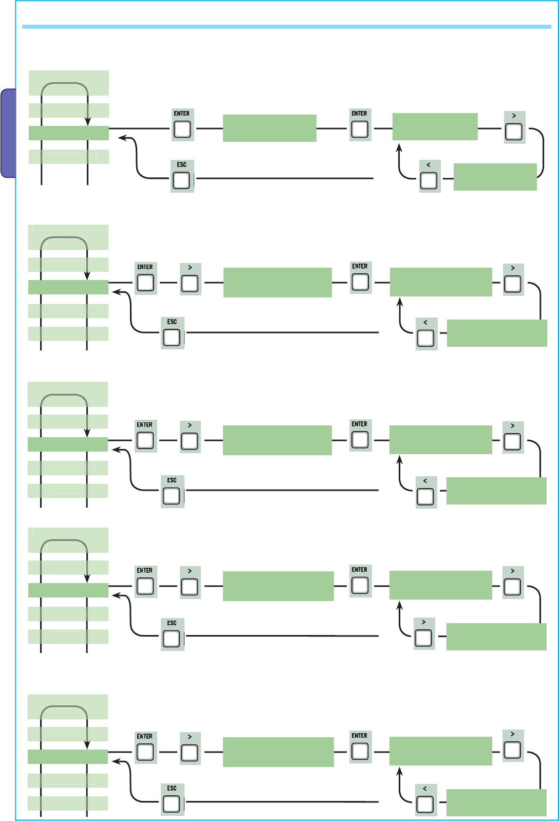
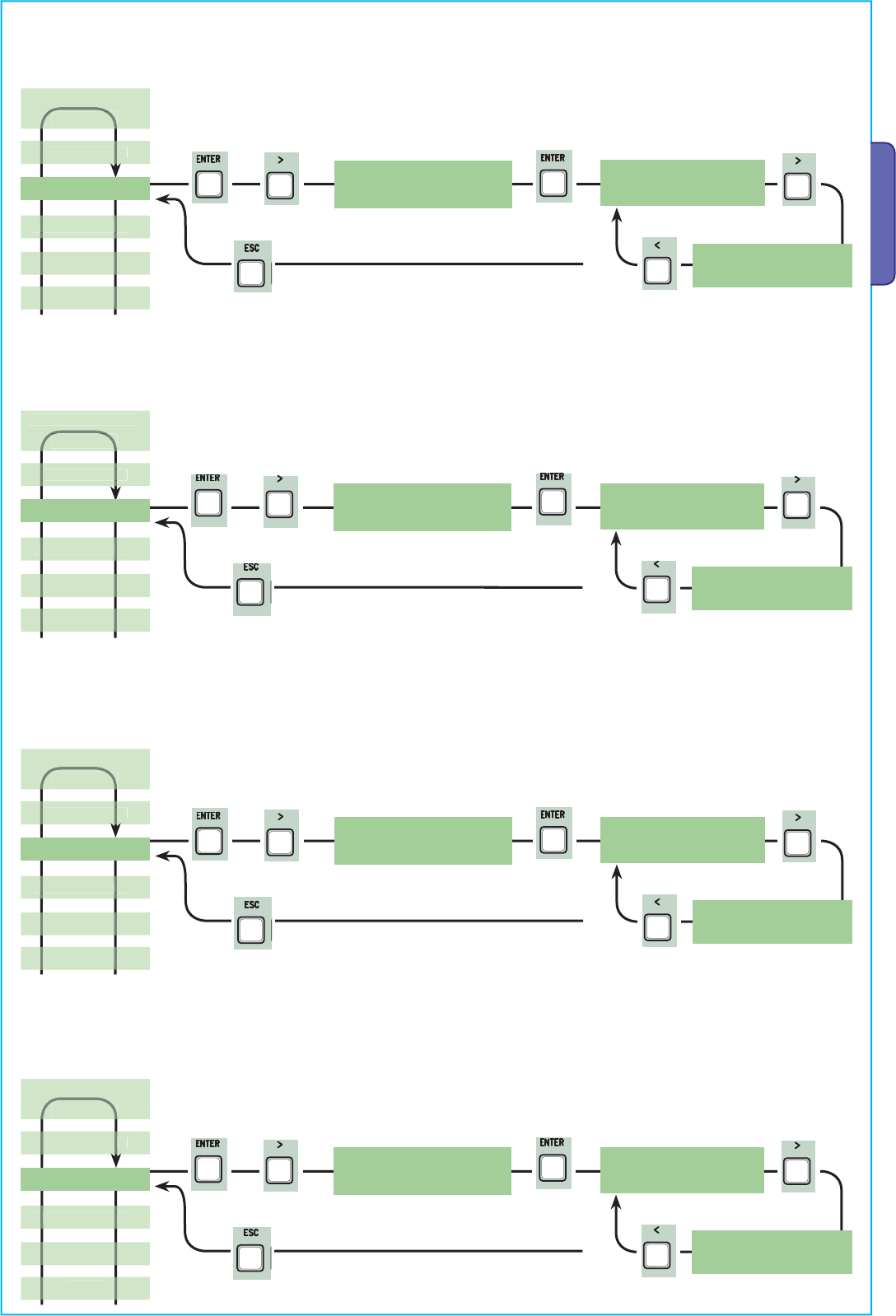
7.2 Browsing the menu
7.1 Description of display commands
The ENTER key is for:
— entering the menu;
— confirming and memorising set values.
The ESC key is for:
— exiting the menu;
— cancelling modifications.
The < > keys are for:
— shifting from one menu item to another;
— increase or decrease values.
the <…> symbols on the display are for:
-pointing out the currently, selected item
LANGUAGE
English
Þß
LANGUAGE
English
Þß
FUNCTIONS
English
Þß
TIMING ADJ.
Þß
A.C.T.
90s
Þß
Cycle Time
90s
Þß
Cycle Time
90s
Þß
Cycle Time
100s
Þß
ENTER
>
ENTER >
ENTER
>
>
ENTER
ENTER
ENTER >
>
>
>
>
>
ENTER
>
>
>
>
>
>
>
>
ENTER
>
>
>
>
>
>
>
>
>
>
>
>
>
>
>
ENTER
>
>
ENTER
>
>
ENTER
>
>
ENTER
>
>
ENTER
>
>
ENTER
>
>
ENTER
>
>
ENTER
>
>
ENTER
>
ENTER
>
>
ENTER
>
>
ENTER
>
>
ENTER
>
>
ENTER
>
>
ENTER
>
>
>
>
>
>
>
ENTER
ENTER
>
>
ESC
Pag.
10 — Manual code:
319U75 ver.
2.0 01/2009 © CAME cancelli automatici s.p.a. — The data and information reported in this installation manual are susceptible to change at any time and without obligation on CAME cancelli automatici s.p.a. to notify users.
ENGLISH
< LANGUAGE > <English><Francais> <Deutsch>
<Espanol><Italian o>
7.3 Menu structure
< TIMING ADJ >
< INFO >
< T.C.A. >
< FUNCTIONS >
< USERS >
Choose User
<001:-U001—>
< 0s. >
< 300s.>
< 0s. >
< 300s.>
< 10s. >
< 150s.>
< 1s. >
< 10s. >
< 1s. >
< 60s >
< 1s. >
< 60s.>
< 1s. >
< 5s. >
< 1s. >
< 10s. >
< 5s. >
< 60s.>
< 0s. >
< 30s.>
Sel.Utente
<002:-U002—>
Choose User
<001:-U001—>
Sel.Utente
<002:-U002—>
Choose User
<001:-U001—>
Sel.Utente
<002:-U002—>
Choose User
<001:-U001—>
Sel.Utente
<002:-U002—>
< TEST MOT. > TEST MOT.
< <=M1 M2=> >
< ENCODER > See detailed functions on pages 17, 18, 19 and 20 (the “ENCODER” function, appears only if
selected from the “Config.” function in the FUNCTIONS menu.
< System Reset >
<Pedestrian ACT>
< Cycle Time >
< Op. Delay M1 >
< Cl. Delay M2 >
<Preflashing T.>
< Lock time >
< Ram hit time >
< Ped.opening >
<Slow down time>
< Add User >
< Mod. name >
< Mod. Code >
<Related Func.>
< Remove Usr. >
<Delete all Usr>
< Backup data >
<Restore backup>
< Standby Msg. >
< Version >
fw. 3.0
< No. of Runs >
16480
confirm? (no)
confirm? (yes)
confirm? (no)
confirm? (yes)
confirm? (no)
confirm? (yes)
confirm? (no)
confirm? (yes)
>
>
>>>
>
>>
>
ENTER
>
ENTER >
>
>
ENTER
>
>
>
>
>
>
>
>
>
>
>
>
>
>
ENTER
>
>
ENTER
>
>
ENTER
>
>
ENTER
>
>
ENTER
>
>>
>
>>
>
ENTER
>
>>
>
>>
>
ENTER
>
>>
>
>>
>
ENTER
>
>
ENTER >
>>
>
ENTER >
>
ENTER >
>
ENTER >
>
ENTER >
>
ENTER >
>
ENTER >
>
ENTER
>
< -ooo+ >
•< -ooo+ >
••
>
>
>
>
>
>
>
>
>
ENTER
>
Pag.
11 — Manual code:
319U75 ver.
2.0 01/2009 © CAME cancelli automatici s.p.a. — The data and information reported in this installation manual are susceptible to change at any time and without obligation on CAME cancelli automatici s.p.a. to notify users.
ENGLISH
<when close>
< Disabled > < Turn on >
< CX >
< CX+CZ >
<CX+CY+CZ> < CX+CY >
< CY > < CZ >
< CY+CZ >
< Config. >
< C1 >
< C7 >
< C8 > < C4 >
< C2 > < C3 >
< Disabled > < C1 >
< C7 >
< C8 > < C4 >
< C2 > < C3 >
< Disabled > < C1 >
< C7 >
< C8 > < C4 >
< C2 > < C3 >
< N.C. > < N.A. >
< M1 + M2 > < M2 >
< encoder >
< Cl. Thrust > < Turn on > < Disabled >
< AutoClose >
<M aintained A ct>
< Obstacle Det. >
< Safety d.Test >
< Preflashing >
< Total Stop >
< CX Input >
< CY Input >
< CZ Input >
<Ram hit funct.>
< Turn on > < Disabled >
< Turn on > < Disabled >
< Disabled >
< Turn on > < Disabled >
< Turn on > < Disabled >
< Turn on > < Disabled >
< Disabled >
< Turn on > < Disabled >
< Slow run > < Fcap—RallCh >
<Limit switch> < Time of Run >
< Lock >
< endstop >
< cmd 2-7 >
< cmd 2-3P >
< lamp E3 >
<output B1-B2>
< No. Motors >
<Slow Down Spd>
<Op.—Stop—Cl.> <Open—Close>
<Pedestrian> < Partial >
< Cycle > < Courtesy >
<Monostable> <Bistable>
X 2
X 2
Pag.
12 — Manual code:
319U75 ver.
2.0 01/2009 © CAME cancelli automatici s.p.a. — The data and information reported in this installation manual are susceptible to change at any time and without obligation on CAME cancelli automatici s.p.a. to notify users.
ENGLISH
LANGUAGE
< English >
LANGUAGE
< Francais >
LANGUAGE
< Deutsch >
LANGUAGE
< Espanol >
LANGUAGE
< Italiano >
7.4 Main menu
Press ENTER
for 1 second
7.5 Language menu
Select language: selects among the languages displayed.
< LANGUAGE >
English
7.6 Functions menu
< AutoClose >
Turn o n
AutoClose
< Turn on >
AutoClose
< Disabled >
Automatic Closing: activates or deactivates the automatic closing function.
The automatic closing timer activates at each opening endpoint. The predetermined time may be adjusted, and is in any case
dependent on any safety devices that may activate; and it does not activate after a total safety “stop” or during a power outage.
< TIMING ADJ. >
Maintained Act
< Disabled >
<M aintained A ct>
Disabled
Maintained action: the gate works by keeping the button pressed (button 2-3 for opening, button 2-4 for closing, or if set to the “On
Closing” function, only with button 2-4.
Maintained Act
< when close >
< USERS >
250
< INFO >
Max. 250 users
< ENCODER >
< TEST MOT. >
It appears only if selected from the “Config.”
Section in the FUNCTIONS menu.
< LANGUAGE >
English
< FUNCTIONS >
FUNCTIONS
FUNCTIONS
Maintained Act
< Turn on >
X 2
X 2
X 4
X 2
X 5
X 2
X 3
X 2
Pag.
13 — Manual code:
319U75 ver.
2.0 01/2009 © CAME cancelli automatici s.p.a. — The data and information reported in this installation manual are susceptible to change at any time and without obligation on CAME cancelli automatici s.p.a. to notify users.
ENGLISH
<Safety d.Tes t>
Disabled
Safety d.Test
< Disabled >
Safety d.Test
< CX >
Safety d.Test
< CY >
Safety d.Test
< CZ >
Safety d.Test
< CX+CY >
Safety d.Test
< CX+CZ >
Safety d.Test
< CX+CY+CZ >
Obstacle Det.
< Disabled >
<Obstacle Det.>
Disabled
Obstacle Det.
< Turn on >
Obstacle detected: when motor is stopped (gate closed or after a total stop command) it prevents any movement if safety devices,
such as photocells, detect any obstacles.
Safety test: allows the card to check the efficiency of any safety devices (i.e. photocells) after every opening or closing command.
Preflashing
< Disabled >
< Preflashing >
Disabled
Pre-flashing: after an opening or closing command, the flashing light, connected to W-E, starts flashing before the gate begins its run
(to set the time, see “Pre-flashing timing” from the Adjust Timings menu
Ram hit funct.
< Disabled >
<Ram hit funct.>
Disabled
FUNCTIONS
FUNCTIONS
NF
FUNCTIONS
LANGUAGE >
FUNCTIONS
Ram blow: before any opening run, the gate leaves will press onto the mechanical endstop for a few seconds, to help release the elec-
trolock (to set the time, see “Starting ram timing” in the Adjust Timings menu).
X 2
X 8
X 2
X 7
X 2
X 6
Pag.
14 — Manual code:
319U75 ver.
2.0 01/2009 © CAME cancelli automatici s.p.a. — The data and information reported in this installation manual are susceptible to change at any time and without obligation on CAME cancelli automatici s.p.a. to notify users.
ENGLISH
< CY Input >
Disabled
CY Input
< Disabled >
CY Input
< C2 >
CY Input
< C3 >
CY Input
< C4 >
CY Input
< C1 >
CY Input
< C7 >
CY Input
< C8 >
CX input: the N.C. safety contact input can take on the following functions: C1 (re-opening when closing), C2 (re-closing when
opening), C3 (partial stop), C4 (obstacle stall), C7 (re-opening when closing, for sensitive edges), C8 (re-closing when opening, for
sensitive edges) or, be deactivated. See safety devices on electrical connections.
< CX Input >
Disabled
CX Input
< Disabled >
CX Input
< C2 >
CX Input
< C3 >
CX Input
< C4 >
CX Input
< C1 >
Total Stop
< Turn on >
< Total Stop >
Turn o n
Total Stop
< Disabled >
Total Stop: this function stops the gate and consequently excludes any automatic closing cycle; for movement to resume, you need to
use the keypad or transmitter. Insert safety device on [1-2]; Insert the safety device on [1 -2]; if unused, select “Deactivated”
CX Input
< C7 >
CX Input
< C8 >
CY input: safety contact input can take on the following functions: C1 (re-opening when closing), C2 (re-closing when opening), C3
(partial stop), C4 (obstacle stall), C7 (re-opening when closing, for sensitive edges), C8 (re-closing when opening, for sensitive edges)
or, be deactivated. See safety devices on electrical connections.
FUNCTIONS
FUNCTIONS
NFO
FUNCTIONS
X 2
X 9
X 2
X 11
X 2
X 10
X 2
X 12
Pag.
15 — Manual code:
319U75 ver.
2.0 01/2009 © CAME cancelli automatici s.p.a. — The data and information reported in this installation manual are susceptible to change at any time and without obligation on CAME cancelli automatici s.p.a. to notify users.
ENGLISH
Lock: to lock the gate leaves. Required for gate leaves longer than 2.50 m.
CZ input: safety contact input can take on the following functions: C1 (re-opening when closing), C2 (re-closing when opening), C3
(partial stop), C4 (obstacle stall), C7 (re-opening when closing, for sensitive edges), C8 (re-closing when opening, for sensitive edges)
or, be deactivated. See safety devices on electrical connections.
Closing thrust: at the endpoint stage during closing, the gearmotors perform a final closing-thrust of the doors for a few seconds.
Cl. Thrust.
< Disabled >
< Cl. Thrust. >
Disabled
Cl. Thrust.
< Turn on >
Config.
< Fcap—RallCh >
Deceleration configuration: configuring decelerations when opening or closing:
— slow run: decelerations when opening and closing;
— Fcap-RallCh.: end stop when opening and deceleration when closing;
— ecoder: managing decelerations, obstacle detection and sensitivity; (FROG-AE)
— Time of Run: timed end stop (default function); (FROG-A, FERNI 230V, ATI 230V, FAST 230V and KRONO)
— Limit switch (endstop): opening and closing endstop. (C-BX and F4000)
Config.
< encoder >
FUNCTIONS
< CZ Input >
Disabled
CZ Input
< Disabled >
CZ Input
< C1 >
CZ Input
< C2 >
CZ Input
< C3 >
CZ Input
< C4 >
CZ Input
< C7 >
CZ Input
< C8 >
Lock
< Disabled >
< Lock >
Disabled
Lock
< Turn on >
FUNCTIONS
FUNCTIONS
FUNCTIONS
USERS
< Config. >
Slow run
Config.
< Slow run >
Config.
<Time of Run>
Config.
<Limit switch>
X 2
X 2
X 2
X 2
X 15
X 16
X 13
X 14
Pag.
16 — Manual code:
319U75 ver.
2.0 01/2009 © CAME cancelli automatici s.p.a. — The data and information reported in this installation manual are susceptible to change at any time and without obligation on CAME cancelli automatici s.p.a. to notify users.
ENGLISH
< endstop >
N.C
endstop
< N.C >
Endstop: configure the endpoints are normally closed or open contacts.
N.B.: this function appears only if selected from the “Config.” function in the FUNCTIONS menu.
< cmd 2-7 >
Op.—Stop-Cl.
cmd 2-7
<Op.—Stop—Cl.>
Command 2—7: setting the 2-7 contact to step-by- step mode (open-close) or sequential (open-stop-close-stop).
endstop
< N.A >
cmd 2-7
<Open—Close>
< cmd 2-3P >
Pedestrian
cmd 2-3P
< Pedestrian >
cmd 2-3P
< Partial >
< lamp E3 >
Cycle
lamp E3
< Cycle >
lamp E3
< Courtesy >
Command 2-3P: setting the 2-3P contact to pedestrian opening (second gate leaf opens fully) or partial (second gate leaf opens
partially depending on the time set on “Partial opening” from the Adjust Times menu).
E3 lamp: configuring the lamp connected to E-E3:
— cycle: outdoor lamp, which can be positioned at leisure, for better illumination in the parking/driveway area.
It stays on from the moment the gate leaf begins to open, until it is fully closed (including automatic closing time).
In case the automatic closing function is not inserted, it stays on only during gate movement.
— courtesy: outdoor lamp, which can be positioned at leisure, for better illumination in the parking/driveway area.
It stays on for a set time of 5 minutes.
FUNCTIONS
FUNCTIONS
< LANGUAGE >
FUNCTIONS
FUNCTIONS
X 2
X 2
X 2
X 19
X 17
X 18
X 2
Pag.
17 — Manual code:
319U75 ver.
2.0 01/2009 © CAME cancelli automatici s.p.a. — The data and information reported in this installation manual are susceptible to change at any time and without obligation on CAME cancelli automatici s.p.a. to notify users.
ENGLISH
< output B1-B2 >
Monostable
output B1-B2
< Bistable >
B1-B2 output: setting contact B1—B2 to MONO-STABLE or BI-STABLE (switch) mode.
< No. Motors >
M1 + M2
No. Motors
< M1 + M2 >
Number of motors: setting the number of motors, either one or two, depending on the number of gate leaves installed on the system.
Slow Down: setting the deceleration speed when opening or closing, or, only when closing if said deceleration is configured as (Fcap—
RallCh.).
N.B.: this function only appears if the decelerations are selected.
output B1-B2
< Monostable
No. Motors
< M2 >
<Slow Down Spd.>
-ooo+ •
Slow Down Spd.
< -ooo+ >
FUNCTIONS
FUNCTIONS
FUNCTIONS
•
Slow Down Spd.
< -ooo+ >
•
••
Motor Type: setting up the type of swing gate motor installed in the system.
< Motor Type >
FROG
Motor Type
< FROG >
Motor Type
< AXO >
Motor Type
< FAST >
FUNCTIONS
X 2
X 2
X 3
X 2
X 4
X 2
X 2
X 2
Pag.
18 — Manual code:
319U75 ver.
2.0 01/2009 © CAME cancelli automatici s.p.a. — The data and information reported in this installation manual are susceptible to change at any time and without obligation on CAME cancelli automatici s.p.a. to notify users.
ENGLISH
<Sensib. Decel.>
-oooooooo+
Sensib. Decel.
< -oooooooo+ >
Sensib. Decel.
< -oooooooo+ >
Deceleration sensitivity: it adjusts the obstacle detection sensitivity during opening and closing gate deceleration.
N.B.: this function appears only if the “sensitivity” function is activated in the ENCODER menu.
•
•
••
< Slow run Enc >
ON
Slow run Enc
< ON >
Slow run Enc
< OFF >
Encoder Deceleration: this activates the opening and closing deceleration starting points.
< M1 Slow.AP.% >
10
M1 Slow.AP.%
< 10 >
M1 Slow.AP.%
< 11 >
M1 opening deceleration%: this adjusts the (M1) first motor’s deceleration starting point before the opening endpoint.
The deceleration starting point is calculated as a percentage (from 1% to 40% of a full gate run). See illustration on page 28.
N.B.: this function appears only if it is activated in the “decel. Enc” function in the ENCODER menu.
< Sensib. Run >
-oooooooo+
Sensib. Run
< -oooooooo+ >
Sensib. Run
< -oooooooo+ >
•
•
••
ENCODER
ENCODER
< LANGUAGE >
ENCODER
ENCODER
Gate operation sensitivity: this adjusts the obstacle detection sensitivity during opening and closing gate operation.
N.B.: this function appears only if the “sensitivity” function is activated in the ENCODER menu.
< Sen sibility >
Turn o n
Sensibility
< Turn on >
Sensibility
<Disabled>
7.7 Encoder Menu (the ENCODER menu, appears only if selected from the “Config.” function in the FUNCTIONS menu.)
Sensitivity: the obstacle detection function is activated during gate operation and deceleration.
N.B.: before setting the functions in the encoder menu, run the gearmotor checks to verify the proper turning direction.
ENCODER
X 5
X 2
X 6
X 2
X 7
X 2
X 8
X 2
Pag.
19 — Manual code:
319U75 ver.
2.0 01/2009 © CAME cancelli automatici s.p.a. — The data and information reported in this installation manual are susceptible to change at any time and without obligation on CAME cancelli automatici s.p.a. to notify users.
ENGLISH
< M1 Slow.CH % >
10
M1 Slow.CH %
< 10 >
M1 Slow.CH %
< 11 >
M1 closing deceleration%: this adjusts the (M1) first motor’s deceleration starting point before the closing endpoint.
The deceleration starting point is calculated as a percentage (from 1% to 40% of a full gate run). See illustration on page 28.
N.B.: this function appears only if it is activated in the “decel. Enc” function in the ENCODER menu.
< M2 Slow.AP % >
10
M2 Slow.AP %
< 10 >
M2 Slow.AP %
< 11 >
M2 opening deceleration%: this adjusts the (M2) second motor’s deceleration starting point before the opening endpoint.
The deceleration starting point is calculated as a percentage (from 1% to 40% of a full gate run). See illustration on page 28.
N.B.: this function appears only if it is activated in the “decel. Enc” function in the ENCODER menu.
< M2 Slow.CH % >
10
M2 Slow.CH %
< 10 >
M2 Slow.CH %
< 11 >
M2 closing deceleration %: this adjusts the (M2) second motor’s deceleration starting point before the closing endpoint.
The deceleration starting point is calculated as a percentage (from 1% to 40% of a full gate run). See illustration on page 28.
N.B.: this function appears only if it is activated in the “decel. Enc” function in the ENCODER menu.
< M1 Appr.CH % >
5
M1 Appr.CH %
< 5 >
M1 Appr.CH %
< 6 >
M1 closing acceleration %: this adjusts the (M1) first motor’s percentage rate of approach to the final closing and opening points
before reaching the opening and closing endpoints. The percentage rate of approach to (goes from 1% to 15% of the full gate run). See
illustration on page 28.
ENCODER
NF
ENCODER
ENCODER
ENCODER
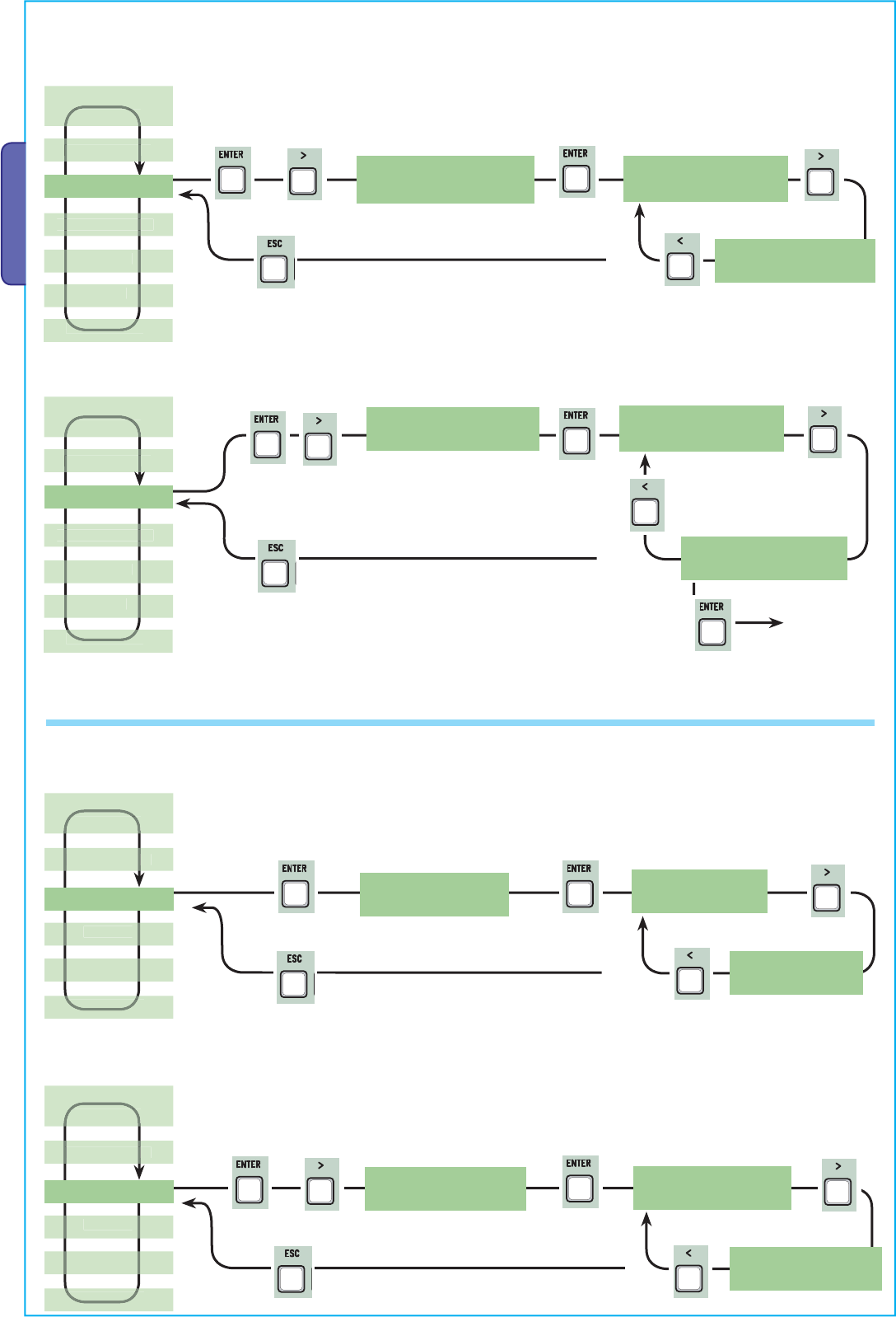
X 2
X 2
X 8
X 2
X 9
X 2
Pag.
20 — Manual code:
319U75 ver.
2.0 01/2009 © CAME cancelli automatici s.p.a. — The data and information reported in this installation manual are susceptible to change at any time and without obligation on CAME cancelli automatici s.p.a. to notify users.
ENGLISH
<Pedestrian ACT>
10s.
Pedestrian ACT
< 10s. >
Pedestrian ACT
< 11s. >
Automatic Pedestrian Closing: waiting time of the (M2) second gate leaf when in the open position. Once this time interval has
elapsed, the gate automatically closes. The waiting time interval can go anywhere from 0” to 300”.
< M2 Appr.CH % >
5
M2 Appr.CH %
< 5 >
M2 Appr.CH %
< 6 >
M2 closing acceleration %: this adjusts the (M2) second motor’s percentage rate of approach to the final closing and opening points
before reaching the opening and closing endpoints. The percentage rate of approach to (goes from 1% to 15% of the full gate run). See
illustration on page 28.
< Set Encoder > Set Encoder
<confirm?(no)>
Set Encoder
<confirm?(yes)>
< A.C.T. >
10s.
A.C.T.
< 10s. >
A.C.T.
< 11s. >
7.8 Time setting menu
Automatic closing: to set the waiting time when gate is in the open position.
Once this time is elapsed, the gate closes automatically. The waiting time can be set to between 0” and 300”.
ENCODER
TIMING ADJ.
TIMING ADJ.
See detailed
description on
page 28
ENCODER
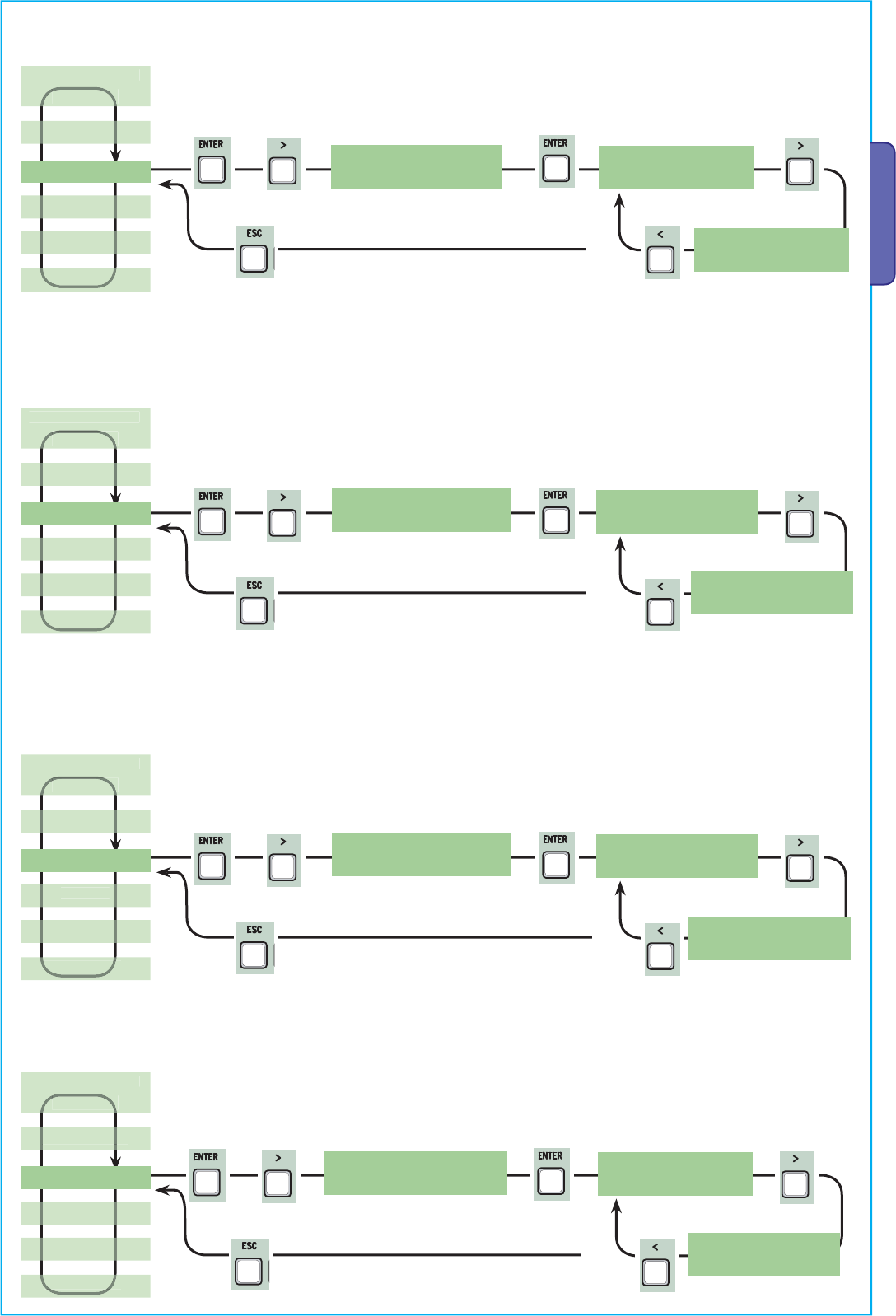
X 2
X 2
X 2
X 3
X 2
X 4
X 2
X 5
Pag.
21 — Manual code:
319U75 ver.
2.0 01/2009 © CAME cancelli automatici s.p.a. — The data and information reported in this installation manual are susceptible to change at any time and without obligation on CAME cancelli automatici s.p.a. to notify users.
ENGLISH
< Cycle Time >
90s.
Cycle Time
< 90s. >
< Op. Delay M1 >
2s
Op. Delay M1
< 2s >
M1 delayed opening: the waiting time of the (M1) first gate lead, unlike the (M2) second one, after each opening command. The
waiting time can be set to between 0” and 10”.
Cycle time: the working time of the motor during opening or closing phases is anywhere from 10” to 150”.
Cycle Time
< 91s. >
Op. Delay M1
< 3s >
< Cl. Delay M2 >
2s
Cl. Delay M2
< 2s >
M2 delayed closing: the waiting time of the (M2) second gate leaf, unlike the (M1) first one, after each closing command. the waiting
time can be set to between 0” and 60”.
Cl. Delay M2
< 3s >
<Preflashing T.>
5s.
Preflashing T.
< 5s. >
Pre-flashing time: after an opening or closing command is given, the flasher connected to “W-E), flashes for between 1” and 60”,
before the gate begins to move.
Preflashing T.
< 6s. >
TIMING ADJ.
NFO
TIMING ADJ.
LANGUAGE >
TIMING ADJ.
SER
TIMING ADJ.
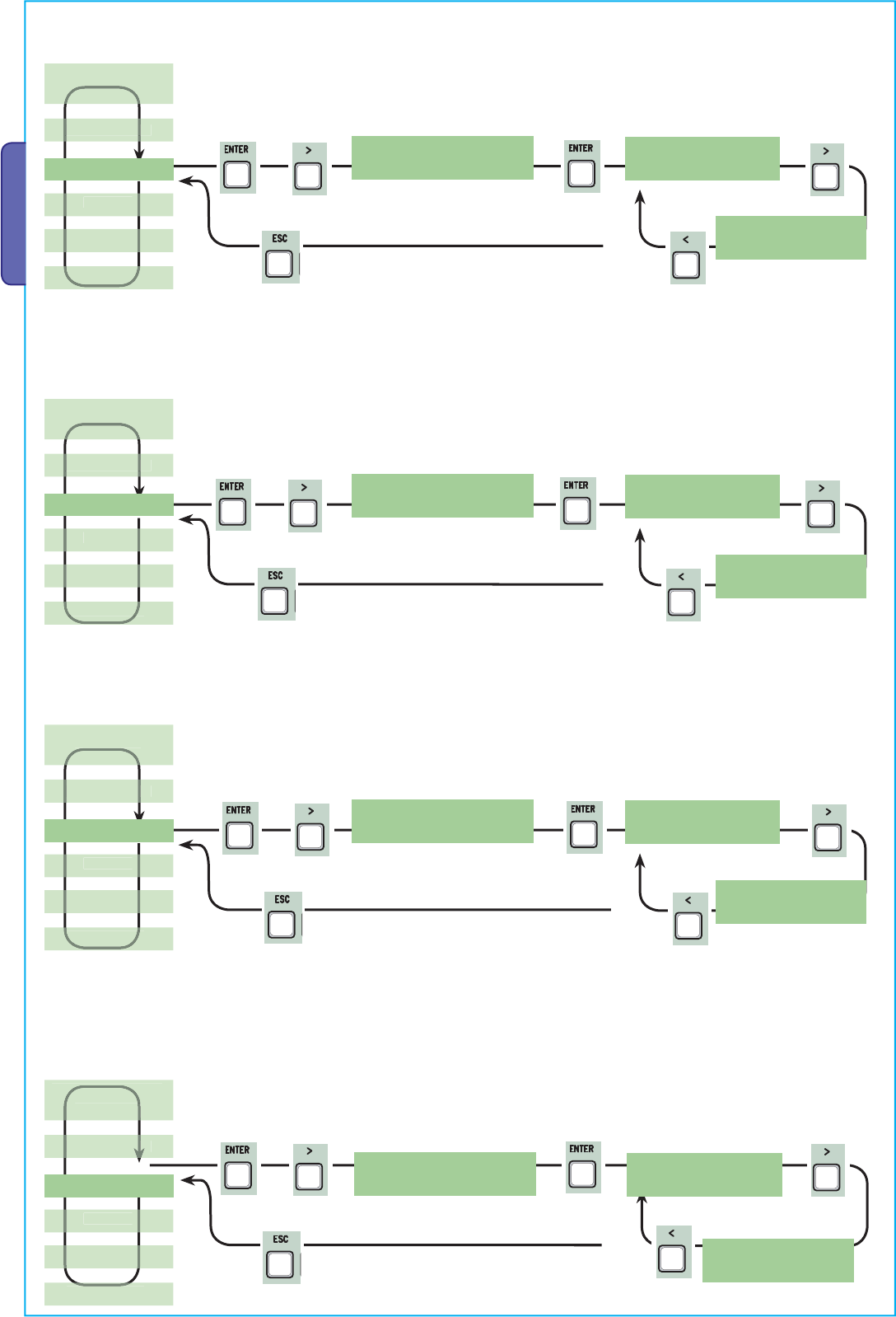
X 2
X 6
X 2
X 7
X 2
X 8
X 2
X 9
Pag.
22 — Manual code:
319U75 ver.
2.0 01/2009 © CAME cancelli automatici s.p.a. — The data and information reported in this installation manual are susceptible to change at any time and without obligation on CAME cancelli automatici s.p.a. to notify users.
ENGLISH
< Lock time >
2s.
Lock time
< 2s. >
Lock time: the time required for releasing the electro-lock after each opening command. The time of operation can be set to between
1” and 5”.
Lock time
< 3s. >
< Ram hit time >
2s.
Ram hit time
< 2s. >
Ram hit time: the gearmotor’s thrust time when fully closing after each opening command. The thrust time can be set to between 1”
and 10”.
Ram hit time
< 3s. >
< Ped. opening >
5s.
Ped. opening
< 5s. >
Partial opening: the opening time of the (M2) second gate leaf. The time can be set to between 5” and 60”.
Ped. opening
< 6s. >
< Slow down time >
5s.
Slow down time
< 5s. >
Slow down time: the gate leaf’s deceleration time before every endpoint. The time can be set to between 0” and 30”.
N.B.: this function only appears if the decelerations are selected.
TIMING ADJ.
TIMING ADJ.
NFO
TIMING ADJ.
TIMING ADJ.
Slow down time
< 6s. >
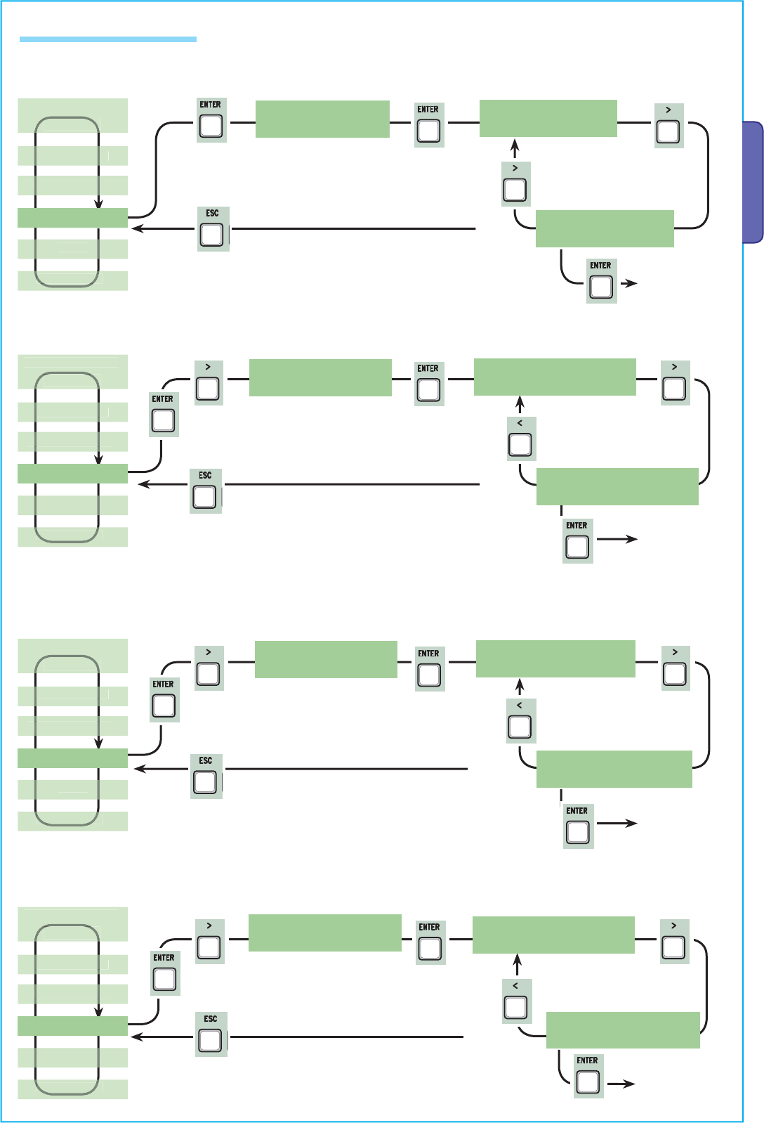
X 2
X 2
X 2
X 2
X 3
X 2
Pag.
23 — Manual code:
319U75 ver.
2.0 01/2009 © CAME cancelli automatici s.p.a. — The data and information reported in this installation manual are susceptible to change at any time and without obligation on CAME cancelli automatici s.p.a. to notify users.
ENGLISH
7.9 Users Radio Menu
< Add User > Add User
<confirm? (no) >
Add User: to create a new user and assigned function (max. 250 users).
< Mod. name > Choose User
< 001:—001— >
Mod. Name: to change a user number or existing name to another name.
< Mod. Code > Choose User
< 001:—001— >
Mod. Code: to change a user’s current code.
Choose User
< 002:—002— >
Add User
<confirm? (yes)>
See detailed
description on
page 26
Choose User
< 002:—002— >
See detailed
description on
page 26
See detailed
description on
page 27
< Related Func >
Choose User
< 002:—002— >
Choose User
< 001:—001— >
See detailed
description on
page 27
USERS
USERS
LANGUAGE >
USERS
USERS
Related Function: to change the function assigned to the user.
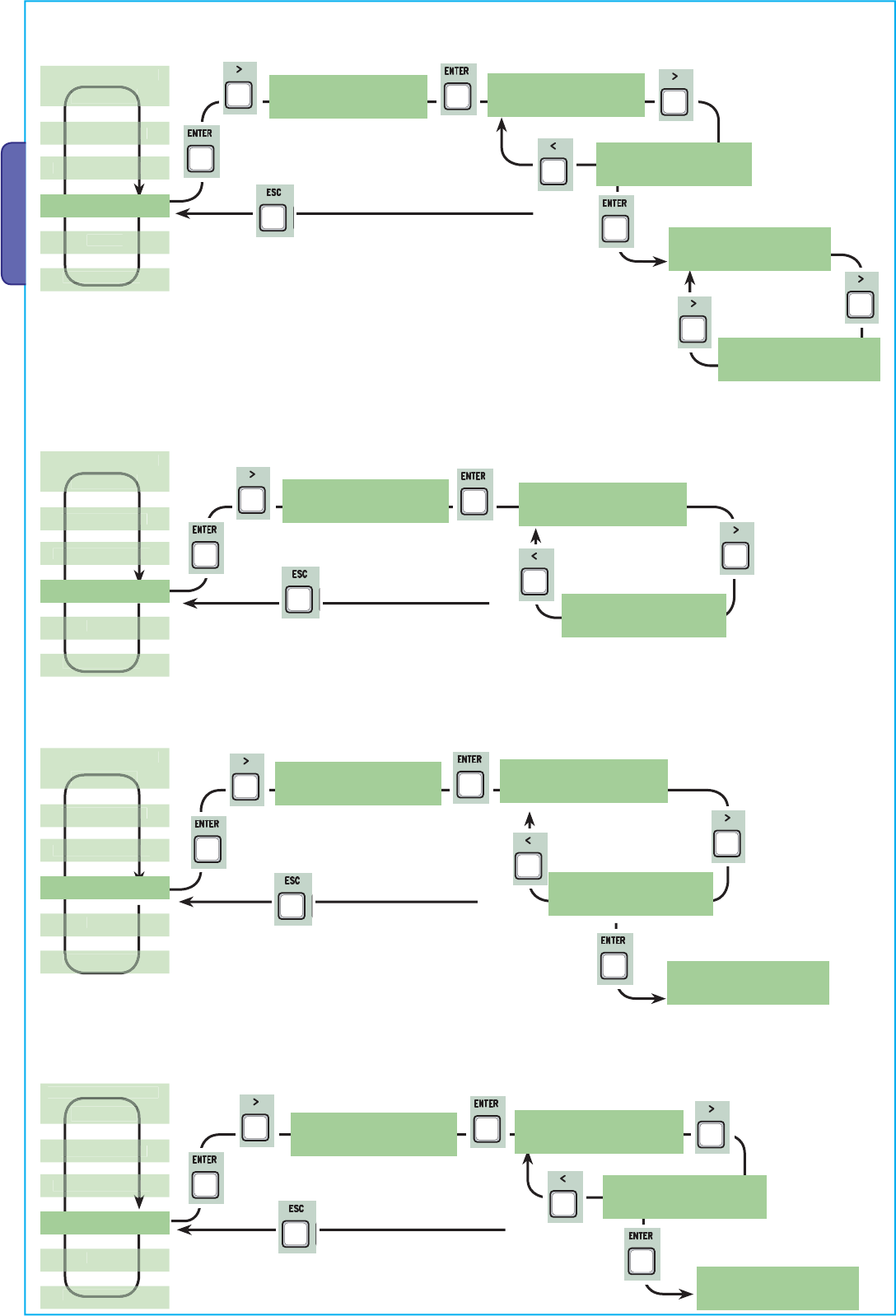
X 2
X 4
X 2
X 5
X 2
X 6
X 2
X 7
Pag.
24 — Manual code:
319U75 ver.
2.0 01/2009 © CAME cancelli automatici s.p.a. — The data and information reported in this installation manual are susceptible to change at any time and without obligation on CAME cancelli automatici s.p.a. to notify users.
ENGLISH
Backup data
<confirm? (no) >
Backup data
<confirm? (yes)>
< Remove Usr. > Choose User
< 001:—001— >
Remove user: to remove an exisiting user. Confirm the use you wish to remove with the ENTER key.
< Backup data >
Backup data: to save the users in the memory roll. Confirm saving of users on the memory roll with ENTER.
Delete all user: to cancel all registered users. Confirm cancellation of all users with ENTER.
Choose User
< 002:—002— >
Remove Usr.
<confirm? (no) >
Remove Usr.
<confirm? (yes)>
<D elete all Usr> Delete all Usr
<confirm? (no) >
Delete all Usr
<confirm? (yes)>
Backup data
WRITE:250
Restore backup: to load the data saved on the memory roll onto card.
Restore backup
<confirm? (no) >
Restore backup
<confirm? (yes)>
<Restore backup>
Restore backup
READ:250
USERS
USERS
USERS
USERS
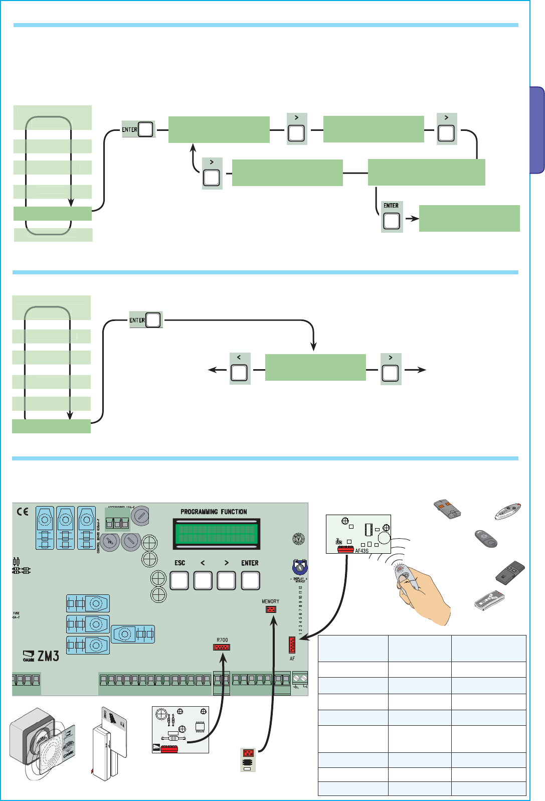
Lingua
Italiano
Þß
CANCELLI AUTOMATICI
R700
ACCESS CONTROL
TOP
TSP00 LT001
CAME
TAM
ATOMO
TWIN
TOUCH
TFM
Memory roll
Pag.
25 — Manual code:
319U75 ver.
2.0 01/2009 © CAME cancelli automatici s.p.a. — The data and information reported in this installation manual are susceptible to change at any time and without obligation on CAME cancelli automatici s.p.a. to notify users.
ENGLISH
Frequency/MHz Card Transmitter
FM 26.995 AF130 TFM
FM 30.900 AF150 TFM
AM 26.995 AF26 TOP
AM 30.900 AF30 TOP
AM 433.92 AF43S TAM / TOP
ATOMO / TWIN
AM 433.92 AF43TW TWIN
AM 40.685 AF40 TOUCH
AM 868.35 AF868 TOP
7.10 nfo Menu
< Version >
fw : 3.0
Version: to view software version.
Number of gate runs: to view the number of runs performed by the gate.
Starting Mssg: to view the starting message, confirm with ENTER to change text. Use the ENTER key to move the cursor forward, ESC
to move it backwards and <> to select the letter of number. Confirm the text by pressing the ENTER key for a few seconds.
System reset: it resets the system to its original settings. Press ENTER key to confirm.
INFO — WWW.CAME.IT
ZM3E
7.11 Motor test menu
TEST MOT.: Test to check the proper direction of the gearmotors.
TEST MOT.
Gate leaf opening run
of the second (M2)
gearmotor. If the
direction is wrong,
invert the motor’s
phases.
Gate leaf opening
run of the first (M1)
gearmotor. If the
direction is wrong,
invert the motor’s
phases.
< TEST MOT. >
<=M1 M2=>
< System Reset >
7.12 Decoding card
Connect the required (R700, AF43S cards) to insert, change, remove and command the operator via transmitter, card or transponder.
Insert the memory roll to save and load all setting including users registered by another card.
AF Card
R700 Card
< No. of Runs >
10
< Standby Msg. >
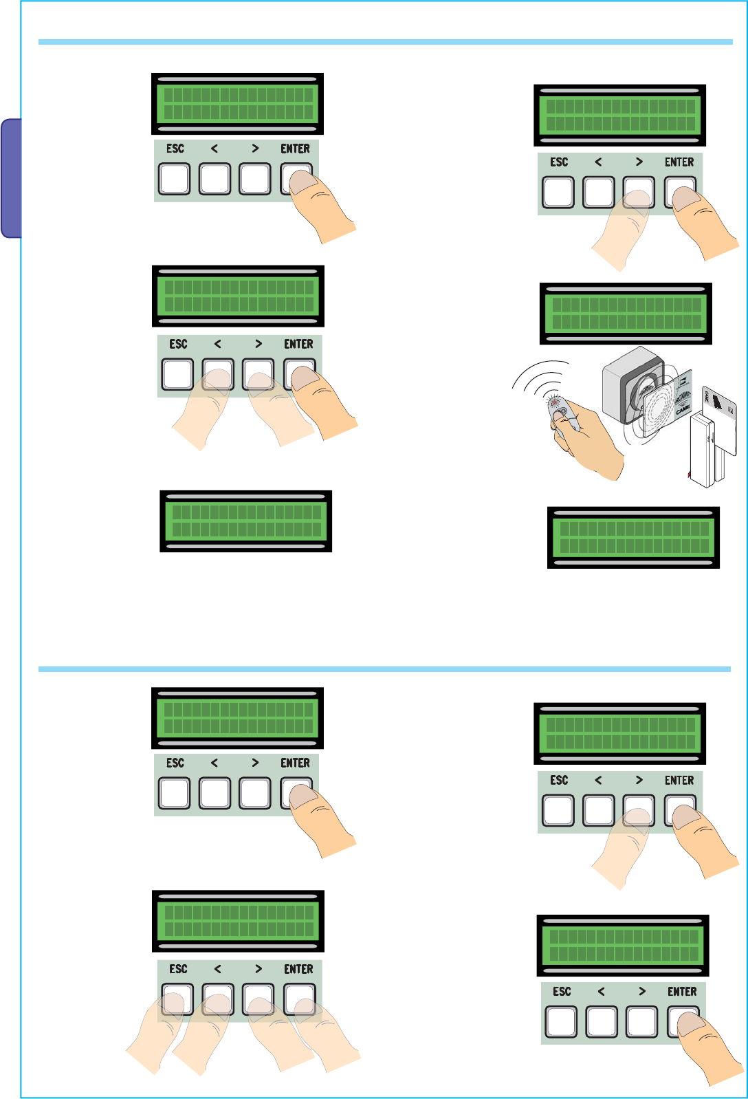
ACCESS CONTROL
Pag.
26 — Manual code:
319U75 ver.
2.0 01/2009 © CAME cancelli automatici s.p.a. — The data and information reported in this installation manual are susceptible to change at any time and without obligation on CAME cancelli automatici s.p.a. to notify users.
ENGLISH
7.13 Inputting users
Add User
Þß
Add User
confirm? (yes)
Þß
1) From the Users
menu, select “Add
User”.
Press ENTER to
confirm.
2) Select “ confirm
(yes)” and press
ENTER key to confirm.
—001—
radio
4) …. will ask to input
a code. Send the
code with the radio-
command button or
slide-through card or
transponder.
5) … once the code
is inputted, the user
name will come up
showing the type of
command that was
memorised…
Code exist
001:—001—
… or if the code is
already inputted,
“Existing Code” will
appear.
3) Choose which
function to assign to
the user….
Related Func.
2-7
Þß
Waiting Code
>>>>
7.14 Changing users
Mod. name
Þß
Choose User
001:—U001—
Þß
1) From the Users
menu, choose
“Mod. name”.
Press ENTER to
confirm.
2) Choose the user
number or name you
wish to change the
text of and press
ENTER to confirm.
4) Confirm the text by
pressing the ENTER key
for a few seconds.
3) Use the ENTER
key to move the
cursor forward, ESC
to move it backwards
and < > to select the
letter or number.
Mod. name
—001— Mod. name
JOHN
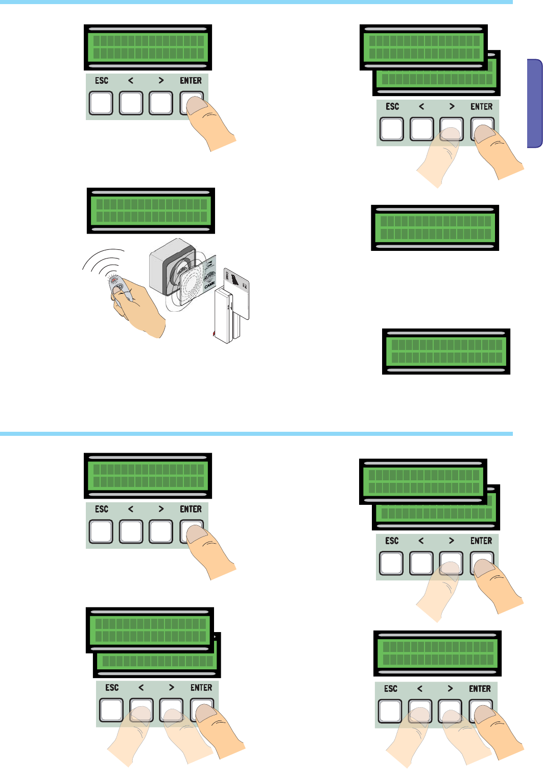
ACCESS CONTROL
Pag.
27 — Manual code:
319U75 ver.
2.0 01/2009 © CAME cancelli automatici s.p.a. — The data and information reported in this installation manual are susceptible to change at any time and without obligation on CAME cancelli automatici s.p.a. to notify users.
ENGLISH
7.15 Changing code
Mod. Code
1) From the Users
menu, choose
“Mod. Code”.
Press ENTER to
confirm.
2) Choose the user
name for which you
wish to change the
code and press ENTER
to confirm.
4) .. once the code
is inputted, the user
name will come up
showing the type of
command that was
memorised…
3) …. you will be
asked to input a
code. Send the code
using the transmitter
button or the slide —
through card or the
transponder.
—002—
radio
7.16 Function assigned to the user
Related Func.
Þß
1) From the Users
menu, choose
“Related Fuc.”.
Press ENTER to
confirm.
2) Choose the user
name fo which you
wish to change the
command function
and press ENTER to
confirm.
4) Choose “confirm
(yes)” and press
ENTER to confirm.
3) Choose the new
function to assign
to the user. Press
ENTER to confirm.
Choose User
002:—U002—
Þß
Related Func.
confirm? (yes)
Þß
Choose User
001:—U001—
Þß
Related Func.
open
Þß
Related Func.
2-7
Þß
Choose User
002:—U002—
Þß
Choose User
001:—U001—
Þß
Mod. Code
confirm? (yes)
Þß
Waiting Code
>>>>
5) Select “ confirm (yes)”
and press ENTER key to
confirm.
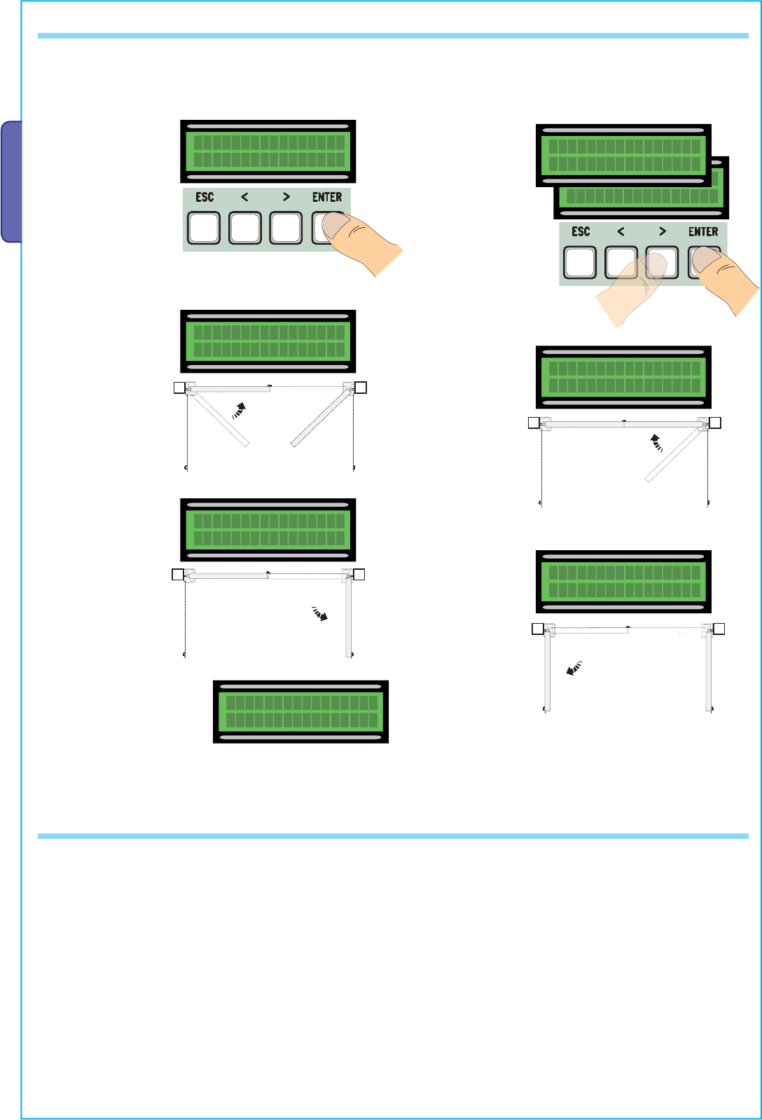
0
0
0
0
0
0
0
0
Pag.
28 — Manual code:
319U75 ver.
2.0 01/2009 © CAME cancelli automatici s.p.a. — The data and information reported in this installation manual are susceptible to change at any time and without obligation on CAME cancelli automatici s.p.a. to notify users.
ENGLISH
7.17 Gate run calibration
Set Encoder
Þß
1) From the Encoder
menu, select “Set
Encoder”. Press ENTER
to confirm.
2) Select “confirm
(yes) and press ENTER
to confirm.
3) the gate leaf of the
first motor will perform
a closing run until fully
closed…..
Set Encoder
confirm? (yes)
<>
Set Encoder
confirm? (no)
Þß
Set Encoder
Close 1 4) …then, the
gate leaf of the
second motor will
perform the same
manoeuvre…
5) …then, the gate leaf
of the second motor, will
perform and opening run
until fully open… 6) …after which,
the gate leaf of
the first motor will
perform the same
manoeuvre…
7) When the procedure is
finished, the display will show
“Set Encoder ok” for a few
seconds.
Set Encoder
Close 2
Set Encoder
Open 2
Set Encoder
Open 1
Set Encoder
OK
N.B. before calibrating the gate run, check that the manoeuvring area is free of any obstacles and check the proper direction of rotation of the
gearmotors. (para. 7.11)
7.18 Error messages
—“encoder ERROR”: check proper connections or functionality of the device and possibly even the motor’s torque”
—“safety d. test ERROR”: malfunctioning of safety devices, check proper functioning of connections and functionalities;
—“end stop ERROR”: check proper connections on end point connections or functionality of devices;
—“cycle time ERROR”: check the working time settings, the set time may be insufficient to complete the duty cycle.
— Safety STOP, C1, C3, C4”: check proper functioning of connections and functionalities of devices.
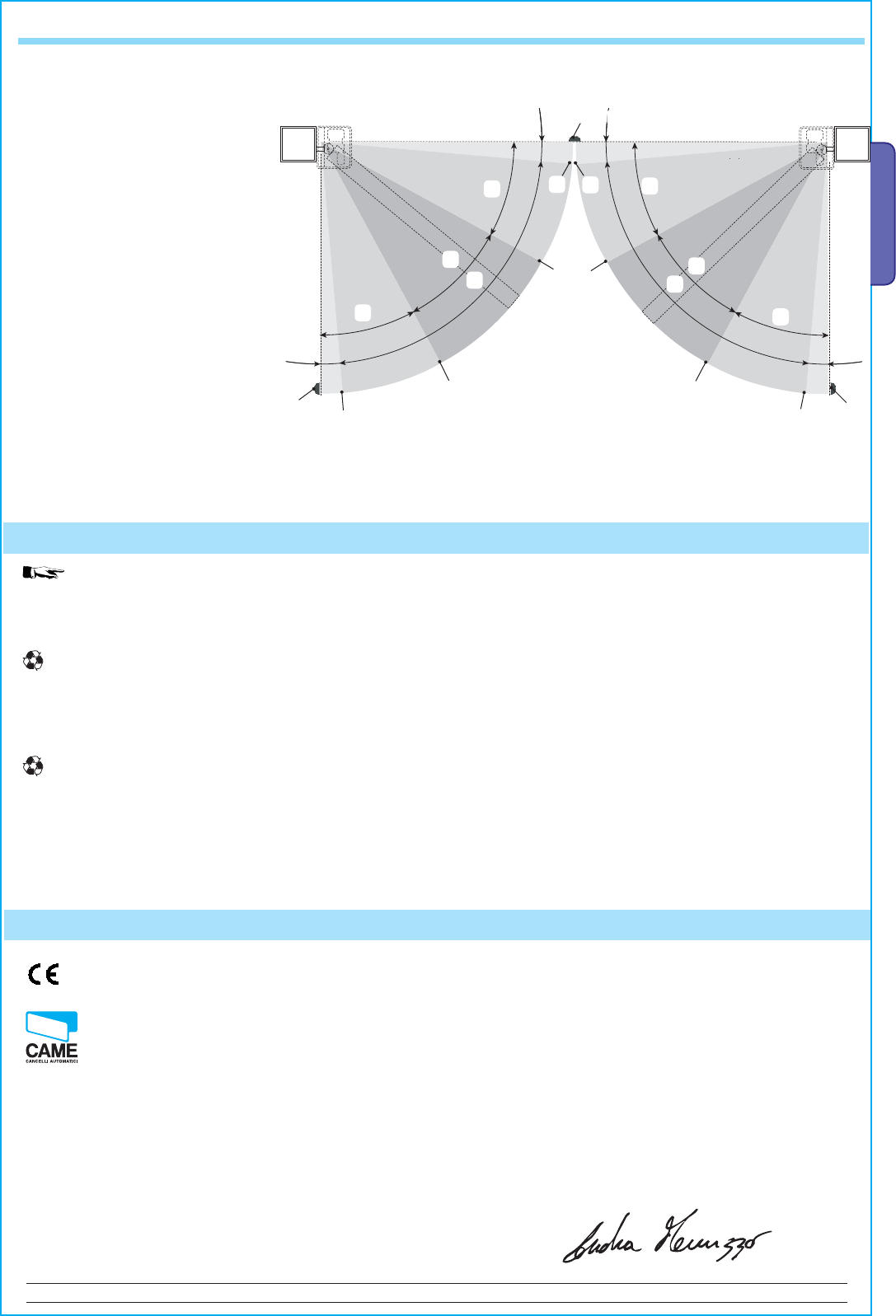
0
0
D
B
A
B
D
B
B
D
A
D
E
F H
G
IL
M
M
M
CC
IL
Pag.
29 — Manual code:
319U75 ver.
2.0 01/2009 © CAME cancelli automatici s.p.a. — The data and information reported in this installation manual are susceptible to change at any time and without obligation on CAME cancelli automatici s.p.a. to notify users.
ENGLISH
7.19 Illustration depicting the areas and points of deceleration and final opening and closing approaches per encoder device.
A = Area of movement at normal speed
B* = Run zone at decelerated speed
C = Encoder intervention zone with
movement inversion
D= Encoder intervention zone with
movement stop
E = Opening deceleration beginning point
(M1 Open Deceler %)
F = Closing deceleration beginning point
(M1 Close Deceler %)
G = Opening deceleration beginning point
(M2 Open Deceler %)
H = Closing deceleration beginning point
(M2 Close Deceler %)
I** = Closing and opening fi nal phase
beginning point (M1 Final Close %)
L** = Closing and opening fi nal phase
beginning point (M2 Final Close %)
M= endstops
Note: the areas and points of deceleration and fi nal opening and closing approaches are tested according to the parameters set forth by
Technical Norms EN12445 and EN12453 regarding compatibility of impact forces generated by moving gate leaves.
* Minimum 600 mm from the Final full stop.
**Set the function’s fi nal phase % “M1 Final Close” for the fi rst (M1) mtors and “M2 Final Close” for the second (M2) motor from the
“ENCODER” menu so as to obtain a distance of between 1 and 50 mm maximum from the fi nal full stop.
In its premises, CAME CANCELLI AUTOMATICI S.p.A. implements an Environmental Management System certifi ed in
compliance with the UNI EN ISO 14001 standard to ensure environmental protection.
Please continue our efforts to protect the environment—which CAME considers one of the cardinal elements in the development of its
operational and market strategies—simply by observing brief recommendations as regards disposal:
DISPOSAL OF PACKAGING
The packaging components (cardboard, plastic, etc.) are all classifi able as solid urban waste products and may be disposed of easily,
keeping in mind recycling possibilities.
Prior to disposal, it is always advisable to check specifi c regulations in force in the place of installation.
PLEASE DISPOSE OF PROPERLY!
PRODUCT DISPOSAL
Our products are made up of various types of materials. Most of them (aluminium, plastics, iron, electrical wires, etc.) may be disposed
of in normal garbage collection bins and can be recycled by disposing of in specifi c recyclable material collection bins and disposal in
authorized centres. Other components (electrical boards, remote control batteries, etc.), however, may contain polluting substances.
They should therefore be removed and given to qualifi ed service companies for proper disposal.
Prior to disposal, it is always advisable to check specifi c regulations in force in the place of disposal.
PLEASE DISPOSE OF PROPERLY!
8 Demolition and disposal
MANUFACTURER’S DECLARATION OF CONFORMITY
Pursuant to the Low Voltage Directive 2006/95/EC
CAME Cancelli Automatici S.p.A.
via Martiri della Libertà, 15
31030 Dosson di Casier — Treviso — ITALY
tel (+39) 0422 4940 — fax (+39) 0422 4941
internet: www.came.it — e-mail: info@came.it
Declares under its own responsibility that the equipments for automatic garage doors and gates listed below:
… comply with the National Law related to the following European Directives and to the applicable parts of the
following Standards.
2006/95/EC LOW VOLTAGE DIRECTIVE
2004/108/EC ELECTROMAGNETIC COMPATIBILITY DIRECTIVE
EN 60335-1 EN 61000-6-2
EN 13241-1 EN 61000-6-3
IMPORTANT WARNING!
Do not use the equipment specifi ed here above, before
completing the full installation
In full compliance with the Machinery Directive 98/37/EC
MANGING DIRECTOR
Mr. Andrea Menuzzo
ZM3E — ZM3EC
9 Manufacturer’s warranty
Reference code to request a true copy of the original: DDF L EN Z002e
CAME France S.a.
7, Rue Des Haras
Z.i. Des Hautes Patures
92737
Nanterre Cedex — FRANCE
(+33) 1 46 13 05 05
(+33) 1 46 13 05 00
CAME Gmbh Seefeld
Akazienstrasse, 9
16356
Seefeld
Bei Berlin — DEUTSCHLAND
(+49) 33 3988390
(+49) 33 39883985
CAME Automatismes S.a.
3, Rue Odette Jasse
13015
Marseille — FRANCE
(+33) 4 95 06 33 70
(+33) 4 91 60 69 05
CAME Gmbh
Kornwestheimer Str. 37
70825
Korntal
Munchingen Bei Stuttgart — DEUTSCHLAND
(+49) 71 5037830
(+49) 71 50378383
CAME Automatismos S.a.
C/juan De Mariana, N. 17-local
28045
Madrid — SPAIN
(+34) 91 52 85 009
(+34) 91 46 85 442
CAME Americas Automation Llc
CAME Americas Automation Llc
1560 Sawgrass Corporate Pkwy, 4th Floor
Sunrise, FL 33323 — U.S.A
(+1) 305 433 3307
(+1) 305 396 3331
CAME Automatismos Catalunya S.a.
CAME Automatismos Catalunya S.a.
P.i. Moli Dels Frares N. 23 C/a
08620
Sant Vicenc Del Horts — SPAIN
(+34) 93 65 67 694
(+34) 93 67 24 505
CAME Middle East Fzco
Po Box 17131 Warehouse N. Be02
South Zone — Jebel Ali Free Zone —
Dubai — U.A.E.
(+971) 4 8860046
(+971) 4 8860048
Paf — CAME
Estrada Nacional 249-4 Ao Km 4,35
Cabra Figa — Trajouce
2635-047
Rio De Mouro — PORTUGAL
(+351) 219 257 471
(+35) 219 257 485
CAME Polska Sp.Zo.o
Ul. Ordona 1
01-237
Warszawa — POLAND
(+48) 22 8365076
(+48) 22 8363296
CAME United Kingdom Ltd.
Unit 3 Orchard Business Park
Town Street, Sandiacre
Nottingham — Ng10 5du — UNITED KINGDOM
(+44) 115 9210430
(+44) 115 9210431
S.c. CAME Romania S.r.l.
B-dul Mihai Eminescu, Nr. 2, Bloc R2
Scara A, Parter, Ap. 3
Buftea, Judet Ilfov
Bucarest — ROMANIA
(+40) 21 3007344
(+40) 21 3007344
CAME Belgium Sprl
Zoning Ouest 7
7860
Lessines — BELGIUM
(+32) 68 333014
(+32) 68 338019
CAME Russia
Leningradskij Prospekt, Dom 80
Pod’ezd 3, offi ce 608
125190,
Moskva — RUSSIA
(+7) 495 937 33 07
(+7) 495 937 33 08
CAME Cancelli Automatici S.p.a.
CAME Cancelli Automatici S.p.a.
Via Martiri Della Libertà, 15
31030
Dosson Di Casier (Tv)
(+39) 0422 4940
(+39) 0422 4941
Informazioni Commerciali 800 848095
www.came.it
CAME Nord s.r.l.
Piazza Castello, 16
20093
Cologno Monzese (MI)
(+39) 02 26708293
(+39) 02 25490288
CAME Service Italia S.r.l.
CAME Service Italia S.r.l.
Via Della Pace, 28
31030
Dosson Di Casier (Tv)
(+39) 0422 383532
(+39) 0422 490044
Assistenza Tecnica 800 295830
Assistenza Tecnica 800 295830
CAME Sud s.r.l.
Via F. Imparato, 198
Cm2 Lotto A/7
80146
Napoli
(+39) 081 7524455
(+39) 081 7529109
English — Manual code:
119EU75 ver.
2.0 01/2009 © CAME cancelli automatici s.p.a.
The data and information reported in this installation manual are susceptible to change at any time and without obligation on CAME cancelli automatici s.p.a. to notify users.
Главная » Инструкции » Автоматика для ворот » CAME
![]()
CAME ZM3E Блок управления — Инструкция по установке и эксплуатации в формате pdf. Руководства по установке, настройке и эксплуатации оборудования.
Дата добавления: 17.09.2010
Размер файла: 2.4Mb
Формат файла: pdf
Просмотров: 1931
Загрузок: 406
Дополнительная информация
Инструкция по установке и эксплуатации
Блок управления CAME ZM3E
Отзывы и комментарии
Отзывы и комментарии к материалу «CAME ZM3E Блок управления — Инструкция по установке и эксплуатации».
Кто вы? человек робот